EP2494116B1 - Hanger for a lavatory treatment device - Google Patents
Hanger for a lavatory treatment device Download PDFInfo
- Publication number
- EP2494116B1 EP2494116B1 EP10763845.4A EP10763845A EP2494116B1 EP 2494116 B1 EP2494116 B1 EP 2494116B1 EP 10763845 A EP10763845 A EP 10763845A EP 2494116 B1 EP2494116 B1 EP 2494116B1
- Authority
- EP
- European Patent Office
- Prior art keywords
- lavatory
- stalk
- arm section
- hanger
- section
- Prior art date
- Legal status (The legal status is an assumption and is not a legal conclusion. Google has not performed a legal analysis and makes no representation as to the accuracy of the status listed.)
- Not-in-force
Links
- 239000000463 material Substances 0.000 claims description 10
- 238000010276 construction Methods 0.000 claims description 4
- 238000000034 method Methods 0.000 claims description 3
- 239000004033 plastic Substances 0.000 claims description 3
- 229920003023 plastic Polymers 0.000 claims description 3
- 239000000203 mixture Substances 0.000 description 23
- 230000014759 maintenance of location Effects 0.000 description 8
- 239000007921 spray Substances 0.000 description 8
- 229920001059 synthetic polymer Polymers 0.000 description 6
- 230000008878 coupling Effects 0.000 description 5
- 238000010168 coupling process Methods 0.000 description 5
- 238000005859 coupling reaction Methods 0.000 description 5
- 239000012530 fluid Substances 0.000 description 5
- 239000000543 intermediate Substances 0.000 description 4
- -1 polypropylene Polymers 0.000 description 4
- 230000000694 effects Effects 0.000 description 3
- 238000011010 flushing procedure Methods 0.000 description 3
- 239000007788 liquid Substances 0.000 description 3
- 230000000717 retained effect Effects 0.000 description 3
- XLYOFNOQVPJJNP-UHFFFAOYSA-N water Substances O XLYOFNOQVPJJNP-UHFFFAOYSA-N 0.000 description 3
- 230000001070 adhesive effect Effects 0.000 description 2
- 238000004140 cleaning Methods 0.000 description 2
- 238000006073 displacement reaction Methods 0.000 description 2
- 239000013536 elastomeric material Substances 0.000 description 2
- 239000003205 fragrance Substances 0.000 description 2
- 239000003292 glue Substances 0.000 description 2
- 238000000926 separation method Methods 0.000 description 2
- 239000007787 solid Substances 0.000 description 2
- 244000043261 Hevea brasiliensis Species 0.000 description 1
- 239000004952 Polyamide Substances 0.000 description 1
- 239000004698 Polyethylene Substances 0.000 description 1
- 239000004743 Polypropylene Substances 0.000 description 1
- 239000004793 Polystyrene Substances 0.000 description 1
- 239000000853 adhesive Substances 0.000 description 1
- 238000005452 bending Methods 0.000 description 1
- 230000009286 beneficial effect Effects 0.000 description 1
- 239000007844 bleaching agent Substances 0.000 description 1
- 238000005266 casting Methods 0.000 description 1
- 239000003795 chemical substances by application Substances 0.000 description 1
- 239000000470 constituent Substances 0.000 description 1
- 229920001577 copolymer Polymers 0.000 description 1
- 239000000645 desinfectant Substances 0.000 description 1
- 238000001746 injection moulding Methods 0.000 description 1
- 230000000749 insecticidal effect Effects 0.000 description 1
- 230000003993 interaction Effects 0.000 description 1
- 229920000126 latex Polymers 0.000 description 1
- 230000000873 masking effect Effects 0.000 description 1
- 239000000178 monomer Substances 0.000 description 1
- 229920003052 natural elastomer Polymers 0.000 description 1
- 229920001194 natural rubber Polymers 0.000 description 1
- 230000003472 neutralizing effect Effects 0.000 description 1
- 238000005457 optimization Methods 0.000 description 1
- 239000002304 perfume Substances 0.000 description 1
- 229920002492 poly(sulfone) Polymers 0.000 description 1
- 229920002647 polyamide Polymers 0.000 description 1
- 229920001707 polybutylene terephthalate Polymers 0.000 description 1
- 239000004417 polycarbonate Substances 0.000 description 1
- 229920000515 polycarbonate Polymers 0.000 description 1
- 229920000573 polyethylene Polymers 0.000 description 1
- 229920000139 polyethylene terephthalate Polymers 0.000 description 1
- 239000005020 polyethylene terephthalate Substances 0.000 description 1
- 229920001195 polyisoprene Polymers 0.000 description 1
- 229920000098 polyolefin Polymers 0.000 description 1
- 229920001155 polypropylene Polymers 0.000 description 1
- 229920002223 polystyrene Polymers 0.000 description 1
- 239000011148 porous material Substances 0.000 description 1
- 239000008247 solid mixture Substances 0.000 description 1
- 230000001954 sterilising effect Effects 0.000 description 1
- 239000000126 substance Substances 0.000 description 1
- 239000004094 surface-active agent Substances 0.000 description 1
- 229920001187 thermosetting polymer Polymers 0.000 description 1
Images



Classifications
-
- E—FIXED CONSTRUCTIONS
- E03—WATER SUPPLY; SEWERAGE
- E03D—WATER-CLOSETS OR URINALS WITH FLUSHING DEVICES; FLUSHING VALVES THEREFOR
- E03D9/00—Sanitary or other accessories for lavatories ; Devices for cleaning or disinfecting the toilet room or the toilet bowl; Devices for eliminating smells
-
- E—FIXED CONSTRUCTIONS
- E03—WATER SUPPLY; SEWERAGE
- E03D—WATER-CLOSETS OR URINALS WITH FLUSHING DEVICES; FLUSHING VALVES THEREFOR
- E03D9/00—Sanitary or other accessories for lavatories ; Devices for cleaning or disinfecting the toilet room or the toilet bowl; Devices for eliminating smells
- E03D9/02—Devices adding a disinfecting, deodorising, or cleaning agent to the water while flushing
- E03D9/03—Devices adding a disinfecting, deodorising, or cleaning agent to the water while flushing consisting of a separate container with an outlet through which the agent is introduced into the flushing water, e.g. by suction ; Devices for agents in direct contact with flushing water
- E03D9/032—Devices connected to or dispensing into the bowl
-
- E—FIXED CONSTRUCTIONS
- E03—WATER SUPPLY; SEWERAGE
- E03D—WATER-CLOSETS OR URINALS WITH FLUSHING DEVICES; FLUSHING VALVES THEREFOR
- E03D9/00—Sanitary or other accessories for lavatories ; Devices for cleaning or disinfecting the toilet room or the toilet bowl; Devices for eliminating smells
- E03D9/02—Devices adding a disinfecting, deodorising, or cleaning agent to the water while flushing
- E03D2009/024—Devices adding a disinfecting, deodorising, or cleaning agent to the water while flushing using a solid substance
-
- Y—GENERAL TAGGING OF NEW TECHNOLOGICAL DEVELOPMENTS; GENERAL TAGGING OF CROSS-SECTIONAL TECHNOLOGIES SPANNING OVER SEVERAL SECTIONS OF THE IPC; TECHNICAL SUBJECTS COVERED BY FORMER USPC CROSS-REFERENCE ART COLLECTIONS [XRACs] AND DIGESTS
- Y10—TECHNICAL SUBJECTS COVERED BY FORMER USPC
- Y10T—TECHNICAL SUBJECTS COVERED BY FORMER US CLASSIFICATION
- Y10T29/00—Metal working
- Y10T29/49—Method of mechanical manufacture
- Y10T29/49826—Assembling or joining
Definitions
- the present invention relates to a hanger for a lavatory treatment device. More particularly the present invention relates to a hanger for a lavatory treatment device which is used to position said device in the immediate proximity of a toilet bowl.
- hangers which are useful with devices for providing a technical effect, e.g., delivering a treatment composition, providing a cleaning composition, providing an air treatment benefit to a lavatory appliance, e.g., a urinal, bidet or toilet.
- a lavatory appliance e.g., a urinal, bidet or toilet.
- hangers and devices comprising hangers include the following: US 1880912 , US 2011732 , US 2985377 , US 3088126 , US 3290699 , US 3604021 , US 3947901 , US 4143431 , US 4247070 , US 4301556 , US 4455692 , US 5206959 , and US 6817040 .
- US4261957 discloses a hanger having all features of the preamble of claim 1. While each are in some respect satisfactory, there nonetheless remains a real and urgent need in the art for further improved hangers for a lavatory treatment device, as well as lavatory treatment devices comprising such an improved hanger.
- an improved hanger 19 for a lavatory treatment device 10 according to claim 1.
- a lavatory treatment appliance according to claim 8.
- the present invention provides for a method for removably mounting and positioning a lavatory treatment device in the immediate proximity of a part of a lavatory appliance, and especially a toilet bowl, according to claim 9.
- a lavatory treatment appliance 5 which comprises a lavatory dispensing device 10 which is affixed to, and which depends from, a hanger 19 via an intermediate coupling 12.
- the hanger 19 includes a top plate portion 20 which from an approximate midpoint 21, depends a downwardly extending stalk 22 which extends downwardly towards the intermediate coupling 12.
- the stalk 22 includes an upper stalk section 22A, a lower stalk section 22B, and here, an angled midsection 22C ,which operates to divert the direction of the downwardly extending stalk 22 such that the approximately vertical stalk section 22A is diverted forwardly at its lower stalk section 22B due to the introduced angle imposed by the angled midsection 22C.
- the configuration of the stalk 22 in the manner disclosed is advantageous in that it provides for improved placement of the lavatory dispensing device 10 with relation to part of a lavatory appliance, however, such is not required and it is foreseen that the stalk 22 may be essentially linear in its configuration, or may have an angled midsection 22C which diverts the direction of the downwardly extending stalk 22 rearwardly, or may include one or more angled midsections which introduce various plural degrees of diversion to the stalk 22.
- the stalk 22 may be flexible so that it may include elements or be formed of a material which allows it to be bent from a first configuration, e.g., an essentially linear configuration, to assume a further configuration which is retained, and which may optionally be still further reconfigured, such as by manually bending the stalk 22 or other portions of the lavatory treatment appliance 5.
- the top plate portion 20 includes a left arm section 20A section and a right arm section 20B which extends outwardly from the midpoint 21 and in a forward direction with respect to the stalk 22.
- the left arm section 20A and the right arm section 20B are most desirably essentially symmetrical about the midpoint 21 and further are angled forwardly.
- each of the grip arms 23A, 23B are preferably parallel and spaced part from one another, and also each is located forward of the stalk 22.
- the orientation of stalk 22, preferably at least the upper stalk section 22A thereof, and each of the grip arms 23A, 23B are parallel with respect to one another, while in other preferred embodiments, the orientation of each of the grip arms 23A, 23B are parallel with respect to each other, but are angled with respect to the stalk 22, preferably at least the upper stalk section 22A thereof.
- the hanger 19 includes, extending outwardly from the ends of each other the left arm section 20A section and a right arm section 20B and/or each of the grip arms 23A, 23B gripping tabs, respectively 24A and 24B which provide means for manual gripping of the hanger 19 by a user either installing, or removing the lavatory treatment appliance 5 and/or the hanger 10 from a lavatory appliance.
- a cage 11 which is essentially a housing adapted to contain a quantity of a solid, liquid, or semi-solid, or gelled lavatory treatment composition, typically containing one or more of: surfactants, bleach, fragrance, disinfectant, anti-limescale treatment agent and the like which is removably mounted upon the rim of a toilet bowl such that water flushing from the underside of the rim of the toilet bowl enters into the interior of the cage 11 via one or more of the perforations 15, comes into contact with the lavatory treatment composition and thereafter exits the cage 11 from whence it flows and treats the interior surfaces of the toilet bowl.
- a solid, liquid, or semi-solid, or gelled lavatory treatment composition typically containing one or more of: surfactants, bleach, fragrance, disinfectant, anti-limescale treatment agent and the like which is removably mounted upon the rim of a toilet bowl such that water flushing from the underside of the rim of the toilet bowl enters into the interior of the cage 11 via one or more of the perforations 15,
- FIG. 5 depicts a side, partial cross-sectional view of the lavatory treatment device and improved hanger of Figures 1 and 2 , wherein a lavatory treatment composition 40, here in the form of a cake or block is present within the interior of the cage 11.
- the cage 11 is movably affixed to the hanger 19 via a coupling 12, which is here intended to illustrate a friction type, or rack-and-pawl type of mechanical interconnection between the hanger 19 and the cage 11.
- Such a coupling 12 permits for slidable engagement between a least a portion of the stalk 22, here specifically part of the lower stalk section 22B such that the position of the cage 11 relative to the stalk 22 and thus, by default also relative to the position (and distance) of the top plate 20 of the hanger 19. Such also dictates the relative positioning in placement of the lavatory dispensing device 10 with respect to the rim of a toilet bowl, as is better illustrated on Fig. 6 .
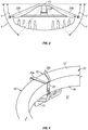
- the hanger 19 from which the lavatory dispensing device 10 depends via the coupling 12, and stalk 22, is mounted upon a portion of a toilet bowl 50, specifically a portion of the rim 57 such that; the top plate 20 is above, and rests upon the top face 54 of the toilet bowl rim 57, a portion of the stalk 22 rests against a portion of the interior side face 56 of the toilet bowl rim 57, each of the grip arms 23A (23B is not visible in this figure) rests against a portion of the exterior side face 55 of the toilet bowl rim 57, or alternately rests against a portion of the exterior side wall 51 of the toilet bowl such that, one or more of the perforations 15 is located beneath the underside 53 of the toilet bowl rim 57 such that, during flushing of the toilet bowl, water and exiting via a part of the toilet bowl rim 57 is directed into or over the cage 11 of the lavatory dispensing device 10.
- a placement is also depicted on Fig. 4 , illustrating the placement and positioning of the lavatory dispensing device 10 within the interior of the toilet bowl 50 such that the aqueous composition formed during flushing by the interaction of the flush water and the lavatory treatment composition 40 contacts the interior side wall 52 of the toilet bowl 50.
- the interior of a toilet bowl 50 can it be treated by the use of a device according to the invention.
- Figure 3 depicts a top plan view of the a lavatory treatment appliance 5 comprising the lavatory dispensing device 10 and improved hanger 19 of Figures 1 and 2 , and more particularly provides for a depiction of the relative arrangements of the hanger 19, its top plate portion 20, and the relative positioning of the left arm section 20A section and a right arm section 20B which extends outwardly from the midpoint 21 and in a forward direction with respect to the downwardly extending stalk 22.
- the relative position of the elements making up the hanger 19 are shown in an "unstressed" configuration, as would be expected prior to mounting of the lavatory dispensing device 10 and the hanger 19 upon a part of a lavatory appliance.
- both of the left arm section 20A section and a right arm section 20B extended forwardly by an angle of "x" degrees relative to a reference plane "W" drawn tangential to the stalk 22 at the midpoint 21 and equidistant from each of the left arm section 20A section and a right arm section 20B.
- the value of "x" is between about 5 - 75 degrees of arc, preferably about 10 - 60 degrees of arc, and particularly preferably are between about 10 - 50 degrees of arc.
- the left arm section 20A section and a right arm section 20B can be moved forwardly such that they can assume an angle of it least about "y" degrees relative to the reference plane W.
- plastic deformation introduces flexural stresses within parts of the hanger 19, such that in a "stressed" configuration, the properties of the material of construction seeks to return to its original "unstressed” configuration (or approximately thereto) its original “unstressed” configuration.
- the hanger 19 optionally but preferably concurrently also having depending therefrom a lavatory dispensing device 10, operates to grip a portion of the lavatory appliance, particularly a toilet bowl upon which it is mounted, particularly as depicted on Figures 3 and 6 .
- the hanger 19 can be easily mounted and easily compressed, such as by simultaneously gripping in each of the tabs 24A, 24B and manually compressing the hanger 19 to assume the stressed configuration wherein concurrently also, the distance between each of the grip arms 23A, 23B is greater than in an unstressed condition, installing the hanger 19 onto the part of the lavatory appliance, e.g., toilet, such as is illustrated in one or more of the accompanying figures, and thereafter releasing the tabs 24A, 24B thereby permitting the hanger 19 to engage a portion of the lavatory appliance, and assume a stressed configuration.
- the lavatory appliance e.g., toilet
- a lavatory dispensing device 10 When a lavatory dispensing device 10 has ceased to function, or has spent its contents, such a lavatory dispensing device 10 depending from the hanger 19 can be easily removed by again simultaneously gripping in each of the tabs 24A, 24B and manually compressing the hanger 19 to assume the stressed configuration thereby permitting the hanger 19 to be removably unmounted or withdrawn from the lavatory appliance.
- Fig. 5 there is illustrated an inventive embodiment wherein in an unstressed configuration the hanger 19, and in particular grip arms 23A, 23B are angled with respect to the stalk 22, and an angle of between about 3 - 45 degrees of arc, preferably an angle between about 5 and 40 degrees of arc, and particularly preferably an angle of between about 10 - 30 degrees of arc, as represented by "z".
- the top plate 20 is not flat and generally plainer as in prior illustrated configurations but is slightly curved.
- the grip arms 23A, 23B and/or the stalk 22 need not be generally linear is illustrated in one or more of the foregoing figures, but can be slightly arcuate or curved along its respective lengths. In such a manner, a respective angle "z" may also be established.
- the cross-sectional or through-section of the top plate is desirably elliptical, but his preferably square, or is even more preferably rectangular initiate.
- Such ensures that upon establishing a "stressed" configuration the dislocation of the grip arms 23A, 23B will be more prone to be in a forwardly direction and thereby increasing the spacing between the stalk 22 and did the grip arms 23A, 23B, rather than in a in a rotational direction.
- any cross-sectional or through-sectional configuration may also be satisfactory.
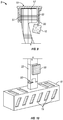
- Figures 7A and 7B present a perspective view of a further embodiment of the a lavatory treatment appliance 5 comprising the improved hanger 19 and a lavatory dispensing device 10 according to the invention, mounted upon a portion of the rim of a toilet bowl.
- the depicted embodiment is a similar in some respects to that disclosed and discussed with reference to prior figures, but differs in that: the a lavatory treatment appliance 5 is mounted in near proximity to, but upon the exterior of the toilet bowl; the hanger 19 is oriented such that the each the grip arms 23A, 23B are placed within the interior of the toilet bowl and when mounted, are urged against a portion of the interior side face 56 of the toilet bowl rim 57 while the stalk 22 rests against and is urged against a portion of the exterior side face 55 of the toilet bowl rim 57; and, wherein the lavatory dispensing device 10 includes further elements here, a fluid conduit portion 50 which extends there from, and extends downwardly into the interior of the toilet bowl.
- a spray dispensing means 53 through which a liquid treatment composition can be dispensed to the interior of the toilet bowl such that it least a portion contacts the interior side wall 52 of the toilet bowl 50.
- the lavatory dispensing device 10 maybe any device which can fulfill such a function for example, may be a device generally in accordance with those devices described in US Serial No. 12/447034 (corresponding to PCT/GB2008003086 ) the contents of which are here in fully incorporated by reference.
- the spray dispensing means maybe any suitable spray dispensing means disclosed in that document, or maybe other spray means known to the art.
- Figures 8A and 8B illustrate in a perspective view a yet further embodiment of a a lavatory treatment appliance 5 comprising an improved hanger 19 and a lavatory dispensing device 10 according to the invention, mounted upon a portion of the rim 57 of a toilet bowl 50.
- the embodiment of Figs. 8A and 8B is similar in most regards to the embodiment of a treated on prior Figs. 7A and 7B , but differs in that: they are provided two fluid conduit portions 50A, 50B which are integral elements of the hanger 19, and the a lavatory treatment appliance 5 additionally includes an air treatment composition dispenser means 70 which may be used to dispense into the ambient environment an air treatment composition.
- Such an air treatment means deliver a quantity of an air treatment composition or an air treatment constituent to the ambient environment within which the lavatory appliance, preferably the toilet bowl, is located.
- Such air treatment composition may be any fragrance or perfume composition, may be any odor treatment, odor masking or odor neutralizing composition, may be an insecticidal composition, or may be any air sterilizing compositions, or may be mixtures of any of the foregoing.
- the air treatment composition dispenser means 70 may be any article or device which suitably operates to dispense an air treatment composition to the ambient environment.
- the air treatment composition dispenser means 70 may be a reservoir which can take any shape or suitable form.
- such a reservoir may include a porous material such as a pad or tablet which is impregnated with, or upon which is absorbed a volatile composition useful in providing an air treatment benefit, or a gel or a solid composition which also contains a volatile air treatment composition which may emanate from reservoir to the ambient environment.
- a porous material such as a pad or tablet which is impregnated with, or upon which is absorbed a volatile composition useful in providing an air treatment benefit, or a gel or a solid composition which also contains a volatile air treatment composition which may emanate from reservoir to the ambient environment.
- the distal end 53 of the fluid conduit portion 50 is located a spray dispensing means 53 through which a liquid treatment composition can be dispensed to the interior of the toilet bowl such that it least a portion contacts the interior side wall 52 of the toilet bowl 50.
- the distal ends of the downwardly extending to grip arms 23A and 23B may also include an angled, rearwardly directed segments, respectively 23AL, 23BL as illustrated, which are configured to resemble the end of a hook, which may be beneficial in improving the placement and retention are the hanger 19.
- the spray dispensing means 53 may be mounted anywhere upon the hanger 19, preferably upon a part of the grip arms 23A and 23B in any part thereof, such as above the angled, rearwardly directed segments 23AL, 23BL or upon these angled, rearwardly directed segments 23AL, 23BL. It is to be further understood that while two spray dispensing means 53 are illustrated in Fig. 8B , the depicted device can include only one such spray dispensing means 53 which by way of example can be mounted on either grip arm 23A or grip arm 23B.
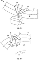
- Figure 9 depicts a side, partial cross-sectional view of a further embodiment of a lavatory treatment appliance 5 comprising a lavatory dispensing device 10 and improved hanger 19 removably mounted upon the rim 57of a toilet bowl.
- a lavatory treatment appliance 5 comprising a lavatory dispensing device 10 and improved hanger 19 removably mounted upon the rim 57of a toilet bowl.
- FIG. 6 which shares many of the features of the embodiment illustrated in Fig. 6 , but further includes: one or more retention pads 80, 81 intermediate portion of the hanger 19 and portions of the toilet rim 57, as well as a joint means 90 intermediates the hanger 19 and the lavatory dispensing device 10.
- retention pads 80, 81 these can be any material, or elements which improves in increasing the interfacial friction between the portions of the hanger 19 upon which such retention pads 80, 81 are positioned and, the portions of the toilet rim 57 which these retention pads 80, 81 contact.
- Such retention pads can be way of nonlimiting example: foamed elastomeric material such as sponges; non-foamed elastomeric material such as naturally occurring or synthetic pads from natural rubber, or from synthetic polymers such as polyisoprene, latex rubber, and the like; adhesive materials such as glues which may be water-soluble glues to facilitate subsequent cleaning, as well as film forming synthetic polymers which may have adhesive properties.
- Such retention pads reduce slippage, particularly inadvertent slippage and displacement of the hanger 19 after it is mounted upon a toilet bowl rim 57.
- the joint means 90 such may be any physical element or device which allows for the separation of the lavatory dispensing device 10 from the hanger 19 without the necessity of removing the hanger 19 from its position mounted upon a toilet bowl rim 57 and/or is a flexible joints which allows for the repositioning of the lavatory dispensing device 10 with respect to the hanger 19, without necessarily displacing the device 10 with respect to the stalk 22.
- a joint means 90 may fulfill both of the aforesaid functions.
- exemplary such joint means including hinges, hook and loop type fasteners, snap-type fittings such as ball and joint type fittings, pins, snap connectors means, friction fitting elements, and the like.
- any means for mechanically connecting the hanger 19 and the lavatory dispensing device 10 may be considered suitable particularly where such means allows adjusting the relative position of the lavatory dispensing device 10 after mounting of the hanger 19.
- Figure 10 depicts a detailed perspective view of a part of the lavatory treatment device and hanger of Fig. 9 illustrating a preferred embodiment of the joint means 90, here depicted as a knuckle hinge element 92 forming part of the stalk 22. While not clearly depicted is to be understood that the particular knuckle hinge element 92 depicted may be mechanically snapped apart so to provide for easy separation of the hanger 19 from the lavatory dispensing device 10, and yet, when in its assembled configuration within the element 92 are sufficient frictional forces such that the configuration of the hanger 19 with the lavatory dispensing device 10 can be angled, and retained in such an angle as depicted on Figure 9 . In such a manner, the use of a joint means 90 allows for optimization of the placement of the lavatory dispensing device 10 within a toilet bowl.
- a separable joint means 90 permits for the provision of "refillable" embodiment of the lavatory treatment device, whereby a mounted hanger 19 can be retained upon a toilet bowl rim, and replacement lavatory dispensing devices 10 can be provided as needed without requiring on mounting war displacement of the mounted hanger 19.
- Both of the hanger 19 and the lavatory dispensing device 10 according to the invention can be made of any suitable sufficiently flexible or deformable material, but advantageously at least the hanger 19 is formed of a flexible material.
- a synthetic polymers including thermosettable or thermoformable synthetic polymers such as are widely used in casting or injection molding may be used.
- Exemplary synthetic polymers such as polyamides, polyolefins (e.g., polypropylene, polyethylene) as well as polyalkyleneterephalates (i.e., polyethylene terephthalate, polybutylene terephthalate), polystyrenes, polysulfones, polycarbonates as well as copolymers formed from monomers of one or more of the foregoing.
- thermoformable or thermosetting synthetic polymers come into consideration as suitable materials of construction as such are typically easily formed into a desired configuration for an article, may have good flexural and deformation characteristics to assume both stressed and unstressed configurations for the hanger 19 as required, and are resistant to many chemicals. Of course other materials may be used as well where such are found to be suitable.
Landscapes
- Health & Medical Sciences (AREA)
- Public Health (AREA)
- Epidemiology (AREA)
- Life Sciences & Earth Sciences (AREA)
- Engineering & Computer Science (AREA)
- Hydrology & Water Resources (AREA)
- Water Supply & Treatment (AREA)
- Bidet-Like Cleaning Device And Other Flush Toilet Accessories (AREA)
- Toilet Supplies (AREA)
Description
- The present invention relates to a hanger for a lavatory treatment device. More particularly the present invention relates to a hanger for a lavatory treatment device which is used to position said device in the immediate proximity of a toilet bowl.
- The prior art has suggested various hangers which are useful with devices for providing a technical effect, e.g., delivering a treatment composition, providing a cleaning composition, providing an air treatment benefit to a lavatory appliance, e.g., a urinal, bidet or toilet. Examples of such hangers and devices comprising hangers include the following:
US 1880912 ,US 2011732 ,US 2985377 ,US 3088126 ,US 3290699 ,US 3604021 ,US 3947901 ,US 4143431 ,US 4247070 ,US 4301556 ,US 4455692 ,US 5206959 , andUS 6817040 .US4261957 discloses a hanger having all features of the preamble of claim 1. While each are in some respect satisfactory, there nonetheless remains a real and urgent need in the art for further improved hangers for a lavatory treatment device, as well as lavatory treatment devices comprising such an improved hanger. - It is to these and as well as further objects that are addressed by the present invention.
- According to first aspect, there is provided an improved
hanger 19 for alavatory treatment device 10 according to claim 1. - According to a second aspect, there is provided a lavatory treatment appliance according to claim 8.
- In a third aspect, the present invention provides for a method for removably mounting and positioning a lavatory treatment device in the immediate proximity of a part of a lavatory appliance, and especially a toilet bowl, according to claim 9.
- These and further aspects of the invention will be better understood from a reading of the following disclosure and the accompanying drawings. In the accompanying drawings like numerals are employed to designate like parts throughout the same.
-
Figure 1 depicts in a perspective view the front of a preferred embodiment of a lavatory treatment appliance including an improved hanger. -
Figure 2 depicts a rear perspective view of the lavatory treatment appliance and improved hanger ofFigure 1 . -
Fig. 3 depicts a top plan view of the lavatory treatment appliance and improved hanger ofFigures 1 and 2 . -
Figure 4 depicts a view of the lavatory treatment applicance and improved hanger ofFigures 1 and 2 removably mounted upon the rim of a toilet bowl. -
Figure 5 depicts a side, partial cross-sectional view of the lavatory treatment appliance and improved hanger ofFigures 1 and 2 . -
Figure 6 depicts a side, partial cross-sectional view of the lavatory treatment appliance and improved hanger ofFigure 3 removably mounted upon the rim of a toilet bowl. -
Figures 7A and 7B respectively illustrate a perspective view of a further embodiment of the improved hanger and a lavatory treatment appliance according to the invention, mounted upon a portion of the rim of a toilet bowl. -
Figures 8A and 8B respectively illustrate a perspective view of a further embodiment of the improved hanger and a lavatory treatment appliance according to the invention, mounted upon a portion of the rim of a toilet bowl. -
Figure 9 depicts a side, partial cross-sectional view of a further embodiment of a lavatory treatment appliance and improved hanger removably mounted upon the rim of a toilet bowl. -
Figure 10 depicts a detailed perspective view of a part of the lavatory treatment appliance and hanger ofFig. 9 . - With reference now to
Figs. 1 and 2 , there is depicted alavatory treatment appliance 5 which comprises alavatory dispensing device 10 which is affixed to, and which depends from, ahanger 19 via anintermediate coupling 12. Thehanger 19 includes atop plate portion 20 which from anapproximate midpoint 21, depends a downwardly extendingstalk 22 which extends downwardly towards theintermediate coupling 12. In the depicted embodiment, thestalk 22 includes an upper stalk section 22A, a lower stalk section 22B, and here, an angled midsection 22C ,which operates to divert the direction of the downwardly extendingstalk 22 such that the approximately vertical stalk section 22A is diverted forwardly at its lower stalk section 22B due to the introduced angle imposed by the angled midsection 22C. In certain preferred embodiments, the configuration of thestalk 22 in the manner disclosed is advantageous in that it provides for improved placement of thelavatory dispensing device 10 with relation to part of a lavatory appliance, however, such is not required and it is foreseen that thestalk 22 may be essentially linear in its configuration, or may have an angled midsection 22C which diverts the direction of the downwardly extendingstalk 22 rearwardly, or may include one or more angled midsections which introduce various plural degrees of diversion to thestalk 22. Indeed it is also foreseen that thestalk 22 may be flexible so that it may include elements or be formed of a material which allows it to be bent from a first configuration, e.g., an essentially linear configuration, to assume a further configuration which is retained, and which may optionally be still further reconfigured, such as by manually bending thestalk 22 or other portions of thelavatory treatment appliance 5. Thetop plate portion 20 includes a left arm section 20A section and a right arm section 20B which extends outwardly from themidpoint 21 and in a forward direction with respect to thestalk 22. The left arm section 20A and the right arm section 20B are most desirably essentially symmetrical about themidpoint 21 and further are angled forwardly. At the ends of each of the left arm section 20A section and a right arm section 20B is a downwardly extending to grip arm, respectively 23A and 23B. with respect to one other, each of the grip arms 23A, 23B are preferably parallel and spaced part from one another, and also each is located forward of thestalk 22. In certain preferred embodiments, the orientation ofstalk 22, preferably at least the upper stalk section 22A thereof, and each of the grip arms 23A, 23B are parallel with respect to one another, while in other preferred embodiments, the orientation of each of the grip arms 23A, 23B are parallel with respect to each other, but are angled with respect to thestalk 22, preferably at least the upper stalk section 22A thereof. Optionally but preferably, thehanger 19 includes, extending outwardly from the ends of each other the left arm section 20A section and a right arm section 20B and/or each of the grip arms 23A, 23B gripping tabs, respectively 24A and 24B which provide means for manual gripping of thehanger 19 by a user either installing, or removing thelavatory treatment appliance 5 and/or thehanger 10 from a lavatory appliance. With respect to thelavatory treatment device 10, in the embodiment illustrated in these figures there is depicted acage 11 which is essentially a housing adapted to contain a quantity of a solid, liquid, or semi-solid, or gelled lavatory treatment composition, typically containing one or more of: surfactants, bleach, fragrance, disinfectant, anti-limescale treatment agent and the like which is removably mounted upon the rim of a toilet bowl such that water flushing from the underside of the rim of the toilet bowl enters into the interior of thecage 11 via one or more of theperforations 15, comes into contact with the lavatory treatment composition and thereafter exits thecage 11 from whence it flows and treats the interior surfaces of the toilet bowl. Such is suitably illustrated onFigure 5 which depicts a side, partial cross-sectional view of the lavatory treatment device and improved hanger ofFigures 1 and 2 , wherein alavatory treatment composition 40, here in the form of a cake or block is present within the interior of thecage 11. Thecage 11 is movably affixed to thehanger 19 via acoupling 12, which is here intended to illustrate a friction type, or rack-and-pawl type of mechanical interconnection between thehanger 19 and thecage 11. Use of such acoupling 12 permits for slidable engagement between a least a portion of thestalk 22, here specifically part of the lower stalk section 22B such that the position of thecage 11 relative to thestalk 22 and thus, by default also relative to the position (and distance) of thetop plate 20 of thehanger 19. Such also dictates the relative positioning in placement of thelavatory dispensing device 10 with respect to the rim of a toilet bowl, as is better illustrated onFig. 6 . As is visible from that figure, thehanger 19 from which thelavatory dispensing device 10 depends via thecoupling 12, andstalk 22, is mounted upon a portion of atoilet bowl 50, specifically a portion of therim 57 such that; thetop plate 20 is above, and rests upon thetop face 54 of thetoilet bowl rim 57, a portion of thestalk 22 rests against a portion of theinterior side face 56 of thetoilet bowl rim 57, each of the grip arms 23A (23B is not visible in this figure) rests against a portion of theexterior side face 55 of thetoilet bowl rim 57, or alternately rests against a portion of theexterior side wall 51 of the toilet bowl such that, one or more of theperforations 15 is located beneath theunderside 53 of thetoilet bowl rim 57 such that, during flushing of the toilet bowl, water and exiting via a part of thetoilet bowl rim 57 is directed into or over thecage 11 of thelavatory dispensing device 10. Such a placement is also depicted onFig. 4 , illustrating the placement and positioning of thelavatory dispensing device 10 within the interior of thetoilet bowl 50 such that the aqueous composition formed during flushing by the interaction of the flush water and thelavatory treatment composition 40 contacts theinterior side wall 52 of thetoilet bowl 50. In such manner, the interior of atoilet bowl 50 can it be treated by the use of a device according to the invention. -
Figure 3 depicts a top plan view of the alavatory treatment appliance 5 comprising thelavatory dispensing device 10 and improvedhanger 19 ofFigures 1 and 2 , and more particularly provides for a depiction of the relative arrangements of thehanger 19, itstop plate portion 20, and the relative positioning of the left arm section 20A section and a right arm section 20B which extends outwardly from themidpoint 21 and in a forward direction with respect to the downwardly extendingstalk 22. In this figure, the relative position of the elements making up thehanger 19 are shown in an "unstressed" configuration, as would be expected prior to mounting of thelavatory dispensing device 10 and thehanger 19 upon a part of a lavatory appliance. In such a condition, both of the left arm section 20A section and a right arm section 20B extended forwardly by an angle of "x" degrees relative to a reference plane "W" drawn tangential to thestalk 22 at themidpoint 21 and equidistant from each of the left arm section 20A section and a right arm section 20B. In preferred embodiments, the value of "x" is between about 5 - 75 degrees of arc, preferably about 10 - 60 degrees of arc, and particularly preferably are between about 10 - 50 degrees of arc. According to the invention, it is required that each of the left arm section 20A section and a right arm section 20B be forwardly movable, that is to say, to form an even greater angle with respect to the reference plane W. Such which is achieved by the material of construction of the hanger 1 being sufficiently flexible or deformable to permit for plastic deformation of thehanger 19 in such a manner as shown in the figures. Advantageously then, the left arm section 20A section and a right arm section 20B can be moved forwardly such that they can assume an angle of it least about "y" degrees relative to the reference plane W. Optionally, but particularly advantageously, such plastic deformation introduces flexural stresses within parts of thehanger 19, such that in a "stressed" configuration, the properties of the material of construction seeks to return to its original "unstressed" configuration (or approximately thereto) its original "unstressed" configuration. In this manner, thehanger 19, optionally but preferably concurrently also having depending therefrom alavatory dispensing device 10, operates to grip a portion of the lavatory appliance, particularly a toilet bowl upon which it is mounted, particularly as depicted onFigures 3 and6 . These internal stresses in the stressed configuration such that; thetop plate 20 is above and rests upon thetop face 54 of thetoilet bowl rim 57; a portion of thestalk 22 rests against and is urged against a portion of theinterior side face 56 of thetoilet bowl rim 57; and concurrently each of the grip arms 23A, 23B rests against and are urged against a portion of theexterior side face 55 of thetoilet bowl rim 57, or alternately rests against and are urged against a portion of theexterior side wall 51 of the toilet bowl. Thus, the effect of flexural stresses within thehanger 19 resulting in compressive effects urging each the grip arms 23A, 23B to move towards thestalk 22 provides for improved retention of thehanger 19 in the position in which it has been removably mounted. Thehanger 19 can be easily mounted and easily compressed, such as by simultaneously gripping in each of the tabs 24A, 24B and manually compressing thehanger 19 to assume the stressed configuration wherein concurrently also, the distance between each of the grip arms 23A, 23B is greater than in an unstressed condition, installing thehanger 19 onto the part of the lavatory appliance, e.g., toilet, such as is illustrated in one or more of the accompanying figures, and thereafter releasing the tabs 24A, 24B thereby permitting thehanger 19 to engage a portion of the lavatory appliance, and assume a stressed configuration. When alavatory dispensing device 10 has ceased to function, or has spent its contents, such alavatory dispensing device 10 depending from thehanger 19 can be easily removed by again simultaneously gripping in each of the tabs 24A, 24B and manually compressing thehanger 19 to assume the stressed configuration thereby permitting thehanger 19 to be removably unmounted or withdrawn from the lavatory appliance. - Briefly returning to
Fig. 5 , there is illustrated an inventive embodiment wherein in an unstressed configuration thehanger 19, and in particular grip arms 23A, 23B are angled with respect to thestalk 22, and an angle of between about 3 - 45 degrees of arc, preferably an angle between about 5 and 40 degrees of arc, and particularly preferably an angle of between about 10 - 30 degrees of arc, as represented by "z". Such may occur wherein thetop plate 20 is not flat and generally plainer as in prior illustrated configurations but is slightly curved. Alternately, the grip arms 23A, 23B and/or thestalk 22 need not be generally linear is illustrated in one or more of the foregoing figures, but can be slightly arcuate or curved along its respective lengths. In such a manner, a respective angle "z" may also be established. - Advantageously, in accordance with preferred embodiments, the cross-sectional or through-section of the top plate is desirably elliptical, but his preferably square, or is even more preferably rectangular initiate. Such ensures that upon establishing a "stressed" configuration the dislocation of the grip arms 23A, 23B will be more prone to be in a forwardly direction and thereby increasing the spacing between the
stalk 22 and did the grip arms 23A, 23B, rather than in a in a rotational direction. However, while such are preferred, these are not necessarily limiting of the invention as any cross-sectional or through-sectional configuration may also be satisfactory. -
Figures 7A and 7B present a perspective view of a further embodiment of the alavatory treatment appliance 5 comprising the improvedhanger 19 and alavatory dispensing device 10 according to the invention, mounted upon a portion of the rim of a toilet bowl. The depicted embodiment is a similar in some respects to that disclosed and discussed with reference to prior figures, but differs in that: the alavatory treatment appliance 5 is mounted in near proximity to, but upon the exterior of the toilet bowl; thehanger 19 is oriented such that the each the grip arms 23A, 23B are placed within the interior of the toilet bowl and when mounted, are urged against a portion of theinterior side face 56 of thetoilet bowl rim 57 while thestalk 22 rests against and is urged against a portion of theexterior side face 55 of thetoilet bowl rim 57; and, wherein thelavatory dispensing device 10 includes further elements here, afluid conduit portion 50 which extends there from, and extends downwardly into the interior of the toilet bowl. At thedistal end 53 of thefluid conduit portion 50 is located a spray dispensing means 53 through which a liquid treatment composition can be dispensed to the interior of the toilet bowl such that it least a portion contacts theinterior side wall 52 of thetoilet bowl 50. Thelavatory dispensing device 10 maybe any device which can fulfill such a function for example, may be a device generally in accordance with those devices described inUS Serial No. 12/447034 PCT/GB2008003086 -
Figures 8A and 8B illustrate in a perspective view a yet further embodiment of a alavatory treatment appliance 5 comprising an improvedhanger 19 and alavatory dispensing device 10 according to the invention, mounted upon a portion of therim 57 of atoilet bowl 50. The embodiment ofFigs. 8A and 8B is similar in most regards to the embodiment of a treated on priorFigs. 7A and 7B , but differs in that: they are provided two fluid conduit portions 50A, 50B which are integral elements of thehanger 19, and the alavatory treatment appliance 5 additionally includes an air treatment composition dispenser means 70 which may be used to dispense into the ambient environment an air treatment composition. Such an air treatment means deliver a quantity of an air treatment composition or an air treatment constituent to the ambient environment within which the lavatory appliance, preferably the toilet bowl, is located. Such air treatment composition may be any fragrance or perfume composition, may be any odor treatment, odor masking or odor neutralizing composition, may be an insecticidal composition, or may be any air sterilizing compositions, or may be mixtures of any of the foregoing. The air treatment composition dispenser means 70 may be any article or device which suitably operates to dispense an air treatment composition to the ambient environment. By way of nonlimiting example, the air treatment composition dispenser means 70 may be a reservoir which can take any shape or suitable form. By way of nonlimiting examples, such a reservoir may include a porous material such as a pad or tablet which is impregnated with, or upon which is absorbed a volatile composition useful in providing an air treatment benefit, or a gel or a solid composition which also contains a volatile air treatment composition which may emanate from reservoir to the ambient environment. - With respect to the two fluid conduit portions 50A, 50B which are integral parts of the grip arms respectively 23A and 23B of the
hanger 19, as is visible from this figure, thedistal end 53 of thefluid conduit portion 50 is located a spray dispensing means 53 through which a liquid treatment composition can be dispensed to the interior of the toilet bowl such that it least a portion contacts theinterior side wall 52 of thetoilet bowl 50. The distal ends of the downwardly extending to grip arms 23A and 23B may also include an angled, rearwardly directed segments, respectively 23AL, 23BL as illustrated, which are configured to resemble the end of a hook, which may be beneficial in improving the placement and retention are thehanger 19. The spray dispensing means 53 may be mounted anywhere upon thehanger 19, preferably upon a part of the grip arms 23A and 23B in any part thereof, such as above the angled, rearwardly directed segments 23AL, 23BL or upon these angled, rearwardly directed segments 23AL, 23BL. It is to be further understood that while two spray dispensing means 53 are illustrated inFig. 8B , the depicted device can include only one such spray dispensing means 53 which by way of example can be mounted on either grip arm 23A or grip arm 23B. -
Figure 9 depicts a side, partial cross-sectional view of a further embodiment of alavatory treatment appliance 5 comprising alavatory dispensing device 10 andimproved hanger 19 removably mounted upon the rim 57of a toilet bowl. In the illustrated embodiment, which shares many of the features of the embodiment illustrated inFig. 6 , but further includes: one ormore retention pads hanger 19 and portions of thetoilet rim 57, as well as a joint means 90 intermediates thehanger 19 and thelavatory dispensing device 10. With regard to theretention pads hanger 19 upon whichsuch retention pads toilet rim 57 which theseretention pads hanger 19 after it is mounted upon atoilet bowl rim 57. With regard to the joint means 90, such may be any physical element or device which allows for the separation of thelavatory dispensing device 10 from thehanger 19 without the necessity of removing thehanger 19 from its position mounted upon atoilet bowl rim 57 and/or is a flexible joints which allows for the repositioning of thelavatory dispensing device 10 with respect to thehanger 19, without necessarily displacing thedevice 10 with respect to thestalk 22. Advantageously such a joint means 90 may fulfill both of the aforesaid functions. The way of nonlimiting example, exemplary such joint means including hinges, hook and loop type fasteners, snap-type fittings such as ball and joint type fittings, pins, snap connectors means, friction fitting elements, and the like. Virtually, any means for mechanically connecting thehanger 19 and thelavatory dispensing device 10 may be considered suitable particularly where such means allows adjusting the relative position of thelavatory dispensing device 10 after mounting of thehanger 19. -
Figure 10 depicts a detailed perspective view of a part of the lavatory treatment device and hanger ofFig. 9 illustrating a preferred embodiment of the joint means 90, here depicted as aknuckle hinge element 92 forming part of thestalk 22. While not clearly depicted is to be understood that the particularknuckle hinge element 92 depicted may be mechanically snapped apart so to provide for easy separation of thehanger 19 from thelavatory dispensing device 10, and yet, when in its assembled configuration within theelement 92 are sufficient frictional forces such that the configuration of thehanger 19 with thelavatory dispensing device 10 can be angled, and retained in such an angle as depicted onFigure 9 . In such a manner, the use of a joint means 90 allows for optimization of the placement of thelavatory dispensing device 10 within a toilet bowl. - Further, the provision of a separable joint means 90 permits for the provision of "refillable" embodiment of the lavatory treatment device, whereby a mounted
hanger 19 can be retained upon a toilet bowl rim, and replacementlavatory dispensing devices 10 can be provided as needed without requiring on mounting war displacement of the mountedhanger 19. - Both of the
hanger 19 and thelavatory dispensing device 10 according to the invention can be made of any suitable sufficiently flexible or deformable material, but advantageously at least thehanger 19 is formed of a flexible material. Advantageously the use of a synthetic polymers including thermosettable or thermoformable synthetic polymers such as are widely used in casting or injection molding may be used. Exemplary synthetic polymers such as polyamides, polyolefins (e.g., polypropylene, polyethylene) as well as polyalkyleneterephalates (i.e., polyethylene terephthalate, polybutylene terephthalate), polystyrenes, polysulfones, polycarbonates as well as copolymers formed from monomers of one or more of the foregoing. One or more of such thermoformable or thermosetting synthetic polymers come into consideration as suitable materials of construction as such are typically easily formed into a desired configuration for an article, may have good flexural and deformation characteristics to assume both stressed and unstressed configurations for thehanger 19 as required, and are resistant to many chemicals. Of course other materials may be used as well where such are found to be suitable.
Claims (9)
- An improved hanger (19) for a lavatory treatment device (10) which comprises:a top plate portion (20) which from an approximate midpoint (21), depends a downwardly extending stalk (22), wherein the top plate portion (20) includes a left arm section (20A) section and a right arm section (20B) which extends outwardly from the midpoint (21) and in a forward direction with respect to the stalk (22), wherein the left arm section (20A) and the right arm section (20B), are preferably essentially symmetrical about the midpoint (21) and at the ends of each of the left arm section (20A) section and a right arm section (20B) are each a downwardly extending to grip arm, (23A), (23B), which grip arms (23A), (23B) are parallel and spaced part from one another, and also each is located forward of the stalk(22), characterised in that the left arm section (20A) and the right arm section (20B) are angled forwardly with respect to the stalk (22), whereby a both of the left arm section(20A) and the right arm section(20B) are extended forwardly by an unstressed angle relative to a reference plane "W" drawn tangential to the stalk(22) at the midpoint(21)and equidistant from each of the left arm section(20A) and the right arm section(20B) each of the left arm section and the right arm section being forwardly movable to form a greater angle with respect to the reference plane "W", which is achieved by the material of construction of the hanger (19) being sufficiently flexible or deformable to permit for plastic deformation of the hanger (19).
- An improved hanger (19) for a lavatory treatment device 10 according to claim 1, wherein, the orientation of stalk (22), and each of the grip arms (23A), (23B) are parallel with respect to one another.
- An improved hanger (19) for a lavatory device (10) according to claim 1, wherein the orientation of each of the grip arms (23A), (23B) are parallel with respect to each other, but are angled with respect to the stalk (22).
- An improved hanger (19) for a lavatory device (10) according to any of claims 1 - 3 wherein the stalk (22) includes an upper stalk section (22A), a lower stalk section (22B), and here, an angled midsection (22C), which operates to divert the direction of the downwardly extending stalk (22) such that the approximately vertical stalk section (22A) is diverted forwardly at its lower stalk section (22B) due to the introduced angle imposed by the angled midsection (22C).
- An improved hanger (19) for a lavatory device (10) according any of claims 1 -4, wherein both of the left arm section 20A section and a right arm section 20B extended forwardly by an angle of "x" degrees relative to a reference plane "W" drawn tangential to the stalk (22) at the midpoint (21) and equidistant from each of the left arm section (20A) section and a right arm section (20B).
- An improved hanger (19) for a lavatory device (10) according to claim 5, wherein the value of "x" is between about 5 - 75 degrees.
- An improved hanger (19) for a lavatory device (10) according any of claims 1 -6, wherein grip arms (23A), (23B) are angled with respect to the stalk (22), and an angle of between about 3 - 45 degrees of arc, preferably an angle between about 5 and 40 degrees of arc, and particularly preferably an angle of between about 10 - 30 degrees of arc
- A lavatory treatment appliance (5) which comprises a lavatory dispensing device (10) and an improved hanger (19) according to any of claims 1 - 2.
- A method for removably mounting and positioning a lavatory treatment device (10) in the immediate proximity of a part of a lavatory appliance, especially a toilet bowl, which method comprises the steps of: providing an improved hanger (19) according to any of claims 1 - 8 for a lavatory treatment device (10) or a lavatory treatment appliance (5) according to claim 8, and, removably mounting affixing a part of the improved hanger (19) to a part of a lavatory appliance, and thereby positioning the lavatory treatment appliance (5) or a depending lavatory treatment device (10) in the immediate proximity of the lavatory appliance.
Applications Claiming Priority (2)
| Application Number | Priority Date | Filing Date | Title |
|---|---|---|---|
| GB0918759A GB0918759D0 (en) | 2009-10-27 | 2009-10-27 | Hanger for a lavatory treatment device |
| PCT/GB2010/051629 WO2011051695A1 (en) | 2009-10-27 | 2010-09-30 | Hanger for a lavatory treatment device |
Publications (2)
| Publication Number | Publication Date |
|---|---|
| EP2494116A1 EP2494116A1 (en) | 2012-09-05 |
| EP2494116B1 true EP2494116B1 (en) | 2017-04-12 |
Family
ID=41426726
Family Applications (1)
| Application Number | Title | Priority Date | Filing Date |
|---|---|---|---|
| EP10763845.4A Not-in-force EP2494116B1 (en) | 2009-10-27 | 2010-09-30 | Hanger for a lavatory treatment device |
Country Status (9)
| Country | Link |
|---|---|
| US (1) | US9003572B2 (en) |
| EP (1) | EP2494116B1 (en) |
| AU (1) | AU2010311189B2 (en) |
| BR (1) | BR112012009819A2 (en) |
| CA (1) | CA2779802C (en) |
| GB (1) | GB0918759D0 (en) |
| RU (1) | RU2541397C2 (en) |
| WO (1) | WO2011051695A1 (en) |
| ZA (1) | ZA201203159B (en) |
Families Citing this family (13)
| Publication number | Priority date | Publication date | Assignee | Title |
|---|---|---|---|---|
| GB0718420D0 (en) * | 2007-09-21 | 2007-10-31 | Reckitt Benckiser Inc | Improvements in dispensing devices |
| US20120110722A1 (en) * | 2010-11-09 | 2012-05-10 | Matthew Abbondanzio | Clip for Mounting a Fluid Delivery Device |
| JP6315932B2 (en) * | 2013-09-26 | 2018-04-25 | 小林製薬株式会社 | Drug supply tool |
| DE102016100293A1 (en) * | 2016-01-11 | 2017-07-13 | Budich International Gmbh | WC-agent holder |
| ITUB20160666A1 (en) * | 2016-02-11 | 2017-08-11 | Deco Ind S Coop P A | SUPPORT DEVICE FOR HYGIENIC EQUIPMENT AND HYGIENIC EQUIPMENT USING THE SAME |
| US10044710B2 (en) | 2016-02-22 | 2018-08-07 | Bpip Limited Liability Company | Device and method for validating a user using an intelligent voice print |
| US10669705B2 (en) | 2016-07-05 | 2020-06-02 | Willert Home Products, Inc. | Toilet bowl treatment apparatus and method of making same |
| CA3120904C (en) * | 2019-04-25 | 2023-09-19 | Guangzhou Blue Moon Industrial Co., Ltd. | Extended-time release method and device for toilet cleaner |
| DE102019130710A1 (en) * | 2019-11-14 | 2021-05-20 | Henkel Ag & Co. Kgaa | Toilet basket |
| WO2021212091A1 (en) * | 2020-04-17 | 2021-10-21 | Smith Andrea Nicole | Adapter device |
| US11214949B2 (en) * | 2020-04-19 | 2022-01-04 | Gilbert Gonzales | Toilet deodorant container |
| USD969962S1 (en) * | 2020-11-18 | 2022-11-15 | Henkel Ag & Co. Kgaa | Toilet rim blocks |
| USD968556S1 (en) * | 2020-11-18 | 2022-11-01 | Henkel Ag & Co. Kgaa | Toilet rim blocks |
Citations (1)
| Publication number | Priority date | Publication date | Assignee | Title |
|---|---|---|---|---|
| US4096593A (en) * | 1976-07-15 | 1978-06-27 | Eftichios Van Vlahakis | Toilet bowl dispenser |
Family Cites Families (19)
| Publication number | Priority date | Publication date | Assignee | Title |
|---|---|---|---|---|
| US1880912A (en) | 1931-05-29 | 1932-10-04 | Mary E Forchheimer | Deodorant container for toilet bowls |
| US2011732A (en) | 1934-10-04 | 1935-08-20 | Puro Company Inc | Deodorizer |
| US2985377A (en) | 1958-01-29 | 1961-05-23 | Puro Co Inc | Toilet bowl deodorizers |
| US3088126A (en) | 1961-03-10 | 1963-05-07 | Frank J Curran Co | Bowl deodorant hanger |
| US3290699A (en) | 1964-04-15 | 1966-12-13 | Schneid Inc I | Toilet bowl deodorizer |
| US3604021A (en) | 1969-05-15 | 1971-09-14 | Elton Ind Corp | Urinal tablet |
| US3947901A (en) | 1972-08-25 | 1976-04-06 | Irwin-Willert Company | Hanger for toilet bowl deodorant |
| DK307676A (en) | 1975-07-09 | 1977-01-10 | Oreal | BRAKE WITH BREAKTHROUGH BASKET SPECIALLY FOR INCLUDING A BLOCK OF A WATER-SOLUBLE PRODUCT FOR DISINFECTION AND DESODORIZATION OF TOILET BASINS |
| DE7834350U1 (en) * | 1978-11-18 | 1979-03-22 | Globol-Werk Gmbh, 8858 Neuburg | BRACKET FOR TOILET DEODORANT |
| DE2917083B1 (en) | 1979-04-27 | 1980-07-10 | Globol Werke Gmbh | Bracket for toilet deodorants |
| US4247070A (en) | 1979-07-23 | 1981-01-27 | The Procter & Gamble Company | Tilt compensating hanger for toilet tank dispensing apparatus |
| FR2532347B1 (en) * | 1982-08-26 | 1987-02-20 | Oreal | DEVICE FOR THE DISPENSING OF WATER-SOLUBLE PRODUCTS IN A WATER FLUSH |
| US4455692A (en) | 1983-05-09 | 1984-06-26 | The Drackett Company | Chemical dispenser safety hanger |
| US5206959A (en) | 1991-09-03 | 1993-05-04 | Joseph Provenzano | Toilet deodorizer |
| US5375799A (en) * | 1992-09-25 | 1994-12-27 | Hollister Incorporated | Collection bag hanger with rail width-adjustable hook arms |
| US6055679A (en) * | 1995-03-03 | 2000-05-02 | S. C. Johnson & Son, Inc. | Passive lavatory cleanser dispensing system |
| CA2483939C (en) | 2002-05-10 | 2007-10-09 | S. C. Johnson & Son, Inc. | Toilet rim mounted liquid dispenser using vertical wicking system |
| WO2007107769A1 (en) | 2006-03-22 | 2007-09-27 | Reckitt Benckiser Inc. | Improvements in lavatory dispensing devices |
| GB0717951D0 (en) | 2007-09-14 | 2007-10-24 | Reckitt Benckiser Inc | Improvements in lavatory treatment devices |
-
2009
- 2009-10-27 GB GB0918759A patent/GB0918759D0/en not_active Ceased
-
2010
- 2010-09-30 RU RU2012121817/13A patent/RU2541397C2/en not_active IP Right Cessation
- 2010-09-30 AU AU2010311189A patent/AU2010311189B2/en not_active Ceased
- 2010-09-30 BR BR112012009819A patent/BR112012009819A2/en not_active Application Discontinuation
- 2010-09-30 US US13/503,914 patent/US9003572B2/en not_active Expired - Fee Related
- 2010-09-30 EP EP10763845.4A patent/EP2494116B1/en not_active Not-in-force
- 2010-09-30 CA CA2779802A patent/CA2779802C/en not_active Expired - Fee Related
- 2010-09-30 WO PCT/GB2010/051629 patent/WO2011051695A1/en not_active Ceased
-
2012
- 2012-05-02 ZA ZA2012/03159A patent/ZA201203159B/en unknown
Patent Citations (1)
| Publication number | Priority date | Publication date | Assignee | Title |
|---|---|---|---|---|
| US4096593A (en) * | 1976-07-15 | 1978-06-27 | Eftichios Van Vlahakis | Toilet bowl dispenser |
Also Published As
| Publication number | Publication date |
|---|---|
| GB0918759D0 (en) | 2009-12-09 |
| AU2010311189A1 (en) | 2012-05-31 |
| CA2779802C (en) | 2017-04-04 |
| ZA201203159B (en) | 2013-07-31 |
| AU2010311189B2 (en) | 2014-11-06 |
| BR112012009819A2 (en) | 2016-11-22 |
| US9003572B2 (en) | 2015-04-14 |
| US20130112830A1 (en) | 2013-05-09 |
| RU2012121817A (en) | 2013-12-10 |
| EP2494116A1 (en) | 2012-09-05 |
| CA2779802A1 (en) | 2011-05-05 |
| WO2011051695A1 (en) | 2011-05-05 |
| RU2541397C2 (en) | 2015-02-10 |
Similar Documents
| Publication | Publication Date | Title |
|---|---|---|
| AU2010311189B2 (en) | Hanger for a lavatory treatment device | |
| EP2141221B1 (en) | Adhesive toilet product, containment and applicator device thereto | |
| USD596033S1 (en) | Applicator | |
| USD578331S1 (en) | Liquid soap dispenser | |
| CN103717811B (en) | Gel WC cleaning article is applied directly to WC and just uses applicator on the surface of device | |
| GB2502763A (en) | Applicator for applying a dose of a treatment composition | |
| DE60028814D1 (en) | Liquid dispenser for cleaning toilet bowls | |
| ATE315140T1 (en) | DISPENSING DEVICE FOR DISPENSING ACTIVE FLUIDS INTO THE FISHING LIQUID IN A TOILET BASIN | |
| CA2528947A1 (en) | Improved dispensing device | |
| ATE344355T1 (en) | DISPENSER FOR SURFACE TENSION-REDUCING FRAGRANCE AND CLEANING LIQUIDS, ESPECIALLY FOR TOILET BOWLS | |
| USD537722S1 (en) | Applicator refill | |
| USD538164S1 (en) | Applicator | |
| JP2006525055A (en) | Toilet bowl cleaning device | |
| EP3533943A1 (en) | Anti-splash device for toilets | |
| EP2407601A3 (en) | Perfuming hygiene device for sanitary fixtures | |
| WO2004096969A3 (en) | A lavatory bowl rim-block | |
| CN2934406Y (en) | Wall-hanging type anti-splash buffer device in seat type toilet | |
| JP3845791B2 (en) | Applicator | |
| EP0506464A2 (en) | An anti-liquid splash device | |
| WO2014074599A1 (en) | Single-dose applicator and method | |
| JP3096517U (en) | Spray catch panel for urinals for men | |
| DE102011055412A1 (en) | Device for fixing cleaning agents to sanitary articles | |
| CN201365875Y (en) | Little boy urination training target | |
| JP2009091892A (en) | Chemical retainer for urinal | |
| ITMI20011669A0 (en) | DEVICE FOR THE AUTOMATIC DISPENSING OF CLEANING AND DEODORIZING PRODUCTS FOR TOILET BOWLS |
Legal Events
| Date | Code | Title | Description |
|---|---|---|---|
| PUAI | Public reference made under article 153(3) epc to a published international application that has entered the european phase |
Free format text: ORIGINAL CODE: 0009012 |
|
| 17P | Request for examination filed |
Effective date: 20120501 |
|
| AK | Designated contracting states |
Kind code of ref document: A1 Designated state(s): AL AT BE BG CH CY CZ DE DK EE ES FI FR GB GR HR HU IE IS IT LI LT LU LV MC MK MT NL NO PL PT RO SE SI SK SM TR |
|
| DAX | Request for extension of the european patent (deleted) | ||
| 17Q | First examination report despatched |
Effective date: 20160120 |
|
| GRAP | Despatch of communication of intention to grant a patent |
Free format text: ORIGINAL CODE: EPIDOSNIGR1 |
|
| INTG | Intention to grant announced |
Effective date: 20161201 |
|
| GRAS | Grant fee paid |
Free format text: ORIGINAL CODE: EPIDOSNIGR3 |
|
| GRAA | (expected) grant |
Free format text: ORIGINAL CODE: 0009210 |
|
| AK | Designated contracting states |
Kind code of ref document: B1 Designated state(s): AL AT BE BG CH CY CZ DE DK EE ES FI FR GB GR HR HU IE IS IT LI LT LU LV MC MK MT NL NO PL PT RO SE SI SK SM TR |
|
| REG | Reference to a national code |
Ref country code: GB Ref legal event code: FG4D |
|
| REG | Reference to a national code |
Ref country code: CH Ref legal event code: EP |
|
| REG | Reference to a national code |
Ref country code: IE Ref legal event code: FG4D |
|
| REG | Reference to a national code |
Ref country code: AT Ref legal event code: REF Ref document number: 884023 Country of ref document: AT Kind code of ref document: T Effective date: 20170515 |
|
| REG | Reference to a national code |
Ref country code: DE Ref legal event code: R096 Ref document number: 602010041502 Country of ref document: DE |
|
| REG | Reference to a national code |
Ref country code: FR Ref legal event code: PLFP Year of fee payment: 8 |
|
| REG | Reference to a national code |
Ref country code: NL Ref legal event code: MP Effective date: 20170412 |
|
| REG | Reference to a national code |
Ref country code: LT Ref legal event code: MG4D |
|
| REG | Reference to a national code |
Ref country code: AT Ref legal event code: MK05 Ref document number: 884023 Country of ref document: AT Kind code of ref document: T Effective date: 20170412 |
|
| PG25 | Lapsed in a contracting state [announced via postgrant information from national office to epo] |
Ref country code: NL Free format text: LAPSE BECAUSE OF FAILURE TO SUBMIT A TRANSLATION OF THE DESCRIPTION OR TO PAY THE FEE WITHIN THE PRESCRIBED TIME-LIMIT Effective date: 20170412 |
|
| PG25 | Lapsed in a contracting state [announced via postgrant information from national office to epo] |
Ref country code: LT Free format text: LAPSE BECAUSE OF FAILURE TO SUBMIT A TRANSLATION OF THE DESCRIPTION OR TO PAY THE FEE WITHIN THE PRESCRIBED TIME-LIMIT Effective date: 20170412 Ref country code: ES Free format text: LAPSE BECAUSE OF FAILURE TO SUBMIT A TRANSLATION OF THE DESCRIPTION OR TO PAY THE FEE WITHIN THE PRESCRIBED TIME-LIMIT Effective date: 20170412 Ref country code: AT Free format text: LAPSE BECAUSE OF FAILURE TO SUBMIT A TRANSLATION OF THE DESCRIPTION OR TO PAY THE FEE WITHIN THE PRESCRIBED TIME-LIMIT Effective date: 20170412 Ref country code: FI Free format text: LAPSE BECAUSE OF FAILURE TO SUBMIT A TRANSLATION OF THE DESCRIPTION OR TO PAY THE FEE WITHIN THE PRESCRIBED TIME-LIMIT Effective date: 20170412 Ref country code: NO Free format text: LAPSE BECAUSE OF FAILURE TO SUBMIT A TRANSLATION OF THE DESCRIPTION OR TO PAY THE FEE WITHIN THE PRESCRIBED TIME-LIMIT Effective date: 20170712 Ref country code: HR Free format text: LAPSE BECAUSE OF FAILURE TO SUBMIT A TRANSLATION OF THE DESCRIPTION OR TO PAY THE FEE WITHIN THE PRESCRIBED TIME-LIMIT Effective date: 20170412 Ref country code: GR Free format text: LAPSE BECAUSE OF FAILURE TO SUBMIT A TRANSLATION OF THE DESCRIPTION OR TO PAY THE FEE WITHIN THE PRESCRIBED TIME-LIMIT Effective date: 20170713 |
|
| PG25 | Lapsed in a contracting state [announced via postgrant information from national office to epo] |
Ref country code: IS Free format text: LAPSE BECAUSE OF FAILURE TO SUBMIT A TRANSLATION OF THE DESCRIPTION OR TO PAY THE FEE WITHIN THE PRESCRIBED TIME-LIMIT Effective date: 20170812 Ref country code: LV Free format text: LAPSE BECAUSE OF FAILURE TO SUBMIT A TRANSLATION OF THE DESCRIPTION OR TO PAY THE FEE WITHIN THE PRESCRIBED TIME-LIMIT Effective date: 20170412 Ref country code: BG Free format text: LAPSE BECAUSE OF FAILURE TO SUBMIT A TRANSLATION OF THE DESCRIPTION OR TO PAY THE FEE WITHIN THE PRESCRIBED TIME-LIMIT Effective date: 20170712 Ref country code: PL Free format text: LAPSE BECAUSE OF FAILURE TO SUBMIT A TRANSLATION OF THE DESCRIPTION OR TO PAY THE FEE WITHIN THE PRESCRIBED TIME-LIMIT Effective date: 20170412 Ref country code: SE Free format text: LAPSE BECAUSE OF FAILURE TO SUBMIT A TRANSLATION OF THE DESCRIPTION OR TO PAY THE FEE WITHIN THE PRESCRIBED TIME-LIMIT Effective date: 20170412 |
|
| REG | Reference to a national code |
Ref country code: DE Ref legal event code: R097 Ref document number: 602010041502 Country of ref document: DE |
|
| PG25 | Lapsed in a contracting state [announced via postgrant information from national office to epo] |
Ref country code: DK Free format text: LAPSE BECAUSE OF FAILURE TO SUBMIT A TRANSLATION OF THE DESCRIPTION OR TO PAY THE FEE WITHIN THE PRESCRIBED TIME-LIMIT Effective date: 20170412 Ref country code: RO Free format text: LAPSE BECAUSE OF FAILURE TO SUBMIT A TRANSLATION OF THE DESCRIPTION OR TO PAY THE FEE WITHIN THE PRESCRIBED TIME-LIMIT Effective date: 20170412 Ref country code: SK Free format text: LAPSE BECAUSE OF FAILURE TO SUBMIT A TRANSLATION OF THE DESCRIPTION OR TO PAY THE FEE WITHIN THE PRESCRIBED TIME-LIMIT Effective date: 20170412 Ref country code: CZ Free format text: LAPSE BECAUSE OF FAILURE TO SUBMIT A TRANSLATION OF THE DESCRIPTION OR TO PAY THE FEE WITHIN THE PRESCRIBED TIME-LIMIT Effective date: 20170412 Ref country code: EE Free format text: LAPSE BECAUSE OF FAILURE TO SUBMIT A TRANSLATION OF THE DESCRIPTION OR TO PAY THE FEE WITHIN THE PRESCRIBED TIME-LIMIT Effective date: 20170412 |
|
| PLBE | No opposition filed within time limit |
Free format text: ORIGINAL CODE: 0009261 |
|
| STAA | Information on the status of an ep patent application or granted ep patent |
Free format text: STATUS: NO OPPOSITION FILED WITHIN TIME LIMIT |
|
| PG25 | Lapsed in a contracting state [announced via postgrant information from national office to epo] |
Ref country code: SM Free format text: LAPSE BECAUSE OF FAILURE TO SUBMIT A TRANSLATION OF THE DESCRIPTION OR TO PAY THE FEE WITHIN THE PRESCRIBED TIME-LIMIT Effective date: 20170412 Ref country code: IT Free format text: LAPSE BECAUSE OF FAILURE TO SUBMIT A TRANSLATION OF THE DESCRIPTION OR TO PAY THE FEE WITHIN THE PRESCRIBED TIME-LIMIT Effective date: 20170412 |
|
| 26N | No opposition filed |
Effective date: 20180115 |
|
| REG | Reference to a national code |
Ref country code: CH Ref legal event code: PL |
|
| PG25 | Lapsed in a contracting state [announced via postgrant information from national office to epo] |
Ref country code: SI Free format text: LAPSE BECAUSE OF FAILURE TO SUBMIT A TRANSLATION OF THE DESCRIPTION OR TO PAY THE FEE WITHIN THE PRESCRIBED TIME-LIMIT Effective date: 20170412 Ref country code: MC Free format text: LAPSE BECAUSE OF FAILURE TO SUBMIT A TRANSLATION OF THE DESCRIPTION OR TO PAY THE FEE WITHIN THE PRESCRIBED TIME-LIMIT Effective date: 20170412 |
|
| REG | Reference to a national code |
Ref country code: IE Ref legal event code: MM4A |
|
| REG | Reference to a national code |
Ref country code: BE Ref legal event code: MM Effective date: 20170930 |
|
| PG25 | Lapsed in a contracting state [announced via postgrant information from national office to epo] |
Ref country code: LU Free format text: LAPSE BECAUSE OF NON-PAYMENT OF DUE FEES Effective date: 20170930 |
|
| PG25 | Lapsed in a contracting state [announced via postgrant information from national office to epo] |
Ref country code: LI Free format text: LAPSE BECAUSE OF NON-PAYMENT OF DUE FEES Effective date: 20170930 Ref country code: CH Free format text: LAPSE BECAUSE OF NON-PAYMENT OF DUE FEES Effective date: 20170930 Ref country code: IE Free format text: LAPSE BECAUSE OF NON-PAYMENT OF DUE FEES Effective date: 20170930 |
|
| REG | Reference to a national code |
Ref country code: FR Ref legal event code: PLFP Year of fee payment: 9 |
|
| PG25 | Lapsed in a contracting state [announced via postgrant information from national office to epo] |
Ref country code: BE Free format text: LAPSE BECAUSE OF NON-PAYMENT OF DUE FEES Effective date: 20170930 |
|
| PG25 | Lapsed in a contracting state [announced via postgrant information from national office to epo] |
Ref country code: MT Free format text: LAPSE BECAUSE OF NON-PAYMENT OF DUE FEES Effective date: 20170930 |
|
| PG25 | Lapsed in a contracting state [announced via postgrant information from national office to epo] |
Ref country code: HU Free format text: LAPSE BECAUSE OF FAILURE TO SUBMIT A TRANSLATION OF THE DESCRIPTION OR TO PAY THE FEE WITHIN THE PRESCRIBED TIME-LIMIT; INVALID AB INITIO Effective date: 20100930 |
|
| PG25 | Lapsed in a contracting state [announced via postgrant information from national office to epo] |
Ref country code: CY Free format text: LAPSE BECAUSE OF NON-PAYMENT OF DUE FEES Effective date: 20170412 |
|
| PG25 | Lapsed in a contracting state [announced via postgrant information from national office to epo] |
Ref country code: MK Free format text: LAPSE BECAUSE OF FAILURE TO SUBMIT A TRANSLATION OF THE DESCRIPTION OR TO PAY THE FEE WITHIN THE PRESCRIBED TIME-LIMIT Effective date: 20170412 |
|
| PG25 | Lapsed in a contracting state [announced via postgrant information from national office to epo] |
Ref country code: TR Free format text: LAPSE BECAUSE OF FAILURE TO SUBMIT A TRANSLATION OF THE DESCRIPTION OR TO PAY THE FEE WITHIN THE PRESCRIBED TIME-LIMIT Effective date: 20170412 |
|
| PG25 | Lapsed in a contracting state [announced via postgrant information from national office to epo] |
Ref country code: PT Free format text: LAPSE BECAUSE OF FAILURE TO SUBMIT A TRANSLATION OF THE DESCRIPTION OR TO PAY THE FEE WITHIN THE PRESCRIBED TIME-LIMIT Effective date: 20170412 |
|
| PG25 | Lapsed in a contracting state [announced via postgrant information from national office to epo] |
Ref country code: AL Free format text: LAPSE BECAUSE OF FAILURE TO SUBMIT A TRANSLATION OF THE DESCRIPTION OR TO PAY THE FEE WITHIN THE PRESCRIBED TIME-LIMIT Effective date: 20170412 |
|
| PGFP | Annual fee paid to national office [announced via postgrant information from national office to epo] |
Ref country code: FR Payment date: 20200812 Year of fee payment: 11 Ref country code: DE Payment date: 20200916 Year of fee payment: 11 Ref country code: GB Payment date: 20200923 Year of fee payment: 11 |
|
| REG | Reference to a national code |
Ref country code: DE Ref legal event code: R119 Ref document number: 602010041502 Country of ref document: DE |
|
| GBPC | Gb: european patent ceased through non-payment of renewal fee |
Effective date: 20210930 |
|
| PG25 | Lapsed in a contracting state [announced via postgrant information from national office to epo] |
Ref country code: GB Free format text: LAPSE BECAUSE OF NON-PAYMENT OF DUE FEES Effective date: 20210930 Ref country code: FR Free format text: LAPSE BECAUSE OF NON-PAYMENT OF DUE FEES Effective date: 20210930 Ref country code: DE Free format text: LAPSE BECAUSE OF NON-PAYMENT OF DUE FEES Effective date: 20220401 |