EP2493369B1 - Apparatus and method for non-invasive measurement of a substance within a body - Google Patents
Apparatus and method for non-invasive measurement of a substance within a body Download PDFInfo
- Publication number
- EP2493369B1 EP2493369B1 EP10765885.8A EP10765885A EP2493369B1 EP 2493369 B1 EP2493369 B1 EP 2493369B1 EP 10765885 A EP10765885 A EP 10765885A EP 2493369 B1 EP2493369 B1 EP 2493369B1
- Authority
- EP
- European Patent Office
- Prior art keywords
- detector
- radiation
- temperature
- substance
- sensitive area
- Prior art date
- Legal status (The legal status is an assumption and is not a legal conclusion. Google has not performed a legal analysis and makes no representation as to the accuracy of the status listed.)
- Active
Links
Images



Classifications
-
- A—HUMAN NECESSITIES
- A61—MEDICAL OR VETERINARY SCIENCE; HYGIENE
- A61B—DIAGNOSIS; SURGERY; IDENTIFICATION
- A61B5/00—Measuring for diagnostic purposes; Identification of persons
- A61B5/145—Measuring characteristics of blood in vivo, e.g. gas concentration or pH-value ; Measuring characteristics of body fluids or tissues, e.g. interstitial fluid or cerebral tissue
- A61B5/14532—Measuring characteristics of blood in vivo, e.g. gas concentration or pH-value ; Measuring characteristics of body fluids or tissues, e.g. interstitial fluid or cerebral tissue for measuring glucose, e.g. by tissue impedance measurement
-
- G—PHYSICS
- G01—MEASURING; TESTING
- G01J—MEASUREMENT OF INTENSITY, VELOCITY, SPECTRAL CONTENT, POLARISATION, PHASE OR PULSE CHARACTERISTICS OF INFRARED, VISIBLE OR ULTRAVIOLET LIGHT; COLORIMETRY; RADIATION PYROMETRY
- G01J3/00—Spectrometry; Spectrophotometry; Monochromators; Measuring colours
- G01J3/02—Details
- G01J3/0205—Optical elements not provided otherwise, e.g. optical manifolds, diffusers, windows
- G01J3/021—Optical elements not provided otherwise, e.g. optical manifolds, diffusers, windows using plane or convex mirrors, parallel phase plates, or particular reflectors
-
- G—PHYSICS
- G01—MEASURING; TESTING
- G01J—MEASUREMENT OF INTENSITY, VELOCITY, SPECTRAL CONTENT, POLARISATION, PHASE OR PULSE CHARACTERISTICS OF INFRARED, VISIBLE OR ULTRAVIOLET LIGHT; COLORIMETRY; RADIATION PYROMETRY
- G01J3/00—Spectrometry; Spectrophotometry; Monochromators; Measuring colours
- G01J3/02—Details
- G01J3/0262—Constructional arrangements for removing stray light
-
- G—PHYSICS
- G01—MEASURING; TESTING
- G01J—MEASUREMENT OF INTENSITY, VELOCITY, SPECTRAL CONTENT, POLARISATION, PHASE OR PULSE CHARACTERISTICS OF INFRARED, VISIBLE OR ULTRAVIOLET LIGHT; COLORIMETRY; RADIATION PYROMETRY
- G01J3/00—Spectrometry; Spectrophotometry; Monochromators; Measuring colours
- G01J3/02—Details
- G01J3/0286—Constructional arrangements for compensating for fluctuations caused by temperature, humidity or pressure, or using cooling or temperature stabilization of parts of the device; Controlling the atmosphere inside a spectrometer, e.g. vacuum
-
- G—PHYSICS
- G01—MEASURING; TESTING
- G01J—MEASUREMENT OF INTENSITY, VELOCITY, SPECTRAL CONTENT, POLARISATION, PHASE OR PULSE CHARACTERISTICS OF INFRARED, VISIBLE OR ULTRAVIOLET LIGHT; COLORIMETRY; RADIATION PYROMETRY
- G01J3/00—Spectrometry; Spectrophotometry; Monochromators; Measuring colours
- G01J3/28—Investigating the spectrum
-
- G—PHYSICS
- G01—MEASURING; TESTING
- G01J—MEASUREMENT OF INTENSITY, VELOCITY, SPECTRAL CONTENT, POLARISATION, PHASE OR PULSE CHARACTERISTICS OF INFRARED, VISIBLE OR ULTRAVIOLET LIGHT; COLORIMETRY; RADIATION PYROMETRY
- G01J3/00—Spectrometry; Spectrophotometry; Monochromators; Measuring colours
- G01J3/28—Investigating the spectrum
- G01J3/42—Absorption spectrometry; Double beam spectrometry; Flicker spectrometry; Reflection spectrometry
-
- G—PHYSICS
- G01—MEASURING; TESTING
- G01J—MEASUREMENT OF INTENSITY, VELOCITY, SPECTRAL CONTENT, POLARISATION, PHASE OR PULSE CHARACTERISTICS OF INFRARED, VISIBLE OR ULTRAVIOLET LIGHT; COLORIMETRY; RADIATION PYROMETRY
- G01J5/00—Radiation pyrometry, e.g. infrared or optical thermometry
- G01J5/70—Passive compensation of pyrometer measurements, e.g. using ambient temperature sensing or sensing of temperature within housing
-
- G—PHYSICS
- G01—MEASURING; TESTING
- G01N—INVESTIGATING OR ANALYSING MATERIALS BY DETERMINING THEIR CHEMICAL OR PHYSICAL PROPERTIES
- G01N21/00—Investigating or analysing materials by the use of optical means, i.e. using sub-millimetre waves, infrared, visible or ultraviolet light
- G01N21/17—Systems in which incident light is modified in accordance with the properties of the material investigated
- G01N21/25—Colour; Spectral properties, i.e. comparison of effect of material on the light at two or more different wavelengths or wavelength bands
- G01N21/31—Investigating relative effect of material at wavelengths characteristic of specific elements or molecules, e.g. atomic absorption spectrometry
- G01N21/314—Investigating relative effect of material at wavelengths characteristic of specific elements or molecules, e.g. atomic absorption spectrometry with comparison of measurements at specific and non-specific wavelengths
-
- G—PHYSICS
- G01—MEASURING; TESTING
- G01N—INVESTIGATING OR ANALYSING MATERIALS BY DETERMINING THEIR CHEMICAL OR PHYSICAL PROPERTIES
- G01N21/00—Investigating or analysing materials by the use of optical means, i.e. using sub-millimetre waves, infrared, visible or ultraviolet light
- G01N21/17—Systems in which incident light is modified in accordance with the properties of the material investigated
- G01N21/25—Colour; Spectral properties, i.e. comparison of effect of material on the light at two or more different wavelengths or wavelength bands
- G01N21/31—Investigating relative effect of material at wavelengths characteristic of specific elements or molecules, e.g. atomic absorption spectrometry
- G01N21/35—Investigating relative effect of material at wavelengths characteristic of specific elements or molecules, e.g. atomic absorption spectrometry using infrared light
- G01N21/3581—Investigating relative effect of material at wavelengths characteristic of specific elements or molecules, e.g. atomic absorption spectrometry using infrared light using far infrared light; using Terahertz radiation
-
- A—HUMAN NECESSITIES
- A61—MEDICAL OR VETERINARY SCIENCE; HYGIENE
- A61B—DIAGNOSIS; SURGERY; IDENTIFICATION
- A61B2560/00—Constructional details of operational features of apparatus; Accessories for medical measuring apparatus
- A61B2560/02—Operational features
- A61B2560/0242—Operational features adapted to measure environmental factors, e.g. temperature, pollution
- A61B2560/0247—Operational features adapted to measure environmental factors, e.g. temperature, pollution for compensation or correction of the measured physiological value
- A61B2560/0252—Operational features adapted to measure environmental factors, e.g. temperature, pollution for compensation or correction of the measured physiological value using ambient temperature
-
- A—HUMAN NECESSITIES
- A61—MEDICAL OR VETERINARY SCIENCE; HYGIENE
- A61B—DIAGNOSIS; SURGERY; IDENTIFICATION
- A61B5/00—Measuring for diagnostic purposes; Identification of persons
- A61B5/0059—Measuring for diagnostic purposes; Identification of persons using light, e.g. diagnosis by transillumination, diascopy, fluorescence
- A61B5/0082—Measuring for diagnostic purposes; Identification of persons using light, e.g. diagnosis by transillumination, diascopy, fluorescence adapted for particular medical purposes
- A61B5/0084—Measuring for diagnostic purposes; Identification of persons using light, e.g. diagnosis by transillumination, diascopy, fluorescence adapted for particular medical purposes for introduction into the body, e.g. by catheters
- A61B5/0086—Measuring for diagnostic purposes; Identification of persons using light, e.g. diagnosis by transillumination, diascopy, fluorescence adapted for particular medical purposes for introduction into the body, e.g. by catheters using infrared radiation
-
- G—PHYSICS
- G01—MEASURING; TESTING
- G01N—INVESTIGATING OR ANALYSING MATERIALS BY DETERMINING THEIR CHEMICAL OR PHYSICAL PROPERTIES
- G01N21/00—Investigating or analysing materials by the use of optical means, i.e. using sub-millimetre waves, infrared, visible or ultraviolet light
- G01N21/17—Systems in which incident light is modified in accordance with the properties of the material investigated
- G01N21/25—Colour; Spectral properties, i.e. comparison of effect of material on the light at two or more different wavelengths or wavelength bands
- G01N21/31—Investigating relative effect of material at wavelengths characteristic of specific elements or molecules, e.g. atomic absorption spectrometry
- G01N2021/3185—Investigating relative effect of material at wavelengths characteristic of specific elements or molecules, e.g. atomic absorption spectrometry typically monochromatic or band-limited
- G01N2021/3188—Investigating relative effect of material at wavelengths characteristic of specific elements or molecules, e.g. atomic absorption spectrometry typically monochromatic or band-limited band-limited
Definitions
- the present application relates generally to the non-invasive measurement of various substances in a body, such as the measurement of the concentration of glucose in the human body and, more specifically, to a far infrared detection system to analyze and determine, non-invasively, the concentration of a substance in a body.
- a device for measuring analyte concentration based on detected infrared radiation naturally emitted from a subject is known from US 2005/0043630 .
- Spectroscopic techniques using infrared (“IR”) radiation are known in the prior art and have been widely used for non-invasive measurement of the concentration of substances of interest in a body.
- IR infrared
- One area of particular interest is the use of these techniques for the non-invasive measurement of the concentration of glucose and other constituents of the human bloodstream.
- the infrared spectra includes the near infrared (approximately 1 to 3 microns), the middle infrared (approximately 3 to 6 microns), the far infrared (approximately 6 to 15 microns), and the extreme infrared (approximately 15 to 100 microns).
- Typical prior art glucose and other non-invasive blood constituent measuring devices operate in the near infrared regions where the absorption of infrared energy by glucose and other blood constituents is relatively low.
- glucose and other blood constituents have strong and distinguishable absorption spectra in both the middle and far infrared regions.
- an apparatus for the non-invasive measurement of a substance within a body includes a detector for sensing radiation emitted or remitted from a body, a human body, for example.
- An optical system is provided and aligned to focus IR radiation emitted by the body on a sensitive area of the detector.
- Each element of the system within the field of view of the detector and the detector itself has a temperature measuring device such as a thermistor attached to it for the purpose of measuring its temperature.
- the system is calibrated to compensate for the effect of the temperature of each element in the detector field of view.
- the temperature of each element can be varied for the purpose of calibration while the temperatures of the other elements of the system remain stable. This process is repeated many times in various ambient temperatures and various body temperatures in order to calibrate the effect of each element on the measurement in all ranges of conditions relevant for the measurement.
- the solution in the far infrared region is to reduce the emissivity of the baffle by enhancing its reflectivity.
- enhancing the reflectivity of the baffle creates an additional problem of reflecting stray energy to the detector.
- a spherical baffle was designed with an internal surface, i.e., the surface of the baffle opposite the detector, that is polished and gold-plated to lower the emissivity. The baffle design eliminates any reflection or multiple reflections from reaching the sensitive area of the detector.
- the base plate that the detector and the baffle are mounted on and the baffle have substantially the same temperature as the detector,
- the base plate and the outer surface of the baffle are designed as a radiation trap having a dull black surface providing an emissivity of about 97%.
- the design of the system optics creates an image of the detector sensitive area on the surface of the body in order to collect the IR radiation emitted or remitted from the body.
- the area on the surface of the body subtended by the image of the detector sensitive area is critical since the detector is averaging the IR radiation emitted or remitted from this area.
- the present optical apparatus comprises two changeable optical filters, a first mirror positioned to a first side of the optical filter, and a second mirror positioned to a second side of the optical filter opposite the first mirror.
- a detector is positioned to the second side of the optical filter.
- a baffle partially surrounds a sensitive surface of the detector.
- Temperature-measuring devices are configured to measure the temperature of the baffle, mirrors and filters.
- the first mirror is configured to receive IR radiation from a measured surface of the body, collimate the IR radiation to a beam, and reflect the collimated IR beam toward and through the optical filter.
- One of the optical filters is configured to filter out a portion of the collimated IR beam having wavelengths that fall outside a selected bandwidth
- the second optical filter is configured to filter out a portion of the collimated IR beam having wavelengths that fall within a selected bandwidth.
- the filters are changeable by a motorized mechanism, and each IR radiation measurement consists of at least one measurement with one filter and a second measurement with the second filter.
- the second mirror is configured to receive the collimated and filtered IR beam and reflect it toward the detector.
- the baffle is configured to block stray IR radiation so that it does not reach the detector sensitive area.
- Each of the two radiation measurements is then corrected to eliminate the effect of the emission of the system elements on the measurement.
- the ratio of the two radiation measurements after the correction and normalization for a black body reading is correlated to the concentration of the desired substance in the body, such as the concentration of glucose in the bloodstream of a human body, for example.
- An apparatus in accordance with the invention is defined in claim 1.
- a method in accordance with the invention is defined in claim 12.
- a block diagram of a system 10 for the non-invasive measurement of the concentration of a substance in a body is shown.
- Infrared (“IR") radiation emitted or reflected from the surface of a body 11 is collected and collimated by optics subsystem 13 and focused on IR detector assembly 15.
- the body 11 is the source of the IR radiation being measured by the system 10.
- the body 11 is typically a portion of a surface of a body of interest, such as a human body, for example.
- the optical subsystem 13 includes at least two changeable filters 33, 35, as shown in Fig. 2 , that allow two different wavelength bandwidth signals, the first including a characteristic wavelength of a desired substance, such as glucose, for example, to be measured, the second being a portion of the emitted radiation not including the substance characteristic wavelength to be used as a reference signal.
- the detector assembly 15 senses both signals and provides an output voltage that is proportional to the intensity of each of the two signal measurements to the microprocessor 17.
- Temperature sensors as shown in Fig. 4 , provide the temperatures of the various optical subsystem and detector assembly components and the ambient temperature to the microprocessor 17 via lines 2, 6, and 8 and a look up table ("LUT") 21.
- LUT look up table
- the microprocessor 17 uses the set of predetermined calibration parameters to correct each of the two radiation measurements to eliminate the effect of the emission of the system elements on the measurement.
- the ratio of the two radiation measurements after the correction and normalization for a black body reading is correlated to the concentration of the desired substance in the body, such as the concentration of glucose in the bloodstream of a human body, for example.
- the result is then provided to an output device 19, such as an LCD or LED video monitor, for example.
- FIG. 2 a schematic perspective view of the configuration of the optical and detector components of the system 10 shown in Fig. 1 , illustrating the path of travel for IR rays between the body 11 and the detector 15 is shown,
- the detector 15 includes the detector element 23, detector base 25 and a baffle 27.
- the configuration of the optical and detector components is designed such that an image 12 of the sensitive or active area 47 of the detector 15 (as shown in Fig. 3 ) is created at the body 11 on the focal plane of mirror 31.
- the area of image 12 preferably has a diameter approximately 6 mm, IR radiation emitted from or reflected by the body 11 at image 12 in beam 41 is collected and collimated by mirror 31.
- the IR radiation is reflected by mirror 31 and propagated to mirror 29 in a collimated beam 43 of parallel rays via filter 33 or filter 35.
- the focal plane of mirror 29 is located at the surface of the sensitive area 47 of the detector assembly 15.
- the beam 43 reaching mirror 29 is reflected and propagated as beam 45 and focused at the focal plane of mirror 29 incident on the detector assembly 15 sensitive area 47.
- the detector assembly 15 is partially surrounded by a baffle 27 on the side facing the mirror 29.
- the baffle 27 insures that substantially only beam 45 is incident only on the sensitive area 47.
- Baffle 27 also blocks any stray radiation from reaching the sensitive area 47 of detector assembly 15.
- the optical subsystem 13 is aligned such that the image 12 is positioned at the surface of body 11 and the beam 41 of IR radiation is incident on the sensitive area 47 of detector assembly 15 via mirror 31, filter 33 or filter 35 and mirror 29.
- mirrors 29 and 31 are preferably ninety-degree (90°) off-axis parabolic mirrors coated with gold or other suitable reflective material.
- mirror 29 will have a focal length of about one (1) inch and mirror 31 will have a focal length of about three (3) inches.
- Other suitably designed reflective mirrors may be used for the optical subsystem 13 such as ellipsoid mirrors or a combination of ellipsoid and hyperbolic mirrors, for example.
- Filter 33 and filter 35 are mounted in frame 37, frame 37 being positioned between mirror 29 and mirror 31.
- the filters 33, 35 are switched between positions intercepting the beam 43 using a suitable driving mechanism, such as a motor or pneumatic pressure, for example, coupled to frame 37.
- motor 39 is coupled to the frame 37 and positions the frame 37 between the mirror 29 and mirror 31 such that the desired filter 33, 35 intercepts the beam 43.
- One of the filters, filter 33 for example, will preferably be a narrow band filter passing the wavelengths of the spectral characteristic of the substance being measured.
- the other filter, filter 35 for example, will preferably be a narrow band filter passing those wavelengths of a spectral characteristic not sensitive to the substance being measured.
- filter 33 will limit the bandwidth to that region of the spectrum where there is no emission for the substance being measured (for glucose, for example, the bandwidth would be 10.5 ⁇ -15 ⁇ ), while filter 35 would have a bandwidth characteristic of the emission of the substance being measured (for glucose, the bandwidth would be 8.5 ⁇ -10.5 ⁇ ).
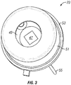
- the detector element 23 includes a chip providing the IR sensitive material forming the detector sensitive area 47.
- the chip, or sensitive area 47 is enclosed in a case 51 and mounted to a base 53.
- the case 51 has an appropriately-sized opening forming a window 49 in its top surface to allow the IR radiation to reach the sensitive area 47.
- the window 49 is covered by a material transparent to the radiation of interest, such as silicon or other suitable material.
- Leads 55 connect the detector element 23 to the microprocessor 17 and other circuitry, In one embodiment, a passive IR sensor known as a thermopile detector is used.
- Thermopile detectors respond to IR power emitted by an object in its field of view by producing a voltage that is proportional to incident power.
- One suitable thermopile detector is manufactured by Dexter Research Corporation (part number ST150).
- the thermopile detector used in one embodiment has a sensitive area 47 with dimensions of 1.5mm x 1.5mm and a window 49 of silicon.
- FIG. 4 a perspective view of the optical subsystem 13 and detector assembly 15 of Fig. 2 is shown, illustrating suitable locations on the various elements of the optical subsystem and detector assembly where temperature measurement devices may be located.
- Each element of the optical subsystem and detector assembly will emit electromagnetic radiation including IR radiation as a function of its temperature. In order to achieve the resolution necessary to produce an accurate measurement of the desired substance, the emission of each element in the system is preferably taken into account.
- Each element of the optical subsystem 13 within the field of view of the detector assembly 15, as well as the detector assembly 15, includes one or more suitable temperature sensing devices mounted at suitable locations on the element to accurately measure the temperature of the element.
- thermistors are used as the temperature measuring devices.
- a thermistor is a temperature dependent resistor typically composed of a semiconductor material. The resistance of a thermistor is inversely proportional to temperature, i.e., as the temperature increases, its resistance decreases. While other suitable temperature sensors can be used, thermocouples, for example, typically a thermistor provides a greater output voltage.
- thermistor 61 is located internally to the detector assembly 15 to measure the temperature of the cold junction where a thermopile detector is used.
- Thermistor 63 measures the temperature of the baffle 27.
- Thermistors 65 and 67 measure the temperature of mirror 29, and thermistors 7and 73 measure the temperature of mirror 31. Two thermistors are used for each mirror due to the size and mass of the mirrors.
- Thermistor 69 measures the temperature of the filters 33, 35 and of frame 37 assembly.
- Thermistor 75 measures the ambient room temperature.
- each element is matched with a set of predetermined calibration parameters stored in LUT 21 together with the temperature of detector 15, ambient temperature, and the temperature of body 11, to compensate for any perturbations in a substance concentration measurement due to the temperatures of the various optical subsystem and detector assembly elements.
- FIG. 5 a cross-sectional view of the detector assembly 15 and baffle 27 of the optical and detector apparatus of Fig. 2 is shown.
- detector element 23 is held by a retainer ring 81 in thermal contact with detector base 25.
- Baffle 27 is attached to the detector base 25 with fasteners 26, establishing good thermal contact between the detector element 23, ring 81, detector base 25, and baffle 27.
- the inner surface 83 of baffle 27 is preferably gold-coated and polished to create a mirror.
- the inner surface 83 of baffle 27 is designed to have a very low emissivity and high reflectivity.
- the shape of the inner surface 83 of baffle 27 is designed to minimize or prevent any reflection or multi-reflection of radiation from incident on the sensitive area 47 of the detector element 23.
- the inner surface 83 of baffle 27 forms a spherical surface, the center of the sphere coinciding with the center of the detector sensitive area 47, enclosing the detector element 23.
- An opening 95 is formed in the portion of the sphere over and opposite the sensitive area 47. The dimensions of the opening 95 are sufficient to allow the beam 45 (as shown in Fig. 2 ) to be incident on the sensitive area 47 and minimize or prevent any stray radiation from reaching the detector sensitive area 47.
- the front surface 89 of the detector element 23, the exposed surface 87 of retainer ring 81 and the exposed portion 85 of detector base 25 within the sphere are coated with a suitable material, such as a suitable black coating, for example, to create a radiation trap for any stray radiation.
- Thermistor 63 measures the temperature of the baffle 27 to enable compensation for its emission effects on the substance concentration measurements.
- Fig. 6 a cross-sectional view of the detector assembly 15 and baffle 27 of the optical and detector apparatus of Fig. 2 according to another embodiment is shown.
- mirrors 29 and 31 are preferably ninety-degree (90°) off-axis parabolic mirrors coated with gold or other suitable reflective material.
- the inner surface 83 of baffle 27 preferably forms a spherical surface having the center 99 of the sphere positioned off center with respect to the center 97 of the detector sensitive area 47.
- An opening 95 is formed in the portion of the sphere over and opposite the sensitive area 47.
- the position of the center 99 of the baffle opening 95 is also offset from the center 97 of the detector sensitive area 27 to provide maximum IR energy collection.
- the dimensions of the opening 95 are sufficient to allow the beam 45 (as shown in Fig. 2 ) to be incident on the detector sensitive area 47 and minimize or prevent any stray radiation from reaching the detector sensitive area 47.
Landscapes
- Physics & Mathematics (AREA)
- Spectroscopy & Molecular Physics (AREA)
- General Physics & Mathematics (AREA)
- Health & Medical Sciences (AREA)
- Life Sciences & Earth Sciences (AREA)
- General Health & Medical Sciences (AREA)
- Pathology (AREA)
- Chemical & Material Sciences (AREA)
- Analytical Chemistry (AREA)
- Biochemistry (AREA)
- Immunology (AREA)
- Emergency Medicine (AREA)
- Medical Informatics (AREA)
- Optics & Photonics (AREA)
- Biophysics (AREA)
- Engineering & Computer Science (AREA)
- Biomedical Technology (AREA)
- Heart & Thoracic Surgery (AREA)
- Toxicology (AREA)
- Molecular Biology (AREA)
- Surgery (AREA)
- Animal Behavior & Ethology (AREA)
- Public Health (AREA)
- Veterinary Medicine (AREA)
- Investigating Or Analysing Materials By Optical Means (AREA)
- Measurement Of The Respiration, Hearing Ability, Form, And Blood Characteristics Of Living Organisms (AREA)
- Measuring And Recording Apparatus For Diagnosis (AREA)
Description
- The present application relates generally to the non-invasive measurement of various substances in a body, such as the measurement of the concentration of glucose in the human body and, more specifically, to a far infrared detection system to analyze and determine, non-invasively, the concentration of a substance in a body. A device for measuring analyte concentration based on detected infrared radiation naturally emitted from a subject is known from
US 2005/0043630 . - Spectroscopic techniques using infrared ("IR") radiation are known in the prior art and have been widely used for non-invasive measurement of the concentration of substances of interest in a body. One area of particular interest is the use of these techniques for the non-invasive measurement of the concentration of glucose and other constituents of the human bloodstream.
- The infrared spectra includes the near infrared (approximately 1 to 3 microns), the middle infrared (approximately 3 to 6 microns), the far infrared (approximately 6 to 15 microns), and the extreme infrared (approximately 15 to 100 microns). Typical prior art glucose and other non-invasive blood constituent measuring devices operate in the near infrared regions where the absorption of infrared energy by glucose and other blood constituents is relatively low. However, it is known that glucose and other blood constituents have strong and distinguishable absorption spectra in both the middle and far infrared regions.
- It has been found in a far infrared detection system that the resolution of the system should be equivalent to 0.01°C to provide sufficiently accurate measurements. At this high level of accuracy, the blackbody emission of any component of the system (mirrors, filters, field limiters, detector, for example) can cause perturbations in the measurement. The conventional solution to such a problem is to cool the system to a cryogenic temperature (-180°C, for example), and have the system sealed and filled with dry nitrogen to avoid moisture accumulation. However, for a consumer product, such a solution is impractical and expensive.
- The present application discloses a far infrared system to analyze and determine, non-invasively, the concentration of a substance in a body. In accordance with one embodiment, an apparatus for the non-invasive measurement of a substance within a body includes a detector for sensing radiation emitted or remitted from a body, a human body, for example. An optical system is provided and aligned to focus IR radiation emitted by the body on a sensitive area of the detector.
- Each element of the system within the field of view of the detector and the detector itself has a temperature measuring device such as a thermistor attached to it for the purpose of measuring its temperature. For the detector to accurately measure the energy radiated by the body, the system is calibrated to compensate for the effect of the temperature of each element in the detector field of view. Using a heating or heating/cooling unit for each element separately, the temperature of each element can be varied for the purpose of calibration while the temperatures of the other elements of the system remain stable. This process is repeated many times in various ambient temperatures and various body temperatures in order to calibrate the effect of each element on the measurement in all ranges of conditions relevant for the measurement.
- This procedure is repeated for each element in the field of view of the detector yielding a look-up table ("LUT") representing the contribution of each element to the detector's measurement. The perturbations due to the temperature of each of the system elements are taken into account in each measurement, thereby enabling the system to obtain a high level of accuracy.
- During the creation and build-up of the LUT, it was found that the temperature effect of a baffle used to limit the field of view of the detector is 10:1 relative to the body reading. Calibration alone cannot compensate for such a significant effect.
- The solution in the far infrared region is to reduce the emissivity of the baffle by enhancing its reflectivity. However, enhancing the reflectivity of the baffle creates an additional problem of reflecting stray energy to the detector. A spherical baffle was designed with an internal surface, i.e., the surface of the baffle opposite the detector, that is polished and gold-plated to lower the emissivity. The baffle design eliminates any reflection or multiple reflections from reaching the sensitive area of the detector.
- The base plate that the detector and the baffle are mounted on and the baffle have substantially the same temperature as the detector, The base plate and the outer surface of the baffle are designed as a radiation trap having a dull black surface providing an emissivity of about 97%.
- The design of the system optics creates an image of the detector sensitive area on the surface of the body in order to collect the IR radiation emitted or remitted from the body. The area on the surface of the body subtended by the image of the detector sensitive area is critical since the detector is averaging the IR radiation emitted or remitted from this area.
- In accordance with another example the present optical apparatus comprises two changeable optical filters, a first mirror positioned to a first side of the optical filter, and a second mirror positioned to a second side of the optical filter opposite the first mirror. A detector is positioned to the second side of the optical filter. A baffle partially surrounds a sensitive surface of the detector. Temperature-measuring devices are configured to measure the temperature of the baffle, mirrors and filters. The first mirror is configured to receive IR radiation from a measured surface of the body, collimate the IR radiation to a beam, and reflect the collimated IR beam toward and through the optical filter. One of the optical filters is configured to filter out a portion of the collimated IR beam having wavelengths that fall outside a selected bandwidth, and the second optical filter is configured to filter out a portion of the collimated IR beam having wavelengths that fall within a selected bandwidth. The filters are changeable by a motorized mechanism, and each IR radiation measurement consists of at least one measurement with one filter and a second measurement with the second filter. The second mirror is configured to receive the collimated and filtered IR beam and reflect it toward the detector. The baffle is configured to block stray IR radiation so that it does not reach the detector sensitive area.
- Each of the two radiation measurements is then corrected to eliminate the effect of the emission of the system elements on the measurement. The ratio of the two radiation measurements after the correction and normalization for a black body reading is correlated to the concentration of the desired substance in the body, such as the concentration of glucose in the bloodstream of a human body, for example.
- An apparatus in accordance with the invention is defined in claim 1. A method in accordance with the invention is defined in
claim 12. - The following figures, in which like numerals indicate elements, form part of the present specification and are included to further demonstrate certain aspects of the present invention. The invention may be better understood by reference to one or more of these figures in combination with the detailed written description of specific embodiments presented herein.
-
Fig. 1 illustrates a block diagram of a system for the non-invasive measurement of the concentration of a substance in a body; -
Fig. 2 is a perspective view of the optical and detector apparatus ofFig. 1 illustrating the path of travel for electromagnetic rays between the body and the detector; -
Fig. 3 is a perspective view of the detector ofFigs. 1 and 2 ; -
Fig. 4 is a perspective view of the optical and detector apparatus ofFig. 2 , showing the locations on the various elements of the optical and detector apparatus of the temperature measurement devices; and -
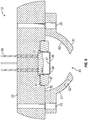
Figs. 5 and6 are cross-sectional views of the detector and baffle of the optical and detector apparatus shown inFig. 2 . - These and other embodiments of the present application will be discussed more fully in the description. The features, functions, and advantages can be achieved independently in various embodiments of the claimed invention, or may be combined in yet other embodiments.
- One or more illustrative embodiments are described below. Not all features of an actual implementation are necessarily described or shown for the sake of clarity.
- Referring now to
Fig. 1 , a block diagram of asystem 10 for the non-invasive measurement of the concentration of a substance in a body is shown. Infrared ("IR") radiation emitted or reflected from the surface of abody 11 is collected and collimated byoptics subsystem 13 and focused onIR detector assembly 15. Thebody 11 is the source of the IR radiation being measured by thesystem 10. Thebody 11 is typically a portion of a surface of a body of interest, such as a human body, for example. Theoptical subsystem 13 includes at least twochangeable filters Fig. 2 , that allow two different wavelength bandwidth signals, the first including a characteristic wavelength of a desired substance, such as glucose, for example, to be measured, the second being a portion of the emitted radiation not including the substance characteristic wavelength to be used as a reference signal. - The
detector assembly 15 senses both signals and provides an output voltage that is proportional to the intensity of each of the two signal measurements to themicroprocessor 17. Temperature sensors, as shown inFig. 4 , provide the temperatures of the various optical subsystem and detector assembly components and the ambient temperature to themicroprocessor 17 vialines LUT 21. - The
microprocessor 17 uses the set of predetermined calibration parameters to correct each of the two radiation measurements to eliminate the effect of the emission of the system elements on the measurement. The ratio of the two radiation measurements after the correction and normalization for a black body reading is correlated to the concentration of the desired substance in the body, such as the concentration of glucose in the bloodstream of a human body, for example. The result is then provided to anoutput device 19, such as an LCD or LED video monitor, for example. - Referring now also to
Fig. 2 , a schematic perspective view of the configuration of the optical and detector components of thesystem 10 shown inFig. 1 , illustrating the path of travel for IR rays between thebody 11 and thedetector 15 is shown, Thedetector 15 includes thedetector element 23,detector base 25 and abaffle 27. The configuration of the optical and detector components is designed such that animage 12 of the sensitive oractive area 47 of the detector 15 (as shown inFig. 3 ) is created at thebody 11 on the focal plane ofmirror 31. - The area of
image 12 preferably has a diameter approximately 6 mm, IR radiation emitted from or reflected by thebody 11 atimage 12 inbeam 41 is collected and collimated bymirror 31. The IR radiation is reflected bymirror 31 and propagated to mirror 29 in a collimatedbeam 43 of parallel rays viafilter 33 orfilter 35. The focal plane ofmirror 29 is located at the surface of thesensitive area 47 of thedetector assembly 15. Thebeam 43 reachingmirror 29 is reflected and propagated asbeam 45 and focused at the focal plane ofmirror 29 incident on thedetector assembly 15sensitive area 47. - The
detector assembly 15 is partially surrounded by abaffle 27 on the side facing themirror 29. Thebaffle 27 insures that substantially onlybeam 45 is incident only on thesensitive area 47.Baffle 27 also blocks any stray radiation from reaching thesensitive area 47 ofdetector assembly 15. Thus, theoptical subsystem 13 is aligned such that theimage 12 is positioned at the surface ofbody 11 and thebeam 41 of IR radiation is incident on thesensitive area 47 ofdetector assembly 15 viamirror 31,filter 33 orfilter 35 andmirror 29. - In one embodiment, mirrors 29 and 31 are preferably ninety-degree (90°) off-axis parabolic mirrors coated with gold or other suitable reflective material. Preferably
mirror 29 will have a focal length of about one (1) inch andmirror 31 will have a focal length of about three (3) inches. Other suitably designed reflective mirrors may be used for theoptical subsystem 13 such as ellipsoid mirrors or a combination of ellipsoid and hyperbolic mirrors, for example. -
Filter 33 andfilter 35 are mounted inframe 37,frame 37 being positioned betweenmirror 29 andmirror 31. Thefilters beam 43 using a suitable driving mechanism, such as a motor or pneumatic pressure, for example, coupled toframe 37. In one embodiment,motor 39 is coupled to theframe 37 and positions theframe 37 between themirror 29 andmirror 31 such that the desiredfilter beam 43. One of the filters,filter 33, for example, will preferably be a narrow band filter passing the wavelengths of the spectral characteristic of the substance being measured. The other filter,filter 35, for example, will preferably be a narrow band filter passing those wavelengths of a spectral characteristic not sensitive to the substance being measured. For example, in some embodiments, filter 33 will limit the bandwidth to that region of the spectrum where there is no emission for the substance being measured (for glucose, for example, the bandwidth would be 10.5µ-15µ), whilefilter 35 would have a bandwidth characteristic of the emission of the substance being measured (for glucose, the bandwidth would be 8.5µ-10.5µ). - Referring now also to
Fig. 3 , a perspective view of thedetector element 23 shown in Figs. and 2 is illustrated. Any suitable IR detector responsive to the desired wavelengths of interest may be used. Thedetector element 23 includes a chip providing the IR sensitive material forming the detectorsensitive area 47. The chip, orsensitive area 47, is enclosed in acase 51 and mounted to abase 53. Thecase 51 has an appropriately-sized opening forming awindow 49 in its top surface to allow the IR radiation to reach thesensitive area 47. Thewindow 49 is covered by a material transparent to the radiation of interest, such as silicon or other suitable material. Leads 55 connect thedetector element 23 to themicroprocessor 17 and other circuitry, In one embodiment, a passive IR sensor known as a thermopile detector is used. Thermopile detectors respond to IR power emitted by an object in its field of view by producing a voltage that is proportional to incident power. One suitable thermopile detector is manufactured by Dexter Research Corporation (part number ST150). The thermopile detector used in one embodiment has asensitive area 47 with dimensions of 1.5mm x 1.5mm and awindow 49 of silicon. - Referring now also to
Fig. 4 , a perspective view of theoptical subsystem 13 anddetector assembly 15 ofFig. 2 is shown, illustrating suitable locations on the various elements of the optical subsystem and detector assembly where temperature measurement devices may be located. Each element of the optical subsystem and detector assembly will emit electromagnetic radiation including IR radiation as a function of its temperature. In order to achieve the resolution necessary to produce an accurate measurement of the desired substance, the emission of each element in the system is preferably taken into account. - Each element of the
optical subsystem 13 within the field of view of thedetector assembly 15, as well as thedetector assembly 15, includes one or more suitable temperature sensing devices mounted at suitable locations on the element to accurately measure the temperature of the element. In one embodiment, thermistors are used as the temperature measuring devices. A thermistor is a temperature dependent resistor typically composed of a semiconductor material. The resistance of a thermistor is inversely proportional to temperature, i.e., as the temperature increases, its resistance decreases. While other suitable temperature sensors can be used, thermocouples, for example, typically a thermistor provides a greater output voltage. - In the embodiment shown in
Fig. 4 ,thermistor 61 is located internally to thedetector assembly 15 to measure the temperature of the cold junction where a thermopile detector is used.Thermistor 63 measures the temperature of thebaffle 27. Thermistors 65 and 67 measure the temperature ofmirror 29, andthermistors 7and 73 measure the temperature ofmirror 31. Two thermistors are used for each mirror due to the size and mass of the mirrors.Thermistor 69 measures the temperature of thefilters frame 37 assembly.Thermistor 75 measures the ambient room temperature. The temperature of each element is matched with a set of predetermined calibration parameters stored inLUT 21 together with the temperature ofdetector 15, ambient temperature, and the temperature ofbody 11, to compensate for any perturbations in a substance concentration measurement due to the temperatures of the various optical subsystem and detector assembly elements. - Referring now also to
Fig. 5 , a cross-sectional view of thedetector assembly 15 and baffle 27 of the optical and detector apparatus ofFig. 2 is shown. In the illustrated embodiment,detector element 23 is held by aretainer ring 81 in thermal contact withdetector base 25.Baffle 27 is attached to thedetector base 25 withfasteners 26, establishing good thermal contact between thedetector element 23,ring 81,detector base 25, andbaffle 27. Theinner surface 83 ofbaffle 27 is preferably gold-coated and polished to create a mirror. Theinner surface 83 ofbaffle 27 is designed to have a very low emissivity and high reflectivity. The shape of theinner surface 83 ofbaffle 27 is designed to minimize or prevent any reflection or multi-reflection of radiation from incident on thesensitive area 47 of thedetector element 23. - In one embodiment, the
inner surface 83 ofbaffle 27 forms a spherical surface, the center of the sphere coinciding with the center of the detectorsensitive area 47, enclosing thedetector element 23. Anopening 95 is formed in the portion of the sphere over and opposite thesensitive area 47. The dimensions of theopening 95 are sufficient to allow the beam 45 (as shown inFig. 2 ) to be incident on thesensitive area 47 and minimize or prevent any stray radiation from reaching the detectorsensitive area 47. Thefront surface 89 of thedetector element 23, the exposedsurface 87 ofretainer ring 81 and the exposedportion 85 ofdetector base 25 within the sphere are coated with a suitable material, such as a suitable black coating, for example, to create a radiation trap for any stray radiation.Thermistor 63 measures the temperature of thebaffle 27 to enable compensation for its emission effects on the substance concentration measurements. - Referring now also to
Fig. 6 , a cross-sectional view of thedetector assembly 15 and baffle 27 of the optical and detector apparatus ofFig. 2 according to another embodiment is shown. In this embodiment, as described above with reference to paragraph 0028 andFig. 2 , mirrors 29 and 31 are preferably ninety-degree (90°) off-axis parabolic mirrors coated with gold or other suitable reflective material. Theinner surface 83 ofbaffle 27 preferably forms a spherical surface having thecenter 99 of the sphere positioned off center with respect to thecenter 97 of the detectorsensitive area 47. Anopening 95 is formed in the portion of the sphere over and opposite thesensitive area 47. Since the maximum of the IR energy distribution of an off-axis mirror is off center, the position of thecenter 99 of thebaffle opening 95 is also offset from thecenter 97 of the detectorsensitive area 27 to provide maximum IR energy collection. The dimensions of theopening 95 are sufficient to allow the beam 45 (as shown inFig. 2 ) to be incident on the detectorsensitive area 47 and minimize or prevent any stray radiation from reaching the detectorsensitive area 47. - Although the invention has been described in terms of certain embodiments, other embodiments that are apparent to those of ordinary skill in the art, including embodiments which do not provide all of the features and advantages set forth herein, are also within the scope of this invention. Accordingly, the scope of the invention is defined by the claims that follow.
Claims (15)
- Apparatus for non-invasive measurement of a concentration of a substance within a body, comprising:a detector (23) configured to sense radiation (41, 43, 45) emitted or remitted from a body;an optical subsystem (13) configured to focus the radiation on a sensitive area (47) of the detector; andone or more temperature sensors (61-75) attached to one or more of a plurality of elements (27, 29, 31, 37) of the optical subsystem and one or more additional temperature sensors attached to the detector (23),the one or more temperature sensors being configured to measure the temperature of the one or more elements of the optical subsystem,the one or more additional temperature sensors being configured to measure the temperature of the detector, andthe apparatus being configured to correct a value of the sensed radiation for the effects of the emission of each of the detector and the one or more elements of the optical subsystem using predetermined calibration parameters determined from the measured temperatures of the one or more elements of the optical subsystem and of the detector and to measure the concentration of the substance using the corrected value of the sensed radiation.
- The apparatus of claim 1, wherein:a baffle (27) configured to minimize the incidence of stray radiation on the detector sensitive area is attached to and in thermal contact with the detector, the baffle being disposed to at least partially surround the detector sensitive area (27); andan interior surface (83) of the baffle opposite the detector is formed to minimize the incidence of radiation reflection or multi-reflection on the detector sensitive area and has a high reflectivity and low emissivity.
- The apparatus of claim 2, having one or more of the following features:the interior surface (83) of the baffle constitutes a portion of a sphere surrounding the detector, a portion of the baffle above and opposite the sensitive area of the detector having an opening (95) allowing the radiation to reach the sensitive area of the detector, optionally havingan exterior surface (91) of the baffle coated with a black coating for absorbing stray radiation.
- The apparatus of claim 1, 2 or 3 wherein the detector comprises a thermopile detector or other infrared energy sensor, e.g. a far infrared sensor.
- The apparatus of claim 4, having:a first filter (33) passing wavelengths characteristic of the substance being measured and a second filter (35) passing wavelengths of a spectral characteristic not sensitive to the substance being measured; anda movable frame (37) on which the first and second filters are mounted for switching between positions intercepting the radiation (43).
- The apparatus of claim 5, wherein the first filter (33) passes wavelengths of 8.5-10.5 µm and the second filter (35) passes wavelengths of 10.5-15 µm.
- The apparatus of any preceding claim, wherein the optical subsystem has one or more mirrors (29, 31) configured to focus the radiation on the sensitive area of the detector;
optionally having at least two mirrors including at least one attenuation filter disposed between the two mirrors for attenuating radiation in a selected wavelength band;
optionally having two attenuation filters (33, 35) configured to attenuate radiation in selected wavelength bands mounted on a moveable frame (37) disposed between the two mirrors (29, 31) configured to focus the radiation on the sensitive area of the detector. - The apparatus of claim 7, comprising at least two ninety degree (90°) off-axis parabolic mirrors.
- The apparatus of any preceding claim, further comprising a temperature sensor for measuring ambient temperature.
- The apparatus of any preceding claim, wherein the one or more temperature sensors configured to measure the temperature of the one or more elements of the optical subsystem, the one or more additional temperature sensors configured to measure the temperature of the detector, and the temperature sensor for measuring ambient temperature are thermistors.
- The apparatus of any preceding claim, wherein the temperature of one or more of the plurality of optical subsystem elements and the temperature of the detector are matched with a set of predetermined compensation parameters stored in a look-up table (21) for compensating for an effect on the non-invasive measurement of the temperature of each of the one or more of the plurality of elements and the detector, an ambient temperature and a temperature measured at a surface of the body.
- A method of noninvasively measuring a concentration of a substance in a body using an apparatus including a detector and an optical system, the method comprising the steps of:detecting an infrared radiation value emitted by the body in a wavelength range including at least one wavelength characteristic of the substance;measuring the temperature of the detector and one or more components of the optical system;correlating the temperatures of the detector and the one or more components of the optical system with a set of predetermined calibration parameters and correcting the detected infrared radiation value for the effects of the emission of each of the detector and the one or more components of the optical system using the predetermined calibration parameters; andmeasuring the concentration of the substance using the detected infrared radiation value as corrected by the predetermined calibration parameters correlated with the measured temperatures.
- The method of claim 12, further comprising the step of measuring the ambient temperature optionally comprising measuring the temperature of the body.
- The method of claim 12 or 13, further comprising the step of:limiting the wavelength range of the detected infrared radiation value;optionally comprising limiting the wavelength range of the detected infrared radiation value to a first wavelength range including at least one wavelength characteristic of the substance to provide a first detected radiation value, and limiting the wavelength range of the detected infrared radiation value to a second wavelength range wherein wavelengths characteristic of the substance are minimized to provide a second detected radiation value;optionally comprising correcting the first and second detected radiation values for the effects of the emission of each of the detector and the one or more components of the optical system, normalizing the first and second detected radiation values for a blackbody reading, and correlating the ratio of the first and second detected radiation values to the concentration of the substance in the body.
- The method of claim 14, wherein the first wavelength range is 8.5 µm to 10.0 µm, the second wavelength range is 10.5 µm to 15.0 µm, and the substance is glucose.
Applications Claiming Priority (2)
| Application Number | Priority Date | Filing Date | Title |
|---|---|---|---|
| US12/607,903 US8611975B2 (en) | 2009-10-28 | 2009-10-28 | Apparatus and method for non-invasive measurement of a substance within a body |
| PCT/US2010/050901 WO2011056328A1 (en) | 2009-10-28 | 2010-09-30 | Apparatus and method for non-invasive measurement of a substance within a body |
Publications (2)
| Publication Number | Publication Date |
|---|---|
| EP2493369A1 EP2493369A1 (en) | 2012-09-05 |
| EP2493369B1 true EP2493369B1 (en) | 2020-11-11 |
Family
ID=43898995
Family Applications (1)
| Application Number | Title | Priority Date | Filing Date |
|---|---|---|---|
| EP10765885.8A Active EP2493369B1 (en) | 2009-10-28 | 2010-09-30 | Apparatus and method for non-invasive measurement of a substance within a body |
Country Status (10)
| Country | Link |
|---|---|
| US (1) | US8611975B2 (en) |
| EP (1) | EP2493369B1 (en) |
| JP (1) | JP5491636B2 (en) |
| CN (1) | CN102665534B (en) |
| AU (1) | AU2010315808B2 (en) |
| BR (1) | BR112012011449A2 (en) |
| CA (1) | CA2779382C (en) |
| MX (1) | MX2012004945A (en) |
| RU (1) | RU2511405C2 (en) |
| WO (1) | WO2011056328A1 (en) |
Families Citing this family (13)
| Publication number | Priority date | Publication date | Assignee | Title |
|---|---|---|---|---|
| JP5915470B2 (en) * | 2012-08-31 | 2016-05-11 | 株式会社島津製作所 | Spectrophotometer |
| EP3013229A2 (en) * | 2013-06-23 | 2016-05-04 | GlucoVista Inc. | Substance concentration measurement using a cooling device with endothermic reaction |
| EP3091902B1 (en) | 2014-01-10 | 2020-03-25 | GlucoVista, Inc. | Non-invasive system and method for measuring a substance concentration |
| JP6966200B2 (en) | 2014-06-19 | 2021-11-10 | グルコビスタ・インコーポレイテッド | Substance concentration monitoring device and method |
| US10588552B2 (en) | 2014-06-19 | 2020-03-17 | Glucovista Inc. | Substance concentration analysis methods and apparatuses |
| CN107427232B (en) * | 2015-03-16 | 2021-03-02 | 格鲁科威斯塔公司 | Substance concentration correction system and method |
| JP6462594B2 (en) * | 2015-04-30 | 2019-01-30 | オリンパス株式会社 | Imaging apparatus, image processing apparatus, and image processing method |
| US10585291B2 (en) * | 2017-04-28 | 2020-03-10 | Yonatan Gerlitz | Eye safety system for lasers |
| CN110662481B (en) | 2017-05-19 | 2023-01-03 | 格鲁科威斯塔公司 | Substance concentration NIR monitoring apparatus and method |
| JP2019037752A (en) * | 2017-08-23 | 2019-03-14 | 株式会社リコー | Measuring device and measuring method |
| CN107589692A (en) * | 2017-08-25 | 2018-01-16 | 苏州麦喆思科电子有限公司 | A kind of automatic range control device of radiator |
| EP4037560B1 (en) * | 2019-09-30 | 2025-03-26 | Gluco Tera Tech Ag | Non-invasive testing of glucose |
| EP4111947A4 (en) | 2020-02-28 | 2023-08-02 | Sony Group Corporation | DEVICE FOR GATHERING BIOLOGICAL INFORMATION, SYSTEM FOR GATHERING BIOLOGICAL INFORMATION AND METHOD FOR GATHERING BIOLOGICAL INFORMATION |
Family Cites Families (34)
| Publication number | Priority date | Publication date | Assignee | Title |
|---|---|---|---|---|
| US3770958A (en) * | 1972-01-05 | 1973-11-06 | Honeywell Inc | Infrared radiation detection by a matched system |
| EP0160768B1 (en) | 1984-05-04 | 1989-05-03 | Kurabo Industries Ltd. | Spectrophotometric apparatus for the non-invasive determination of glucose in body tissues |
| US4786169A (en) * | 1985-08-08 | 1988-11-22 | Nicolet Instrument Corporation | Optical analytical instrument for testing the transmission and reflection of a sample |
| US5237178A (en) * | 1990-06-27 | 1993-08-17 | Rosenthal Robert D | Non-invasive near-infrared quantitative measurement instrument |
| US5370114A (en) * | 1992-03-12 | 1994-12-06 | Wong; Jacob Y. | Non-invasive blood chemistry measurement by stimulated infrared relaxation emission |
| US5515847A (en) * | 1993-01-28 | 1996-05-14 | Optiscan, Inc. | Self-emission noninvasive infrared spectrophotometer |
| US5615672A (en) * | 1993-01-28 | 1997-04-01 | Optiscan, Inc. | Self-emission noninvasive infrared spectrophotometer with body temperature compensation |
| US5313941A (en) * | 1993-01-28 | 1994-05-24 | Braig James R | Noninvasive pulsed infrared spectrophotometer |
| JPH08313348A (en) * | 1995-05-16 | 1996-11-29 | Kanagawa Kagaku Gijutsu Akad | Infrared light time response measuring device |
| US5666956A (en) * | 1996-05-20 | 1997-09-16 | Buchert; Janusz Michal | Instrument and method for non-invasive monitoring of human tissue analyte by measuring the body's infrared radiation |
| US5900632A (en) * | 1997-03-12 | 1999-05-04 | Optiscan Biomedical Corporation | Subsurface thermal gradient spectrometry |
| JP3794137B2 (en) * | 1997-11-26 | 2006-07-05 | 松下電器産業株式会社 | Infrared detector and radiation thermometer using the same |
| US5895918A (en) * | 1998-04-15 | 1999-04-20 | Lockhead Martin Energy Systems, Inc. | Apparatus for and method of performing spectroscopic analysis on an article |
| JP2002533142A (en) * | 1998-12-23 | 2002-10-08 | メディスペクトラ, インコーポレイテッド | Systems and methods for optical testing of samples |
| WO2001082786A2 (en) * | 2000-05-03 | 2001-11-08 | Flock Stephen T | Optical imaging of subsurface anatomical structures and biomolecules |
| US6647350B1 (en) * | 2000-06-02 | 2003-11-11 | Exactus, Inc. | Radiometric temperature measurement system |
| WO2003012486A2 (en) * | 2001-08-02 | 2003-02-13 | Jonathan Gerlitz | Non-invasive glucose-meter |
| US6998247B2 (en) * | 2002-03-08 | 2006-02-14 | Sensys Medical, Inc. | Method and apparatus using alternative site glucose determinations to calibrate and maintain noninvasive and implantable analyzers |
| JP3743394B2 (en) * | 2002-05-31 | 2006-02-08 | 株式会社村田製作所 | Infrared sensor and electronic device using the same |
| RU2233111C1 (en) * | 2002-12-25 | 2004-07-27 | ШМЕЛЕВ Владимир Михайлович | Apparatus for non-invasive monitoring of glucose concentration (variants) |
| KR100580622B1 (en) * | 2003-03-19 | 2006-05-16 | 삼성전자주식회사 | Non-invasive blood component measurement method and apparatus |
| US6992772B2 (en) * | 2003-06-19 | 2006-01-31 | Optix Lp | Method and apparatus for optical sampling to reduce interfering variances |
| US20050043630A1 (en) * | 2003-08-21 | 2005-02-24 | Buchert Janusz Michal | Thermal Emission Non-Invasive Analyte Monitor |
| US6949070B2 (en) * | 2003-08-21 | 2005-09-27 | Ishler Larry W | Non-invasive blood glucose monitoring system |
| US7342082B2 (en) * | 2004-12-17 | 2008-03-11 | 3M Innovative Properties Company | Soluble polymers as amine capture agents and methods |
| JP3590053B1 (en) | 2004-02-24 | 2004-11-17 | 株式会社日立製作所 | Blood glucose measurement device |
| JP2006115948A (en) * | 2004-10-19 | 2006-05-11 | Hitachi Ltd | Blood glucose level measuring device |
| EP1892521A1 (en) * | 2005-06-07 | 2008-02-27 | Omron Healthcare Co., Ltd. | Biometric information measuring sensor |
| JP2007105329A (en) * | 2005-10-14 | 2007-04-26 | Hitachi Ltd | Blood glucose level measuring device and metabolic rate measuring device |
| US20080269580A1 (en) * | 2005-12-22 | 2008-10-30 | Koninklijke Philips Electronics, N.V. | System for Non-Invasive Measurement of Bloold Glucose Concentration |
| JP2007195653A (en) * | 2006-01-25 | 2007-08-09 | Matsushita Electric Ind Co Ltd | Radiation spectral densitometer |
| CA2651003A1 (en) * | 2006-02-22 | 2007-09-07 | Vivum Nexus Llc | Method and device for analyte measurement |
| US8364218B2 (en) * | 2008-02-11 | 2013-01-29 | Glucovista, Inc. | Apparatus and method for non-invasive measurement of the concentration of a substance in subjects blood |
| US8401604B2 (en) * | 2008-04-11 | 2013-03-19 | Glucovista, Llc | Apparatus and methods for non-invasive measurement of a substance within a body |
-
2009
- 2009-10-28 US US12/607,903 patent/US8611975B2/en active Active
-
2010
- 2010-09-30 RU RU2012121558/14A patent/RU2511405C2/en not_active IP Right Cessation
- 2010-09-30 CN CN201080048921.5A patent/CN102665534B/en active Active
- 2010-09-30 AU AU2010315808A patent/AU2010315808B2/en not_active Ceased
- 2010-09-30 MX MX2012004945A patent/MX2012004945A/en unknown
- 2010-09-30 JP JP2012536828A patent/JP5491636B2/en active Active
- 2010-09-30 CA CA2779382A patent/CA2779382C/en not_active Expired - Fee Related
- 2010-09-30 EP EP10765885.8A patent/EP2493369B1/en active Active
- 2010-09-30 BR BR112012011449A patent/BR112012011449A2/en not_active IP Right Cessation
- 2010-09-30 WO PCT/US2010/050901 patent/WO2011056328A1/en not_active Ceased
Non-Patent Citations (1)
| Title |
|---|
| LAURA R BALLEW: "A Microwave Radiometer System for Use in Biomedical Applications", 31 December 2006 (2006-12-31), XP055372377, Retrieved from the Internet <URL:https://baylor-ir.tdl.org/baylor-ir/bitstream/handle/2104/4956/Laura_Broyles_Masters.pdf?sequence=1> [retrieved on 20170512] * |
Also Published As
| Publication number | Publication date |
|---|---|
| BR112012011449A2 (en) | 2017-09-19 |
| JP5491636B2 (en) | 2014-05-14 |
| RU2511405C2 (en) | 2014-04-10 |
| WO2011056328A1 (en) | 2011-05-12 |
| CA2779382C (en) | 2016-05-10 |
| CN102665534A (en) | 2012-09-12 |
| AU2010315808B2 (en) | 2014-05-29 |
| US20110098542A1 (en) | 2011-04-28 |
| AU2010315808A1 (en) | 2012-05-10 |
| MX2012004945A (en) | 2012-11-21 |
| JP2013509239A (en) | 2013-03-14 |
| US8611975B2 (en) | 2013-12-17 |
| RU2012121558A (en) | 2013-12-10 |
| EP2493369A1 (en) | 2012-09-05 |
| CN102665534B (en) | 2016-05-04 |
| CA2779382A1 (en) | 2011-05-12 |
Similar Documents
| Publication | Publication Date | Title |
|---|---|---|
| CA2779382C (en) | Apparatus and method for non-invasive measurement of a substance within a body | |
| US11141082B2 (en) | Method for non-invasive analysis of a substance concentration within a body | |
| US5823966A (en) | Non-invasive continuous blood glucose monitoring | |
| JP6389444B2 (en) | Thermal radiation thermometer | |
| EP2276406B1 (en) | Apparatus and methods for non-invasive measurement of a substance within a body | |
| US11280726B2 (en) | Assembly and method for measuring a substance concentration in a gaseous medium by means of absorption spectroscopy | |
| US9052235B2 (en) | Infrared sensor and use of same | |
| JP2001503999A (en) | Measurement of tissue analytes by infrared | |
| US20150241347A1 (en) | Nondispersive infrared micro-optics sensor for blood alcohol concentration measurements | |
| US8903466B2 (en) | Apparatus and method for non-invasive measurement of a substance within a body | |
| US5694930A (en) | Device for qualitative and/or quantative analysis of a sample | |
| JP2023535745A (en) | Spectrometer apparatus and method for measuring optical radiation | |
| Hartwig et al. | A highly sensitive IR-optical sensor for ethylene-monitoring |
Legal Events
| Date | Code | Title | Description |
|---|---|---|---|
| PUAI | Public reference made under article 153(3) epc to a published international application that has entered the european phase |
Free format text: ORIGINAL CODE: 0009012 |
|
| 17P | Request for examination filed |
Effective date: 20120423 |
|
| AK | Designated contracting states |
Kind code of ref document: A1 Designated state(s): AL AT BE BG CH CY CZ DE DK EE ES FI FR GB GR HR HU IE IS IT LI LT LU LV MC MK MT NL NO PL PT RO SE SI SK SM TR |
|
| DAX | Request for extension of the european patent (deleted) | ||
| STAA | Information on the status of an ep patent application or granted ep patent |
Free format text: STATUS: EXAMINATION IS IN PROGRESS |
|
| 17Q | First examination report despatched |
Effective date: 20180209 |
|
| GRAP | Despatch of communication of intention to grant a patent |
Free format text: ORIGINAL CODE: EPIDOSNIGR1 |
|
| STAA | Information on the status of an ep patent application or granted ep patent |
Free format text: STATUS: GRANT OF PATENT IS INTENDED |
|
| INTG | Intention to grant announced |
Effective date: 20200529 |
|
| GRAS | Grant fee paid |
Free format text: ORIGINAL CODE: EPIDOSNIGR3 |
|
| GRAA | (expected) grant |
Free format text: ORIGINAL CODE: 0009210 |
|
| STAA | Information on the status of an ep patent application or granted ep patent |
Free format text: STATUS: THE PATENT HAS BEEN GRANTED |
|
| RIN1 | Information on inventor provided before grant (corrected) |
Inventor name: GERLITZ, YONATAN |
|
| RAP1 | Party data changed (applicant data changed or rights of an application transferred) |
Owner name: GLUCOVISTA INC. |
|
| AK | Designated contracting states |
Kind code of ref document: B1 Designated state(s): AL AT BE BG CH CY CZ DE DK EE ES FI FR GB GR HR HU IE IS IT LI LT LU LV MC MK MT NL NO PL PT RO SE SI SK SM TR |
|
| REG | Reference to a national code |
Ref country code: GB Ref legal event code: FG4D |
|
| REG | Reference to a national code |
Ref country code: CH Ref legal event code: EP |
|
| REG | Reference to a national code |
Ref country code: AT Ref legal event code: REF Ref document number: 1332664 Country of ref document: AT Kind code of ref document: T Effective date: 20201115 |
|
| REG | Reference to a national code |
Ref country code: DE Ref legal event code: R096 Ref document number: 602010065894 Country of ref document: DE |
|
| REG | Reference to a national code |
Ref country code: IE Ref legal event code: FG4D |
|
| REG | Reference to a national code |
Ref country code: NL Ref legal event code: MP Effective date: 20201111 |
|
| REG | Reference to a national code |
Ref country code: AT Ref legal event code: MK05 Ref document number: 1332664 Country of ref document: AT Kind code of ref document: T Effective date: 20201111 |
|
| PG25 | Lapsed in a contracting state [announced via postgrant information from national office to epo] |
Ref country code: GR Free format text: LAPSE BECAUSE OF FAILURE TO SUBMIT A TRANSLATION OF THE DESCRIPTION OR TO PAY THE FEE WITHIN THE PRESCRIBED TIME-LIMIT Effective date: 20210212 Ref country code: NO Free format text: LAPSE BECAUSE OF FAILURE TO SUBMIT A TRANSLATION OF THE DESCRIPTION OR TO PAY THE FEE WITHIN THE PRESCRIBED TIME-LIMIT Effective date: 20210211 Ref country code: PT Free format text: LAPSE BECAUSE OF FAILURE TO SUBMIT A TRANSLATION OF THE DESCRIPTION OR TO PAY THE FEE WITHIN THE PRESCRIBED TIME-LIMIT Effective date: 20210311 Ref country code: FI Free format text: LAPSE BECAUSE OF FAILURE TO SUBMIT A TRANSLATION OF THE DESCRIPTION OR TO PAY THE FEE WITHIN THE PRESCRIBED TIME-LIMIT Effective date: 20201111 |
|
| PG25 | Lapsed in a contracting state [announced via postgrant information from national office to epo] |
Ref country code: SE Free format text: LAPSE BECAUSE OF FAILURE TO SUBMIT A TRANSLATION OF THE DESCRIPTION OR TO PAY THE FEE WITHIN THE PRESCRIBED TIME-LIMIT Effective date: 20201111 Ref country code: PL Free format text: LAPSE BECAUSE OF FAILURE TO SUBMIT A TRANSLATION OF THE DESCRIPTION OR TO PAY THE FEE WITHIN THE PRESCRIBED TIME-LIMIT Effective date: 20201111 Ref country code: LV Free format text: LAPSE BECAUSE OF FAILURE TO SUBMIT A TRANSLATION OF THE DESCRIPTION OR TO PAY THE FEE WITHIN THE PRESCRIBED TIME-LIMIT Effective date: 20201111 Ref country code: IS Free format text: LAPSE BECAUSE OF FAILURE TO SUBMIT A TRANSLATION OF THE DESCRIPTION OR TO PAY THE FEE WITHIN THE PRESCRIBED TIME-LIMIT Effective date: 20210311 Ref country code: AT Free format text: LAPSE BECAUSE OF FAILURE TO SUBMIT A TRANSLATION OF THE DESCRIPTION OR TO PAY THE FEE WITHIN THE PRESCRIBED TIME-LIMIT Effective date: 20201111 Ref country code: BG Free format text: LAPSE BECAUSE OF FAILURE TO SUBMIT A TRANSLATION OF THE DESCRIPTION OR TO PAY THE FEE WITHIN THE PRESCRIBED TIME-LIMIT Effective date: 20210211 |
|
| REG | Reference to a national code |
Ref country code: LT Ref legal event code: MG9D |
|
| PG25 | Lapsed in a contracting state [announced via postgrant information from national office to epo] |
Ref country code: HR Free format text: LAPSE BECAUSE OF FAILURE TO SUBMIT A TRANSLATION OF THE DESCRIPTION OR TO PAY THE FEE WITHIN THE PRESCRIBED TIME-LIMIT Effective date: 20201111 |
|
| PG25 | Lapsed in a contracting state [announced via postgrant information from national office to epo] |
Ref country code: LT Free format text: LAPSE BECAUSE OF FAILURE TO SUBMIT A TRANSLATION OF THE DESCRIPTION OR TO PAY THE FEE WITHIN THE PRESCRIBED TIME-LIMIT Effective date: 20201111 Ref country code: SK Free format text: LAPSE BECAUSE OF FAILURE TO SUBMIT A TRANSLATION OF THE DESCRIPTION OR TO PAY THE FEE WITHIN THE PRESCRIBED TIME-LIMIT Effective date: 20201111 Ref country code: RO Free format text: LAPSE BECAUSE OF FAILURE TO SUBMIT A TRANSLATION OF THE DESCRIPTION OR TO PAY THE FEE WITHIN THE PRESCRIBED TIME-LIMIT Effective date: 20201111 Ref country code: SM Free format text: LAPSE BECAUSE OF FAILURE TO SUBMIT A TRANSLATION OF THE DESCRIPTION OR TO PAY THE FEE WITHIN THE PRESCRIBED TIME-LIMIT Effective date: 20201111 Ref country code: CZ Free format text: LAPSE BECAUSE OF FAILURE TO SUBMIT A TRANSLATION OF THE DESCRIPTION OR TO PAY THE FEE WITHIN THE PRESCRIBED TIME-LIMIT Effective date: 20201111 Ref country code: EE Free format text: LAPSE BECAUSE OF FAILURE TO SUBMIT A TRANSLATION OF THE DESCRIPTION OR TO PAY THE FEE WITHIN THE PRESCRIBED TIME-LIMIT Effective date: 20201111 |
|
| REG | Reference to a national code |
Ref country code: DE Ref legal event code: R097 Ref document number: 602010065894 Country of ref document: DE |
|
| PG25 | Lapsed in a contracting state [announced via postgrant information from national office to epo] |
Ref country code: DK Free format text: LAPSE BECAUSE OF FAILURE TO SUBMIT A TRANSLATION OF THE DESCRIPTION OR TO PAY THE FEE WITHIN THE PRESCRIBED TIME-LIMIT Effective date: 20201111 |
|
| PLBE | No opposition filed within time limit |
Free format text: ORIGINAL CODE: 0009261 |
|
| STAA | Information on the status of an ep patent application or granted ep patent |
Free format text: STATUS: NO OPPOSITION FILED WITHIN TIME LIMIT |
|
| 26N | No opposition filed |
Effective date: 20210812 |
|
| PG25 | Lapsed in a contracting state [announced via postgrant information from national office to epo] |
Ref country code: IT Free format text: LAPSE BECAUSE OF FAILURE TO SUBMIT A TRANSLATION OF THE DESCRIPTION OR TO PAY THE FEE WITHIN THE PRESCRIBED TIME-LIMIT Effective date: 20201111 Ref country code: AL Free format text: LAPSE BECAUSE OF FAILURE TO SUBMIT A TRANSLATION OF THE DESCRIPTION OR TO PAY THE FEE WITHIN THE PRESCRIBED TIME-LIMIT Effective date: 20201111 Ref country code: NL Free format text: LAPSE BECAUSE OF FAILURE TO SUBMIT A TRANSLATION OF THE DESCRIPTION OR TO PAY THE FEE WITHIN THE PRESCRIBED TIME-LIMIT Effective date: 20201111 |
|
| PG25 | Lapsed in a contracting state [announced via postgrant information from national office to epo] |
Ref country code: SI Free format text: LAPSE BECAUSE OF FAILURE TO SUBMIT A TRANSLATION OF THE DESCRIPTION OR TO PAY THE FEE WITHIN THE PRESCRIBED TIME-LIMIT Effective date: 20201111 Ref country code: ES Free format text: LAPSE BECAUSE OF FAILURE TO SUBMIT A TRANSLATION OF THE DESCRIPTION OR TO PAY THE FEE WITHIN THE PRESCRIBED TIME-LIMIT Effective date: 20201111 |
|
| REG | Reference to a national code |
Ref country code: CH Ref legal event code: PL |
|
| REG | Reference to a national code |
Ref country code: BE Ref legal event code: MM Effective date: 20210930 |
|
| PG25 | Lapsed in a contracting state [announced via postgrant information from national office to epo] |
Ref country code: IS Free format text: LAPSE BECAUSE OF FAILURE TO SUBMIT A TRANSLATION OF THE DESCRIPTION OR TO PAY THE FEE WITHIN THE PRESCRIBED TIME-LIMIT Effective date: 20210311 Ref country code: MC Free format text: LAPSE BECAUSE OF FAILURE TO SUBMIT A TRANSLATION OF THE DESCRIPTION OR TO PAY THE FEE WITHIN THE PRESCRIBED TIME-LIMIT Effective date: 20201111 |
|
| PG25 | Lapsed in a contracting state [announced via postgrant information from national office to epo] |
Ref country code: LU Free format text: LAPSE BECAUSE OF NON-PAYMENT OF DUE FEES Effective date: 20210930 Ref country code: IE Free format text: LAPSE BECAUSE OF NON-PAYMENT OF DUE FEES Effective date: 20210930 Ref country code: BE Free format text: LAPSE BECAUSE OF NON-PAYMENT OF DUE FEES Effective date: 20210930 |
|
| PG25 | Lapsed in a contracting state [announced via postgrant information from national office to epo] |
Ref country code: LI Free format text: LAPSE BECAUSE OF NON-PAYMENT OF DUE FEES Effective date: 20210930 Ref country code: CH Free format text: LAPSE BECAUSE OF NON-PAYMENT OF DUE FEES Effective date: 20210930 |
|
| PG25 | Lapsed in a contracting state [announced via postgrant information from national office to epo] |
Ref country code: HU Free format text: LAPSE BECAUSE OF FAILURE TO SUBMIT A TRANSLATION OF THE DESCRIPTION OR TO PAY THE FEE WITHIN THE PRESCRIBED TIME-LIMIT; INVALID AB INITIO Effective date: 20100930 Ref country code: CY Free format text: LAPSE BECAUSE OF FAILURE TO SUBMIT A TRANSLATION OF THE DESCRIPTION OR TO PAY THE FEE WITHIN THE PRESCRIBED TIME-LIMIT Effective date: 20201111 |
|
| P01 | Opt-out of the competence of the unified patent court (upc) registered |
Effective date: 20230513 |
|
| PG25 | Lapsed in a contracting state [announced via postgrant information from national office to epo] |
Ref country code: MK Free format text: LAPSE BECAUSE OF FAILURE TO SUBMIT A TRANSLATION OF THE DESCRIPTION OR TO PAY THE FEE WITHIN THE PRESCRIBED TIME-LIMIT Effective date: 20201111 |
|
| PG25 | Lapsed in a contracting state [announced via postgrant information from national office to epo] |
Ref country code: MT Free format text: LAPSE BECAUSE OF FAILURE TO SUBMIT A TRANSLATION OF THE DESCRIPTION OR TO PAY THE FEE WITHIN THE PRESCRIBED TIME-LIMIT Effective date: 20201111 |
|
| PGFP | Annual fee paid to national office [announced via postgrant information from national office to epo] |
Ref country code: DE Payment date: 20250915 Year of fee payment: 16 |
|
| PGFP | Annual fee paid to national office [announced via postgrant information from national office to epo] |
Ref country code: GB Payment date: 20250923 Year of fee payment: 16 |
|
| PGFP | Annual fee paid to national office [announced via postgrant information from national office to epo] |
Ref country code: FR Payment date: 20250915 Year of fee payment: 16 |
|
| PG25 | Lapsed in a contracting state [announced via postgrant information from national office to epo] |
Ref country code: TR Free format text: LAPSE BECAUSE OF FAILURE TO SUBMIT A TRANSLATION OF THE DESCRIPTION OR TO PAY THE FEE WITHIN THE PRESCRIBED TIME-LIMIT Effective date: 20201111 |