EP2493049A2 - Electronic device - Google Patents
Electronic device Download PDFInfo
- Publication number
- EP2493049A2 EP2493049A2 EP11160358A EP11160358A EP2493049A2 EP 2493049 A2 EP2493049 A2 EP 2493049A2 EP 11160358 A EP11160358 A EP 11160358A EP 11160358 A EP11160358 A EP 11160358A EP 2493049 A2 EP2493049 A2 EP 2493049A2
- Authority
- EP
- European Patent Office
- Prior art keywords
- coil
- power
- electronic device
- power controller
- electrically connected
- Prior art date
- Legal status (The legal status is an assumption and is not a legal conclusion. Google has not performed a legal analysis and makes no representation as to the accuracy of the status listed.)
- Withdrawn
Links
Images


Classifications
-
- H—ELECTRICITY
- H02—GENERATION; CONVERSION OR DISTRIBUTION OF ELECTRIC POWER
- H02J—ELECTRIC POWER NETWORKS; CIRCUIT ARRANGEMENTS OR SYSTEMS FOR SUPPLYING OR DISTRIBUTING ELECTRIC POWER; SYSTEMS FOR STORING ELECTRIC ENERGY
- H02J7/00—Circuit arrangements for charging or discharging batteries or for supplying loads from batteries
- H02J7/32—Circuit arrangements for charging or discharging batteries or for supplying loads from batteries for charging batteries from a charging set comprising a non-electric prime mover rotating at constant speed
-
- H—ELECTRICITY
- H02—GENERATION; CONVERSION OR DISTRIBUTION OF ELECTRIC POWER
- H02J—ELECTRIC POWER NETWORKS; CIRCUIT ARRANGEMENTS OR SYSTEMS FOR SUPPLYING OR DISTRIBUTING ELECTRIC POWER; SYSTEMS FOR STORING ELECTRIC ENERGY
- H02J7/00—Circuit arrangements for charging or discharging batteries or for supplying loads from batteries
- H02J7/14—Circuit arrangements for charging or discharging batteries or for supplying loads from batteries for charging batteries from dynamo-electric generators driven at varying speed, e.g. on vehicle
-
- H—ELECTRICITY
- H02—GENERATION; CONVERSION OR DISTRIBUTION OF ELECTRIC POWER
- H02K—DYNAMO-ELECTRIC MACHINES
- H02K17/00—Asynchronous induction motors; Asynchronous induction generators
- H02K17/42—Asynchronous induction generators
-
- Y—GENERAL TAGGING OF NEW TECHNOLOGICAL DEVELOPMENTS; GENERAL TAGGING OF CROSS-SECTIONAL TECHNOLOGIES SPANNING OVER SEVERAL SECTIONS OF THE IPC; TECHNICAL SUBJECTS COVERED BY FORMER USPC CROSS-REFERENCE ART COLLECTIONS [XRACs] AND DIGESTS
- Y02—TECHNOLOGIES OR APPLICATIONS FOR MITIGATION OR ADAPTATION AGAINST CLIMATE CHANGE
- Y02B—CLIMATE CHANGE MITIGATION TECHNOLOGIES RELATED TO BUILDINGS, e.g. HOUSING, HOUSE APPLIANCES OR RELATED END-USER APPLICATIONS
- Y02B40/00—Technologies aiming at improving the efficiency of home appliances, e.g. induction cooking or efficient technologies for refrigerators, freezers or dish washers
Definitions
- the invention relates to an electronic device. More particularly, the invention relates to an electronic device which can be charged by electricity generated by a power motor.
- the invention is directed to an electronic device of which electrical capacity can be increased, such that the use time of the electronic device can be extended.
- the invention provides an electronic device that includes a power controller and a power motor.
- the power controller is used to electrically connect a power storage device.
- the power motor includes a magnetic part and a coil part.
- the coil part has a main coil and a electromagnetic inducting coil that are electrically connected to the power controller.
- the main coil is used to drive a relative rotation of the magnetic part and the coil part.
- the electromagnetic inducting coil generates electricity which is inducted by a magnetic field of the magnetic part.
- the power storage device is charged by the electricity (generated by the electromagnetic inducting coil) via the power controller.
- the electronic device further includes a fan fixed to the magnetic part or the coil part.
- the relative rotation of the magnetic part and the coil part drives the fan to rotate.
- the magnetic part can be a rotor
- the coil part can be a stator
- the fan is fixed to the magnetic part.
- the electronic device further includes an eccentric fixed to the magnetic part or the coil part.
- the relative rotation of the magnetic part and the coil part drives the eccentric to rotate.
- the electronic device further includes a circuit module electrically connected to the power controller.
- the main coil can be electrically connected to the power controller via the circuit module.
- the power controller includes a rectifier and a power management chip.
- the main coil is electrically connected to the power management chip.
- the electromagnetic inducting coil is electrically connected to the rectifier.
- the rectifier is electrically connected to the power management chip.
- the power management chip is electrically connected to the power storage device.
- the electronic device further includes a protection circuit electrically connected to the power controller and the electromagnetic inducting coil for cutting off the electrical connection between the power controller and the electromagnetic inducting coil before the power controller is overloaded or for restricting an amount of the electricity output to the power controller from the electromagnetic inducting coil before the power controller is overloaded.
- the power storage device is a rechargeable battery.
- the power motor of the electronic device has the electromagnetic inducting coil according to the embodiments of the invention. Therefore, when the power motor is operated, the electromagnetic inducting coil can generate electricity inducted by the magnetic field of the magnetic part.
- the power storage device can be charged by the electricity generated by the electromagnetic inducting coil, so as to extend the use time of the electronic device.
- FIG. 1 is a schematic view illustrating an electronic device according to an embodiment of the invention.
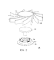
- FIG. 2 is an exploded view illustrating a portion of the power motor depicted in FIG. 1 .
- FIG. 3 is a circuit diagram of the electronic device depicted in FIG. 1 .
- FIG. 4 is a schematic view illustrating an electronic device according to another embodiment of the invention.
- FIG. 1 is a schematic view illustrating an electronic device according to an embodiment of the invention.
- the electronic device 100 of this embodiment includes a power controller 120 and a power motor 130.
- the power controller 120 is used to electrically connect a power storage device 50.
- the electronic device 100 can further include a circuit module 110.
- the circuit module 110 is a computer module, for instance. Nonetheless, the electronic device provided in other embodiments of the invention can also be a tablet PC, a mobile phone, or any other electronic device.
- the power controller 120 can, from the power storage device 50, obtain the electricity required for operating the electronic device 100 and distribute the electricity to each element of the electronic device 100. Note that the electronic device 100 is also likely to use an external power source directly rather than employing the power storage device 50.
- FIG. 2 is an exploded view illustrating a portion of the power motor depicted in FIG. 1 .
- FIG. 3 is a circuit diagram of the electronic device depicted in FIG. 1 .
- the power motor 130 includes a magnetic part 134 and a coil part 136.
- the power motor 130 of this embodiment is exemplarily connected to a fan 132, whereas the power motor 130 in the electronic device 100 can also be applied for other purposes.
- the fan 132 is fixed to the magnetic part 134, whereas the fan 132 described in other embodiments of the invention can be fixed to the coil part.
- the magnetic part 134 is a rotor
- the coil part 136 is a stator.
- the fan 132 fixed to the magnetic part 134 can be rotated together with the magnetic part 134 and generate air.
- the coil part can be the rotor
- the magnetic part can be the stator
- the fan can be fixed to the coil part and rotated together with the magnetic part to generate air.
- the coil part 136 has a main coil C12 and a electromagnetic inducting coil C14 that are electrically connected to the power controller 120. When electricity is supplied to the main coil C12, the magnetic field generated by the main coil C12 interacts with the magnetic field of the magnetic part 134, so as to drive the relative rotation of the magnetic part 134 and the coil part 136. Thereby, the fan 132 is driven to generate airflow and dissipates heat of the circuit module 110.
- the magnetic field of the magnetic part 134 inducted by the electromagnetic inducting coil C 14 of the coil part 136 varies in terms of intensity and direction, and thus the electromagnetic inducting coil C14 generates electricity.
- the power storage device 50 is charged by the electricity (generated by the electromagnetic inducting coil C14) via the power controller 120, which complies with the current trend of reducing power consumption and carbon emissions.
- the power controller 120 includes a rectifier 122 and a power management chip 124.
- the main coil C12 is electrically connected to the power management chip 124.
- the main coil C12 is electrically connected to the power management chip 124 of the power controller 120 via the circuit module 110.
- the electromagnetic inducting coil C14 is electrically connected to the rectifier 122.
- the rectifier 122 is electrically connected to the power management chip 124.
- the electricity generated by the electromagnetic inducting coil C14 is often an alternating current, and the amount of the electricity is inconstant. Accordingly, the rectifier 122 is required for voltage boost and current stabilization. After that, the electricity is supplied to the power management chip 124.
- the power management chip 124 is electrically connected to the power storage device 50.
- the power storage device 50 is a rechargeable battery, for instance.
- the power storage device 50 is a component of the electronic device 100, and the electronic device 100 which is not equipped with the power storage device 50 does not go beyond the scope of the invention.
- the charging procedures of the power storage device 50 in the market are rather complicated. Therefore, by means of the power management chip 124 that can control and monitor the charging procedures, the power storage device 50 can be ideally charged.
- the power management chip 124 manipulates the power charge of the power storage device 50 through a constant current approach in the primary stage of power charge. After an output voltage of the power storage device 50 stably reaches a predetermined value, the power management chip 124 manages to continually charge the power storage device 50 through the constant voltage approach.
- the electronic device 100 of this embodiment can further include a protection circuit 140 that is electrically connected to the power controller 120 and the power motor 130.
- the protection circuit 140 serves to cut off the electrical connection between the power controller 120 and the electromagnetic inducting coil C14 of the power motor 130 before the power controller 120 is overloaded.
- the protection circuit 140 can restrict the amount of electricity output to the power controller 120 from the electromagnetic inducting coil C14 before the power controller 120 is overloaded.
- the protection circuit 140 can assure the voltage value or the current value of the electricity output from the electromagnetic inducting coil C14 to the power controller 120 to be equal to or below a threshold value.
- the protection circuit 140 can protect the power controller 120 which is rather expensive and is likely to affect operation of other components in the electronic device 100. Accordingly, by applying the protection circuit 140, electricity can be prevented from being excessively generated by the power motor 130, and the power controller 120 can be protected from being overloaded and burned out.
- FIG. 4 is a schematic view illustrating an electronic device according to another embodiment of the invention.
- both the power motor 200 in the electronic device of this embodiment and the power motor 130 described in the previous embodiment can generate electricity.
- the difference between the power motor 200 and the power motor 130 lies in that the power motor 200 of this embodiment is not equipped with the fan but with an eccentric 210 fixed to the coil part 220.
- the relative rotation of the magnetic part 230 and the coil part 220 drives the eccentric 210 to rotate and vibrate.
- the eccentric can also be fixed to the magnetic part.
- the power motor in the electronic device of the invention has the electromagnetic inducting coil that can generate electricity inducted by the magnetic field. Therefore, when the power motor is in the required operation, the magnetic field of the magnetic part is simultaneously inducted to generate the electricity. As such, the electricity stored in the power storage device can be increased, and the use time of the electronic device can be extended. Namely, the environmental concern of reducing energy consumption and carbon emissions is taken into account.
- the design of recycling the electricity to extend the use time of the electronic device, as described in the embodiments of the invention, may be of great help to the user of the electronic device at the crucial moment.
Landscapes
- Engineering & Computer Science (AREA)
- Power Engineering (AREA)
- Charge And Discharge Circuits For Batteries Or The Like (AREA)
- Apparatuses For Generation Of Mechanical Vibrations (AREA)
- Secondary Cells (AREA)
- Permanent Magnet Type Synchronous Machine (AREA)
Abstract
An electronic device includes a power controller and a power motor. The power controller is used to electrically connect a power storage device. The power motor includes a magnetic part and a coil part. The coil part has a main coil and a electromagnetic inducting coil that are electrically connected to the power controller. The main coil is used to drive a relative rotation of the magnetic part and the coil part. The electromagnetic inducting coil generates electricity which is inducted by a magnetic field of the magnetic part. The power storage device is charged by the electricity via the power controller.
Description
- The invention relates to an electronic device. More particularly, the invention relates to an electronic device which can be charged by electricity generated by a power motor.
- With continuous advancement of technology, electronic products have been developed towards miniaturization. Common electronic products including tablet PCs, mobile phones, personal digital assistants (PDAs), and notebook computers become indispensable in people's daily lives. In consideration of portability, power required by the portable electronic devices is provided by rechargeable batteries configured in the electronic devices. Hence, the use time of the portable electronic devices is determined based on the power storage capacity of the rechargeable batteries. Given a user stays outdoors for over a long period of time and is thus unable to charge the rechargeable batteries, the exhausted batteries are no longer able to be used, which causes great inconvenience to the user. Accordingly, how to increase the electrical capacity of the electronic device in order to prolong the use of the electronic device becomes an essential topic.
- The invention is directed to an electronic device of which electrical capacity can be increased, such that the use time of the electronic device can be extended.
- The invention provides an electronic device that includes a power controller and a power motor. The power controller is used to electrically connect a power storage device. The power motor includes a magnetic part and a coil part. The coil part has a main coil and a electromagnetic inducting coil that are electrically connected to the power controller. The main coil is used to drive a relative rotation of the magnetic part and the coil part. The electromagnetic inducting coil generates electricity which is inducted by a magnetic field of the magnetic part. The power storage device is charged by the electricity (generated by the electromagnetic inducting coil) via the power controller.
- According to an embodiment of the invention, the electronic device further includes a fan fixed to the magnetic part or the coil part. The relative rotation of the magnetic part and the coil part drives the fan to rotate. In addition, the magnetic part can be a rotor, the coil part can be a stator, and the fan is fixed to the magnetic part.
- According to an embodiment of the invention, the electronic device further includes an eccentric fixed to the magnetic part or the coil part. The relative rotation of the magnetic part and the coil part drives the eccentric to rotate.
- According to an embodiment of the invention, the electronic device further includes a circuit module electrically connected to the power controller. Besides, the main coil can be electrically connected to the power controller via the circuit module.
- According to an embodiment of the invention, the power controller includes a rectifier and a power management chip. The main coil is electrically connected to the power management chip. The electromagnetic inducting coil is electrically connected to the rectifier. The rectifier is electrically connected to the power management chip. The power management chip is electrically connected to the power storage device.
- According to an embodiment of the invention, the electronic device further includes a protection circuit electrically connected to the power controller and the electromagnetic inducting coil for cutting off the electrical connection between the power controller and the electromagnetic inducting coil before the power controller is overloaded or for restricting an amount of the electricity output to the power controller from the electromagnetic inducting coil before the power controller is overloaded.
- According to an embodiment of the invention, the power storage device is a rechargeable battery.
- Based on the above, the power motor of the electronic device has the electromagnetic inducting coil according to the embodiments of the invention. Therefore, when the power motor is operated, the electromagnetic inducting coil can generate electricity inducted by the magnetic field of the magnetic part. The power storage device can be charged by the electricity generated by the electromagnetic inducting coil, so as to extend the use time of the electronic device.
- In order to make the aforementioned and other features and advantages of the invention more comprehensible, embodiments accompanying figures are described in detail below.
- The accompanying drawings constituting a part of this specification are incorporated herein to provide a further understanding of the invention. Here, the drawings illustrate embodiments of the invention and, together with the description, serve to explain the principles of the invention.
-
FIG. 1 is a schematic view illustrating an electronic device according to an embodiment of the invention. -
FIG. 2 is an exploded view illustrating a portion of the power motor depicted inFIG. 1 . -
FIG. 3 is a circuit diagram of the electronic device depicted inFIG. 1 . -
FIG. 4 is a schematic view illustrating an electronic device according to another embodiment of the invention. -
FIG. 1 is a schematic view illustrating an electronic device according to an embodiment of the invention. With reference toFIG. 1 , theelectronic device 100 of this embodiment includes apower controller 120 and apower motor 130. Thepower controller 120 is used to electrically connect apower storage device 50. According to this embodiment, theelectronic device 100 can further include acircuit module 110. When theelectronic device 100 is a notebook computer, thecircuit module 110 is a computer module, for instance. Nonetheless, the electronic device provided in other embodiments of the invention can also be a tablet PC, a mobile phone, or any other electronic device. Thepower controller 120 can, from thepower storage device 50, obtain the electricity required for operating theelectronic device 100 and distribute the electricity to each element of theelectronic device 100. Note that theelectronic device 100 is also likely to use an external power source directly rather than employing thepower storage device 50. -
FIG. 2 is an exploded view illustrating a portion of the power motor depicted inFIG. 1 .FIG. 3 is a circuit diagram of the electronic device depicted inFIG. 1 . With reference toFIG. 2 andFIG. 3 , thepower motor 130 includes amagnetic part 134 and acoil part 136. Thepower motor 130 of this embodiment is exemplarily connected to afan 132, whereas thepower motor 130 in theelectronic device 100 can also be applied for other purposes. In this embodiment, thefan 132 is fixed to themagnetic part 134, whereas thefan 132 described in other embodiments of the invention can be fixed to the coil part. Namely, according to this embodiment, themagnetic part 134 is a rotor, and thecoil part 136 is a stator. Hence, thefan 132 fixed to themagnetic part 134 can be rotated together with themagnetic part 134 and generate air. In other embodiments of the invention, the coil part can be the rotor, the magnetic part can be the stator, and the fan can be fixed to the coil part and rotated together with the magnetic part to generate air. Thecoil part 136 has a main coil C12 and a electromagnetic inducting coil C14 that are electrically connected to thepower controller 120. When electricity is supplied to the main coil C12, the magnetic field generated by the main coil C12 interacts with the magnetic field of themagnetic part 134, so as to drive the relative rotation of themagnetic part 134 and thecoil part 136. Thereby, thefan 132 is driven to generate airflow and dissipates heat of thecircuit module 110. During the relative rotation of themagnetic part 134 and thecoil part 136, the magnetic field of themagnetic part 134 inducted by the electromagnetic inducting coil C 14 of thecoil part 136 varies in terms of intensity and direction, and thus the electromagnetic inducting coil C14 generates electricity. Thepower storage device 50 is charged by the electricity (generated by the electromagnetic inducting coil C14) via thepower controller 120, which complies with the current trend of reducing power consumption and carbon emissions. - In this embodiment, the
power controller 120 includes arectifier 122 and apower management chip 124. The main coil C12 is electrically connected to thepower management chip 124. According to this embodiment, the main coil C12 is electrically connected to thepower management chip 124 of thepower controller 120 via thecircuit module 110. The electromagnetic inducting coil C14 is electrically connected to therectifier 122. Therectifier 122 is electrically connected to thepower management chip 124. The electricity generated by the electromagnetic inducting coil C14 is often an alternating current, and the amount of the electricity is inconstant. Accordingly, therectifier 122 is required for voltage boost and current stabilization. After that, the electricity is supplied to thepower management chip 124. Thepower management chip 124 is electrically connected to thepower storage device 50. Here, thepower storage device 50 is a rechargeable battery, for instance. Note that thepower storage device 50 is a component of theelectronic device 100, and theelectronic device 100 which is not equipped with thepower storage device 50 does not go beyond the scope of the invention. At present, the charging procedures of thepower storage device 50 in the market are rather complicated. Therefore, by means of thepower management chip 124 that can control and monitor the charging procedures, thepower storage device 50 can be ideally charged. For instance, thepower management chip 124 manipulates the power charge of thepower storage device 50 through a constant current approach in the primary stage of power charge. After an output voltage of thepower storage device 50 stably reaches a predetermined value, thepower management chip 124 manages to continually charge thepower storage device 50 through the constant voltage approach. - With reference to
FIG. 1 andFIG. 3 , theelectronic device 100 of this embodiment can further include aprotection circuit 140 that is electrically connected to thepower controller 120 and thepower motor 130. Theprotection circuit 140 serves to cut off the electrical connection between thepower controller 120 and the electromagnetic inducting coil C14 of thepower motor 130 before thepower controller 120 is overloaded. Alternatively, theprotection circuit 140 can restrict the amount of electricity output to thepower controller 120 from the electromagnetic inducting coil C14 before thepower controller 120 is overloaded. For instance, theprotection circuit 140 can assure the voltage value or the current value of the electricity output from the electromagnetic inducting coil C14 to thepower controller 120 to be equal to or below a threshold value. Theprotection circuit 140 can protect thepower controller 120 which is rather expensive and is likely to affect operation of other components in theelectronic device 100. Accordingly, by applying theprotection circuit 140, electricity can be prevented from being excessively generated by thepower motor 130, and thepower controller 120 can be protected from being overloaded and burned out. -
FIG. 4 is a schematic view illustrating an electronic device according to another embodiment of the invention. With reference toFIG. 4 , both thepower motor 200 in the electronic device of this embodiment and thepower motor 130 described in the previous embodiment can generate electricity. The difference between thepower motor 200 and thepower motor 130 lies in that thepower motor 200 of this embodiment is not equipped with the fan but with an eccentric 210 fixed to thecoil part 220. The relative rotation of themagnetic part 230 and thecoil part 220 drives the eccentric 210 to rotate and vibrate. In other embodiments of the invention, the eccentric can also be fixed to the magnetic part. - In light of the foregoing, the power motor in the electronic device of the invention has the electromagnetic inducting coil that can generate electricity inducted by the magnetic field. Therefore, when the power motor is in the required operation, the magnetic field of the magnetic part is simultaneously inducted to generate the electricity. As such, the electricity stored in the power storage device can be increased, and the use time of the electronic device can be extended. Namely, the environmental concern of reducing energy consumption and carbon emissions is taken into account. The design of recycling the electricity to extend the use time of the electronic device, as described in the embodiments of the invention, may be of great help to the user of the electronic device at the crucial moment.
- Although the invention has been described with reference to the above embodiments, it will be apparent to one of the ordinary skill in the art that modifications to the described embodiments may be made without departing from the spirit of the invention. Accordingly, the scope of the invention will be defined by the attached claims rather than by the above detailed descriptions.
Claims (9)
- An electronic device (100) comprising:a power controller (120) for electrically connecting a power storage device (50); anda power motor (130, 200) comprising a magnetic part (134, 230) and a coil part (136, 220), the coil part (136, 220) having a main coil (C12) and a electromagnetic inducting coil (C 14), the main coil (C12) and the electromagnetic inducting coil (C 14) being electrically connected to the power controller (120), the main coil (C12) driving a relative rotation of the magnetic part (134, 230) and the coil part (136, 220), the electromagnetic inducting coil (C14) generating electricity inducted by a magnetic field of the magnetic part (134, 230), wherein the power storage device (50) is charged by the electricity via the power controller (120).
- The electronic device (100) as claimed in claim 1, further comprising a fan (132) fixed to the magnetic part (134) or the coil part (136), wherein the relative rotation of the magnetic part (134) and the coil part (136) drives the fan (132) to rotate.
- The electronic device (100) as claimed in claim 2, wherein the magnetic part (134) is a rotor, the coil part (136) is a stator, and the fan (132) is fixed to the magnetic part (134).
- The electronic device (100) as claimed in claim 1, further comprising an eccentric (210) fixed to the magnetic part (230) or the coil part (220), wherein the relative rotation of the magnetic part (230) and the coil part (220) drives the eccentric (210) to rotate.
- The electronic device (100) as claimed in claim 1, further comprising a circuit module (110) electrically connected to the power controller (120).
- The electronic device (100) as claimed in claim 5, wherein the main coil (C12) is electrically connected to the power controller (120) via the circuit module (110).
- The electronic device (100) as claimed in claim 1, wherein the power controller (120) comprises a rectifier (122) and a power management chip (124), the main coil (C12) is electrically connected to the power management chip (124), the electromagnetic inducting coil (C14) is electrically connected to the rectifier (122), the rectifier (122) is electrically connected to the power management chip (124), and the power management chip (124) is electrically connected to the power storage device (50).
- The electronic device (100) as claimed in claim 1, further comprising a protection circuit (140) electrically connected to the power controller (120) and the electromagnetic inducting coil (C14) for cutting off the electrical connection between the power controller (120) and the electromagnetic inducting coil (C14) before the power controller (120) is overloaded or for restricting an amount of the electricity output to the power controller (120) from the electromagnetic inducting coil (C14) before the power controller (120) is overloaded.
- The electronic device (100) as claimed in claim 1, wherein the power storage device (50) is rechargeable battery.
Applications Claiming Priority (1)
| Application Number | Priority Date | Filing Date | Title |
|---|---|---|---|
| TW100105839A TW201235826A (en) | 2011-02-22 | 2011-02-22 | Electronic device |
Publications (1)
| Publication Number | Publication Date |
|---|---|
| EP2493049A2 true EP2493049A2 (en) | 2012-08-29 |
Family
ID=45715186
Family Applications (1)
| Application Number | Title | Priority Date | Filing Date |
|---|---|---|---|
| EP11160358A Withdrawn EP2493049A2 (en) | 2011-02-22 | 2011-03-30 | Electronic device |
Country Status (8)
| Country | Link |
|---|---|
| US (1) | US20120211994A1 (en) |
| EP (1) | EP2493049A2 (en) |
| JP (1) | JP2012175902A (en) |
| KR (1) | KR20120096384A (en) |
| BR (1) | BRPI1102580A2 (en) |
| DE (1) | DE102011018299A1 (en) |
| RU (1) | RU2011115540A (en) |
| TW (1) | TW201235826A (en) |
Family Cites Families (3)
| Publication number | Priority date | Publication date | Assignee | Title |
|---|---|---|---|---|
| JP2005198366A (en) * | 2003-12-26 | 2005-07-21 | Namiki Precision Jewel Co Ltd | Surface mount type vibration motor and fixing structure of surface mount type vibration motor |
| US8093860B2 (en) * | 2008-12-24 | 2012-01-10 | Tseng Teng-San | Ceiling fan motor with generator winding |
| TW201220637A (en) * | 2010-11-01 | 2012-05-16 | Chung Hsin Elec & Mach Mfg | Charge-controlling system and method therefor |
-
2011
- 2011-02-22 TW TW100105839A patent/TW201235826A/en unknown
- 2011-03-29 US US13/074,009 patent/US20120211994A1/en not_active Abandoned
- 2011-03-30 EP EP11160358A patent/EP2493049A2/en not_active Withdrawn
- 2011-04-20 DE DE102011018299A patent/DE102011018299A1/en not_active Withdrawn
- 2011-04-20 KR KR1020110036858A patent/KR20120096384A/en not_active Ceased
- 2011-04-21 RU RU2011115540/07A patent/RU2011115540A/en not_active Application Discontinuation
- 2011-05-02 BR BRPI1102580-8A patent/BRPI1102580A2/en not_active IP Right Cessation
- 2011-05-20 JP JP2011113726A patent/JP2012175902A/en not_active Abandoned
Non-Patent Citations (1)
| Title |
|---|
| None |
Also Published As
| Publication number | Publication date |
|---|---|
| US20120211994A1 (en) | 2012-08-23 |
| RU2011115540A (en) | 2012-10-27 |
| DE102011018299A1 (en) | 2012-08-23 |
| KR20120096384A (en) | 2012-08-30 |
| JP2012175902A (en) | 2012-09-10 |
| TW201235826A (en) | 2012-09-01 |
| BRPI1102580A2 (en) | 2013-05-28 |
Similar Documents
| Publication | Publication Date | Title |
|---|---|---|
| US7788531B2 (en) | Generation of backing electric current on the basis of a combination of components | |
| US20110241628A1 (en) | Power management unit for portable electronic devices | |
| US20100301808A1 (en) | Charging device and portable electronic device employing the same | |
| US8432130B2 (en) | Wireless rechargeable battery | |
| JP5010692B2 (en) | Information processing apparatus and battery control method | |
| RU2007136916A (en) | DEVICE FOR REVERSE BATTERY CHARGING | |
| CN101043146B (en) | Apparatus and method for managing power of battery packs in a portable device | |
| JP2012009819A (en) | Photovoltaic power generation device | |
| CN101728864A (en) | Charging device | |
| US20110241602A1 (en) | Power supply device | |
| WO2012155461A1 (en) | Mobile terminal and method of providing electrical energy for mobile terminal | |
| CN201063563Y (en) | Portable solar power supply device | |
| CN204992701U (en) | Quick charging device of portable power source | |
| CN102651569A (en) | electronic device | |
| US20100001691A1 (en) | Battery assembly | |
| CN102201681A (en) | Power supply management system of portable computer | |
| CN1592027A (en) | Electronic system and power supply method | |
| EP2493049A2 (en) | Electronic device | |
| CN101841275A (en) | Electronic equipment and power supply management device thereof | |
| KR101750483B1 (en) | Device Having Improved Charging Convenience and Employed with Adaptor | |
| TWM400015U (en) | Power supply device with charging capability and power output system | |
| JP2010148169A (en) | Portable electronic equipment | |
| US20130093379A1 (en) | Electronic device with generator unit | |
| US20090251097A1 (en) | Wind power charging devices | |
| KR20080075766A (en) | Power generator using piezoelectric element |
Legal Events
| Date | Code | Title | Description |
|---|---|---|---|
| PUAI | Public reference made under article 153(3) epc to a published international application that has entered the european phase |
Free format text: ORIGINAL CODE: 0009012 |
|
| 17P | Request for examination filed |
Effective date: 20110330 |
|
| AK | Designated contracting states |
Kind code of ref document: A2 Designated state(s): AL AT BE BG CH CY CZ DE DK EE ES FI FR GB GR HR HU IE IS IT LI LT LU LV MC MK MT NL NO PL PT RO RS SE SI SK SM TR |
|
| AX | Request for extension of the european patent |
Extension state: BA ME |
|
| STAA | Information on the status of an ep patent application or granted ep patent |
Free format text: STATUS: THE APPLICATION HAS BEEN WITHDRAWN |
|
| 18W | Application withdrawn |
Effective date: 20130305 |