EP2492929A2 - Insulating support flange for current loop system - Google Patents
Insulating support flange for current loop system Download PDFInfo
- Publication number
- EP2492929A2 EP2492929A2 EP20120157122 EP12157122A EP2492929A2 EP 2492929 A2 EP2492929 A2 EP 2492929A2 EP 20120157122 EP20120157122 EP 20120157122 EP 12157122 A EP12157122 A EP 12157122A EP 2492929 A2 EP2492929 A2 EP 2492929A2
- Authority
- EP
- European Patent Office
- Prior art keywords
- tubular section
- insulating support
- current loop
- current
- support flange
- Prior art date
- Legal status (The legal status is an assumption and is not a legal conclusion. Google has not performed a legal analysis and makes no representation as to the accuracy of the status listed.)
- Granted
Links
Images


Classifications
-
- H—ELECTRICITY
- H01—ELECTRIC ELEMENTS
- H01F—MAGNETS; INDUCTANCES; TRANSFORMERS; SELECTION OF MATERIALS FOR THEIR MAGNETIC PROPERTIES
- H01F27/00—Details of transformers or inductances, in general
- H01F27/28—Coils; Windings; Conductive connections
- H01F27/32—Insulating of coils, windings, or parts thereof
- H01F27/324—Insulation between coil and core, between different winding sections, around the coil; Other insulation structures
-
- H—ELECTRICITY
- H01—ELECTRIC ELEMENTS
- H01F—MAGNETS; INDUCTANCES; TRANSFORMERS; SELECTION OF MATERIALS FOR THEIR MAGNETIC PROPERTIES
- H01F27/00—Details of transformers or inductances, in general
- H01F27/06—Mounting, supporting or suspending transformers, reactors or choke coils not being of the signal type
-
- H—ELECTRICITY
- H01—ELECTRIC ELEMENTS
- H01F—MAGNETS; INDUCTANCES; TRANSFORMERS; SELECTION OF MATERIALS FOR THEIR MAGNETIC PROPERTIES
- H01F30/00—Fixed transformers not covered by group H01F19/00
- H01F30/04—Fixed transformers not covered by group H01F19/00 having two or more secondary windings, each supplying a separate load, e.g. for radio set power supplies
-
- H—ELECTRICITY
- H01—ELECTRIC ELEMENTS
- H01F—MAGNETS; INDUCTANCES; TRANSFORMERS; SELECTION OF MATERIALS FOR THEIR MAGNETIC PROPERTIES
- H01F38/00—Adaptations of transformers or inductances for specific applications or functions
- H01F38/20—Instruments transformers
- H01F38/22—Instruments transformers for single phase AC
- H01F38/28—Current transformers
-
- H—ELECTRICITY
- H01—ELECTRIC ELEMENTS
- H01F—MAGNETS; INDUCTANCES; TRANSFORMERS; SELECTION OF MATERIALS FOR THEIR MAGNETIC PROPERTIES
- H01F38/00—Adaptations of transformers or inductances for specific applications or functions
- H01F38/20—Instruments transformers
- H01F38/22—Instruments transformers for single phase AC
- H01F38/28—Current transformers
- H01F38/30—Constructions
- H01F2038/305—Constructions with toroidal magnetic core
-
- H—ELECTRICITY
- H03—ELECTRONIC CIRCUITRY
- H03K—PULSE TECHNIQUE
- H03K2217/00—Indexing scheme related to electronic switching or gating, i.e. not by contact-making or -breaking covered by H03K17/00
- H03K2217/0081—Power supply means, e.g. to the switch driver
Definitions
- a motor controller may employ two or more pairs of SCRs for each phase.
- a three phase system with three SCR pairs for each phase may employ 18 SCRs and 18 drivers. Consequently, powering each driver with a dedicated power supply becomes less desirable as the number of switches and drivers increases.
- the central tubular section 60 may also include a lower tubular section 66 having a third inner diameter that is greater than the first and second inner diameters, a third outer diameter that is substantially the same as the first outer diameter (e.g., within 5% of the first outer diameter), and a third thickness that is smaller than the first thickness (e.g., approximately 50% of the first thickness).
- the insulating support flange 44 may also include a rotational locking feature configured to prevent rotation of the insulating support flange 44 relative to other adjacent insulating support flanges 44. More specifically, as described in greater detail below, the rotational locking feature may include a protrusion that extends radially outward from the upper tubular section 64 of the central tubular section 60 near an axial location 86 where the main tubular section 62 transitions into the upper tubular section 64. In addition, the rotational locking feature may also include an indention that extends radially into an inner wall of the lower tubular section 66 near a lower end 88 of the insulating support flange 44.
- FIG. 5 is a top view of the insulating support flange 44 of FIG. 4 .
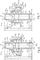
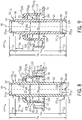
- FIGS. 6-9 are cross-sectional side views of the insulating support flange 44 taken along lines 6-6, 7-7, 8-8, and 9-9 of FIG. 5 , respectively.
- FIGS. 5 through 9 are intended to more fully describe features and dimensions of the insulating support flange 44.
- the outer diameter OD base of the base 74 of the insulating support flange 44 may be approximately 2.9 inches (e.g., within a range of approximately 2.6-3.2 inches). As illustrated in FIG.
- the outer diameter OD US of the upper tubular section 64 will be slightly smaller than the inner diameter ID LS of the lower tubular section 66 such that the upper tubular section 64 of one insulating support flange 44 may fit within the lower tubular section 66 of an adjacent insulating support flange 44 when assembled around the current loop conductor 32.
Landscapes
- Engineering & Computer Science (AREA)
- Power Engineering (AREA)
- Transformers For Measuring Instruments (AREA)
- Inverter Devices (AREA)
Abstract
Description
- The invention relates generally to the field of power control systems. More specifically, the invention relates to an insulating support flange for eliminating partial discharge in a current loop system.
- Motor controllers, and more generally, electrical controllers operate by limiting the power from a power supply that reaches a motor or other load. For example, some motor controllers limit the power delivered to a motor by intermittently conducting current between the power supply and the motor. These motor controllers typically couple to a sinusoidal alternating current (AC) power supply and conduct current during a portion of each cycle of the sinusoid. Correspondingly, to limit the power delivered to the motor, the motor controller may not conduct current during a portion of each cycle. Typically, the duration of the period during which the motor controller does not conduct current is adjustable. Consequently, by adjusting the duration of this non-conductive period, the operation of the motor may be controlled.
- Some motor controllers selectively transmit power by conducting current through a pair of silicon controlled rectifiers (SCRs). An SCR is a type of solid state switch that includes a rectifier controlled by a gate signal. Thus, when turned on by the gate signal, the SCR permits current to flow from its anode to its cathode but not in the reverse direction. Once turned on, the SCR typically remains on until the gate signal is removed and the current decreases to near zero. In the off state, the SCR usually does not conduct current in either direction. By applying a gate signal at the appropriate times, a motor controller may regulate the power delivered to a load.
- Typically, a motor controller includes circuitry for turning on the SCRs. A motor controller may include a driver that delivers a small current to the gate electrode of an SCR. The driver may time the pulse of current to the gate electrode to regulate the power delivered to the motor. To deliver more power, the driver will delay for less time after an SCR becomes forward biased before turning on the SCR. Similarly, to reduce the power delivered to the motor, the driver will delay a longer period after an SCR becomes forward biased before turning on the SCR and permitting current to pass. Each driver includes circuitry for determining when to turn on the SCR. Typically, motor controllers employ one driver for each SCR. Thus, a motor controller regulating a single phase of AC power typically employs two drivers, whereas a three phase controller includes six.
- Powering the operation of the drivers presents challenges. Often, the drivers connect to an SCR that is exposed to high voltages. For example, SCRs often connect to power supplies that operate at 2300 volts or higher. Thus, it may be important to keep the driver electrically isolated from other parts of the system. Some systems employ a single power supply for each driver. However, dedicated power supplies for each driver may add to system costs, the size of the system, and the number of components that may fail. Moreover, motor controllers often employ a large number of drivers. For example, as noted above, a motor controller that regulates power from a three phase AC power supply may employ six drivers, one for each of the two SCRs for each phase. Similarly, to regulate the power from higher voltage power supplies, a motor controller may employ two or more pairs of SCRs for each phase. Thus, a three phase system with three SCR pairs for each phase may employ 18 SCRs and 18 drivers. Consequently, powering each driver with a dedicated power supply becomes less desirable as the number of switches and drivers increases.
- With some success, designers turned to self-powered gate driver systems (SPGDSs) to avoid these issues. Typically, SPGDSs capture energy from the power supply driving the load (i.e., line power). Often, within an SPGDS, a series of capacitors connect to self-powered circuitry that charges the capacitors. The SPGDS may exploit voltage differentials across the SCRs to draw current and store a charge. The charge on the capacitors can then be used to power the drivers. The voltage differentials exploited to charge the capacitors typically occur during the operation of the SCRs. As the SCRs intermittently conduct current between the power source and load, a voltage differential may form across the SCRs. A self-powered system may avoid the isolation issues associated with dedicated power supplies for each driver. Also, the cost of the components directed toward powering the drivers may be lower in a self-powered system than in a system employing dedicated power supplies for each driver. However, SPGDSs are in need of improvement because it is now recognized that SPGDSs are associated with delays in operation and response time.
- The present invention relates generally to systems and methods for isolating a current loop conductor of a current loop system of a pre-charge circuit from a plurality of current transformers disposed around the current loop conductor. In particular, the embodiments described herein include an insulating support flange having a first tubular section, a second tubular section radially disposed around the first tubular section and connected to the first tubular section via a solid annular section extending radially outward from the first tubular section to a first end of the second tubular section, an annular base extending radially outward from a second end of the second tubular section, and a plurality of prongs extending axially from or near to an outer circumference of the annular base, wherein each of the prongs comprises an end face that is angled toward the second tubular section. The insulating support flanges are configured to mate with each other along an axial direction of the current loop conductor. In addition, each of the plurality of current transformers is installed (i.e., held in place) between the prongs, annular base, and second annular section of its respective insulating support flange. As such, a fixed open air space between the first and second annular sections of the insulating support flanges isolates the current transformers from the current loop conductor, thereby reducing the possibility of discharge between the current transformers and the current loop conductor.
- These and other features, aspects, and advantages of the present invention will become better understood when the following detailed description is read with reference to the accompanying drawings in which like characters represent like parts throughout the drawings, wherein:
-
FIG. 1 is a diagrammatical view of an exemplary automation system including an SPGDS that receives a charge from a pre-charge circuit; -
FIG. 2 is a more detailed diagrammatical view of the automation system ofFIG.1 with a circuit diagram of the pre-charge circuit ofFIG. 1 ; -
FIG. 3 is a perspective view of an exemplary current loop system for implementing the pre-charge circuit ofFIGS. 1 and 2 ; -
FIG. 4 is a perspective view of an exemplary insulating support flange of the current loop system ofFIG. 3 ; -
FIG. 5 is a top view of the insulating support flange ofFIG. 4 ; -
FIG. 6 is a cross-sectional side view of the insulating support flange taken along line 6-6 ofFIG. 5 ; -
FIG. 7 is a cross-sectional side view of the insulating support flange taken along line 7-7 ofFIG. 5 ; -
FIG. 8 is a cross-sectional side view of the insulating support flange taken along line 8-8 ofFIG. 5 ; and -
FIG. 9 is a cross-sectional side view of the insulating support flange taken along line 9-9 ofFIG. 5 . - As described above, SPGDSs capture energy from a power supply driving a load using a series of capacitors connected to self-powered circuitry. More specifically, the SPGDSs draw current and store charge through voltage differentials across SCRs. The stored charge may then be used to power drivers of the SPGDS. However, as also described above, SPGDSs are in need of improvement because it is now recognized that SPGDSs are associated with delays in operation and response time. When transitioning from certain modes of operation, the capacitors may lack enough charge to power the drivers. Consequently, a re-activated SPGDS may exhibit a delay before conducting current as the capacitors charge over a few cycles. For example, during full speed operation, some systems bypass the SCRs to deliver power directly from the power supply to the motor. Without a voltage differential across the SCRs, the capacitors may discharge, leaving the drivers without a source of power. Thus, when such a system transitions from full speed operation to a mode where the SPGDS limits the power delivered to the motor, the capacitors powering the driver may lack sufficient charge to restart the driver. The SCRs may remain off for a number of cycles while the capacitors build up a charge sufficient to power the drivers. Similarly, during system startup, the capacitors may have discharged due to a lack of potential across the SCRs. Consequently, during a transition from one of these periods of inactivity, the system may not respond for a few cycles as the capacitors recharge. During this delay, the SCRs may remain off, resulting in an abrupt transition in the power reaching the motor. These sudden transitions may lead to current and torque surges that could contribute to wear on various components within the system.
- Turning now to the drawings,
FIG. 1 depicts anexemplary automation system 10 in accordance with the present techniques. As described in greater detail below, theautomation system 10 may include insulating support flanges for minimizing electrical discharge. Theautomation system 10 ofFIG. 1 may exemplify any number of systems controlling the operation of a load. In one instance, theautomation system 10 may exemplify systems employing alternating current to alternating current (AC-to-AC) motor control, such as automation systems directed toward pumping fluids, operating conveyor belts, air and gas handling, or other forms of factory automation, for example. - The
automation system 10 may include apre-charge circuit 12 to maintain a self-powered gate driver system (SPGDS) 14 in a ready state. During periods of inactivity, when energy stored within theSPGDS 14 might otherwise dissipate, thepre-charge circuit 12 may deliver a small current to keep the SPGDS 14 ready to respond without a charge-up delay when re-activated. Certain embodiments of a singlepre-charge circuit 12 may deliver a current sufficient to maintain an SPGDS 14 with two drivers in a ready state. Indeed, a singlepre-charge circuit 12 may deliver current sufficient to maintainmultiple SPGDSs 14 in a ready state. - One or more SPGDSs 14 may connect to the
pre-charge circuit 12. TheSPGDS 14 may include some energy storage device to receive energy from thepre-charge circuit 12, such as a capacitor, inductor, or battery, for example. Additionally, theSPGDS 14 may include self powered circuitry to capture energy as theSPGDS 14 operates and to charge the energy storage device. For example, the self-powered circuitry may exploit voltage differentials across theSPGDS 14 to charge a capacitor. To control a current passing through theSPGDS 14, it may include a device of variable conductance, such as a thyristor, silicon controlled rectifier, metal oxide semiconductor gated thyristor, thyratron, transistor, gate turn off thyristor, insulated gate bipolar transistor, metal oxide semiconductor field effect transistor, field controlled diodes, junction field effect transistors, static induction transistor, or bipolar junction transistor, for example. - The
SPGDS 14, when active, may control the current between asource 16 and aload 18. Thesource 16 may include various sources of electrical energy, such as an alternating current (AC) or direct current (DC) power supply, for example. In the case of an AC power supply, the current driven by thesource 16 alternates directionally in a sinusoidal manner, as a square wave, as a triangle wave, in an irregular fashion, or in any other form of alternating current. Theload 18 may include any device adapted to harness the current driven by thesource 16. For example, theload 18 may include an electric induction motor, a heating element, an electrochemical process, or an electric arc, for example. TheSPGDS 14 may control the operation of theload 18 by selectively permitting current to flow between thesource 16 and theload 18. - To draw power, the
pre-charge circuit 12 is coupled to acontrol power source 20. Thecontrol power source 20 may be any AC power source with sufficient capacity to enable thepre-charge circuit 12 to energize theSPGDS 14. For example, to reduce costs, thecontrol power source 20 may be a simple line frequency source, such as a 60 Hz, 120 volt AC source as is commonly available in North America or a 50 Hz, 220 volt AC source as is commonly available in Europe. However, controlpower sources 20 operating at other voltages and frequencies may also be employed. Because the demands placed on thecontrol power source 20 by thepre-charge circuit 12 may be much smaller than the demands placed on thesource 16 by theload 18, the root mean square (RMS) voltage supplied by thecontrol power source 20 may be much smaller than the RMS voltage supplied by thesource 16. For example, the RMS voltage of thecontrol power source 20 may be smaller than one half or smaller than one tenth of the RMS voltage of thesource 16. - In operation, the
pre-charge circuit 12 may continuously deliver a small charge to theSPGDS 14, ensuring the components within theSPGDS 14 that power its operation maintain sufficient reserves of stored electrical energy to re-start theSPGDS 14 without delay. When activated, theSPGDS 14 may still draw power from thepre-charge circuit 12, but the self-powered circuitry will draw the bulk of theSPGDS 14 power by exploiting voltage differentials generated as theSPGDS 14 intermittently blocks current flow between thesource 16 and theload 18. However, it should be noted that applications of the present technique are not limited topre-charge circuits 12 which continuously charge theSPGDS 14, as thepre-charge circuit 12 may operate intermittently in some embodiments. When theSPGDS 14 is inactive, the charge provided by thepre-charge circuit 12 may prevent the components powering theSPGDS 14 from becoming de-energized. Thepre-charge circuit 12 may transmit power from thecontrol power source 20 to theSPGDS 14 while keeping theSPGDS 14 electrically isolated. Electrical isolation may be important because theSPGDS 14 may experience voltages from thesource 16 andload 18 that are much larger than the peak voltage of thecontrol power source 20. Thus, thepre-charge circuit 12 may keep the SPGDS 14 isolated. - To illustrate the
pre-charge circuit 12 in more detail,FIG. 2 depicts a circuit diagram of an exemplarypre-charge circuit 12 included within anautomation system 10. To prevent current from flowing between the SPGDS 14 and thecontrol power source 20, thepre-charge circuit 12 may include an insulatedcurrent loop 22 that passes through one or more coils 24. Thecurrent loop 22 may be a wire of sufficient length to extend through thecoils 24. Due to their proximity, an alternating current passed through thecurrent loop 22 induces a current in thecoils 24. This induced current may be harnessed to maintain a charge in theSPGDS 14. As illustrated inFIG. 2 and described in greater detail below, thepre-charge circuit 12 may include one or moreinsulating support flanges 44 configured to minimize discharge between thecurrent loop 22 and thecoils 24. - One or
more bridge rectifiers 26 may rectify alternating currents induced in thecoils 24. Thebridge rectifiers 26 are disposed between the SPGDS 14 and thecoils 24 respectively. Thebridge rectifiers 26 convert an alternating current within thecoils 24 into a unidirectional current that may be employed to charge storage capacitors within theSPGDS 14. Thebridge rectifiers 26 may, for example, include four diodes (e.g., DA1-DA4) in bridge arrangement to achieve full-wafer rectification. However, it should be noted that other embodiments may employ other devices to rectify the current from thecoils 24, such as a half wave rectifier, for example. - In certain embodiments, the
pre-charge circuit 12 may include atransformer 28 to step down the voltage from thecontrol power source 20, as the impedance of thecurrent loop 22 may be very low. Thetransformer 28 may be a simple line transformer adapted to step the voltage from thecontrol power source 20 down to 0.6 volts, for example. However, other embodiments may employtransformers 28 outputting different voltages. By employing acurrent loop 22, the output of asingle transformer 28 may be harnessed to power a plurality of drivers within a plurality ofSPGDSs 14. By addingcoil loops 24 to thepre-charge circuit 12, asingle transformer 28 may support additional SPGDSs 14 and their associated drivers. - The length and gauge of the
current loop 22 may be important to ensure sufficient current is induced in thecoils 24. In some embodiments, thecurrent loop 22 employs between number 4 andnumber 8 gauge wire that is between 10 and 30 feet in length. For example, certain embodiments may employ a 21 foot longcurrent loop 22 ofnumber 6 gauge wire. Acurrent loop 22 of these dimensions coupled to atransformer 28 outputting 0.6 volt alternating current may carry approximately 50 amperes of alternating current within thecurrent loop 22. Thecoils 24 disposed around thiscurrent loop 22 may include an appropriate number of windings to energize the capacitors within theSPGDS 14 during periods of inactivity. -
FIG. 3 is a perspective view of an exemplarycurrent loop system 30 for implementing thepre-charge circuit 12 ofFIGS. 1 and 2 . More specifically, as illustrated inFIG. 3 , thecurrent loop system 30 includes a current loop conductor 32 (e.g., shaped as a long rod inFIG. 3 ), which operates as thecurrent loop 22 of thepre-charge circuit 12 ofFIG. 2 . In addition, thecurrent loop system 30 includes a plurality ofcurrent transformers 34, each having a toroidal magnetic core body disposed around thecurrent loop conductor 32. Thecoils 24 described above with respect toFIG. 2 are wrapped around the toroidal magnetic core body of thecurrent transformers 34. As described above, alternating current flowing axially through thecurrent loop conductor 32, as illustrated byarrow 36, induces a current in thecoils 24 wrapped around the toroidal magnetic core body of thecurrent transformers 34. - The alternating current flowing through the
coils 24 of thecurrent transformers 34 may be used to charge theSPGDS 14 ofFIGS. 1 and 2 during periods of inactivity. More specifically, theSPGDSs 14 described above with respect toFIGS. 1 and 2 include thegate driver boards 38 depicted inFIG. 3 . As illustrated, eachgate driver board 38 is electrically coupled to arespective power brick 40, which are in series and electrically coupled to theload 18 described above with respect toFIGS. 1 and 2 via amain line terminal 42. As such, the alternating current flowing through thecoils 24 of thecurrent transformers 34 may be used to charge thegate driver boards 38 during periods of inactivity. At the same time, current may not flow from thegate driver boards 38, which regulate high voltage power, back to the current loop conductor 32 (i.e., thecurrent loop 22 ofFIG. 2 ), which may operate at much lower voltages. - In certain embodiments, the
current loop conductor 32 may include a conductive core with a layer of insulation having a sufficient thickness and dielectric strength to prevent current from flowing from thecoils 24 to ground. For example, the insulation layer may include a layer of silicon rated at 50 kV of DC power. However, it should be noted that other embodiments may employ other insulators, such as polytetrafluoroethylene, glass braid, ceramic fiber, polyethylene, polypropylene, or any other material with a sufficient dielectric strength. - In addition, the
current loop system 30 includes a plurality of insulatingsupport flanges 44 disposed around thecurrent loop conductor 32 to further isolate thecurrent loop conductor 32 from thecoils 24 of thecurrent transformers 34. In particular, as described in greater detail below, each insulatingsupport flange 44 includes a central tubular body having an open air insulating space between first and second annular sections, and a plurality of prongs extending from a circular base. Thecurrent transformers 34 may be snapped into place between the central tubular body and the plurality of prongs extending from the circular base. In addition, the central tubular bodies of the insulatingsupport flanges 44 are configured to fit within other axially adjacent central tubular bodies, thereby holding the insulatingsupport flanges 44 and associatedcurrent transformers 34 in place and equally spaced axially along thecurrent loop conductor 32. - The insulating
support flanges 44 may be made of a plastic (e.g., an injection molded thermoplastic), or any other electrical grade material having sufficient dielectric strength. In certain embodiments, the insulatingsupport flanges 44 may be corrugated to increase their mechanical strength. The insulatingsupport flanges 44 may protect softer insulators of thecurrent loop conductor 32 from mechanical damage when installing thecurrent loop conductor 32 through thecurrent transformers 34. Additionally, the insulatingsupport flanges 44 may facilitate removal and replacement of thecurrent loop conductor 32. - In addition, as illustrated in
FIG. 3 , thecurrent loop system 30 may include a plurality offlange mounting brackets 46 that may be mounted to (e.g., bolted to) thepower bricks 40. More specifically, theflange mounting brackets 46 may be mounted between alternatingadjacent power bricks 40. In other words, in certain embodiments, theflange mounting brackets 46 may be mounted between every other adjacent pair ofpower bricks 40. However, in other embodiments, the spacing of theflange mounting brackets 46 betweenpower bricks 40 may vary. For example, theflange mounting brackets 46 may be spaced between 1, 3, 4, 5, or more sets ofpower bricks 40. As illustrated, in certain embodiments, theflange mounting brackets 46 may include a generally triangular-shapedplanar body portion 48 having afirst side 50 extending between two powerbrick mounting points 52, and twoother sides 54 extending from the powerbrick mounting points 52 to acommon apex 56. Acircular hole 58 may be cut into theplanar body portion 48 of theflange mounting brackets 46 to enable the insulatingsupport flanges 44 to be mounted within theflange mounting brackets 46. As illustrated inFIG. 3 , in certain embodiments, every third insulatingsupport flange 44 may be mounted to aflange mounting bracket 46. However, in other embodiments, the spacing of the insulatingsupport flanges 44 betweenflange mounting brackets 46 may vary. For example, 2, 4, 5, 6, or moreinsulating support flanges 44 may be supported betweenflange mounting brackets 46. -
FIG. 4 is a perspective view of an exemplary insulatingsupport flange 44 of thecurrent loop system 30 ofFIG. 3 . As illustrated, the insulatingsupport flange 44 may include acentral tubular section 60, which is an annular section within which thecurrent loop conductor 32 may be installed. Thecentral tubular section 60 may include a maintubular section 62 having a first inner diameter, a first outer diameter, and a first thickness. Thecentral tubular section 60 may also include anupper tubular section 64 having a second inner diameter that is substantially the same as the first inner diameter (e.g., within 5% of the first inner diameter), a second outer diameter that is smaller than the first outer diameter, and a second thickness that is smaller than the first thickness (e.g., approximately 50% of the first thickness). Thecentral tubular section 60 may also include a lowertubular section 66 having a third inner diameter that is greater than the first and second inner diameters, a third outer diameter that is substantially the same as the first outer diameter (e.g., within 5% of the first outer diameter), and a third thickness that is smaller than the first thickness (e.g., approximately 50% of the first thickness). - In general, the
upper tubular section 64 of one insulatingsupport flange 44 is configured to fit securely within the lowertubular section 66 of another adjacent insulatingsupport flange 44, More specifically, the second outer diameter of theupper tubular section 64 is substantially the same as (or slightly smaller than) the third inner diameter of the lowertubular section 66. In general, the maintubular section 62 is substantially longer than both the upper and lowertubular sections tubular section 62 may be between approximately 3-8 times longer than both the upper and lowertubular sections - As also illustrated in
FIG. 4 , the insulatingsupport flange 44 includes a second annular section 68 (i.e., with thecentral tubular section 60 being the first annular section) that is radially disposed around thecentral tubular section 60. In particular, as described in greater detail below, the annular section 68 includes a generallyplanar section 70 that forms an annular plane extending radially from thecentral tubular section 60, and an outertubular section 72 that extends axially from the outer edges of the generally planar section 70 (e.g., concentric to the central tubular section 60). As such, as described in greater detail below, thecentral tubular section 60 and the annular section 68 form a fixed open space therebetween, which further insulates thecurrent loop conductor 32 from thecurrent transformers 34 during operation. - The insulating
support flange 44 also includes a generallyplanar base 74 that forms an annular plane extending radially from anend 76 of the outertubular section 72. In addition, the insulatingsupport flange 44 includes a plurality ofprongs 78. In certain embodiments, theprongs 78 extend from the base 74 at or near an outer circumference 80 of thebase 74. However, in other embodiments, the plurality ofprongs 78 may be located at other (e.g., inner) radial locations of thebase 74. The embodiments described herein include threeprongs 78 extending from thebase 74 and substantially equally spaced circumferentially around thebase 74. However, in other embodiments, 2, 4, 5, or evenmore prongs 78 may be used. In general, thesupport flange 44 is configured to couple with one of thecurrent transformers 34, such that thecurrent transformer 34 snaps into place between theprongs 78, thebase 74, and the outertubular section 72 with theprongs 78 holding thecurrent transformers 34 in place. More specifically, each of theprongs 78 includes anend 82 that extends radially inward toward the outertubular section 72 such that atransformer 34 may be held in place between theprongs 78, thebase 74, and the outertubular section 72. In addition, theend 82 includes anangled end face 84 that enables acurrent transformer 34 to be moved into place, with theprongs 78 giving way slightly in the radial direction. - Although not illustrated in the perspective view of
FIG. 4 , in certain embodiments, the insulatingsupport flange 44 may also include a rotational locking feature configured to prevent rotation of the insulatingsupport flange 44 relative to other adjacent insulatingsupport flanges 44. More specifically, as described in greater detail below, the rotational locking feature may include a protrusion that extends radially outward from theupper tubular section 64 of thecentral tubular section 60 near anaxial location 86 where the maintubular section 62 transitions into theupper tubular section 64. In addition, the rotational locking feature may also include an indention that extends radially into an inner wall of the lowertubular section 66 near alower end 88 of the insulatingsupport flange 44. As described in greater detail below, when adjacent insulatingsupport flanges 44 are axially installed next to each other around thecurrent loop conductor 32, the protrusion extending radially outward from theupper tubular section 64 of one insulatingsupport flange 44 aligns and mates with the indention extending radially into the inner wall of the lowertubular section 66 of the adjacent insulatingsupport flange 44. As such, rotation of the adjacent insulatingsupport flanges 44 is substantially prevented. - In addition, in certain embodiments, the insulating
support flange 44 may include acutout section 90 near the outer circumference 80 of thebase 74, which facilitates traversal of wiring (e.g., the coils 24) from thecurrent transformer 34 that is mounted on the insulatingsupport flange 44. In addition, in certain embodiments, the insulatingsupport flange 44 may include one ormore holes 92 through the base 74 adjacent the outertubular section 72, and associatedgrooves 94 in the outertubular section 72 adjacent thebase 74. Theholes 92 andgrooves 94 facilitate the mounting of the insulatingsupport flanges 44 to theflange mounting brackets 46 illustrated inFIG. 3 . More specifically, bolts (not shown) may be passed through the holes 92 (with thegrooves 94 providing room for the bolts if needed) such that the bolts secure the insulatingsupport flange 44 to aflange mounting bracket 46. -
FIG. 5 is a top view of the insulatingsupport flange 44 ofFIG. 4 . In addition,FIGS. 6-9 are cross-sectional side views of the insulatingsupport flange 44 taken along lines 6-6, 7-7, 8-8, and 9-9 ofFIG. 5 , respectively.FIGS. 5 through 9 are intended to more fully describe features and dimensions of the insulatingsupport flange 44. For example, in certain embodiments, the outer diameter ODbase of thebase 74 of the insulatingsupport flange 44 may be approximately 2.9 inches (e.g., within a range of approximately 2.6-3.2 inches). As illustrated inFIG. 5 , in certain embodiments, the insulatingsupport flange 44 may include threeprongs 78 that are equally spaced (i.e., 120 degrees apart) around the circumference 80 of thebase 74. However, as described above, the insulatingsupport flange 44 may instead have 2, 4, 5, or evenmore prongs 78 spaced around the circumference 80 of thebase 74. In addition, in certain embodiments, theprongs 78 may not be equally spaced around the circumference 80 of thebase 74. - As also illustrated in
FIG. 5 , in certain embodiments, the insulatingsupport flange 44 may have the twoholes 92 disposed on opposite sides of the outertubular section 72 in thebase 74. However, the insulatingsupport flange 44 may instead include more than twoholes 92. As described above, theholes 92 facilitate mounting of the insulatingsupport flange 44 to aflange mounting bracket 46. As also illustrated inFIG. 5 , in certain embodiments, thebase 74 of the insulatingsupport flange 44 may include thecutout section 90, which as described above facilitates traversal of wiring (e.g., the coils 24) from thecurrent transformer 34 that is mounted on the insulatingsupport flange 44. As illustrated, in certain embodiments, thecutout section 90 may be generally rectangular shaped, with aninner side 96 being spaced at a distance dCO approximately 1.05 inches (e.g., within a range of approximately 0.95-1.15 inches) from acentral axis 98 of the insulatingsupport flange 44. In addition, in certain embodiments, theinner side 96 of the generally rectangular shapedcutout section 90 may have a width wCO of approximately 1 inch (e.g., within a range of approximately 0.9-1.1 inches). -
FIG. 5 also illustrates aprotrusion 100 that extends radially outward from theupper tubular section 64 of thecentral tubular section 60 near theaxial location 86 where the maintubular section 62 transitions into theupper tubular section 64.FIG. 6 also illustrates theprotrusion 100, as well as anindention 102 that extends radially into theinner wall 104 of the lowertubular section 66 near thelower end 88 of the insulatingsupport flange 44. As described above, theprotrusion 100 and theindention 102 together form a rotational locking feature that substantially prevents rotation of adjacent insulatingsupport flanges 44. More specifically, when adjacent insulatingsupport flanges 44 are axially installed next to each other around thecurrent loop conductor 32, theprotrusion 100 of one insulatingsupport flange 44 aligns and mates with theindention 102 of an adjacent insulatingsupport flange 44. As illustrated inFIG. 6 , in certain embodiments, both the length lPRO of theprotrusion 100 and the length lIND of theindention 102 may be approximately 0.12 inches (e.g., within a range of approximately 0.1-0.14). Regardless of the exact dimensions, the length lIND of theindention 102 may be slightly greater than the length lPRO of theprotrusion 100 such that theprotrusion 100 of one insulatingsupport flange 44 fits within theindention 102 of an adjacent insulatingsupport flange 44 when adjacent insulatingsupport flanges 44 are axially installed next to each other around thecurrent loop conductor 32. - As also illustrated in
FIGS. 6 through 9 , in certain embodiments, the inner diameter IDUS of theupper tubular section 64 and the inner diameter IDMS of the maintubular section 62 may both be approximately 0.63 inches (e.g., within a range of approximately 0.56-0.7 inches), and the inner diameter IDLS of the lowertubular section 66 may be approximately 0.81 inches (e.g., within a range of approximately 0.72-0.9 inches). In addition, in certain embodiments, the outer diameter ODUS of theupper tubular section 64 may be approximately 0.8 inches (e.g., within a range of approximately 0.72-0.9 inches), and the outer diameter ODMS of the maintubular section 62 and the outer diameter ODLS of the lowertubular section 66 may both be approximately 0.9 inches (e.g., within a range of approximately 0.8-1.0 inches). Regardless of the exact dimensions, as described above, the outer diameter ODUS of theupper tubular section 64 will be slightly smaller than the inner diameter IDLS of the lowertubular section 66 such that theupper tubular section 64 of one insulatingsupport flange 44 may fit within the lowertubular section 66 of an adjacent insulatingsupport flange 44 when assembled around thecurrent loop conductor 32. - As also illustrated in
FIGS. 6 through 9 , in certain embodiments, the length lUS of the upperannular section 64 of the centralannular section 60 may be approximately 0.4 inches (e.g., within a range of approximately 0.35-0.45), the length lMS of the mainannular section 62 of the centralannular section 60 may be approximately 3 inches (e.g., within a range of approximately 2.7-3.3), and the length lLS of the lowerannular section 66 of the centralannular section 60 may be approximately 0.4 inches (e.g., within a range of approximately 0.35-0.45). As such, the total length lCS of the centralannular section 60 may be approximately 3.8 inches (e.g., within a range of approximately 3.4-4.2 inches). In addition, the generallyplanar section 70 extending from the maintubular section 62 and connecting to the outertubular section 72 may be axially located along the maintubular section 62 by a distance dPS of approximately 0.5 inches (e.g., within a range of approximately 0.45-0.55 inches) from theaxial location 86 where the maintubular section 62 transitions into theupper tubular section 64. - As also illustrated in
FIGS. 6 through 9 , in certain embodiments, the outer diameter ODOTS of the outertubular section 72 may be approximately 1.77 inches (e.g., within a range of approximately 1.6-1.95 inches), and the inner diameter IDOTS of the outertubular section 72 may be approximately 1.5 inches (e.g., within a range of approximately 1.35-1.65 inches). As such, the inner diameter IDOTS of the outertubular section 72 may be substantially larger than the outer diameter ODMS of the maintubular section 62, thereby forming a fixed, open air space 106 (i.e., an annular open air volume) between the maintubular section 62 and the outertubular section 72. For example, assuming that the outer diameter ODMS of the maintubular section 62 is approximately 0.9 inches and the inner diameter IDOTS of the outertubular section 72 is approximately 1.5 inches, anouter wall 108 of the maintubular section 62 and aninner wall 110 of the outertubular section 72 are separated by an open air space distance dOAS of approximately 0.3 inches. As such, in certain embodiments, the open air space distance dOAS may be greater than approximately 25% of the outer diameter ODMS of the maintubular section 62. - As also illustrated in
FIG. 7 , in certain embodiments, each of theprongs 78 may have a length lprong of approximately 0.6 inches (e.g., within a range of approximately 0.54-0.66 inches), with theend 82 having a width wend of approximately 0.09 inches (e.g., within a range of approximately 0.08-0.1 inches). In addition, in certain embodiments, theprongs 78 may have a width wprong of approximately 0.11 inches (e.g., within a range of approximately 0.1-0.12 inches). In addition, in certain embodiments, thebase 74 may have a width wbase of approximately 0.15 inches (e.g., within a range of approximately 0.13-0.17 inches). - As described above, the insulating
support flanges 44 enable isolation of thecurrent loop conductor 32 from thecurrent transformers 34 ofFIG. 3 . When using higher power system voltages (e.g., up to, or even greater than, 15 kV), insulation integrity becomes more and more important. Conventional techniques have exhibited high levels of partial discharge and low inception voltages, resulting in eventual product performance degradation, with the potential for internal arc faults. The insulatingsupport flanges 44 described herein ensure that no solid media or trapped air pockets are in contact with either thecurrent loop conductor 32 or thecurrent transformers 34. More specifically, the fixed, open layer of air insulation (i.e., the fixed,open air space 106 between the maintubular section 62 and the outer tubular section 72) eliminates partial discharge issues present in conventional systems. In addition, the insulatingsupport flanges 44 are designed as interlocking molded profiles, such that the insulatingsupport flanges 44 are highly modular in nature, enhancing reusability and replaceability. As such, the embodiments described herein provide a robust, reliable, scalable, and cost effective alternative to conventional techniques. - While only certain features of the invention have been illustrated and described herein, many modifications and changes will occur to those skilled in the art. It is, therefore, to be understood that the appended claims are intended to cover all such modifications and changes as fall within the true spirit of the invention.
-
- Embodiment 1: An insulating support flange, comprising:
- a first tubular section;
- a second tubular section radially disposed around the first tubular section and connected to the first tubular section via a solid annular section extending radially outward from the first tubular section to a first end of the second tubular section, wherein an annular open air volume is formed between an inner wall of the second tubular section and an outer wall of the first tubular section;
- an annular base extending radially outward from a second end of the second tubular section; and
- a plurality of prongs extending axially from the annular base proximate a circumference of the annular base.
- Embodiment 2: The insulating support flange of
embodiment 1, wherein a distance between the inner wall of the second tubular section and the outer wall of the first tubular section is greater than approximately 25% of an outer diameter of the first tubular section. - Embodiment 3: The insulating support flange of
embodiment 1, wherein the first tubular section comprises a main tubular section having a first inner diameter and a first outer diameter, an upper tubular section extending axially from a first end of the main tubular section and having a second inner diameter and a second outer diameter, and a lower tubular section extending axially from a second end of the main tubular section and having a third inner diameter and a third outer diameter, wherein the second outer diameter is slightly smaller than the third inner diameter. - Embodiment 4: The insulating support flange of embodiment 3, wherein the first inner diameter and the second inner diameter are substantially similar in size, and the first outer diameter and the third outer diameter are substantially similar in size.
- Embodiment 5: The insulating support flange of embodiment 3, wherein the upper tubular section comprises a protrusion extending radially outward adjacent an axial location where the main tubular section and the upper tubular section abut.
- Embodiment 6: The insulating support flange of
embodiment 5, wherein the lower tubular section comprises an indention in an inner wall of the lower tubular section at an end of the first tubular section. - Embodiment 7: The insulating support flange of
embodiment 1, wherein the annular base comprises one or more holes adjacent the second tubular section. - Embodiment 8: The insulating support flange of
embodiment 1, wherein the annular base comprises a cutout portion near the outer circumference of the annular base. - Embodiment 9: The insulating support flange of
embodiment 1, wherein each of the plurality of prongs comprises an end that extends radially toward the second tubular section. - Embodiment 10: The insulating support flange of
embodiment 1, wherein the plurality of prongs are substantially equally spaced around the outer circumference of the annular base. - Embodiment 11: A current loop system, comprising:
- a current loop conductor rod;
- a plurality of insulating support flanges disposed radially around the current loop conductor rod, wherein tubular sections of adjacent insulating support flanges mate in an axial direction along the current loop conductor rod; and
- a plurality of annular current transformers, each current transformer installed in a respective insulating support flange such that the current transformer is disposed radially around the current loop conductor rod but isolated from the current loop conductor rod by its respective insulating support flange.
- Embodiment 12: The current loop system of embodiment 11, wherein each insulating support flange comprises:
- a first tubular section configured to mate with first tubular sections of adjacent insulating support flanges in the axial direction along the current loop conductor rod;
- a second tubular section radially disposed around the first tubular section and connected to the first tubular section via a solid annular section extending radially outward from the first tubular section to a first end of the second tubular section, wherein an annular open air volume s formed between an inner wall of the second tubular section and an outer wall of the first tubular section;
- an annular base extending radially outward from a second end of the second tubular section; and
- a plurality of prongs extending axially from the annular base proximate a circumference of the annular base, wherein the respective current transformer is held in place between the plurality of prongs, the annular base, and the second tubular section.
- Embodiment 13: The current loop system of
embodiment 12, wherein the first tubular section comprises a main tubular section having a first inner diameter and a first outer diameter, an upper tubular section extending axially from a first end of the main tubular section and having a second inner diameter and a second outer diameter, and a lower tubular section extending axially from a second end of the main tubular section and having a third inner diameter and a third outer diameter, wherein the second outer diameter is slightly smaller than the third inner diameter, and wherein the upper tubular sections and lower tubular sections of adjacent insulating support flanges mate in the axial direction along the current loop conductor rod. - Embodiment 14: The current loop system of embodiment 13, wherein the first inner diameter and the second inner diameter are substantially similar in size, and the first outer diameter and the third outer diameter are substantially similar in size.
- Embodiment 15: The current loop system of embodiment 13, wherein the upper tubular section comprises a protrusion extending radially outward adjacent an axial location where the main tubular section and the upper tubular section abut.
- Embodiment 16: The current loop system of embodiment 15, wherein the lower tubular section comprises an indention in an inner wall of the lower tubular section at an end of first tubular section, and wherein the protrusions of the upper tubular sections and the indentions of the lower tubular sections of adjacent insulating support flanges mate.
- Embodiment 17: The current loop system of
embodiment 12, wherein the annular base comprises one or more holes adjacent the second tubular section. - Embodiment 18: The current loop system of
embodiment 12, wherein each of the plurality of prongs comprises an end that extends radially toward the second tubular section. - Embodiment 19: A system, comprising:
- a plurality of power sources arranged in series and terminating with a main line terminal;
- a plurality of gate driver boards, each comprising self-powered gate circuitry configured to control current from the plurality of power sources to a load via the main line terminal; and
- a current loop system configured to provide power from a control power source to the plurality of gate driver boards, the current loop system comprising:
- a current loop conductor rod configured to flow a first current from the control power source;
- a plurality of insulating support flanges disposed radially around the current loop conductor rod, wherein tubular sections of adjacent insulating support flanges mate in an axial direction along the current loop conductor rod; and
- a plurality of annular current transformers, each current transformer installed in a respective insulating support flange such that the current transformer is disposed radially around the current loop conductor rod but isolated from the current loop conductor rod by its respective insulating support flange, wherein the first current flowing through the current loop conductor rod generates a second current through windings of the current transformers, and wherein the second current flowing through the current transformers provides power to the gate driver boards.
- Embodiment 20: The system of embodiment 19, wherein each insulating support flange comprises:
- a first tubular section configured to mate with first tubular sections of adjacent insulating support flanges in the axial direction along the current loop conductor rod;
- a second tubular section radially disposed around the first tubular section and connected to the first tubular section via a solid annular section extending radially outward from the first tubular section to a first end of the second tubular section, wherein an annular open air volume is formed between an inner wall of the second tubular section and an outer wall of the first tubular section;
- an annular base extending radially outward from a second end of the second tubular section; and
- a plurality of prongs extending axially from the annular base proximate a circumference of the annular base, wherein the respective current transformer is held in place between the plurality of prongs, the annular base, and the second tubular section.
Claims (15)
- An insulating support flange, comprising:a first tubular section;a second tubular section radially disposed around the first tubular section and connected to the first tubular section via a solid annular section extending radially outward from the first tubular section to a first end of the second tubular section, wherein an annular open air volume is formed between an inner wall of the second tubular section and an outer wall of the first tubular section;an annular base extending radially outward from a second end of the second tubular section; anda plurality of prongs extending axially from the annular base proximate a circumference of the annular base.
- The insulating support flange of claim 1, wherein a distance between the inner wall of the second tubular section and the outer wall of the first tubular section is greater than approximately 25% of an outer diameter of the first tubular section.
- The insulating support flange of claim 1, wherein the first tubular section comprises a main tubular section having a first inner diameter and a first outer diameter, an upper tubular section extending axially from a first end of the main tubular section and having a second inner diameter and a second outer diameter, and a lower tubular section extending axially from a second end of the main tubular section and having a third inner diameter and a third outer diameter, wherein the second outer diameter is slightly smaller than the third inner diameter.
- The insulating support flange of claim 3, wherein the first inner diameter and the second er diameter are substantially similar in size, and the first outer diameter and the third outer diameter are substantially similar in size.
- The insulating support flange of claim 3, wherein the upper tubular section comprises a protrusion extending radially outward adjacent an axial location where the main tubular section and the upper tubular section abut, and
wherein the lower tubular section comprises an indention in an inner wall of the lower tubular section at an end of the first tubular section. - The insulating support flange of claim 1, wherein the annular base comprises one or more holes adjacent the second tubular section, or
wherein the annular base comprises a cutout portion near the outer circumference of the annular base. - The insulating support flange of claim 1, wherein each of the plurality of prongs comprises an end that extends radially toward the second tubular section, and/or
wherein the plurality of prongs are substantially equally spaced around the outer circumference of the annular base. - A current loop system, comprising:a current loop conductor rod;a plurality of insulating support flanges disposed radially around the current loop conductor rod, wherein tubular sections of adjacent insulating support flanges mate in an axial direction along the current loop conductor rod; anda plurality of annular current transformers, each current transformer installed in a respective insulating support flange such that the current transformer is disposed radially around the current loop conductor rod but isolated from the current loop conductor rod by its respective insulating support flange.
- The current loop system of claim 8, wherein each insulating support flange comprises:a first tubular section configured to mate with first tubular sections of adjacent insulating support flanges in the axial direction along the current loop conductor rod;a second tubular section radially disposed around the first tubular section and connected to the first tubular section via a solid annular section extending radially outward from the first tubular section to a first end of the second tubular section, wherein an annular open air volume is formed between an inner wall of the second tubular section and an outer wall of the first tubular section;an annular base extending radially outward from a second end of the second tubular section; anda plurality of prongs extending axially from the annular base proximate a circumference of the annular base, wherein the respective current transformer is held in place between the plurality of prongs, the annular base, and the second tubular section.
- The current loop system of claim 9, wherein the first tubular section comprises a main tubular section having a first inner diameter and a first outer diameter, an upper tubular section extending axially from a first end of the main tubular section and having a second inner diameter and a second outer diameter, and a lower tubular section extending axially from a second end of the main tubular section and having a third inner diameter and a third outer diameter, wherein the second outer diameter is slightly smaller than the third inner diameter, and wherein the upper tubular sections and lower tubular sections of adjacent insulating support flanges mate in the axial direction along the current loop conductor rod.
- The current loop system of claim 10, wherein the first inner diameter and the second inner diameter are substantially similar in size, and the first outer diameter and the third outer diameter are substantially similar in size.
- The current loop system of claim 10, wherein the upper tubular section comprises a protrusion extending radially outward adjacent an axial location where the main tubular section and the upper tubular section abut, and
wherein the lower tubular section comprises an indention in an inner wall of the lower tubular section at an end of first tubular section, and wherein the protrusions of the upper tubular sections and the indentions of the lower tubular sections of adjacent insulating support flanges mate. - The current loop system of claim 9, wherein the annular base comprises one or more holes adjacent the second tubular section, and/or
wherein each of the plurality of prongs comprises an end that extends radially toward the second tubular section. - A system, comprising:a plurality of power sources arranged in series and terminating with a main line terminal;a plurality of gate driver boards, each comprising self-powered gate circuitry configured to control current from the plurality of power sources to a load via the main line terminal; anda current loop system configured to provide power from a control power source to the plurality of gate driver boards, the current loop system comprising:a current loop conductor rod configured to flow a first current from the control power source;a plurality of insulating support flanges disposed radially around the current loop conductor rod, wherein tubular sections of adjacent insulating support flanges mate in an axial direction along the current loop conductor rod; anda plurality of annular current transformers, each current transformer installed in a respective insulating support flange such that the current transformer is disposed radially around the current loop conductor rod but isolated from the current loop conductor rod by its respective insulating support flange, wherein the first current flowing through the current loop conductor rod generates a second current through windings of the current transformers, and wherein the second current flowing through the current transformers provides power to the gate driver boards.
- The system of claim 14, wherein each insulating support flange comprises:a first tubular section configured to mate with first tubular sections of adjacent insulating support flanges in the axial direction along the current loop conductor rod;a second tubular section radially disposed around the first tubular section and connected to the first tubular section via a solid annular section extending radially outward from the first tubular section to a first end of the second tubular section, wherein an annular open air volume is formed between an inner wall of the second tubular section and an outer wall of the first tubular section;an annular base extending radially outward from a second end of the second tubular section; anda plurality of prongs extending axially from the annular base proximate a circumference of the annular base, wherein the respective current transformer is held in place between the plurality of prongs, the annular base, and the second tubular section.
Applications Claiming Priority (1)
| Application Number | Priority Date | Filing Date | Title |
|---|---|---|---|
| US13/035,560 US8952275B2 (en) | 2011-02-25 | 2011-02-25 | Insulating support flange for current loop system |
Publications (3)
| Publication Number | Publication Date |
|---|---|
| EP2492929A2 true EP2492929A2 (en) | 2012-08-29 |
| EP2492929A3 EP2492929A3 (en) | 2017-12-20 |
| EP2492929B1 EP2492929B1 (en) | 2019-01-16 |
Family
ID=45774025
Family Applications (1)
| Application Number | Title | Priority Date | Filing Date |
|---|---|---|---|
| EP12157122.8A Active EP2492929B1 (en) | 2011-02-25 | 2012-02-27 | Insulating support flange for current loop system |
Country Status (3)
| Country | Link |
|---|---|
| US (2) | US8952275B2 (en) |
| EP (1) | EP2492929B1 (en) |
| CN (1) | CN102682935B (en) |
Families Citing this family (1)
| Publication number | Priority date | Publication date | Assignee | Title |
|---|---|---|---|---|
| CN112117045A (en) * | 2020-09-21 | 2020-12-22 | 昆明昆宝电线电缆制造有限公司 | High-temperature-resistant silicon rubber control cable |
Family Cites Families (17)
| Publication number | Priority date | Publication date | Assignee | Title |
|---|---|---|---|---|
| US3793562A (en) * | 1973-03-22 | 1974-02-19 | Westinghouse Electric Corp | With insulating battle supporting terminal conductors |
| US4202998A (en) * | 1978-07-17 | 1980-05-13 | Gould Inc. | Air entrance bushing for gas-insulated bus |
| DE4337403A1 (en) * | 1993-10-26 | 1995-04-27 | Siemens Ag | Electrical high-voltage switchgear with a toroidal current transformer |
| US5796599A (en) | 1997-03-12 | 1998-08-18 | Reliance Electric Industrial Company | Self-powered gate driver board |
| JPH10271643A (en) * | 1997-03-21 | 1998-10-09 | Yazaki Corp | Still water grommet |
| JP3940229B2 (en) * | 1998-09-30 | 2007-07-04 | 矢崎総業株式会社 | Harness grommet |
| EP1182091B1 (en) * | 2000-01-11 | 2007-05-30 | Yazaki Corporation | Grommet |
| JP3757106B2 (en) * | 2000-10-27 | 2006-03-22 | 矢崎総業株式会社 | Grommet |
| JP4091277B2 (en) * | 2001-07-18 | 2008-05-28 | 矢崎総業株式会社 | Grommet |
| JP3947801B2 (en) * | 2001-11-27 | 2007-07-25 | 株式会社日立製作所 | Current transformer fixing device |
| US6951987B1 (en) * | 2003-01-31 | 2005-10-04 | United States Of America As Represented By The Secretary Of The Navy | High voltage bushing |
| CN2777725Y (en) * | 2004-11-17 | 2006-05-03 | 郭志忠 | Optical current transformer isolator |
| US7576451B2 (en) | 2005-09-28 | 2009-08-18 | Rockwell Automation Technologies, Inc. | Self powered gate driver system |
| US7415891B2 (en) * | 2005-09-30 | 2008-08-26 | Rockwell Automation Technologies, Inc. | Sensor mounting structure with snapping feature |
| DE102005059754B4 (en) * | 2005-12-09 | 2010-05-27 | Siemens Ag | Injection molded outer cone bushing |
| US7544130B2 (en) * | 2006-09-13 | 2009-06-09 | Reliance Electric Technologies, Llc | Flexible shaft coupling system with antirotational features |
| CN101145677B (en) * | 2007-08-06 | 2010-05-19 | 云南开关厂 | Special gas insulation combined appliance for electric railroad |
-
2011
- 2011-02-25 US US13/035,560 patent/US8952275B2/en active Active
-
2012
- 2012-02-27 CN CN201210046951.3A patent/CN102682935B/en not_active Expired - Fee Related
- 2012-02-27 EP EP12157122.8A patent/EP2492929B1/en active Active
-
2015
- 2015-01-06 US US14/590,696 patent/US9576723B2/en active Active
Non-Patent Citations (1)
| Title |
|---|
| None |
Also Published As
| Publication number | Publication date |
|---|---|
| US20120218070A1 (en) | 2012-08-30 |
| CN102682935B (en) | 2015-07-22 |
| US8952275B2 (en) | 2015-02-10 |
| US20150116066A1 (en) | 2015-04-30 |
| CN102682935A (en) | 2012-09-19 |
| US9576723B2 (en) | 2017-02-21 |
| EP2492929B1 (en) | 2019-01-16 |
| EP2492929A3 (en) | 2017-12-20 |
Similar Documents
| Publication | Publication Date | Title |
|---|---|---|
| US10348186B2 (en) | Overvoltage limiting of AC voltage generation | |
| US11824374B2 (en) | Variable wireless power transfer system | |
| CN104221268B (en) | Method and apparatus for transferring power by capacitive coupling | |
| EP2445083B1 (en) | Contactless power-feed equipment | |
| CN103999312B (en) | Input/output power and signal transfer isolator device | |
| JP5860581B2 (en) | System and method for providing a power converter | |
| US20130010507A1 (en) | Protected power conversion device and control method | |
| US7576451B2 (en) | Self powered gate driver system | |
| JP6271175B2 (en) | AC / DC converter and its control circuit, power adapter and electronic device | |
| JP6035282B2 (en) | Inductive power transmission device | |
| KR20190043268A (en) | Dc-dc converter | |
| CN103959629B (en) | For the multiplier rectifier of multiphase non-contact type energy transmission system | |
| JP2016521103A (en) | Electrical energy storage and power management system | |
| US9576723B2 (en) | Insulating support flange for current loop system | |
| CN107000600A (en) | Device for charging and running load unit to battery unit by inverter | |
| US11201552B2 (en) | Power supply system and DC/DC converter | |
| JP5349698B2 (en) | Auxiliary power supply for vehicle | |
| CN108336942A (en) | Three phase electric machine driving circuit | |
| US20250118968A1 (en) | Electrical Power System | |
| US20230028138A1 (en) | Motor | |
| CN113767548A (en) | Wireless power transmission system | |
| KR101344121B1 (en) | Apparatus and method for controlling field current of super conducting elecreic power generator | |
| KR101654143B1 (en) | The output voltage control system of three-phase induction generator using the self excitation capacitance controller | |
| JPH10106856A (en) | DC power supply |
Legal Events
| Date | Code | Title | Description |
|---|---|---|---|
| PUAI | Public reference made under article 153(3) epc to a published international application that has entered the european phase |
Free format text: ORIGINAL CODE: 0009012 |
|
| AK | Designated contracting states |
Kind code of ref document: A2 Designated state(s): AL AT BE BG CH CY CZ DE DK EE ES FI FR GB GR HR HU IE IS IT LI LT LU LV MC MK MT NL NO PL PT RO RS SE SI SK SM TR |
|
| AX | Request for extension of the european patent |
Extension state: BA ME |
|
| RIC1 | Information provided on ipc code assigned before grant |
Ipc: H01B 17/26 20060101ALI20171002BHEP Ipc: H01B 11/00 20060101ALI20171002BHEP Ipc: H01F 38/28 20060101ALI20171002BHEP Ipc: H01F 30/04 20060101ALI20171002BHEP Ipc: H03K 17/10 20060101ALI20171002BHEP Ipc: H01B 17/58 20060101ALI20171002BHEP Ipc: H01F 27/06 20060101AFI20171002BHEP |
|
| PUAL | Search report despatched |
Free format text: ORIGINAL CODE: 0009013 |
|
| AK | Designated contracting states |
Kind code of ref document: A3 Designated state(s): AL AT BE BG CH CY CZ DE DK EE ES FI FR GB GR HR HU IE IS IT LI LT LU LV MC MK MT NL NO PL PT RO RS SE SI SK SM TR |
|
| AX | Request for extension of the european patent |
Extension state: BA ME |
|
| RIC1 | Information provided on ipc code assigned before grant |
Ipc: H01B 17/58 20060101ALI20171115BHEP Ipc: H01F 27/06 20060101AFI20171115BHEP Ipc: H01B 17/26 20060101ALI20171115BHEP Ipc: H01B 11/00 20060101ALI20171115BHEP Ipc: H03K 17/10 20060101ALI20171115BHEP Ipc: H01F 38/28 20060101ALI20171115BHEP Ipc: H01F 30/04 20060101ALI20171115BHEP |
|
| STAA | Information on the status of an ep patent application or granted ep patent |
Free format text: STATUS: REQUEST FOR EXAMINATION WAS MADE |
|
| 17P | Request for examination filed |
Effective date: 20180615 |
|
| RBV | Designated contracting states (corrected) |
Designated state(s): AL AT BE BG CH CY CZ DE DK EE ES FI FR GB GR HR HU IE IS IT LI LT LU LV MC MK MT NL NO PL PT RO RS SE SI SK SM TR |
|
| RIC1 | Information provided on ipc code assigned before grant |
Ipc: H01F 27/06 20060101AFI20180709BHEP Ipc: H01F 27/32 20060101ALI20180709BHEP Ipc: H01B 17/58 20060101ALI20180709BHEP Ipc: H01B 17/26 20060101ALI20180709BHEP Ipc: H01F 38/28 20060101ALI20180709BHEP Ipc: H01F 30/04 20060101ALI20180709BHEP Ipc: H03K 17/10 20060101ALI20180709BHEP Ipc: H01B 11/00 20060101ALI20180709BHEP |
|
| GRAP | Despatch of communication of intention to grant a patent |
Free format text: ORIGINAL CODE: EPIDOSNIGR1 |
|
| STAA | Information on the status of an ep patent application or granted ep patent |
Free format text: STATUS: GRANT OF PATENT IS INTENDED |
|
| INTG | Intention to grant announced |
Effective date: 20180821 |
|
| GRAS | Grant fee paid |
Free format text: ORIGINAL CODE: EPIDOSNIGR3 |
|
| GRAA | (expected) grant |
Free format text: ORIGINAL CODE: 0009210 |
|
| STAA | Information on the status of an ep patent application or granted ep patent |
Free format text: STATUS: THE PATENT HAS BEEN GRANTED |
|
| AK | Designated contracting states |
Kind code of ref document: B1 Designated state(s): AL AT BE BG CH CY CZ DE DK EE ES FI FR GB GR HR HU IE IS IT LI LT LU LV MC MK MT NL NO PL PT RO RS SE SI SK SM TR |
|
| REG | Reference to a national code |
Ref country code: GB Ref legal event code: FG4D |
|
| REG | Reference to a national code |
Ref country code: CH Ref legal event code: EP |
|
| REG | Reference to a national code |
Ref country code: IE Ref legal event code: FG4D |
|
| REG | Reference to a national code |
Ref country code: DE Ref legal event code: R096 Ref document number: 602012055930 Country of ref document: DE |
|
| REG | Reference to a national code |
Ref country code: AT Ref legal event code: REF Ref document number: 1090326 Country of ref document: AT Kind code of ref document: T Effective date: 20190215 |
|
| REG | Reference to a national code |
Ref country code: NL Ref legal event code: MP Effective date: 20190116 |
|
| REG | Reference to a national code |
Ref country code: LT Ref legal event code: MG4D |
|
| PG25 | Lapsed in a contracting state [announced via postgrant information from national office to epo] |
Ref country code: NL Free format text: LAPSE BECAUSE OF FAILURE TO SUBMIT A TRANSLATION OF THE DESCRIPTION OR TO PAY THE FEE WITHIN THE PRESCRIBED TIME-LIMIT Effective date: 20190116 |
|
| REG | Reference to a national code |
Ref country code: AT Ref legal event code: MK05 Ref document number: 1090326 Country of ref document: AT Kind code of ref document: T Effective date: 20190116 |
|
| PG25 | Lapsed in a contracting state [announced via postgrant information from national office to epo] |
Ref country code: FI Free format text: LAPSE BECAUSE OF FAILURE TO SUBMIT A TRANSLATION OF THE DESCRIPTION OR TO PAY THE FEE WITHIN THE PRESCRIBED TIME-LIMIT Effective date: 20190116 Ref country code: LT Free format text: LAPSE BECAUSE OF FAILURE TO SUBMIT A TRANSLATION OF THE DESCRIPTION OR TO PAY THE FEE WITHIN THE PRESCRIBED TIME-LIMIT Effective date: 20190116 Ref country code: PT Free format text: LAPSE BECAUSE OF FAILURE TO SUBMIT A TRANSLATION OF THE DESCRIPTION OR TO PAY THE FEE WITHIN THE PRESCRIBED TIME-LIMIT Effective date: 20190516 Ref country code: ES Free format text: LAPSE BECAUSE OF FAILURE TO SUBMIT A TRANSLATION OF THE DESCRIPTION OR TO PAY THE FEE WITHIN THE PRESCRIBED TIME-LIMIT Effective date: 20190116 Ref country code: SE Free format text: LAPSE BECAUSE OF FAILURE TO SUBMIT A TRANSLATION OF THE DESCRIPTION OR TO PAY THE FEE WITHIN THE PRESCRIBED TIME-LIMIT Effective date: 20190116 Ref country code: NO Free format text: LAPSE BECAUSE OF FAILURE TO SUBMIT A TRANSLATION OF THE DESCRIPTION OR TO PAY THE FEE WITHIN THE PRESCRIBED TIME-LIMIT Effective date: 20190416 Ref country code: PL Free format text: LAPSE BECAUSE OF FAILURE TO SUBMIT A TRANSLATION OF THE DESCRIPTION OR TO PAY THE FEE WITHIN THE PRESCRIBED TIME-LIMIT Effective date: 20190116 |
|
| PG25 | Lapsed in a contracting state [announced via postgrant information from national office to epo] |
Ref country code: IS Free format text: LAPSE BECAUSE OF FAILURE TO SUBMIT A TRANSLATION OF THE DESCRIPTION OR TO PAY THE FEE WITHIN THE PRESCRIBED TIME-LIMIT Effective date: 20190516 Ref country code: LV Free format text: LAPSE BECAUSE OF FAILURE TO SUBMIT A TRANSLATION OF THE DESCRIPTION OR TO PAY THE FEE WITHIN THE PRESCRIBED TIME-LIMIT Effective date: 20190116 Ref country code: HR Free format text: LAPSE BECAUSE OF FAILURE TO SUBMIT A TRANSLATION OF THE DESCRIPTION OR TO PAY THE FEE WITHIN THE PRESCRIBED TIME-LIMIT Effective date: 20190116 Ref country code: GR Free format text: LAPSE BECAUSE OF FAILURE TO SUBMIT A TRANSLATION OF THE DESCRIPTION OR TO PAY THE FEE WITHIN THE PRESCRIBED TIME-LIMIT Effective date: 20190417 Ref country code: BG Free format text: LAPSE BECAUSE OF FAILURE TO SUBMIT A TRANSLATION OF THE DESCRIPTION OR TO PAY THE FEE WITHIN THE PRESCRIBED TIME-LIMIT Effective date: 20190416 Ref country code: RS Free format text: LAPSE BECAUSE OF FAILURE TO SUBMIT A TRANSLATION OF THE DESCRIPTION OR TO PAY THE FEE WITHIN THE PRESCRIBED TIME-LIMIT Effective date: 20190116 |
|
| REG | Reference to a national code |
Ref country code: CH Ref legal event code: PL |
|
| REG | Reference to a national code |
Ref country code: DE Ref legal event code: R097 Ref document number: 602012055930 Country of ref document: DE |
|
| PG25 | Lapsed in a contracting state [announced via postgrant information from national office to epo] |
Ref country code: MC Free format text: LAPSE BECAUSE OF FAILURE TO SUBMIT A TRANSLATION OF THE DESCRIPTION OR TO PAY THE FEE WITHIN THE PRESCRIBED TIME-LIMIT Effective date: 20190116 Ref country code: AT Free format text: LAPSE BECAUSE OF FAILURE TO SUBMIT A TRANSLATION OF THE DESCRIPTION OR TO PAY THE FEE WITHIN THE PRESCRIBED TIME-LIMIT Effective date: 20190116 Ref country code: RO Free format text: LAPSE BECAUSE OF FAILURE TO SUBMIT A TRANSLATION OF THE DESCRIPTION OR TO PAY THE FEE WITHIN THE PRESCRIBED TIME-LIMIT Effective date: 20190116 Ref country code: CZ Free format text: LAPSE BECAUSE OF FAILURE TO SUBMIT A TRANSLATION OF THE DESCRIPTION OR TO PAY THE FEE WITHIN THE PRESCRIBED TIME-LIMIT Effective date: 20190116 Ref country code: SK Free format text: LAPSE BECAUSE OF FAILURE TO SUBMIT A TRANSLATION OF THE DESCRIPTION OR TO PAY THE FEE WITHIN THE PRESCRIBED TIME-LIMIT Effective date: 20190116 Ref country code: IT Free format text: LAPSE BECAUSE OF FAILURE TO SUBMIT A TRANSLATION OF THE DESCRIPTION OR TO PAY THE FEE WITHIN THE PRESCRIBED TIME-LIMIT Effective date: 20190116 Ref country code: EE Free format text: LAPSE BECAUSE OF FAILURE TO SUBMIT A TRANSLATION OF THE DESCRIPTION OR TO PAY THE FEE WITHIN THE PRESCRIBED TIME-LIMIT Effective date: 20190116 Ref country code: LU Free format text: LAPSE BECAUSE OF NON-PAYMENT OF DUE FEES Effective date: 20190227 Ref country code: DK Free format text: LAPSE BECAUSE OF FAILURE TO SUBMIT A TRANSLATION OF THE DESCRIPTION OR TO PAY THE FEE WITHIN THE PRESCRIBED TIME-LIMIT Effective date: 20190116 Ref country code: AL Free format text: LAPSE BECAUSE OF FAILURE TO SUBMIT A TRANSLATION OF THE DESCRIPTION OR TO PAY THE FEE WITHIN THE PRESCRIBED TIME-LIMIT Effective date: 20190116 |
|
| REG | Reference to a national code |
Ref country code: BE Ref legal event code: MM Effective date: 20190228 |
|
| PLBE | No opposition filed within time limit |
Free format text: ORIGINAL CODE: 0009261 |
|
| STAA | Information on the status of an ep patent application or granted ep patent |
Free format text: STATUS: NO OPPOSITION FILED WITHIN TIME LIMIT |
|
| REG | Reference to a national code |
Ref country code: IE Ref legal event code: MM4A |
|
| PG25 | Lapsed in a contracting state [announced via postgrant information from national office to epo] |
Ref country code: SM Free format text: LAPSE BECAUSE OF FAILURE TO SUBMIT A TRANSLATION OF THE DESCRIPTION OR TO PAY THE FEE WITHIN THE PRESCRIBED TIME-LIMIT Effective date: 20190116 |
|
| 26N | No opposition filed |
Effective date: 20191017 |
|
| PG25 | Lapsed in a contracting state [announced via postgrant information from national office to epo] |
Ref country code: CH Free format text: LAPSE BECAUSE OF NON-PAYMENT OF DUE FEES Effective date: 20190228 Ref country code: LI Free format text: LAPSE BECAUSE OF NON-PAYMENT OF DUE FEES Effective date: 20190228 |
|
| PG25 | Lapsed in a contracting state [announced via postgrant information from national office to epo] |
Ref country code: IE Free format text: LAPSE BECAUSE OF NON-PAYMENT OF DUE FEES Effective date: 20190227 |
|
| PG25 | Lapsed in a contracting state [announced via postgrant information from national office to epo] |
Ref country code: BE Free format text: LAPSE BECAUSE OF NON-PAYMENT OF DUE FEES Effective date: 20190228 Ref country code: SI Free format text: LAPSE BECAUSE OF FAILURE TO SUBMIT A TRANSLATION OF THE DESCRIPTION OR TO PAY THE FEE WITHIN THE PRESCRIBED TIME-LIMIT Effective date: 20190116 |
|
| PG25 | Lapsed in a contracting state [announced via postgrant information from national office to epo] |
Ref country code: TR Free format text: LAPSE BECAUSE OF FAILURE TO SUBMIT A TRANSLATION OF THE DESCRIPTION OR TO PAY THE FEE WITHIN THE PRESCRIBED TIME-LIMIT Effective date: 20190116 |
|
| PG25 | Lapsed in a contracting state [announced via postgrant information from national office to epo] |
Ref country code: MT Free format text: LAPSE BECAUSE OF NON-PAYMENT OF DUE FEES Effective date: 20190227 |
|
| PG25 | Lapsed in a contracting state [announced via postgrant information from national office to epo] |
Ref country code: CY Free format text: LAPSE BECAUSE OF FAILURE TO SUBMIT A TRANSLATION OF THE DESCRIPTION OR TO PAY THE FEE WITHIN THE PRESCRIBED TIME-LIMIT Effective date: 20190116 |
|
| PG25 | Lapsed in a contracting state [announced via postgrant information from national office to epo] |
Ref country code: HU Free format text: LAPSE BECAUSE OF FAILURE TO SUBMIT A TRANSLATION OF THE DESCRIPTION OR TO PAY THE FEE WITHIN THE PRESCRIBED TIME-LIMIT; INVALID AB INITIO Effective date: 20120227 |
|
| PG25 | Lapsed in a contracting state [announced via postgrant information from national office to epo] |
Ref country code: MK Free format text: LAPSE BECAUSE OF FAILURE TO SUBMIT A TRANSLATION OF THE DESCRIPTION OR TO PAY THE FEE WITHIN THE PRESCRIBED TIME-LIMIT Effective date: 20190116 |
|
| P01 | Opt-out of the competence of the unified patent court (upc) registered |
Effective date: 20230404 |
|
| PGFP | Annual fee paid to national office [announced via postgrant information from national office to epo] |
Ref country code: GB Payment date: 20260121 Year of fee payment: 15 |
|
| PGFP | Annual fee paid to national office [announced via postgrant information from national office to epo] |
Ref country code: DE Payment date: 20260121 Year of fee payment: 15 |
|
| PGFP | Annual fee paid to national office [announced via postgrant information from national office to epo] |
Ref country code: FR Payment date: 20260121 Year of fee payment: 15 |