EP2492733A1 - Optical system - Google Patents
Optical system Download PDFInfo
- Publication number
- EP2492733A1 EP2492733A1 EP11001459A EP11001459A EP2492733A1 EP 2492733 A1 EP2492733 A1 EP 2492733A1 EP 11001459 A EP11001459 A EP 11001459A EP 11001459 A EP11001459 A EP 11001459A EP 2492733 A1 EP2492733 A1 EP 2492733A1
- Authority
- EP
- European Patent Office
- Prior art keywords
- optical system
- face
- lens
- observation
- image
- Prior art date
- Legal status (The legal status is an assumption and is not a legal conclusion. Google has not performed a legal analysis and makes no representation as to the accuracy of the status listed.)
- Granted
Links
- 230000003287 optical effect Effects 0.000 title claims abstract description 150
- 206010010071 Coma Diseases 0.000 description 13
- 238000010586 diagram Methods 0.000 description 12
- 230000004075 alteration Effects 0.000 description 10
- 238000000926 separation method Methods 0.000 description 7
- 239000011248 coating agent Substances 0.000 description 3
- 238000000576 coating method Methods 0.000 description 3
- 239000002131 composite material Substances 0.000 description 2
- 230000008021 deposition Effects 0.000 description 2
- 230000005499 meniscus Effects 0.000 description 2
- 238000000034 method Methods 0.000 description 2
- 239000006059 cover glass Substances 0.000 description 1
- 230000000694 effects Effects 0.000 description 1
- 230000012447 hatching Effects 0.000 description 1
Images







Classifications
-
- G—PHYSICS
- G02—OPTICS
- G02B—OPTICAL ELEMENTS, SYSTEMS OR APPARATUS
- G02B17/00—Systems with reflecting surfaces, with or without refracting elements
- G02B17/08—Catadioptric systems
- G02B17/0856—Catadioptric systems comprising a refractive element with a reflective surface, the reflection taking place inside the element, e.g. Mangin mirrors
-
- G—PHYSICS
- G02—OPTICS
- G02B—OPTICAL ELEMENTS, SYSTEMS OR APPARATUS
- G02B13/00—Optical objectives specially designed for the purposes specified below
- G02B13/06—Panoramic objectives; So-called "sky lenses" including panoramic objectives having reflecting surfaces
Definitions
- the present invention relates to an optical system for achieving simultaneous observation of a front-direction object and a substantially-lateral-direction object and close-up enlarged view observation of the front-direction object.
- substantially lateral direction is defined to include not only a direction right beside the optical system but also a diagonally front direction and a diagonally back direction in reference to the optical system.
- An optical system of the present invention for observation of a front-direction object and a substantially-lateral-direction object includes, in order from the front-direction-object side, a front group with a negative refracting power having a reflecting/refracting optical element, an aperture stop, and a rear group with a positive refracting power having a moving lens component that is movable along the optical axis.
- the reflecting/refracting optical element has a first face that is formed on the front-direction-object side and that has a first transmitting surface formed with the optical axis being at a center thereof and a first reflecting surface annularly formed around the first transmitting surface and directed toward an image side, a second face that is formed on the image side and that has a second transmitting surface formed with the optical axis being at a center thereof and a second reflecting surface annularly formed around the second transmitting surface and directed toward the front-direction-object side, and a third face formed as a transmitting surface between the first face and the second face.
- a movement of the moving lens component changes the refracting power ratio of the front group to the rear group, to enlarge or shrink, in the entire observation region, a region in which an image of the front-direction object is formed.
- the moving lens component has a positive refracting power.
- a lens component closest to the aperture stop is the moving lens component.
- the front group includes a first lens unit with a negative refracting power and a second lens unit and the rear group includes a third lens unit with a positive refracting power, and that the first lens unit, the second lens unit, the aperture stop and the third lens unit form a first optical system for observation of the front-direction object, and the second lens unit, the aperture stop and the third lens unit form a second optical system for observation of the substantially-lateral-direction object.
- light from the front-direction-object side, after being incident on the first transmitting surface is made emergent toward the image side from the second transmitting surface and that light from the substantially-lateral-direction-object side, after being incident on the third face, is sequentially reflected at the second reflecting surface and the first reflecting surface and is made emergent toward the image side from the second transmitting surface.
- the optical system of the present invention satisfies the following condition: 1.05 ⁇ f r_c / f r_w ⁇ 1.45 where f r_ w is a focal length of the rear group in the state where simultaneous observation of the front-direction object and the substantially-lateral-direction object is made, and f r_ c is a focal length of the rear group in the state where the region in which an image of the front-direction object is formed in the observation region is enlarged and observed.
- an optical system that facilitates simultaneous observation of a front-direction object and a substantially-lateral-direction object and close-up enlarged view observation of the front-direction object.
- the optical system of the present invention is provided with a reflecting/refracting optical element having a first face that is formed on the front-direction-object side and that has a first transmitting surface formed with an optical axis being at the center thereof and a firstreflectingsurface annularly formed around the first transmitting surface and directed toward the image side, a second face that is formed on the image side and that has a second transmitting surface formed with the optical axis being at the center thereof and a second reflecting surface annularly formed around the second transmitting surface and directed toward the front-direction-object side, and a third face formed as a transmitting surface between the first face and the second face.
- the optical system of the present invention is provided with the reflecting/refracting optical element, it is possible to achieve simultaneous observation of a front-direction object and a substantially-lateral-direction object.
- the term "reflecting/refracting optical element” means a member that uses the reflecting function and the refracting function of light.
- the optical system of the present invention for observation of a front-direction object and a substantially-lateral-direction object includes, in order from the front-direction-object side, a front group with a negative refracting power having a reflecting/refracting optical element, an aperture stop, and a rear group with a positive refracting power having a moving lens component that is movable in a direction along the optical axis, wherein a movement of the moving lens component changes the refracting power ratio of the front group to the rear group and accordingly enlarges or shrinks, in the entire observation region, a region in which an image of the front-direction object is formed.
- the optical system of the present invention is constructed as a retrofocus optical system with respect to light coming from the front-direction-object side.
- a retrofocus optical system in general, when the negative refracting power of the front group and the positive refracting power of the rear group change, the focal length is changed and, at the same time, the image on the image surface is enlarged or shrunk.
- the optical system of the present invention also, which is constructed as a retrofocus optical system with respect to light coming from the front-direction-object side to enter it, when the moving lens component included in the rear group is moved along the optical axis, the focal length is changed and, at the same time, the region in which the image of the front-direction object is formed is enlarged or shrunk in the entire observation region, because the refracting power ratio of the front group to the rear group is changed.
- the optical system of the present invention is configured to be changeable from an optical system optimized for simultaneous observation of a front-direction object and a substantially-lateral-direction object to an optical system optimized for close-up enlarged view observation of the front-direction object, only by movement the moving lens component in a direction along the optical axis.
- the moving lens component has a positive refracting power.
- the moving lens component included in the rear group has a positive refracting power
- the rear group has a positive refracting power as a whole
- configuring the moving lens component included in the rear group to have a positive refracting power makes it possible to save the number of lens elements.
- a lens component closest to the aperture stop is the moving lens component. That the lens component closest to the aperture stop in the rear group is the moving lens component means that the moving lens component is close to the front group also.
- the front group is easily affected by movement of the moving lens component and thus the negative refracting power of the front group also is easily changed. That is, the refracting power of the front lens is sufficiently changeable without a large shift of the moving lens component.
- the optical system of the present invention satisfies the following condition: 1.05 ⁇ f r_c / f r_w ⁇ 1.45 where f r_w is a focal length of the rear group in the state where simultaneous observation of the front-direction object and the substantially-lateral-direction object is made, and for is a focal length of the rear group in the state where the region in which an image of the front-direction object is formed in the observation region is enlarged and observed.
- s denotes surface numbers
- r denotes radii of curvature of surfaces
- d denotes surface separations
- nd denotes refractive indices for d-line rays (wavelength of 587. 56nm)
- vd denotes Abbe's numbers for d-line rays
- k denotes conic constants
- a 4 , A 6 , A 8 and A 10 denote aspherical coefficients.
- E denotes a power of ten.
- E-01 means ten to the negative first power.
- the meridional plane is defined as a plane that contains the optical axis of the optical system and a chief ray (a plane parallel to the drawing sheet)
- the sagittal plane is defined as a plane that contains the optical axis and is perpendicular to the meridional plane (a plane perpendicular to the drawing sheet) . Since the optical system of the present invention is symmetrical with respect to the meridional plane, plotting of quantity of aberration on the sagittal plane is omitted in the negative domain of the horizontal axis.
- the vertical axis represents quantity of aberration
- the horizontal axis represents aperture ratio (-1 to 1). Wavelengths corresponding to the respective lines are indicated in the drawing sheets. For example, the wavelength corresponding to the solid line is 656.27nm.
- FIG. 1 is a schematic diagram that shows the angle of view with respect to light entering the reflecting/refracting optical element of the present invention as coming from the substantially-lateral-direction-object side.
- An angle formed, on the front-direction-object side, between a chief ray of light incident on the third face RL c of the reflecting/refracting optical element RL and the optical axis LC is defined as a half-field angle for the substantially-lateral-direction-object side of the reflecting/refracting optical element RL.
- the angle of view should include a minimum angle of view ⁇ Min and a maximum angle of view ⁇ Max .
- the minimum angle of view ⁇ Min is an angle formed between the most front-direction-object-side chief ray, in a range observable via the third face RL c , and the optical axis.
- the maximum angle of view ⁇ Max is an angle formed between the most image-side chief ray, in the range observable via the third face RL c , and the optical axis.
- a front group G f having a negative refracting power as a whole, an aperture stop S, and a rear group G r having a positive refracting power as a whole are arranged on an optical axis LC of light from the front-direction-object side, in order from the front-direction-object side.
- the front group G f is composed of, in order from the front-direction-object side, a first lens unit G 1 and a second lens unit G 2 .
- the rear group G r is composed of a third lens unit G 3 .
- the first lens unit G 1 is composed of a lens L 1 that is a plano-concave lens with the concave surface thereof being directed toward the image side.
- the second lens unit G 2 includes, in order from the front-direction-object side, a lens L 21 that is a reflecting/refracting optical element with the front-direction-object-side surface thereof being aspherical, a lens L 22 that is a negative meniscus lens with the convex surface thereof being directed toward the image side, and a lens L 23 that is a planar lens.
- the aperture stop S is arranged on the image-side surface of the lens L 23 integrally with the lens L 23 .
- the third lens unit G 3 includes, in order from the front-direction-object side, a lens L 31 that is a biconvex lens movable along the optical axis, a lens L 32 that is a biconvex lens, a lens L 33 that is a biconcave lens, a lens L 34 that is a biconvex lens with the image-side surface thereof being aspherical, and a lens L 35 that is a planar lens.
- the image-side surface of the lens L 32 and the object-side surface of the lens L 33 are cemented together.
- the shapes of the lenses as referred to are those in the neighborhood of the optical axis of light from the front-direction-object side.
- the lens L 21 as a reflecting/refracting optical element has a first face L 21 a formed on the front-direction-object side, a second face L 21 b formed on the image side, and a third face L 21 c formed on the full circumferential surface between the first face L 21 a and the second face L 21 b.
- the first face L 21 a has a first transmitting surface L 21 a 1 formed with the optical axis being at the center thereof and a first reflecting surface L 21 a 2 directed toward the image side and annularly formed around the first transmitting surface L 21 a 1 .
- the second face L 21 b has a second transmitting surface L 21 b 1 formed with the optical axis being at the center thereof and a second reflecting surface L 21 b 2 directed toward the front-direction-object side and annularly formed around the second transmitting surface L 21 b 1 .
- the third face L 21 c is formed as a transmitting surface over its entire area.
- the first reflecting surface L 21 a 2 and the second reflecting surface L 21 b 2 are made by deposition.
- the entire first face L 21 a is treated with mirror coating and then the mask is removed.
- the first transmitting surface L 21 a 1 can still be used as a transmitting surface even after the first reflecting surface L 21 b 2 is formed.
- Light L f entering the optical system of this embodiment from the front-direction-object side first passes the lens L 1 . Then, the light L f having passed the lens L 1 is incident on the first transmitting surface L 21 a 1 of the lens L 21 . Then, the light L f having been incident on the first transmitting surface L 21 a 1 is emergent from the second transmitting surface L 21 b 1 of the lens L 21 . The light L f having being emergent from the second transmitting surface L 21 b 1 passes the lens L 22 , the lens L 23 , the aperture stop S and the lenses L 31 through L 35 in this order, to form an image of the front-direction object at a center position of an observation region on the image surface.
- light L s entering the optical system of this embodiment from the substantially-lateral-direction-object side is first incident on the third face L 21 c of the lens L 21 .
- the light L s having been incident on the third face L 21 c is reflected at the second reflecting surface L 21 b 2 of the lens L 21 .
- the light L s having been reflected at the second reflecting surface L 21 b 2 is reflected at the first reflecting surface L 21 a 2 of the lens L 21 .
- the light L s having been reflected at the first reflecting surface L 21 a 2 is emergent from the second transmitting surface L 21 b 1 of the lens L 21 .
- the light L s having been emergent from the second transmitting surface L 21 b 1 passes the lens L 22 , the lens L 23 , the aperture stop S and the lenses L 31 through L 35 in this order, to form an image of the substantially-lateral-direction object annularly around the image of the front-direction object that is formed at the center position of the observation region on the image surface.
- the optical system of the present invention is constructed as a retrofocus optical system with respect to light coming from the front-direction-object side. Therefore, when the negative refracting power of the front group G f and the positive refracting power of the rear group G r come to be weaker relative to each other than in the state where simultaneous observation of the front-direction object and the substantially-lateral-direction object is made, the region in which the image of the front-direction object is formed is enlarged in the entire observation region, which means that the optical system is brought into the state optimized for close-up enlarged view observation for the front-direction object (See FIG. 5B ).
- the radius of curvature for the surface number 5 is a radius of curvature of the third face L 21 c of the lens L 21 , that is, the cylindrical surface around the optical axis, and the surface separation for the surface number 5 is a distance from the optical axis to the surface number 5.
- a front group G f having a negative refracting power as a whole, an aperture stop S, and a rear group G r having a positive refracting power as a whole are arranged on an optical axis LC of light from the front-direction-object side, in order from the front-direction-object side.
- the front group G f is composed of, in order from the front-direction-object side, a first lens unit G 1 and a second lens unit G 2 .
- the rear group G r is composed of a third lens unit G 3 .
- the first lens unit G 1 is composed of a lens L 1 that is a plano-concave lens with the concave surface thereof being directed toward the image side.
- the second lens unit G 2 includes, in order from the front-direction-object side, a lens L 21 that is a reflecting/refracting optical element with the front-direction-object-side surface thereof being aspherical and a lens L 22 that is a planar lens.
- the aperture stop S is arranged on the image side of the lens L 22 .
- the third lens unit G 3 includes, in order from the front-direction-object side, a lens L 31 that is a biconvex lens movable along the optical axis, a lens L 32 that is a positive meniscus lens with the convex surface thereof being directed toward the image side, a lens L 33 that is a biconcave lens, a lens L 34 that is a biconvex lens with the image-side surface thereof being aspherical, and a lens L 35 that is a planar lens.
- the image-side surface of the lens L 32 and the object-side surface of the lens L 33 are cemented together.
- the shapes of the lenses as referred to are those in the neighborhood of the optical axis of light from the front-direction-object side.
- the radius of curvature for the surface number 5 is a radius of curvature of the third face L 21 c of the lens L 21 , that is, the cylindrical surface around the optical axis, and the surface separation for the surface number 5 is a distance from the optical axis to the surface number 5.
- the close-up enlarged view observation is referred to only with respect to the front-direction object.
- the optical system may be configured to achieve close-up enlarged view observation of a substantially-lateral-direction object.
- the optical system may be provided with a moving lens other than the moving lens component described in each of the embodiments above, for varying the magnification with respect to the image of the front-direction object formed in the observation region by moving this moving lens.
- the moving lens component is moved up to a position where an image of the substantially-lateral-direction object is scarcely formed.
- the moving lens component may be moved to a position that allows an image of the substantially-lateral-direction object to be formed to some extent in the entire observation region in close-up enlarged view observation also.
- each of the above-described embodiments shows only the two extreme states of the optical system, or the state for simultaneous observation of a front-direction object and a substantially-lateral-direction object and the state for close-up enlarged view observation of the front-direction object
- the optical system may be used with the moving lens component being positioned for an intermediate state between these extreme states, as a matter of course.
- Focusing may be made, for example, by moving the moving lens component to an extent as not to greatly change the refracting power balance between the front group and the rear group.
- lenses constituting an optical system of the present invention shapes and numbers are not limited to those disclosed in the above-described embodiments.
- Various optical systems including reflecting/refracting optical elements also are in the scope.
- an image sensor may be arranged on the image side of the optical system. Further, a lowpass filter treated with IR cutoff coating, a CCD cover glass and the like may be arranged between the optical system and this image sensor.
- an optical system of the present invention is not limited to these examples, but may be composed of two lens units or more than four lens units.
- the third face of the reflecting/refracting optical element is shaped such that its front-direction-object-side diameter substantially coincides with its image-side diameter.
- those shaped to have the image-side diameter larger than the front-direction-object-side diameter or to have the image-side diameter smaller than the front-direction-object-side diameter may be used.
- the front-direction-object-side diameter is defined as a diameter measured at the most front-direction-object-side position of the third face in a plane perpendicular to the optical axis
- the image-side diameter is defined as a diameter measured at the most image-side position of the third face in a plane perpendicular to the optical axis.
- the third face of the reflecting/refracting optical element is formed between the first face and the second face over the entire circumferential face in the above-described embodiments, it is not always necessary to be formed over the entire circumferential face, but may be formed as a transmitting surface only in a partial region of the circumferential face.
- the first reflecting surface and the second reflecting surface are formed by deposition.
- forming method is not limited to this.
Landscapes
- Physics & Mathematics (AREA)
- General Physics & Mathematics (AREA)
- Optics & Photonics (AREA)
- Lenses (AREA)
Abstract
Description
- The present invention relates to an optical system for achieving simultaneous observation of a front-direction object and a substantially-lateral-direction object and close-up enlarged view observation of the front-direction object.
- Conventionally, there have been known optical systems that make it possible to achieve simultaneous observation of a front-direction object and a substantially-lateral-direction object. Of such optical systems, there have been known to have a configuration in which light from the substantially-lateral-direction-object side is caused to emerge from the image side after being reflected inside the optical system (See Japanese Patent Kokai No.
2008-309859 2008-309859 - An optical system of the present invention for observation of a front-direction object and a substantially-lateral-direction object includes, in order from the front-direction-object side, a front group with a negative refracting power having a reflecting/refracting optical element, an aperture stop, and a rear group with a positive refracting power having a moving lens component that is movable along the optical axis. The reflecting/refracting optical element has a first face that is formed on the front-direction-object side and that has a first transmitting surface formed with the optical axis being at a center thereof and a first reflecting surface annularly formed around the first transmitting surface and directed toward an image side, a second face that is formed on the image side and that has a second transmitting surface formed with the optical axis being at a center thereof and a second reflecting surface annularly formed around the second transmitting surface and directed toward the front-direction-object side, and a third face formed as a transmitting surface between the first face and the second face. A movement of the moving lens component changes the refracting power ratio of the front group to the rear group, to enlarge or shrink, in the entire observation region, a region in which an image of the front-direction object is formed.
- In the optical system of the present invention, it is preferred that the moving lens component has a positive refracting power.
- In the optical system of the present invention, it is preferred that, in the rear group, a lens component closest to the aperture stop is the moving lens component.
- In the optical system of the present invention, it is preferred that the front group includes a first lens unit with a negative refracting power and a second lens unit and the rear group includes a third lens unit with a positive refracting power, and that the first lens unit, the second lens unit, the aperture stop and the third lens unit form a first optical system for observation of the front-direction object, and the second lens unit, the aperture stop and the third lens unit form a second optical system for observation of the substantially-lateral-direction object.
- In the optical system of the present invention, it is preferred that light from the front-direction-object side, after being incident on the first transmitting surface, is made emergent toward the image side from the second transmitting surface and that light from the substantially-lateral-direction-object side, after being incident on the third face, is sequentially reflected at the second reflecting surface and the first reflecting surface and is made emergent toward the image side from the second transmitting surface.
- It is preferred that the optical system of the present invention satisfies the following condition:

where fr_ w is a focal length of the rear group in the state where simultaneous observation of the front-direction object and the substantially-lateral-direction object is made, and fr_ c is a focal length of the rear group in the state where the region in which an image of the front-direction object is formed in the observation region is enlarged and observed. - According to the present invention, it is possible to provide an optical system that facilitates simultaneous observation of a front-direction object and a substantially-lateral-direction object and close-up enlarged view observation of the front-direction object.
- These and other features and advantages of the present invention will become apparent from the following detailed description of the preferred embodiments when taken in conjunction with the accompanying drawings.
-
-
FIG. 1 . is a schematic diagram that shows the angle of view with respect to light entering the reflecting/refracting optical element of the present invention as coming from the substantially-lateral-direction-object side. -
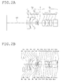
FIGs. 2A and 2B are sectional views taken along the optical axis that show the configuration of the optical system according to Embodiment 1, in a state where simultaneous observation of a front-direction object and a substantially-lateral-direction object is made and in a state where close-up enlarged view observation of the front-direction object is made, respectively. -
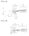
FIGs. 3A and 3B are sectional views taken along the optical axis that show the configuration and path of rays of the optical system according to Embodiment 1, in the state where simultaneous observation of the front-direction object and the substantially-lateral-direction object is made and in the state where close-up enlarged view observation of the front-direction object is made, respectively. -
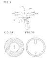
FIG. 4 is an enlarged diagram of the reflecting/refracting optical element included in the optical system according to Embodiment 1. -
FIGs. 5A and 5B are schematic diagrams that show the observation region for the front-direction object and the observation region for the substantially-lateral-direction object in the entire observation region, in the state where simultaneous observation of the front-direction object and the substantially-lateral-direction object is made and in the state where close-up enlarged view observation of the front-direction object is made, respectively. -
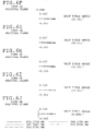
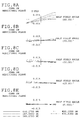
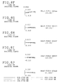
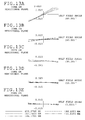
FIGs. 6A-6E andFIGs. 6F-6J are aberration diagrams of the optical system of Embodiment 1 in the state where simultaneous observation of the front-direction object and the substantially-lateral-direction object is made, for rays travelling from the front-direction-object side toward the image pickup surface, specifically showing coma on the meridional plane at the half-field angles of 60°, 45°, 30°, 15° and 0°, and coma on the sagittal plane at the half-field angles of 60°, 45°, 30°, 15° and 0°, respectively. -
FIGs. 7A-7E andFIGs. 7F-7J are aberration diagrams of the optical system of Embodiment 1 in the state where simultaneous observation of the front-direction object and the substantially-lateral-direction object is made, for rays travelling from the substantially-lateral-direction-object side toward the image pickup surface, specifically showing coma on the meridional plane at the half-field angles of 115°, 105°, 95°, 85° and 75°, and coma on the sagittal plane at the half-field angles of 115°, 105°, 95°, 85° and 75°, respectively. -
FIGs. 8A-8E andFIGs. 8F-8J are aberration diagrams of the optical system of Embodiment 1 in the state close-up enlarged view observation of the front-direction object is made, for rays travelling from the front-direction-object side toward the image pickup surface, specifically showing coma on the meridional plane at the half-field angles of 60°, 45°, 30°, 15° and 0°, and coma on the sagittal plane at the half-field angles of 60°, 45°, 30°, 15° and 0°, respectively. -
FIGs. 9A and 9B are sectional views taken along the optical axis that show the configuration of the optical system according to Embodiment 2, in a state where simultaneous observation of a front-direction object and a substantially-lateral-direction object is made and in a state where close-up enlarged view observation of the front-direction object is made, respectively. -
FIGs. 10A and 10B are sectional views taken along the optical axis that show the configuration and path of rays of the optical system according to Embodiment 2, in the state where simultaneous observation of the front-direction object and the substantially-lateral-direction object is made and in the state where close-up enlarged view observation of the front-direction object is made, respectively. -
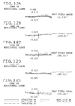
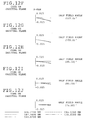
FIGs. 11A-11E andFIGs. 11F-11J are aberration diagrams of the optical system of Embodiment 2 in the state where simultaneous observation of the front-direction object and the substantially-lateral-direction object is made, for rays travelling from the front-direction-object side toward the image pickup surface, specifically showing coma on the meridional plane at the half-field angles of 60°, 45°, 30°, 15° and 0°, and coma on the sagittal plane at the half-field angles of 60°, 45°, 30°, 15° and 0°, respectively. -
FIGs. 12A-12E andFIGs. 12F-12J are aberration diagrams of the optical system of Embodiment 2 in the state where simultaneous observation of the front-direction object and the substantially-lateral-direction object is made, for rays travelling from the substantially-lateral- direction-object side toward the image pickup surface, specifically showing coma on the meridional plane at the half-field angles of 115°, 105°, 95°, 85° and 75°, and coma on the sagittal plane at the half-field angles of 115°, 105°, 95°, 85° and 75°, respectively. -
FIGs. 13A-13E andFIGs. 13F-13J are aberration diagrams of the optical system of Embodiment 2 in the state where close-up enlarged view observation of the front-direction object is made, for rays travelling from the front-direction-object side toward the image pickup surface, specifically showing coma on the meridional plane at the half-field angles of 60°, 45°, 30°, 15° and 0°, and coma on the sagittal plane at the half-field angles of 60°, 45°, 30°, 15° and 0°, respectively. - Preceding explanations of the embodiments of optical systems according to the present invention, function and effect of the configuration of the present invention is explained.
- The optical system of the present invention is provided with a reflecting/refracting optical element having a first face that is formed on the front-direction-object side and that has a first transmitting surface formed with an optical axis being at the center thereof and a firstreflectingsurface annularly formed around the first transmitting surface and directed toward the image side, a second face that is formed on the image side and that has a second transmitting surface formed with the optical axis being at the center thereof and a second reflecting surface annularly formed around the second transmitting surface and directed toward the front-direction-object side, and a third face formed as a transmitting surface between the first face and the second face.
- In this way, since the optical system of the present invention is provided with the reflecting/refracting optical element, it is possible to achieve simultaneous observation of a front-direction object and a substantially-lateral-direction object. Here, the term "reflecting/refracting optical element" means a member that uses the reflecting function and the refracting function of light.
- The optical system of the present invention for observation of a front-direction object and a substantially-lateral-direction object includes, in order from the front-direction-object side, a front group with a negative refracting power having a reflecting/refracting optical element, an aperture stop, and a rear group with a positive refracting power having a moving lens component that is movable in a direction along the optical axis, wherein a movement of the moving lens component changes the refracting power ratio of the front group to the rear group and accordingly enlarges or shrinks, in the entire observation region, a region in which an image of the front-direction object is formed.
- In this way, the optical system of the present invention is constructed as a retrofocus optical system with respect to light coming from the front-direction-object side.
- In a retrofocus optical system, in general, when the negative refracting power of the front group and the positive refracting power of the rear group change, the focal length is changed and, at the same time, the image on the image surface is enlarged or shrunk. Thus, in the optical system of the present invention also, which is constructed as a retrofocus optical system with respect to light coming from the front-direction-object side to enter it, when the moving lens component included in the rear group is moved along the optical axis, the focal length is changed and, at the same time, the region in which the image of the front-direction object is formed is enlarged or shrunk in the entire observation region, because the refracting power ratio of the front group to the rear group is changed.
- That is, the optical system of the present invention is configured to be changeable from an optical system optimized for simultaneous observation of a front-direction object and a substantially-lateral-direction object to an optical system optimized for close-up enlarged view observation of the front-direction object, only by movement the moving lens component in a direction along the optical axis.
- In the optical system of the present invention, it is preferred that the moving lens component has a positive refracting power. In the configuration where the moving lens component included in the rear group has a positive refracting power, it is possible to weaken the negative refracting power of the front group and the positive refracting power of the rear group relative to each other by moving the moving lens component toward the object side. In addition, since the rear group has a positive refracting power as a whole, configuring the moving lens component included in the rear group to have a positive refracting power makes it possible to save the number of lens elements.
- In the optical system of the present invention, it is preferred that, in the rear group, a lens component closest to the aperture stop is the moving lens component. That the lens component closest to the aperture stop in the rear group is the moving lens component means that the moving lens component is close to the front group also. In a configuration where a moving lens component is arranged in such a position, the front group is easily affected by movement of the moving lens component and thus the negative refracting power of the front group also is easily changed. That is, the refracting power of the front lens is sufficiently changeable without a large shift of the moving lens component.
- It is preferred that the optical system of the present invention satisfies the following condition:

where fr_w is a focal length of the rear group in the state where simultaneous observation of the front-direction object and the substantially-lateral-direction object is made, and for is a focal length of the rear group in the state where the region in which an image of the front-direction object is formed in the observation region is enlarged and observed. - If the lower limit of this condition "1.05 < fr_c /f r_w < 1.45" is not reached, the variation of the focal length of the rear group between the state for simultaneous observation of the front-direction object and the substantially-lateral-direction object and the state for close-up enlarged view observation of the front-direction object is too small to appropriately achieve these observation states. On the other hand, if the upper limit is exceeded, the variation of the focal length is too large to keep a good balance between various aberrations.
- In reference to the drawings, optical systems according to Embodiment 1 and Embodiment 2 are explained below.
- The numerical subscripts in r1, r2, ... and d1, d2, ... shown in the sectional views of the optical systems correspond to the surface numbers 1, 2, ... of the numerical data.
- In the numerical data, s denotes surface numbers, r denotes radii of curvature of surfaces, d denotes surface separations, nd denotes refractive indices for d-line rays (wavelength of 587. 56nm), vd denotes Abbe's numbers for d-line rays, k denotes conic constants, and A4, A6, A8 and A10 denote aspherical coefficients.
- Regarding the aspherical coefficients in the numerical data, E denotes a power of ten. For example, "E-01" means ten to the negative first power. The shape of each aspherical surface is expressed by the following expression using the aspherical coefficients shown in the numerical data:

where a coordinate in the direction along the optical axis is represented by Z, and a coordinate in a direction perpendicular to the optical axis is represented by Y. - In the aberration diagrams, the meridional plane is defined as a plane that contains the optical axis of the optical system and a chief ray (a plane parallel to the drawing sheet), and the sagittal plane is defined as a plane that contains the optical axis and is perpendicular to the meridional plane (a plane perpendicular to the drawing sheet) . Since the optical system of the present invention is symmetrical with respect to the meridional plane, plotting of quantity of aberration on the sagittal plane is omitted in the negative domain of the horizontal axis. In each diagram showing coma, the vertical axis represents quantity of aberration, and the horizontal axis represents aperture ratio (-1 to 1). Wavelengths corresponding to the respective lines are indicated in the drawing sheets. For example, the wavelength corresponding to the solid line is 656.27nm.
- In reference to
FIG. 1 , an explanation is made of the definition of angle of view with respect to light entering the reflecting/refracting optical element of the optical system of the present invention as coming from the substantially-lateral-direction-object side.FIG. 1 is a schematic diagram that shows the angle of view with respect to light entering the reflecting/refracting optical element of the present invention as coming from the substantially-lateral-direction-object side. - An angle formed, on the front-direction-object side, between a chief ray of light incident on the third face RLc of the reflecting/refracting optical element RL and the optical axis LC is defined as a half-field angle for the substantially-lateral-direction-object side of the reflecting/refracting optical element RL.
- In the case of such a reflecting/refracting optical element RL, a front-direction object, or an object placed on the optical axis LC cannot be observed via the third face RL c. Therefore, the angle of view should include a minimum angle of view θMin and a maximum angle of view θMax. The minimum angle of view θMin is an angle formed between the most front-direction-object-side chief ray, in a range observable via the third face RLc, and the optical axis. On the other hand, the maximum angle of view θMax is an angle formed between the most image-side chief ray, in the range observable via the third face RL c, and the optical axis.
- In reference to
FIGs. 2 through FIGs. 8 , detailed explanations are made of an optical system according to Embodiment 1. - First, the configuration of the optical system of this embodiment is explained in reference to
FIGs. 2 andFIGs. 3 . - In the optical system of this embodiment, a front group Gf having a negative refracting power as a whole, an aperture stop S, and a rear group Gr having a positive refracting power as a whole are arranged on an optical axis LC of light from the front-direction-object side, in order from the front-direction-object side.
- The front group Gf is composed of, in order from the front-direction-object side, a first lens unit G 1 and a second lens unit G 2.
- The rear group Gr is composed of a third lens unit G 3.
- The first lens unit G 1 is composed of a lens L 1 that is a plano-concave lens with the concave surface thereof being directed toward the image side.
- The second lens unit G 2 includes, in order from the front-direction-object side, a lens L 21 that is a reflecting/refracting optical element with the front-direction-object-side surface thereof being aspherical, a lens L 22 that is a negative meniscus lens with the convex surface thereof being directed toward the image side, and a lens L23 that is a planar lens.
- The aperture stop S is arranged on the image-side surface of the lens L 23 integrally with the lens L 23.
- The third lens unit G 3 includes, in order from the front-direction-object side, a lens L31 that is a biconvex lens movable along the optical axis, a lens L 32 that is a biconvex lens, a lens L 33 that is a biconcave lens, a lens L 34 that is a biconvex lens with the image-side surface thereof being aspherical, and a lens L 35 that is a planar lens. The image-side surface of the lens L 32 and the object-side surface of the lens L 33 are cemented together.
- The shapes of the lenses as referred to are those in the neighborhood of the optical axis of light from the front-direction-object side.
- In reference to
FIG. 4 , detailed explanations are made of the reflecting/refracting optical system provided for simultaneous observation of a front-direction object and a substantially-lateral-direction object. - The lens L 21 as a reflecting/refracting optical element has a first face L21a formed on the front-direction-object side, a second face L 21b formed on the image side, and a third face L 21 c formed on the full circumferential surface between the first face L 21a and the second face L 21b.
- The first face L21a has a first transmitting surface L 21 a 1 formed with the optical axis being at the center thereof and a first reflecting surface L 21 a 2 directed toward the image side and annularly formed around the first transmitting surface L 21 a 1. The second face L 21 b has a second transmitting surface L 21b1 formed with the optical axis being at the center thereof and a second reflecting surface L 21 b 2 directed toward the front-direction-object side and annularly formed around the second transmitting surface L 21 b 1. The third face L 21 c is formed as a transmitting surface over its entire area.
- The first reflecting surface L 21 a 2 and the second reflecting surface L 21 b 2 are made by deposition. To be specific, for example, upon the first transmitting surface L 21 a 1 being masked with a mask having the same contour as the first transmitting surface L21 a 1, the entire first face L21 a is treated with mirror coating and then the mask is removed. By such a method, since the masked portion remains untreated with mirror coating, the first transmitting surface L 21 a 1 can still be used as a transmitting surface even after the first reflecting surface L 21 b 2 is formed.
- In reference to
FIGs. 3 andFIG. 4 , explanations are made of paths followed by light entering the optical system of this embodiment. - Light Lf entering the optical system of this embodiment from the front-direction-object side first passes the lens L 1. Then, the light L f having passed the lens L 1 is incident on the first transmitting surface L 21 a 1 of the lens L21. Then, the light Lf having been incident on the first transmitting surface L 21 a 1 is emergent from the second transmitting surface L 21 b 1 of the lens L 21. The light Lf having being emergent from the second transmitting surface L 21 b 1 passes the lens L 22, the lens L 23, the aperture stop S and the lenses L 31 through L 35 in this order, to form an image of the front-direction object at a center position of an observation region on the image surface.
- On the other hand, light Ls entering the optical system of this embodiment from the substantially-lateral-direction-object side is first incident on the third face L 21 c of the lensL 21. The light Ls having been incident on the third face L21 c is reflected at the second reflecting surface L 21 b 2 of the lens L 21. Then, the light Ls having been reflected at the second reflecting surface L 21 b 2 is reflected at the first reflecting surface L 21 a 2 of the lens L 21. Then, the light Ls having been reflected at the first reflecting surface L 21 a 2 is emergent from the second transmitting surface L 21b1 of the lens L21. The light L s having been emergent from the second transmitting surface L 21 b 1 passes the lens L 22, the lens L 23, the aperture stop S and the lenses L 31 through L 35 in this order, to form an image of the substantially-lateral-direction object annularly around the image of the front-direction object that is formed at the center position of the observation region on the image surface.
- In reference to
FIGs. 3 andFIGs. 5 , explanations are made of the change of the optical system of this embodiment from the state optimized for simultaneous observation of a front-direction object and a substantially-lateral-direction object to the state optimized for close-up enlarged view observation of the front-direction object, and images formed in the observation region in the respective states. - In the state where simultaneous observation of the front-direction object and the substantially-lateral-direction object is made (See
FIG. 3A ), an image of the front-direction object is formed in the central region and an image of the substantially-lateral-direction object is formed in the annular region around the central region (the region indicated by the hatching inFIG. 5A ), in the entire observation region (SeeFIG. 5A ). - The optical system of the present invention is constructed as a retrofocus optical system with respect to light coming from the front-direction-object side. Therefore, when the negative refracting power of the front group Gf and the positive refracting power of the rear group Gr come to be weaker relative to each other than in the state where simultaneous observation of the front-direction object and the substantially-lateral-direction object is made, the region in which the image of the front-direction object is formed is enlarged in the entire observation region, which means that the optical system is brought into the state optimized for close-up enlarged view observation for the front-direction object (See
FIG. 5B ). - The configuration and numerical data are shown below regarding lenses constituting the optical system according to this embodiment.
-
unit: mm Surface data surface number radius of curvature surface separation refractive index Abbe's number s r d nd vd 0 (object surface) D0 1 ∞ 0.7 1.8830 40.8 2 1.98645 0.7 3 (aspherical surface) -17.75837 0.85 1.5163 64.1 4 2.26757 1.787 5 2.7 2.7 6 -1.56527 0.6 1.8830 40.8 7 -1.9108 0.1 8 ∞ 0.4 1.5163 64.1 9 ∞ 0 10 (aperture stop) ∞ D10 11 3.49907 1.4 1.7725 49.6 12 -5.5374 D12 13 24.49464 1.5 1.7292 54.7 14 -2.00692 0.4 1.8467 23.8 15 5.58093 0.1 16 3.18186 1 1.5163 64.1 17 (aspherical surface) -5.08989 0.75 18 ∞ 2 1.5163 64.1 19 ∞ 0 20 (image surface) - It is noted that the radius of curvature for the surface number 5 is a radius of curvature of the third face L 21 c of the lens L 21, that is, the cylindrical surface around the optical axis, and the surface separation for the surface number 5 is a distance from the optical axis to the surface number 5.
Aspherical data surface number radius of curvature conic constant aspherical coefficients s r k A 4 A 6 A 8 A 10 3 -17.75837 0 3.21E-02 -4.74E-03 -5.46E-05 8.59E-05 17 -5.06969 0 2.15E-02 3.34E-02 6.86E-03 -1.45E-03 -
- F number: 6.9
- entire lens length: 14.2mm
- back focal distance: 0mm
- image height: 1.3mm
- half-field angle
- for front-direction-object side
- common to simultaneous observation mode and
- close-up enlarged view observation mode: 69°
- for substantially-lateral-direction-object side (minimum angle - maximum angle)
- simultaneous observation mode: 74° ∼ 116°
- close-up enlarged view observation mode: not measurable
- for front-direction-object side
- focal length
- focal length of entire system for front-direction-object side
- simultaneous observation mode: 0.965mm
- close-up enlarged view observation mode: 1.15746mm
- focal length of first lens unit G 1
- common to simultaneous observation mode and
- close-up enlarged view observation mode: -2.237mm
- focal length of second lens unit G 2 for front-direction-object side
- common to simultaneous observation mode and
- close-up enlarged view observation mode: -3.988mm
- composite focal length of first lens unit G1 and second lens unit G 2
- common to simultaneous observation mode and
- close-up enlarged view observation mode: -1.281mm
- focal length of third lens unit G 3
- simultaneous observation mode (fr_w ): 2.874mm
- close-up enlarged view observation mode (fr_c ) : 3.3551mm
- focal length of moving lens component L 31 (fm )
- common to simultaneous observation mode and
- close-up enlarged view observation mode: 2.963mm
- focal length of entire system for front-direction-object side
-

- In reference to
FIGs. 9 through FIGs. 13 , detailed explanations are made of an optical system according to Embodiment 2. Shape of the reflecting/refracting optical element, paths followed by light entering the optical system, and how to change the observation state in the optical system of this embodiment are substantially the same as those in the optical system of Embodiment 1, members having substantially same configurations are labeled with same symbols and detailed explanations on these are omitted. - First, the configuration of the optical system of this embodiment is explained in reference to
FIGs. 9 andFIGs. 10 . - In the optical system of this embodiment, a front group Gf having a negative refracting power as a whole, an aperture stop S, and a rear group Gr having a positive refracting power as a whole are arranged on an optical axis LC of light from the front-direction-object side, in order from the front-direction-object side.
- The front group Gf is composed of, in order from the front-direction-object side, a first lens unit G 1 and a second lens unit G2.
- The rear group Gr is composed of a third lens unit G 3.
- The first lens unit G 1 is composed of a lens L 1 that is a plano-concave lens with the concave surface thereof being directed toward the image side.
- The second lens unit G 2 includes, in order from the front-direction-object side, a lens L 21 that is a reflecting/refracting optical element with the front-direction-object-side surface thereof being aspherical and a lens L 22 that is a planar lens.
- The aperture stop S is arranged on the image side of the lens L 22.
- The third lens unit G 3 includes, in order from the front-direction-object side, a lens L 31 that is a biconvex lens movable along the optical axis, a lens L 32 that is a positive meniscus lens with the convex surface thereof being directed toward the image side, a lens L 33 that is a biconcave lens, a lens L 34 that is a biconvex lens with the image-side surface thereof being aspherical, and a lens L 35 that is a planar lens. The image-side surface of the lens L 32 and the object-side surface of the lens L 33 are cemented together.
- The shapes of the lenses as referred to are those in the neighborhood of the optical axis of light from the front-direction-object side.
- The configuration and numerical data are shown below regarding lenses constituting the optical system according to this embodiment.
-
unit: mm Surface data surface number radius of curvature surface separation refractive index Abbe's number s r d nd vd 0 (object surface) D0 1 ∞ 0.7 1.5163 64.1 2 1.58699 0.9 3 (aspherical surface) 114.08067 0.85 1.5163 64.1 4 2.2 2.6138 5 3 3 6 ∞ 0.6 1.8830 40.8 7 ∞ 0.287 8 (aperture stop) ∞ D8 9 5.00915 1.4 1.7725 49.6 10 -3.89454 D10 11 -23.93361 1.7 1.7292 54.7 12 -2.15 0.4 1.8467 23.8 13 10781.23595 0.1 14 7.53056 1.25 1.5163 64.1 15 (aspherical surface) -3.46941 0.85 16 ∞ 2 1.5163 64.1 17 ∞ 0 18 (image surface) - It is noted that the radius of curvature for the surface number 5 is a radius of curvature of the third face L 21c of the lens L 21, that is, the cylindrical surface around the optical axis, and the surface separation for the surface number 5 is a distance from the optical axis to the surface number 5.
Aspherical data surface number radius of curvature conic constant aspherical coefficients s r k A 4 A 6 A 8 A 10 3 114.08067 0 2.08E-02 -4.13E-03 -5.76E-05 -3.53E-05 15 -3.46941 0 2.45E-02 5.44E-03 9.28E-03 -1.55E-03 -
- F number: 5.3
- entire lens length: 15.5mm
- back focal distance: 0mm
- image height: 1.3mm
- half-field angle
- for front-direction-object side
- common to simultaneous observation mode and
- close-up enlarged view observation mode: 60°
- for substantially-lateral-direction-object side (minimum angle - maximum angle)
- simultaneous observation mode: 72° ∼ 118°
- close-up enlarged view observation mode: not measurable
- for front-direction-object side
- focal length
- focal length of entire system for front-direction-object side
- simultaneous observation mode: 0.754mm
- close-up enlarged view observation mode: 1.154mm
- focal length of first lens unit G1
- common to simultaneous observation mode and
- close-up enlarged view observation mode: -3.062mm
- focal length of second lens unit G2 for front-direction-object side
- common to simultaneous observation mode and
- close-up enlarged view observation mode: -4.340mm
- composite focal length of first lens unit G 1 and second lens unit G 2
- common to simultaneous observation mode and
- close-up enlarged view observation mode: -1.497mm
- focal length of third lens unit G 3
- simultaneous observation mode (f r_ w): 2.978mm
- close-up enlarged view observation mode (f r_c): 3.740mm
- focal length of moving lens component L 31 (f m)
- common to simultaneous observation mode and
- close-up enlarged view observation mode: 3.031mm
- focal length of entire system for front-direction-object side
-

- In the descriptions of the embodiments above, the close-up enlarged view observation is referred to only with respect to the front-direction object. However, the optical system may be configured to achieve close-up enlarged view observation of a substantially-lateral-direction object.
- Further, the optical system may be provided with a moving lens other than the moving lens component described in each of the embodiments above, for varying the magnification with respect to the image of the front-direction object formed in the observation region by moving this moving lens.
- In each of the above-described embodiments, for close-up enlarged view observation, the moving lens component is moved up to a position where an image of the substantially-lateral-direction object is scarcely formed. However, the moving lens component may be moved to a position that allows an image of the substantially-lateral-direction object to be formed to some extent in the entire observation region in close-up enlarged view observation also. In other words, although each of the above-described embodiments shows only the two extreme states of the optical system, or the state for simultaneous observation of a front-direction object and a substantially-lateral-direction object and the state for close-up enlarged view observation of the front-direction object, the optical system may be used with the moving lens component being positioned for an intermediate state between these extreme states, as a matter of course.
- In the above-described embodiments, there is no mention of focusing in the state for simultaneous observation of the front-direction object and the substantially-lateral-direction object or in the state for close-up enlarged view observation of the front-direction object. Focusing may be made, for example, by moving the moving lens component to an extent as not to greatly change the refracting power balance between the front group and the rear group.
- Regarding lenses constituting an optical system of the present invention, shapes and numbers are not limited to those disclosed in the above-described embodiments. Various optical systems including reflecting/refracting optical elements also are in the scope.
- Although not arranged in the above-described embodiments, an image sensor may be arranged on the image side of the optical system. Further, a lowpass filter treated with IR cutoff coating, a CCD cover glass and the like may be arranged between the optical system and this image sensor.
- While each of the optical systems is composed of three lens units in the above-described embodiments, an optical system of the present invention is not limited to these examples, but may be composed of two lens units or more than four lens units.
- In the above-described embodiments, the third face of the reflecting/refracting optical element is shaped such that its front-direction-object-side diameter substantially coincides with its image-side diameter. However, those shaped to have the image-side diameter larger than the front-direction-object-side diameter or to have the image-side diameter smaller than the front-direction-object-side diameter may be used. The front-direction-object-side diameter is defined as a diameter measured at the most front-direction-object-side position of the third face in a plane perpendicular to the optical axis, and the image-side diameter is defined as a diameter measured at the most image-side position of the third face in a plane perpendicular to the optical axis. Further, while the third face of the reflecting/refracting optical element is formed between the first face and the second face over the entire circumferential face in the above-described embodiments, it is not always necessary to be formed over the entire circumferential face, but may be formed as a transmitting surface only in a partial region of the circumferential face.
- Further, in each of the above-described embodiments, the first reflecting surface and the second reflecting surface are formed by deposition. However, forming method is not limited to this.
| surface separation | ||
| simultaneous observation | close-up enlarged view observation | |
| D0 | 9.440 | 1.505 |
| D10 | 1.814 | 0.1 |
| D12 | 0.1 | 1.814 |
| surface separation | ||
| simultaneous observation | close-up enlarged view observation | |
| D0 | 10.828 | 1.206 |
| D8 | 1.749 | 0.339 |
| D10 | 0.1 | 1.510 |
Claims (6)
- An optical system for observation of a front-direction object and a substantially-lateral-direction object, the optical system comprising, in order from a front-direction-object side:a front group (Gf ) with a negative refracting power having a reflecting/refracting optical element (L 21);an aperture stop (S); anda rear group (Gr ) with a positive refracting power having a moving lens component (L 31) that is movable along an optical axis (LC) ;characterized in that the reflecting/refracting optical element (L21) has:a first face (L 21 a) that is formedon the front-direction-object side and that has a first transmitting surface (L 21 a 1) formed with the optical axis being at a center thereof and a first reflecting surface (L 21 a 2) annularly formed around the first transmitting surface (L 21 a 1) and directed toward an image side,a second face (L 21 b) that is formed on the image side and that has a second transmitting surface (L 21 b 1) formed with the optical axis being at a center thereof and a second reflecting surface (L 21 b 2) annularly formed around the second transmitting surface (L 21 b 1) and directed toward the front-direction-object side, anda third face (L 21 c) formed as a transmitting surface between the first face (L 21 a) and the second face (L 21 b), andin that a movement of the moving lens component (L 31) changes a refracting power ratio of the front group (Gf ) to the rear group (Gr ) , to enlarge or shrink, in an observation region, a region in which an image of the front-direction object is formed.
- An optical system according to claim 1,
characterized in that the moving lens component (L 31) has a positive refracting power. - An optical system according to claim 1,
characterized in that, in the rear group (Gr ), a lens component closest to the aperture stop is the moving lens component (L 31). - An optical system according to claim 1,
characterized in that the front group (Gf ) includes a first lens unit (G 1) with a negative refracting power and a second lens unit (G 2),
in that the rear group (Gr ) includes a third lens unit (G3 ) with a positive refracting power,
in that the first lens unit (G 1) , the second lens unit (G 2), the aperture stop (5) and the third lens unit (G 3) form a first optical system for observation of the front-direction object, and
in that the second lens unit (G 2), the aperture stop (S) and the third lens unit (G 3) form a second optical system for observation of the substantially-lateral-direction object. - An optical system according to claim 1,
characterized in that light from the front-direction-object side, after being incident on the first transmitting surface (L 21 a 1) , is made emergent toward the image side from the second transmitting surface (L 21 b 1), and
in that light from the substantially-lateral-direction-object side, after being incident on the third face (L 21 c) is sequentially reflected at the second reflecting surface (L 21 b 2) and the first reflecting surface (L 21 a 2) and is made emergent toward the image side from the second transmitting surface (L 21 b 1)' - An optical system according to claim 1, characterized in that the following condition is satisfied:

where fr_w is a focal length of the rear group (Gr) in a state where simultaneous observation of the front-direction object and the substantially-lateral-direction object is made, and fr_c is a focal length of the rear group (Gr ) in a state where the region in which the image of the front-direction object is formed in the observation region is enlarged and observed.
Priority Applications (1)
| Application Number | Priority Date | Filing Date | Title |
|---|---|---|---|
| EP11001459.4A EP2492733B1 (en) | 2011-02-22 | 2011-02-22 | Optical system |
Applications Claiming Priority (1)
| Application Number | Priority Date | Filing Date | Title |
|---|---|---|---|
| EP11001459.4A EP2492733B1 (en) | 2011-02-22 | 2011-02-22 | Optical system |
Publications (2)
| Publication Number | Publication Date |
|---|---|
| EP2492733A1 true EP2492733A1 (en) | 2012-08-29 |
| EP2492733B1 EP2492733B1 (en) | 2017-06-07 |
Family
ID=43982414
Family Applications (1)
| Application Number | Title | Priority Date | Filing Date |
|---|---|---|---|
| EP11001459.4A Not-in-force EP2492733B1 (en) | 2011-02-22 | 2011-02-22 | Optical system |
Country Status (1)
| Country | Link |
|---|---|
| EP (1) | EP2492733B1 (en) |
Cited By (1)
| Publication number | Priority date | Publication date | Assignee | Title |
|---|---|---|---|---|
| JP2014106327A (en) * | 2012-11-27 | 2014-06-09 | Olympus Corp | Optical element, optical system, stereoscopic imaging apparatus and endoscope |
Citations (3)
| Publication number | Priority date | Publication date | Assignee | Title |
|---|---|---|---|---|
| EP1452899A1 (en) * | 2001-11-13 | 2004-09-01 | Matsushita Electric Industrial Co., Ltd. | Wide-angle imaging optical system and wide-angle imaging device, monitoring imaging device, on-vehicle imaging device and projection device with the wide-angle imaging optical system |
| JP2008309859A (en) | 2007-06-12 | 2008-12-25 | Olympus Corp | Optical system and endoscope using the same |
| WO2010084915A1 (en) * | 2009-01-21 | 2010-07-29 | オリンパス株式会社 | Optical system |
-
2011
- 2011-02-22 EP EP11001459.4A patent/EP2492733B1/en not_active Not-in-force
Patent Citations (3)
| Publication number | Priority date | Publication date | Assignee | Title |
|---|---|---|---|---|
| EP1452899A1 (en) * | 2001-11-13 | 2004-09-01 | Matsushita Electric Industrial Co., Ltd. | Wide-angle imaging optical system and wide-angle imaging device, monitoring imaging device, on-vehicle imaging device and projection device with the wide-angle imaging optical system |
| JP2008309859A (en) | 2007-06-12 | 2008-12-25 | Olympus Corp | Optical system and endoscope using the same |
| WO2010084915A1 (en) * | 2009-01-21 | 2010-07-29 | オリンパス株式会社 | Optical system |
Cited By (1)
| Publication number | Priority date | Publication date | Assignee | Title |
|---|---|---|---|---|
| JP2014106327A (en) * | 2012-11-27 | 2014-06-09 | Olympus Corp | Optical element, optical system, stereoscopic imaging apparatus and endoscope |
Also Published As
| Publication number | Publication date |
|---|---|
| EP2492733B1 (en) | 2017-06-07 |
Similar Documents
| Publication | Publication Date | Title |
|---|---|---|
| US10473899B2 (en) | Optical imaging system | |
| US10302904B2 (en) | Optical imaging system | |
| JP5479818B2 (en) | Optical system and endoscope apparatus including the same | |
| JP5496809B2 (en) | Imaging lens and imaging apparatus | |
| TWI436124B (en) | Optical imaging lens assembly | |
| US8331039B2 (en) | Optical system | |
| US8310769B2 (en) | Optical system | |
| CN102253470B (en) | Photography Optical Lens | |
| US11119293B2 (en) | Imaging lens system | |
| KR20160022908A (en) | Lenses for curved sensor systems | |
| JP2018013579A (en) | Imaging lens and imaging apparatus | |
| EP2579081B1 (en) | Telescope optical system and optical device provided therewith | |
| EP2385407B1 (en) | Optical system | |
| CN107966785B (en) | camera lens | |
| US20090310230A1 (en) | Transmitting optical element and optical system using the same | |
| JP5624909B2 (en) | Microscope objective lens and microscope apparatus provided with the same | |
| US7253972B2 (en) | Telephoto lens system | |
| JP6230518B2 (en) | Endoscope objective optical system | |
| US8284494B2 (en) | Optical system | |
| CN112424669A (en) | Eyepiece optical system and head-mounted display | |
| JP2013137341A (en) | Imaging lens | |
| US20190212534A1 (en) | Optical imaging lens | |
| CN101833160A (en) | Image pickup optical lens group | |
| EP2492733B1 (en) | Optical system | |
| US11385444B2 (en) | Micro lens assembly for short-range imaging |
Legal Events
| Date | Code | Title | Description |
|---|---|---|---|
| PUAI | Public reference made under article 153(3) epc to a published international application that has entered the european phase |
Free format text: ORIGINAL CODE: 0009012 |
|
| AK | Designated contracting states |
Kind code of ref document: A1 Designated state(s): AL AT BE BG CH CY CZ DE DK EE ES FI FR GB GR HR HU IE IS IT LI LT LU LV MC MK MT NL NO PL PT RO RS SE SI SK SM TR |
|
| AX | Request for extension of the european patent |
Extension state: BA ME |
|
| 17P | Request for examination filed |
Effective date: 20121227 |
|
| RAP1 | Party data changed (applicant data changed or rights of an application transferred) |
Owner name: OLYMPUS CORPORATION |
|
| RIN1 | Information on inventor provided before grant (corrected) |
Inventor name: MIZUSAWA, MASAYUKI |
|
| GRAP | Despatch of communication of intention to grant a patent |
Free format text: ORIGINAL CODE: EPIDOSNIGR1 |
|
| STAA | Information on the status of an ep patent application or granted ep patent |
Free format text: STATUS: GRANT OF PATENT IS INTENDED |
|
| INTG | Intention to grant announced |
Effective date: 20161206 |
|
| GRAS | Grant fee paid |
Free format text: ORIGINAL CODE: EPIDOSNIGR3 |
|
| GRAJ | Information related to disapproval of communication of intention to grant by the applicant or resumption of examination proceedings by the epo deleted |
Free format text: ORIGINAL CODE: EPIDOSDIGR1 |
|
| GRAL | Information related to payment of fee for publishing/printing deleted |
Free format text: ORIGINAL CODE: EPIDOSDIGR3 |
|
| STAA | Information on the status of an ep patent application or granted ep patent |
Free format text: STATUS: REQUEST FOR EXAMINATION WAS MADE |
|
| GRAR | Information related to intention to grant a patent recorded |
Free format text: ORIGINAL CODE: EPIDOSNIGR71 |
|
| STAA | Information on the status of an ep patent application or granted ep patent |
Free format text: STATUS: GRANT OF PATENT IS INTENDED |
|
| GRAA | (expected) grant |
Free format text: ORIGINAL CODE: 0009210 |
|
| STAA | Information on the status of an ep patent application or granted ep patent |
Free format text: STATUS: THE PATENT HAS BEEN GRANTED |
|
| INTC | Intention to grant announced (deleted) | ||
| AK | Designated contracting states |
Kind code of ref document: B1 Designated state(s): AL AT BE BG CH CY CZ DE DK EE ES FI FR GB GR HR HU IE IS IT LI LT LU LV MC MK MT NL NO PL PT RO RS SE SI SK SM TR |
|
| INTG | Intention to grant announced |
Effective date: 20170428 |
|
| REG | Reference to a national code |
Ref country code: GB Ref legal event code: FG4D |
|
| GRAA | (expected) grant |
Free format text: ORIGINAL CODE: 0009210 |
|
| REG | Reference to a national code |
Ref country code: CH Ref legal event code: EP Ref country code: AT Ref legal event code: REF Ref document number: 899655 Country of ref document: AT Kind code of ref document: T Effective date: 20170615 |
|
| REG | Reference to a national code |
Ref country code: IE Ref legal event code: FG4D |
|
| REG | Reference to a national code |
Ref country code: DE Ref legal event code: R096 Ref document number: 602011038468 Country of ref document: DE |
|
| REG | Reference to a national code |
Ref country code: NL Ref legal event code: MP Effective date: 20170607 |
|
| REG | Reference to a national code |
Ref country code: LT Ref legal event code: MG4D |
|
| PG25 | Lapsed in a contracting state [announced via postgrant information from national office to epo] |
Ref country code: LT Free format text: LAPSE BECAUSE OF FAILURE TO SUBMIT A TRANSLATION OF THE DESCRIPTION OR TO PAY THE FEE WITHIN THE PRESCRIBED TIME-LIMIT Effective date: 20170607 Ref country code: FI Free format text: LAPSE BECAUSE OF FAILURE TO SUBMIT A TRANSLATION OF THE DESCRIPTION OR TO PAY THE FEE WITHIN THE PRESCRIBED TIME-LIMIT Effective date: 20170607 Ref country code: ES Free format text: LAPSE BECAUSE OF FAILURE TO SUBMIT A TRANSLATION OF THE DESCRIPTION OR TO PAY THE FEE WITHIN THE PRESCRIBED TIME-LIMIT Effective date: 20170607 Ref country code: NO Free format text: LAPSE BECAUSE OF FAILURE TO SUBMIT A TRANSLATION OF THE DESCRIPTION OR TO PAY THE FEE WITHIN THE PRESCRIBED TIME-LIMIT Effective date: 20170907 Ref country code: HR Free format text: LAPSE BECAUSE OF FAILURE TO SUBMIT A TRANSLATION OF THE DESCRIPTION OR TO PAY THE FEE WITHIN THE PRESCRIBED TIME-LIMIT Effective date: 20170607 Ref country code: GR Free format text: LAPSE BECAUSE OF FAILURE TO SUBMIT A TRANSLATION OF THE DESCRIPTION OR TO PAY THE FEE WITHIN THE PRESCRIBED TIME-LIMIT Effective date: 20170908 |
|
| REG | Reference to a national code |
Ref country code: AT Ref legal event code: MK05 Ref document number: 899655 Country of ref document: AT Kind code of ref document: T Effective date: 20170607 |
|
| PG25 | Lapsed in a contracting state [announced via postgrant information from national office to epo] |
Ref country code: BG Free format text: LAPSE BECAUSE OF FAILURE TO SUBMIT A TRANSLATION OF THE DESCRIPTION OR TO PAY THE FEE WITHIN THE PRESCRIBED TIME-LIMIT Effective date: 20170907 Ref country code: SE Free format text: LAPSE BECAUSE OF FAILURE TO SUBMIT A TRANSLATION OF THE DESCRIPTION OR TO PAY THE FEE WITHIN THE PRESCRIBED TIME-LIMIT Effective date: 20170607 Ref country code: RS Free format text: LAPSE BECAUSE OF FAILURE TO SUBMIT A TRANSLATION OF THE DESCRIPTION OR TO PAY THE FEE WITHIN THE PRESCRIBED TIME-LIMIT Effective date: 20170607 Ref country code: NL Free format text: LAPSE BECAUSE OF FAILURE TO SUBMIT A TRANSLATION OF THE DESCRIPTION OR TO PAY THE FEE WITHIN THE PRESCRIBED TIME-LIMIT Effective date: 20170607 Ref country code: LV Free format text: LAPSE BECAUSE OF FAILURE TO SUBMIT A TRANSLATION OF THE DESCRIPTION OR TO PAY THE FEE WITHIN THE PRESCRIBED TIME-LIMIT Effective date: 20170607 |
|
| PG25 | Lapsed in a contracting state [announced via postgrant information from national office to epo] |
Ref country code: SK Free format text: LAPSE BECAUSE OF FAILURE TO SUBMIT A TRANSLATION OF THE DESCRIPTION OR TO PAY THE FEE WITHIN THE PRESCRIBED TIME-LIMIT Effective date: 20170607 Ref country code: EE Free format text: LAPSE BECAUSE OF FAILURE TO SUBMIT A TRANSLATION OF THE DESCRIPTION OR TO PAY THE FEE WITHIN THE PRESCRIBED TIME-LIMIT Effective date: 20170607 Ref country code: AT Free format text: LAPSE BECAUSE OF FAILURE TO SUBMIT A TRANSLATION OF THE DESCRIPTION OR TO PAY THE FEE WITHIN THE PRESCRIBED TIME-LIMIT Effective date: 20170607 Ref country code: RO Free format text: LAPSE BECAUSE OF FAILURE TO SUBMIT A TRANSLATION OF THE DESCRIPTION OR TO PAY THE FEE WITHIN THE PRESCRIBED TIME-LIMIT Effective date: 20170607 Ref country code: CZ Free format text: LAPSE BECAUSE OF FAILURE TO SUBMIT A TRANSLATION OF THE DESCRIPTION OR TO PAY THE FEE WITHIN THE PRESCRIBED TIME-LIMIT Effective date: 20170607 |
|
| PG25 | Lapsed in a contracting state [announced via postgrant information from national office to epo] |
Ref country code: PL Free format text: LAPSE BECAUSE OF FAILURE TO SUBMIT A TRANSLATION OF THE DESCRIPTION OR TO PAY THE FEE WITHIN THE PRESCRIBED TIME-LIMIT Effective date: 20170607 Ref country code: IS Free format text: LAPSE BECAUSE OF FAILURE TO SUBMIT A TRANSLATION OF THE DESCRIPTION OR TO PAY THE FEE WITHIN THE PRESCRIBED TIME-LIMIT Effective date: 20171007 Ref country code: IT Free format text: LAPSE BECAUSE OF FAILURE TO SUBMIT A TRANSLATION OF THE DESCRIPTION OR TO PAY THE FEE WITHIN THE PRESCRIBED TIME-LIMIT Effective date: 20170607 Ref country code: SM Free format text: LAPSE BECAUSE OF FAILURE TO SUBMIT A TRANSLATION OF THE DESCRIPTION OR TO PAY THE FEE WITHIN THE PRESCRIBED TIME-LIMIT Effective date: 20170607 |
|
| REG | Reference to a national code |
Ref country code: DE Ref legal event code: R097 Ref document number: 602011038468 Country of ref document: DE |
|
| PLBE | No opposition filed within time limit |
Free format text: ORIGINAL CODE: 0009261 |
|
| STAA | Information on the status of an ep patent application or granted ep patent |
Free format text: STATUS: NO OPPOSITION FILED WITHIN TIME LIMIT |
|
| PG25 | Lapsed in a contracting state [announced via postgrant information from national office to epo] |
Ref country code: DK Free format text: LAPSE BECAUSE OF FAILURE TO SUBMIT A TRANSLATION OF THE DESCRIPTION OR TO PAY THE FEE WITHIN THE PRESCRIBED TIME-LIMIT Effective date: 20170607 |
|
| 26N | No opposition filed |
Effective date: 20180308 |
|
| PG25 | Lapsed in a contracting state [announced via postgrant information from national office to epo] |
Ref country code: SI Free format text: LAPSE BECAUSE OF FAILURE TO SUBMIT A TRANSLATION OF THE DESCRIPTION OR TO PAY THE FEE WITHIN THE PRESCRIBED TIME-LIMIT Effective date: 20170607 |
|
| REG | Reference to a national code |
Ref country code: CH Ref legal event code: PL |
|
| PG25 | Lapsed in a contracting state [announced via postgrant information from national office to epo] |
Ref country code: MC Free format text: LAPSE BECAUSE OF FAILURE TO SUBMIT A TRANSLATION OF THE DESCRIPTION OR TO PAY THE FEE WITHIN THE PRESCRIBED TIME-LIMIT Effective date: 20170607 |
|
| GBPC | Gb: european patent ceased through non-payment of renewal fee |
Effective date: 20180222 |
|
| REG | Reference to a national code |
Ref country code: IE Ref legal event code: MM4A |
|
| REG | Reference to a national code |
Ref country code: BE Ref legal event code: MM Effective date: 20180228 |
|
| PG25 | Lapsed in a contracting state [announced via postgrant information from national office to epo] |
Ref country code: CH Free format text: LAPSE BECAUSE OF NON-PAYMENT OF DUE FEES Effective date: 20180228 Ref country code: LI Free format text: LAPSE BECAUSE OF NON-PAYMENT OF DUE FEES Effective date: 20180228 Ref country code: LU Free format text: LAPSE BECAUSE OF NON-PAYMENT OF DUE FEES Effective date: 20180222 |
|
| REG | Reference to a national code |
Ref country code: FR Ref legal event code: ST Effective date: 20181031 |
|
| PG25 | Lapsed in a contracting state [announced via postgrant information from national office to epo] |
Ref country code: IE Free format text: LAPSE BECAUSE OF NON-PAYMENT OF DUE FEES Effective date: 20180222 |
|
| PG25 | Lapsed in a contracting state [announced via postgrant information from national office to epo] |
Ref country code: GB Free format text: LAPSE BECAUSE OF NON-PAYMENT OF DUE FEES Effective date: 20180222 Ref country code: FR Free format text: LAPSE BECAUSE OF NON-PAYMENT OF DUE FEES Effective date: 20180228 Ref country code: BE Free format text: LAPSE BECAUSE OF NON-PAYMENT OF DUE FEES Effective date: 20180228 |
|
| PGFP | Annual fee paid to national office [announced via postgrant information from national office to epo] |
Ref country code: DE Payment date: 20190219 Year of fee payment: 9 |
|
| PG25 | Lapsed in a contracting state [announced via postgrant information from national office to epo] |
Ref country code: MT Free format text: LAPSE BECAUSE OF NON-PAYMENT OF DUE FEES Effective date: 20180222 |
|
| PG25 | Lapsed in a contracting state [announced via postgrant information from national office to epo] |
Ref country code: TR Free format text: LAPSE BECAUSE OF FAILURE TO SUBMIT A TRANSLATION OF THE DESCRIPTION OR TO PAY THE FEE WITHIN THE PRESCRIBED TIME-LIMIT Effective date: 20170607 |
|
| PG25 | Lapsed in a contracting state [announced via postgrant information from national office to epo] |
Ref country code: PT Free format text: LAPSE BECAUSE OF FAILURE TO SUBMIT A TRANSLATION OF THE DESCRIPTION OR TO PAY THE FEE WITHIN THE PRESCRIBED TIME-LIMIT Effective date: 20170607 Ref country code: HU Free format text: LAPSE BECAUSE OF FAILURE TO SUBMIT A TRANSLATION OF THE DESCRIPTION OR TO PAY THE FEE WITHIN THE PRESCRIBED TIME-LIMIT; INVALID AB INITIO Effective date: 20110222 |
|
| PG25 | Lapsed in a contracting state [announced via postgrant information from national office to epo] |
Ref country code: MK Free format text: LAPSE BECAUSE OF NON-PAYMENT OF DUE FEES Effective date: 20170607 Ref country code: CY Free format text: LAPSE BECAUSE OF FAILURE TO SUBMIT A TRANSLATION OF THE DESCRIPTION OR TO PAY THE FEE WITHIN THE PRESCRIBED TIME-LIMIT Effective date: 20170607 |
|
| PG25 | Lapsed in a contracting state [announced via postgrant information from national office to epo] |
Ref country code: AL Free format text: LAPSE BECAUSE OF FAILURE TO SUBMIT A TRANSLATION OF THE DESCRIPTION OR TO PAY THE FEE WITHIN THE PRESCRIBED TIME-LIMIT Effective date: 20170607 |
|
| REG | Reference to a national code |
Ref country code: DE Ref legal event code: R119 Ref document number: 602011038468 Country of ref document: DE |
|
| PG25 | Lapsed in a contracting state [announced via postgrant information from national office to epo] |
Ref country code: DE Free format text: LAPSE BECAUSE OF NON-PAYMENT OF DUE FEES Effective date: 20200901 |