EP2492677A1 - Sample introducing device for ion mobility spectrometer, method using it and ion mobility spectrometer - Google Patents
Sample introducing device for ion mobility spectrometer, method using it and ion mobility spectrometer Download PDFInfo
- Publication number
- EP2492677A1 EP2492677A1 EP11726316A EP11726316A EP2492677A1 EP 2492677 A1 EP2492677 A1 EP 2492677A1 EP 11726316 A EP11726316 A EP 11726316A EP 11726316 A EP11726316 A EP 11726316A EP 2492677 A1 EP2492677 A1 EP 2492677A1
- Authority
- EP
- European Patent Office
- Prior art keywords
- end cap
- detected
- sample
- cavity
- opening
- Prior art date
- Legal status (The legal status is an assumption and is not a legal conclusion. Google has not performed a legal analysis and makes no representation as to the accuracy of the status listed.)
- Granted
Links
- 238000000034 method Methods 0.000 title claims abstract description 33
- 238000013508 migration Methods 0.000 claims abstract description 117
- 230000005012 migration Effects 0.000 claims abstract description 117
- 238000005070 sampling Methods 0.000 claims abstract description 112
- 239000007787 solid Substances 0.000 claims abstract description 41
- 239000007789 gas Substances 0.000 claims description 91
- 238000010438 heat treatment Methods 0.000 claims description 38
- 239000000463 material Substances 0.000 claims description 20
- 239000012528 membrane Substances 0.000 claims description 17
- 230000008569 process Effects 0.000 claims description 15
- 238000004094 preconcentration Methods 0.000 claims description 11
- 239000003463 adsorbent Substances 0.000 claims description 7
- 239000012159 carrier gas Substances 0.000 claims description 4
- 238000009413 insulation Methods 0.000 claims description 3
- 238000000926 separation method Methods 0.000 claims description 3
- 238000001914 filtration Methods 0.000 claims 1
- 239000000523 sample Substances 0.000 description 82
- 150000002500 ions Chemical class 0.000 description 56
- 239000002245 particle Substances 0.000 description 15
- 238000013461 design Methods 0.000 description 7
- 238000001514 detection method Methods 0.000 description 7
- 230000009471 action Effects 0.000 description 6
- 238000010586 diagram Methods 0.000 description 6
- 230000009102 absorption Effects 0.000 description 4
- 238000010521 absorption reaction Methods 0.000 description 4
- 238000003795 desorption Methods 0.000 description 4
- 238000005516 engineering process Methods 0.000 description 4
- 239000002360 explosive Substances 0.000 description 4
- 230000035945 sensitivity Effects 0.000 description 4
- 238000006243 chemical reaction Methods 0.000 description 3
- 230000005684 electric field Effects 0.000 description 3
- 239000013307 optical fiber Substances 0.000 description 3
- 238000009833 condensation Methods 0.000 description 2
- 230000005494 condensation Effects 0.000 description 2
- 238000010276 construction Methods 0.000 description 2
- 230000008021 deposition Effects 0.000 description 2
- 238000000151 deposition Methods 0.000 description 2
- 239000003814 drug Substances 0.000 description 2
- 229940079593 drug Drugs 0.000 description 2
- 230000000694 effects Effects 0.000 description 2
- 239000007769 metal material Substances 0.000 description 2
- 230000002093 peripheral effect Effects 0.000 description 2
- 229920000260 silastic Polymers 0.000 description 2
- 239000007790 solid phase Substances 0.000 description 2
- 238000001228 spectrum Methods 0.000 description 2
- 229910001220 stainless steel Inorganic materials 0.000 description 2
- 239000010935 stainless steel Substances 0.000 description 2
- 238000012360 testing method Methods 0.000 description 2
- OKTJSMMVPCPJKN-UHFFFAOYSA-N Carbon Chemical compound [C] OKTJSMMVPCPJKN-UHFFFAOYSA-N 0.000 description 1
- 206010013975 Dyspnoeas Diseases 0.000 description 1
- 230000003213 activating effect Effects 0.000 description 1
- 239000000969 carrier Substances 0.000 description 1
- 230000008859 change Effects 0.000 description 1
- 231100000481 chemical toxicant Toxicity 0.000 description 1
- 239000011248 coating agent Substances 0.000 description 1
- 238000000576 coating method Methods 0.000 description 1
- 230000001010 compromised effect Effects 0.000 description 1
- 125000004122 cyclic group Chemical group 0.000 description 1
- 230000007547 defect Effects 0.000 description 1
- 239000002019 doping agent Substances 0.000 description 1
- 230000002349 favourable effect Effects 0.000 description 1
- 238000007689 inspection Methods 0.000 description 1
- 230000007246 mechanism Effects 0.000 description 1
- 230000003340 mental effect Effects 0.000 description 1
- 239000002184 metal Substances 0.000 description 1
- 238000002156 mixing Methods 0.000 description 1
- 239000000203 mixture Substances 0.000 description 1
- 238000012986 modification Methods 0.000 description 1
- 230000004048 modification Effects 0.000 description 1
- 239000012466 permeate Substances 0.000 description 1
- 230000035485 pulse pressure Effects 0.000 description 1
- 239000010421 standard material Substances 0.000 description 1
- 239000003440 toxic substance Substances 0.000 description 1
- 238000010792 warming Methods 0.000 description 1
Images

Classifications
-
- G—PHYSICS
- G01—MEASURING; TESTING
- G01N—INVESTIGATING OR ANALYSING MATERIALS BY DETERMINING THEIR CHEMICAL OR PHYSICAL PROPERTIES
- G01N27/00—Investigating or analysing materials by the use of electric, electrochemical, or magnetic means
- G01N27/62—Investigating or analysing materials by the use of electric, electrochemical, or magnetic means by investigating the ionisation of gases, e.g. aerosols; by investigating electric discharges, e.g. emission of cathode
- G01N27/622—Ion mobility spectrometry
Definitions
- the present invention relates to the field of ion migration detection technologies, and in particular, to a sampling device for an ion migration spectrometer and a method for detecting samples to be detected of solid particles and gas by using said sampling device. Moreover, the invention further relates to an ion migration spectrometer provided with the above sampling device.
- a detecting instrument based on ion migration spectrum (IMS) technologies may be used for detecting trace-level prohibited articles such as explosives, drugs and toxic chemicals, etc.. Due to the characteristics of quick speed, sensitiveness and portability, etc., such detecting instrument has now been widely used in military and safety inspection fields.
- Most of the commercialized portable IMS instruments adopt two sampling methods, that is, solid sampling or wiping sampling, and gas sampling.
- the former collects particles to be detected by wiping the surface of a suspicious object with a clean sampling carrier, for example, wipe paper, then puts the wipe paper or the sampling carrier adhering with the sample particles to the instrument inlet, and gasifies the solid explosives for analyzing through the method of thermal desorption.
- the operator needs to wear gloves or to use a customized wiping sampler furnished with a sampling carrier in order to avoid polluting the sampling carrier and the detecting instrument.
- the latter sucks the gas atmosphere or the vaporous sample on the solid surface, which is to be detected, into the sampling device of the instrument for analyzing, via a suction pump directly.
- the gas sampling method is easy to operate, no consumable is needed, and it may avoid to directly contacting the object to be detected.
- the vapor pressure of most objects to be detected for example, explosives and drugs, is very low (below ppb), it is difficult to reach the lower limit of detection of an instrument simply by the collecting mode of sucking a sample directly. If a preconcentration or preenrichment device is configured on the front end of an analyzing system, the detection capability of the instrument may be improved greatly.
- a preconcentrator mainly comprises an adsorbing material and a heater, and its operational principle lies in that the gas to be detected is first passed through the adsorbing material for enrichment, and after a certain period of time, the gas absorbed is resolved in a short time by heating the adsorbing material, so that a higher gas concentration may be obtained.
- Some commercialized instruments for example, VaporTracer from GE, employ an external portable vacuum suction device for collecting gas samples, wherein a sampling carrier is first placed in the suction port of the vacuum device, and molecules of an object to be detected are captured thereon after an air containing the vapor of the object to be detected is passed through the sampling carrier for a certain period of time, then the sampling medium is placed into the detector and the molecules of the object to be detected are released for analyzing via the method of thermal desorption; therefore, the device actually plays a role of sample enrichment.
- a sampling carrier is first placed in the suction port of the vacuum device, and molecules of an object to be detected are captured thereon after an air containing the vapor of the object to be detected is passed through the sampling carrier for a certain period of time, then the sampling medium is placed into the detector and the molecules of the object to be detected are released for analyzing via the method of thermal desorption; therefore, the device actually plays a role of sample enrichment.
- Patent US5162652 describes a technology of sample mixing, concentrating and introducing, in which a part of the gas in a sealed luggage is extracted and combined with the ambient atmosphere in a closed cavity, the mixed sample is passed through a collector, and certain molecules to be detected are aggregated onto a collecting surface for concentration, then the molecules absorbed are released from the surface and sent to an ion migration spectrometer for analyzing.
- Patent US6604406 describes a preconcentration device that can be manually carried, in which an object is captured via a permeable mesh screen, and then the materials of the object are released into a cavity by heating.
- Patent US5083019 describes an absorbing probe concentration device, in which an absorbing probe made of a metallic filament coil having an absorbing coating is placed in a sampling gas flow at a low temperature, the gas sample is collected via its surface, and during the testing process, the probe is manually fed into a ionization reaction zone of the ion migration device via a slide shaft and then heated rapidly, so that the material to be detected is resolved and ionized.
- Patent application W02007091998 describes a concentration technology of solid phase micro-extracting optical fiber collection, in which a solid phase micro-extracting optical fiber exposed in air is employed to collect a sample of explosives, taggants or a mixture thereof, and after thermal desorption, the optical fiber is put into a preconcentration device for concentrating the sample, and then the sample is fed into an ion migration spectrometer for detecting.
- Patent US20090249958 describes a device component that may replace the concentration carrier, wherein the device component is consisted of a housing and an inner rack, and a cavity that may accommodate several concentration carriers and a channel that accesses to a sampling device of a detecting instrument are formed via a retractable spring compressing device, thus the material collected by the concentration carrier may be brought into the instrument for analyzing via a consecutive gas flow.
- the concentration device disclosed in patent application W02008074981 is located inside the ion migration sampling device, a small negative pressure and a small positive pressure are alternately applied to the pipe cavity via a pulse pressure generator connected with the migration pipe cavity, so that an air is sucked into or evacuated from the sampling device in a mode that emulates gasping, thus the component to be detected is effectively absorbed by the preconcentration device, instead of entering the ionization zone, and after the component to be detected is accumulated for a certain period of time, the pressure generator generates a larger negative pressure, so that the object to be detected that is released by the preconcentration device is sucked into the ionization zone inside the instrument for analyzing.
- the preconcentration device described in patent application W02007113486 is connected with the inlet of an ion migration spectrometer, wherein the preconcentration device is formed by a metal pipe of which the inner surface has a layer of silastic adsorbing material, and a resistance heating element connected with a power is configured under the absorbing layer for periodically heating the silastic absorbing layer, so that the material absorbed is desorbed and released to an ion migration spectrometer at a higher concentration.
- the concentrator described in the above patents/patent applications generally employs an external design and needs a separate device that is independent of the instrument, and after sample collection is accomplished, sampling is performed in the same mode as solid sampling, thereby the process of the whole detecting operation is made boresome and complex; on the other hand, in an IMS instrument with a built-in concentrator (for example, W02008074981 and W02007113486 , etc.), because the absorbing element in the concentrator needs to work at a low temperature, no thermal resolver is configured on the front end of the instrument, thus the instrument can only be used for analyzing
- IMS instrument that has the functions of solid sampling and gas sampling simultaneously needs to be developed in the prior art.
- it has a built-in concentration device, for simplifying instrument configuration and operation procedure; on the other hand, it may perform a sensitive and facile detection on a trace-amount solid residual and an extremely low concentration gas atmosphere of an object to be detected.
- a further object of the invention is to provide a design of a novel sampling device for an ion migration spectrometer and a method for using the same, wherein no additional gas sample collection and concentration device is needed, moreover, not only the operation procedure can be simplified and the sensitivity and analyzing efficiency on the gas sample can be improved, but also an effective detection on a trace-amount of a solid sample may be realized at the same time.
- the sampling device for an ion migration spectrometer, which is adapted to introduce a sample to be detected into an inlet of a migration pipe of the ion migration spectrometer, wherein the sampling device comprises: an inner sleeve part, inside of which an inner cavity is defined, wherein one end of the inner sleeve part is connected with the inlet of the migration pipe via an inner-layer channel, and the other end of the inner sleeve part is configured with an inner end cap having an inner opening; and an outer sleeve part, which is configured as an eccentric sleeve that is coaxial with the inner sleeve part and able to rotate with respect to the inner sleeve part, so as to form a sleeve cavity between the inner sleeve part and the outer sleeve part, wherein at least one connecting opening selectively connected with the inner-layer channel is configured at one end of the outer sleeve part, and an outer end
- the first outer opening on the outer end cap when the outer end cap is configured to be located in the first location with respect to the inner end cap, the first outer opening on the outer end cap is connected with the inner opening on the inner end cap, the connecting opening is not connected with the inner-layer channel, and the sample to be detected is introduced into the inner-layer channel via the inner cavity;
- the outer end cap when the outer end cap is configured to be located in the second location with respect to the inner end cap, the first outer opening on the outer end cap is not connected with the inner opening on the inner end cap, the second outer opening on the outer end cap is connected with the sleeve cavity, the connecting opening is connected with the inner-layer channel, and the sample to be detected is introduced into the inner-layer channel via the sleeve cavity.
- a heating part is configured outside the inner sleeve part, for heating the inner cavity to form a thermal resolving cavity, in which a solid sample to be detected is heated to form a gaseous sample to be detected.
- a heat insulating layer is further configured outside the heating part, so that heat insulation may be accomplished between the inner sleeve part and the outer sleeve part.
- the inner opening is configured on one side near the location of the center on the inner end cap; the first outer opening is configured on one side near the location of the center on the outer end cap, and the second outer opening is configured on the other side far from the center and opposite to the first opening on the outer end cap.
- the inner opening and the first outer opening are rectangular apertures, and the second outer opening comprises a plurality of circular apertures.
- the sampling device for an ion migration spectrometer further comprises: a semipermeable membrane, which is configured between the inlet of the migration pipe and the inner-layer channel, for selectively permeating of a gaseous material to be detected that is introduced into the migration pipe.
- the sampling device for an ion migration spectrometer further comprises: an enrichment carrier, which is configured between the semipermeable membrane and the inner-layer channel and is adjacent to the location of the semipermeable membrane, for preconcentrating the material to be detected that enters the inner-layer channel.
- the enrichment carrier is consisted of a plurality of enrichment slices laminated on each other, each of the plurality of enrichment slices comprises: a main body, which is consisted of a metallic film with micropores on the surface thereof or a mesh screen; and an adsorbent, which is attached to the surface of the main body to absorb the material to be detected.
- micropores in the plurality of enrichment slices laminated on each other are arranged to interleave with each other, so that when a gas passes through the enrichment carrier vertically, the contact area between the sample gas flow and the adsorbent in the enrichment slices may be increased.
- the device further comprises: a pulse heating device, which is connected with the enrichment carrier, for performing controllable pulse heating on the enrichment carrier.
- the present invention provides a method for introducing a solid sample to be detected by using the above sampling device for an ion migration spectrometer, comprising the steps of: starting the heating part configured outside the inner sleeve part, for continuously heating the inner cavity during the operation process to form a thermal resolving cavity; rotating the outer end cap so as to configure the outer end cap to be located in the first location with respect to the inner end cap; introducing the solid sample to be detected into thermal resolving cavity via the first outer opening on the outer end cap and the inner opening on the inner end cap, wherein in the thermal resolving cavity, the solid sample to be detected is heated to form a gaseous sample to be detected; and introducing the gaseous sample to be detected into the inlet of the migration pipe via the inner-layer channel.
- a method for introducing a gas sample to be detected by using the above sampling device for an ion migration spectrometer comprising the steps of: starting the heating part configured outside the inner sleeve part, for continuously heating the inner cavity during the operation process to form a thermal resolving cavity; rotating the outer end cap so as to configure the outer end cap to be located in the second location with respect to the inner end cap; introducing a gas sample to be detected into the inner-layer channel via the second outer opening on the outer end cap and the sleeve cavity, and performing preconcentration on the enrichment carrier; rotating the outer end cap after preconcentrating the gas sample to be detected on the enrichment carrier for predetermined time, so as to configure the outer end cap to be located in the first location with respect to the inner end cap; introducing the gas flow to the enrichment carrier via the thermal resolving cavity and activating the pulse heating device connected to the enrichment carrier at the same time, so that the sample to be detected that is preconcentrated on the
- an ion migration spectrometer comprising: a migration pipe, for performing a ionization and migration operation on a sample to be detected that is introduced therein; a gas path device, for supplying carrier gas to the ionization zone and supplying migration gas to the migration zone; and a sampling device as described above, for introducing the sample to be detected into the inlet of the migration pipe.
- the ion migration spectrometer further comprises: a sampling pump, for supplying negative pressure to introduce the gas sample to be detected into the sampling device.
- the migration pipe comprises: an ionization zone, in which molecules of the sample to be detected are ionized to form an ion cluster; and a migration zone, in which an oriented migration and separation process is performed on the ion cluster.
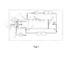
- FIG.1 is a schematic diagram showing the construction and principle of an ion migration spectrometer according to one specific embodiment of the present invention.
- an ion migration spectrometer 1 according to the present invention comprises: a migration pipe 4, for performing a ionization and migration operation on the sample to be detected that is introduced therein; and a sampling device 2, which has a sampling port for introducing the sample to be detected, wherein the sample to be detected may be introduced into the migration pipe 4 by sucking an air sample containing the gas atmosphere of the object to be detected or by inserting a sampling carrier which has collected the solid particle sample.
- the sampling device 2 is configured with a permselective semipermeable membrane 3 at the location near an inlet 41 of the migration pipe 4, for isolating the inside of the ion migration spectrometer from the sampling device 2 that is connected with the external environment.
- the ion migration spectrometer further comprises a sampling pump 10, for supplying negative pressure to introduce the gas sample to be detected into the sampling device 2.
- a sampling pump 10 for supplying negative pressure to introduce the gas sample to be detected into the sampling device 2.
- the molecules of a gaseous material to be detected that is introduced by the sampling device 2 in solid particle or gas sampling mode is brought in front of the semipermeable membrane 3 by an air flow; after being screened by the semipermeable membrane 3, the molecules enter the core element of the ion migration spectrometer 1, that is, an ion migration pipe 4, while the components that cannot permeate the semipermeable membrane 3 are evacuated under the action of the sampling pump 10.
- the migration pipe 4 is divided into an ionization reaction zone 6 and a migration zone 7 by an ion gate 5 that can be opened periodically.
- the molecules of the sample to be detected are ionized in the ionization zone to form ion clusters, and an oriented migration and separation process is accomplished on the resulted ion clusters in the migration zone.
- a voltage is applied on a cyclic electrode plate 8 to supply an electric field that is uniformly distributed.
- the molecules of the object to be detected are ionized and ion clusters are formed, and when the ion gate 5 is opened, the ion clusters enter the migration zone 7 under the action of the electric field and continue to migrate forward under the action of the electric field.
- the migration speed of the ion clusters are related to such factors as their mass, charge number and volume, etc., thus the times at which different ion clusters arrive at the detector 9 located at the end of the migration zone are different. Therefore, the type of material may be determined by detecting the feeble pulse current from the detector and the arrival time thereof and matching them with the standard material data base.
- the ion migration spectrometer 1 comprises: a gas path device, for supplying a carrier gas to the ionization zone and supplying a migration gas to the migration zone.
- the direction of the migration gas flow introduced from the back end of the instrument is opposite to the moving direction of the ions, the migration gas flow is led out from a location near the ion gate 5 in the ionization chamber; and under the propelling of a recycle gas pump 11, a part of the gas that is purified and dried by a filter 12 serves as migration gas flow S1 and enters the rear part of the migration zone, while the other part, that is, gas flow S2, forms a carrier gas flow via a gas path containing a dopant source 13 and enters the ionization reaction zone 6.
- Fig.2 shows a sampling device 2 for an ion migration spectrometer, which is adapted to introduce a sample to be detected into an inlet 41 of a migration pipe 4 of an ion migration spectrometer 1, comprising: an inner sleeve part 21, inside of which an inner cavity 23 is defined, wherein one end of the inner sleeve part 21 is connected with the inlet 41 of the migration pipe 4 via an inner-layer channel 24, and the other end of the inner sleeve part 21 is configured with an inner end cap 25 having an inner opening 31; and an outer sleeve part 22, which is configured as an eccentric sleeve that is coaxial with the inner sleeve part 21 and able to rotate with respect to the inner sleeve part 21, so as to form a sleeve cavity 26 between the inner sleeve part 21 and the outer sleeve part 22, wherein one end of the outer sleeve part 22 is configured with at least one connecting opening 27 that is selectively connected with the inner
- a heating part 29 is configured outside the inner sleeve part 21, for heating the inner cavity 23 to form a thermal resolving cavity, in which a solid sample to be detected is heated to form a gaseous sample to be detected.
- a flat sampling device made of a metallic material such as stainless steel, outside which a heating wire is winded to form a thermal resolving cavity.
- the sampling device is kept at a high temperature by means of continuously heating, so that the solid sample particles collected on the sampling carrier are heated to be resolved or gasified.
- the inner-layer channel 24 is configured inside the inner sleeve part 21, wherein under the action of the sampling pump 10, the inner-layer channel 24 introduces an air flow from the sampling device 2 into the inside of the ion migration spectrometer 1.
- a heat insulating layer 30 is further configured outside the heating part to form a heat insulation between the inner cavity 23 and the sleeve cavity 26.
- the sampling device is divided into an inner layer and an outer layer with different temperature, wherein the inner layer is the inner cavity 23 surrounded by the inner sleeve part 21, and it is connected with the branch channel 24a; the outer layer is the sleeve cavity 26 which is consisted of the inner sleeve part 21 and the outer sleeve part 22 that is coaxial with the inner sleeve part 21, and it is selectively connected with the branch channel 24b via the connecting opening 27.
- a mechanism that may control or change the entering of a gas sample into the inner-layer channel 24 is formed.
- a typical example is as shown in Fig.2 : the inner opening 31 is configured on one side near the location of the center on the inner end cap 25.
- the outer sleeve part is in the form of an eccentric sleeve that is coaxial with the inner sleeve, and correspondingly, the end cap thereof is in the form of an eccentric circle, of which the outer end cap 28 has several asymmetric openings, wherein the first outer opening 32 is configured in a location adjacent to the center, and it has a shape that is completely coincident with the inner-layer sampling device, each of the rest apertures 33 is distributed at a peripheral location and is connected with the sleeve cavity 26, and a plurality of connecting openings 27 selectively connected with the inner-layer channel 24 are also configured in the sleeve cavity, the locations of the first opening, the second opening and the connecting opening 27 at the end thereof may be changed by rotating the outer sleeve part.
- the first outer opening 32 is configured on one side near the location of the center on the outer end cap 28, and the shape is completely coincident with the inner-layer sampling device; while the second outer opening 33, for example, a plurality of circular apertures, are distributed on the peripheral locations, for example, the second outer opening 33 is configured on the other side far from the center and opposite to the first opening 32 on the outer end cap 28, and it is connected with the sleeve cavity 26.
- the inner opening and the first outer opening are rectangular aperture and the second outer opening 33 comprises a plurality of circular apertures
- the present invention is not limited hereto, for example, it may employ any suitable shapes.
- the outer end cap 28 when the outer end cap 28 is configured in the first location with respect to the inner end cap 25 in Fig.2A to perform solid particles sampling, the first outer opening 32 adjacent to the center of the outer end cap 28 is rotated to a location that is completely coincident with the inner opening 31 on the inner end cap 25, the first outer opening 32 on the outer end cap 28 is connected with the inner opening 31 on the inner end cap 25, the connecting opening 27 is not connected with the eccentric sleeve cavity 26, and the sample to be detected is introduced into the inner-layer channel 24 via the inner cavity 23; when the outer end cap 28 is configured in a second location with respect to the inner end cap 25 in Fig.2B to perform gas sampling, the outer sleeve part may be rotated so that the first outer opening 32 adjacent to the center is rotated to the side that is opposite to the location on the inner end cap 25, the first outer opening 32 on the outer end cap 28 is not connected with the inner opening 31 on the inner end cap 25, and at this point the eccentric sleeve cavity 26 and the
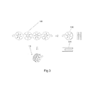
- An enrichment carrier 14 is configured in a location between the inner-layer channel 24 and the semipermeable membrane 3 and near the semipermeable membrane 3, for preconcentrating the material that is introduced into the migration pipe.
- the enrichment carrier 14 is consisted of a plurality of enrichment slices 140 laminated on each other, wherein each of the plurality of enrichment slices 140 comprises: a main body 141, which is consisted of a metallic film with micropores on the surface thereof or a mesh screen; and an adsorbent, which is attached to the surface of the main body 141, for absorbing the material to be detected.
- the mental concerned is generally stainless steel, and an adsorbing material, for example, active carbon powder and so on, is attached to the carrier, or an adsorbent that can absorb the object to be detected is coated on the carrier.
- an adsorbing material for example, active carbon powder and so on
- the enrichment carrier may be folded into the shape of waves; moreover, the micropores configured on the surface of each layer of carrier are arranged to interleave with each other, thus when gas passes through the carrier layer vertically, it may flow along the areas between the apertures on the carrier surface, so that the contact area between the sample gas flow and the adsorbent on the carrier collecting surface is increased.
- the device further comprises a pulse heating device (not shown) connected with the enrichment carrier 14, by which controllable pulse heating may be conducted on the enrichment carrier 14.
- a heating part 29 configured outside the inner sleeve part is started, for continuously heating the inner cavity 23 during the operation process to form a thermal resolving cavity.
- the outer end cap 28 is rotated so as to be configured in a first location shown in Fig.2A with respect to the inner end cap; the solid sample to be detected is introduced into a thermal resolving cavity that is formed via the first outer opening 32 on the outer end cap 28 and the inner opening 31 on the inner end cap 25, and in the thermal resolving cavity, the solid sample to be detected is heated to form a gaseous sample to be detected; and the gaseous sample to be detected is introduced into the inlet 41 of the migration pipe 4 via the inner-layer channel 24.
- the outer end cap 28 When gas sampling is performed, as shown in Fig.2B , the outer end cap 28 is rotated so as to be configured in a second location shown in Fig.2B with respect to the inner end cap 25; a gas sample to be detected is introduced into the inner-layer channel 24 via the second outer opening 32 on the outer end cap 28 and the sleeve cavity 26, and it is preconcentrated on the enrichment carrier 14; after the gas sample to be detected is preconcentrated on the enrichment carrier 14 for a predetermined time, the outer end cap 28 is rotated so as to be configured in the first location shown in Fig.2A with respect to the inner end cap 25; the gas flow is introduced onto the enrichment carrier 14 via thermal resolving cavity, and the pulse heating device connected to the enrichment carrier is selectively activated to gasify and resolve the sample to be detected that is preconcentrated on the enrichment carrier 14; and the gaseous sample to be detected is introduced into the inlet 41 of the migration pipe 4 via the inner-layer channel 24.
- thermal resolving cavity 23 of the sampling device of the ion migration spectrometer 1 is always in a continuously heating state, and when solid sampling is performed, the outer sleeve part 22 of the sampling device 2 is rotated to the first location shown in Fig.2A , so that the opening 32 on its end, which is adjacent to the center, is connected with the inner opening 31 on the inner end cap 25, while its connecting opening 27 is not connected with the sleeve cavity 26, and the gas enters the inside of the ion migration spectrometer 1 via thermal resolving cavity 23.
- a solid sampling carrier is inserted into the sampling device 2 via the above inner opening 31 and outer opening 32, and the solid particle sample collected by the carrier is gasified and enters the ion migration spectrometer 1 along with the air flow for analyzing.
- the outer sleeve part 22 is first rotated to the second location shown in Fig.2B , so that the opening 32 on its outer end cap 28, which is near the center, is rotated to the side opposite to the inner opening 31 on the inner end cap 25, while its connecting opening 27 is connected with the sleeve cavity 26, and the gas enters the inner-layer channel 24 via the sleeve cavity 26.
- the temperature of the gas introduced into the inner-layer channel 24 via the sleeve cavity 26 is close to the ambient temperature, and the temperature is still low when it passes through the enrichment carrier 14, which is favourable for the effective absorbing of the gas sample; after the gas sample is collected for a certain period of time, the outer sleeve part 22 is rotated to the first location shown in Fig.2A , that is, the location corresponding to the location of solid particles sampling ; at this point, the gas enters the ion migration spectrometer 1 from thermal resolving cavity 23 under the action of the sampling pump 10.
- the temperature of the gas flow will be increased quickly.
- the enrichment carrier 14 made of metallic material will be heated, and at the same time, the pulse heating function of the enrichment carrier 14 may also be activated, so that the temperature of the carrier will be increased rapidly, thereby releasing the material to be detected that is absorbed.
- the air resistance in the gas flow path is low during gas collection, flow rate of gas is large in the sample collection or absorption process, thus more gas atmosphere of the object to be detected may be sucked in; however, because the gas path is narrow and the flow rate of gas is small during the desorbing process, the component absorbed is released into the gas flow which has a small flow rate, so that the concentration effect may be enhanced.
- the enrichment carrier 14 is configured in a location that is near the semipermeable membrane 3, the object to be detected that is released during the desorbing process can quickly reach the surface of the semipermeable membrane 3, and a selective permeation process is thus accomplished. Thereby, sample loss in the gas flow channel due to absorption or condensation and deposition can be avoided, and the sensitivity of the ion migration spectrometer 1 can be further improved.
Landscapes
- Chemical & Material Sciences (AREA)
- Physics & Mathematics (AREA)
- Life Sciences & Earth Sciences (AREA)
- Chemical Kinetics & Catalysis (AREA)
- Electrochemistry (AREA)
- Health & Medical Sciences (AREA)
- Spectroscopy & Molecular Physics (AREA)
- Analytical Chemistry (AREA)
- Biochemistry (AREA)
- General Health & Medical Sciences (AREA)
- General Physics & Mathematics (AREA)
- Immunology (AREA)
- Pathology (AREA)
- Sampling And Sample Adjustment (AREA)
- Other Investigation Or Analysis Of Materials By Electrical Means (AREA)
Abstract
Description
- The present invention relates to the field of ion migration detection technologies, and in particular, to a sampling device for an ion migration spectrometer and a method for detecting samples to be detected of solid particles and gas by using said sampling device. Moreover, the invention further relates to an ion migration spectrometer provided with the above sampling device.
- A detecting instrument based on ion migration spectrum (IMS) technologies may be used for detecting trace-level prohibited articles such as explosives, drugs and toxic chemicals, etc.. Due to the characteristics of quick speed, sensitiveness and portability, etc., such detecting instrument has now been widely used in military and safety inspection fields. Most of the commercialized portable IMS instruments adopt two sampling methods, that is, solid sampling or wiping sampling, and gas sampling. The former collects particles to be detected by wiping the surface of a suspicious object with a clean sampling carrier, for example, wipe paper, then puts the wipe paper or the sampling carrier adhering with the sample particles to the instrument inlet, and gasifies the solid explosives for analyzing through the method of thermal desorption. During the sampling and testing processes, the operator needs to wear gloves or to use a customized wiping sampler furnished with a sampling carrier in order to avoid polluting the sampling carrier and the detecting instrument. The latter sucks the gas atmosphere or the vaporous sample on the solid surface, which is to be detected, into the sampling device of the instrument for analyzing, via a suction pump directly.
- The gas sampling method is easy to operate, no consumable is needed, and it may avoid to directly contacting the object to be detected. However, because the vapor pressure of most objects to be detected, for example, explosives and drugs, is very low (below ppb), it is difficult to reach the lower limit of detection of an instrument simply by the collecting mode of sucking a sample directly. If a preconcentration or preenrichment device is configured on the front end of an analyzing system, the detection capability of the instrument may be improved greatly. A preconcentrator mainly comprises an adsorbing material and a heater, and its operational principle lies in that the gas to be detected is first passed through the adsorbing material for enrichment, and after a certain period of time, the gas absorbed is resolved in a short time by heating the adsorbing material, so that a higher gas concentration may be obtained. Some commercialized instruments, for example, VaporTracer from GE, employ an external portable vacuum suction device for collecting gas samples, wherein a sampling carrier is first placed in the suction port of the vacuum device, and molecules of an object to be detected are captured thereon after an air containing the vapor of the object to be detected is passed through the sampling carrier for a certain period of time, then the sampling medium is placed into the detector and the molecules of the object to be detected are released for analyzing via the method of thermal desorption; therefore, the device actually plays a role of sample enrichment.
- At present, there are a plurality of related patents that respectively describe a preconcentration device for an ion migration spectrometer or other analyzing instrument of the same type. Patent
US5162652 describes a technology of sample mixing, concentrating and introducing, in which a part of the gas in a sealed luggage is extracted and combined with the ambient atmosphere in a closed cavity, the mixed sample is passed through a collector, and certain molecules to be detected are aggregated onto a collecting surface for concentration, then the molecules absorbed are released from the surface and sent to an ion migration spectrometer for analyzing. PatentUS6604406 describes a preconcentration device that can be manually carried, in which an object is captured via a permeable mesh screen, and then the materials of the object are released into a cavity by heating. PatentUS5083019 describes an absorbing probe concentration device, in which an absorbing probe made of a metallic filament coil having an absorbing coating is placed in a sampling gas flow at a low temperature, the gas sample is collected via its surface, and during the testing process, the probe is manually fed into a ionization reaction zone of the ion migration device via a slide shaft and then heated rapidly, so that the material to be detected is resolved and ionized. Patent applicationW02007091998 describes a concentration technology of solid phase micro-extracting optical fiber collection, in which a solid phase micro-extracting optical fiber exposed in air is employed to collect a sample of explosives, taggants or a mixture thereof, and after thermal desorption, the optical fiber is put into a preconcentration device for concentrating the sample, and then the sample is fed into an ion migration spectrometer for detecting. PatentUS20090249958 describes a device component that may replace the concentration carrier, wherein the device component is consisted of a housing and an inner rack, and a cavity that may accommodate several concentration carriers and a channel that accesses to a sampling device of a detecting instrument are formed via a retractable spring compressing device, thus the material collected by the concentration carrier may be brought into the instrument for analyzing via a consecutive gas flow. The concentration device disclosed in patent applicationW02008074981 is located inside the ion migration sampling device, a small negative pressure and a small positive pressure are alternately applied to the pipe cavity via a pulse pressure generator connected with the migration pipe cavity, so that an air is sucked into or evacuated from the sampling device in a mode that emulates gasping, thus the component to be detected is effectively absorbed by the preconcentration device, instead of entering the ionization zone, and after the component to be detected is accumulated for a certain period of time, the pressure generator generates a larger negative pressure, so that the object to be detected that is released by the preconcentration device is sucked into the ionization zone inside the instrument for analyzing. The preconcentration device described in patent applicationW02007113486 is connected with the inlet of an ion migration spectrometer, wherein the preconcentration device is formed by a metal pipe of which the inner surface has a layer of silastic adsorbing material, and a resistance heating element connected with a power is configured under the absorbing layer for periodically heating the silastic absorbing layer, so that the material absorbed is desorbed and released to an ion migration spectrometer at a higher concentration. - In practical application, because at present, solid wiping sampling is still the sample collecting mode commonly used by the ion migration instrument, a sampling carrier sampling device and a thermal resolver for heating the carrier are often configured on the front end of the instrument. In order not to influence the solid sampling device and the function of the instrument, the concentrator described in the above patents/patent applications (for example,
US5162652 ,US6604406 ,W02007091998 andUS20090249958 , etc.) generally employs an external design and needs a separate device that is independent of the instrument, and after sample collection is accomplished, sampling is performed in the same mode as solid sampling, thereby the process of the whole detecting operation is made boresome and complex; on the other hand, in an IMS instrument with a built-in concentrator (for example,W02008074981 andW02007113486 , etc.), because the absorbing element in the concentrator needs to work at a low temperature, no thermal resolver is configured on the front end of the instrument, thus the instrument can only be used for analyzing a gas sample. - Therefore, a more practical IMS instrument that has the functions of solid sampling and gas sampling simultaneously needs to be developed in the prior art. On one hand, it has a built-in concentration device, for simplifying instrument configuration and operation procedure; on the other hand, it may perform a sensitive and facile detection on a trace-amount solid residual and an extremely low concentration gas atmosphere of an object to be detected.
- Therefore, it is an object of the present invention to solve at least one aspect of the above problems and defects in the prior art.
- Accordingly, directed to the shortages in the design of the above existing ion migration spectrum trace-amount analyzing instrument that may detect a gas sample, it is one of the objects of the invention to put forward a design of a novel sampling device for an ion migration spectrometer, and a method for using the same, wherein a solid particle sample analyzing function and a low-concentration gas analyzing function are integrated in a single instrument, so that the functions of solid sampling and gas sampling can be achieved simultaneously by the same sampling device.
- A further object of the invention is to provide a design of a novel sampling device for an ion migration spectrometer and a method for using the same, wherein no additional gas sample collection and concentration device is needed, moreover, not only the operation procedure can be simplified and the sensitivity and analyzing efficiency on the gas sample can be improved, but also an effective detection on a trace-amount of a solid sample may be realized at the same time.
- According to one aspect of the present invention, it provides a sampling device for an ion migration spectrometer, which is adapted to introduce a sample to be detected into an inlet of a migration pipe of the ion migration spectrometer, wherein the sampling device comprises: an inner sleeve part, inside of which an inner cavity is defined, wherein one end of the inner sleeve part is connected with the inlet of the migration pipe via an inner-layer channel, and the other end of the inner sleeve part is configured with an inner end cap having an inner opening; and an outer sleeve part, which is configured as an eccentric sleeve that is coaxial with the inner sleeve part and able to rotate with respect to the inner sleeve part, so as to form a sleeve cavity between the inner sleeve part and the outer sleeve part, wherein at least one connecting opening selectively connected with the inner-layer channel is configured at one end of the outer sleeve part, and an outer end cap, on which a first outer opening selectively connected with the inner opening and a second outer opening selectively connected with the sleeve cavity are configured, is configured at the other end of the outer sleeve part, wherein the outer end cap is configured to be able to rotate between a first location and a second location with respect to the inner end cap, so as to selectively introduce a sample to be detected into the inner-layer channel via one of the inner cavity and the sleeve cavity.
- In the above embodiment, when the outer end cap is configured to be located in the first location with respect to the inner end cap, the first outer opening on the outer end cap is connected with the inner opening on the inner end cap, the connecting opening is not connected with the inner-layer channel, and the sample to be detected is introduced into the inner-layer channel via the inner cavity; when the outer end cap is configured to be located in the second location with respect to the inner end cap, the first outer opening on the outer end cap is not connected with the inner opening on the inner end cap, the second outer opening on the outer end cap is connected with the sleeve cavity, the connecting opening is connected with the inner-layer channel, and the sample to be detected is introduced into the inner-layer channel via the sleeve cavity.
- Preferably, a heating part is configured outside the inner sleeve part, for heating the inner cavity to form a thermal resolving cavity, in which a solid sample to be detected is heated to form a gaseous sample to be detected.
- Preferably, a heat insulating layer is further configured outside the heating part, so that heat insulation may be accomplished between the inner sleeve part and the outer sleeve part.
- Specifically, the inner opening is configured on one side near the location of the center on the inner end cap; the first outer opening is configured on one side near the location of the center on the outer end cap, and the second outer opening is configured on the other side far from the center and opposite to the first opening on the outer end cap.
- More specifically, the inner opening and the first outer opening are rectangular apertures, and the second outer opening comprises a plurality of circular apertures.
- In one embodiment, the sampling device for an ion migration spectrometer further comprises: a semipermeable membrane, which is configured between the inlet of the migration pipe and the inner-layer channel, for selectively permeating of a gaseous material to be detected that is introduced into the migration pipe.
- Moreover, the sampling device for an ion migration spectrometer further comprises: an enrichment carrier, which is configured between the semipermeable membrane and the inner-layer channel and is adjacent to the location of the semipermeable membrane, for preconcentrating the material to be detected that enters the inner-layer channel.
- Specifically, the enrichment carrier is consisted of a plurality of enrichment slices laminated on each other, each of the plurality of enrichment slices comprises: a main body, which is consisted of a metallic film with micropores on the surface thereof or a mesh screen; and an adsorbent, which is attached to the surface of the main body to absorb the material to be detected.
- More specifically, the micropores in the plurality of enrichment slices laminated on each other are arranged to interleave with each other, so that when a gas passes through the enrichment carrier vertically, the contact area between the sample gas flow and the adsorbent in the enrichment slices may be increased.
- More specifically, the device further comprises: a pulse heating device, which is connected with the enrichment carrier, for performing controllable pulse heating on the enrichment carrier.
- According to another aspect of the present invention, it provides a method for introducing a solid sample to be detected by using the above sampling device for an ion migration spectrometer, comprising the steps of: starting the heating part configured outside the inner sleeve part, for continuously heating the inner cavity during the operation process to form a thermal resolving cavity; rotating the outer end cap so as to configure the outer end cap to be located in the first location with respect to the inner end cap; introducing the solid sample to be detected into thermal resolving cavity via the first outer opening on the outer end cap and the inner opening on the inner end cap, wherein in the thermal resolving cavity, the solid sample to be detected is heated to form a gaseous sample to be detected; and introducing the gaseous sample to be detected into the inlet of the migration pipe via the inner-layer channel.
- According to a further aspect of the present invention, it provides a method for introducing a gas sample to be detected by using the above sampling device for an ion migration spectrometer, comprising the steps of: starting the heating part configured outside the inner sleeve part, for continuously heating the inner cavity during the operation process to form a thermal resolving cavity; rotating the outer end cap so as to configure the outer end cap to be located in the second location with respect to the inner end cap; introducing a gas sample to be detected into the inner-layer channel via the second outer opening on the outer end cap and the sleeve cavity, and performing preconcentration on the enrichment carrier; rotating the outer end cap after preconcentrating the gas sample to be detected on the enrichment carrier for predetermined time, so as to configure the outer end cap to be located in the first location with respect to the inner end cap; introducing the gas flow to the enrichment carrier via the thermal resolving cavity and activating the pulse heating device connected to the enrichment carrier at the same time, so that the sample to be detected that is preconcentrated on the enrichment carrier is resolved, thereby forming a gaseous sample to be detected; and introducing the gaseous sample to be detected into the inlet of the migration pipe.
- According to a further aspect of the present invention, it provides an ion migration spectrometer comprising: a migration pipe, for performing a ionization and migration operation on a sample to be detected that is introduced therein; a gas path device, for supplying carrier gas to the ionization zone and supplying migration gas to the migration zone; and a sampling device as described above, for introducing the sample to be detected into the inlet of the migration pipe.
- In the above technical solutions, the ion migration spectrometer further comprises: a sampling pump, for supplying negative pressure to introduce the gas sample to be detected into the sampling device.
- Specifically, the migration pipe comprises: an ionization zone, in which molecules of the sample to be detected are ionized to form an ion cluster; and a migration zone, in which an oriented migration and separation process is performed on the ion cluster.
- The above unspecified embodiments of the present invention at least have the advantages and effects of the following one or more aspects:
- 1) The switch of two different locations can be performed between the inner and outer sleeves by employing a structure design of inner and outer sleeves, so that two different gas flow paths are provided selectively. With the above solution, a solid particle sample analyzing function and a low-concentration gas analyzing function are integrated in a single instrument, so that the functions of solid sampling and gas sampling can be compromised by the same sampling device.
- 2) Moreover, in one embodiment of the present invention, no external gas sample collection and concentration device needs to be equipped, and not only the operation procedure can be simplified and the sensitivity and analyzing efficiency on the gas sample can be improved, but also an effective detection on a trace-amount of a solid sample may be realized at the same time. Specifically, in one embodiment of the invention, the enrichment carrier is configured in a location adjacent to the semipermeable membrane in the sampling device, and the sampling end employs a unique sleeve-type structure design with a rotatable end cap, in the case that the solid sampling function of the instrument is not influenced, by means of controlling the channel that the gas enters and making the best of the heat source of the solid sampling device, low temperature absorption and quick warming up desorption of the gas sample by the enrichment carrier can be realized, so that effective preconcentration may be accomplished, and the instrument is made to have both trace-amount solid particle sample analyzing function and extremely low concentration gas sample analyzing function, without the need for additionally equipping a separate gas collection and concentration device, thereby simplifying the configuration and operation procedure of the instrument and greatly improving the analyzing efficiency of the instrument on gas sample.
- 3) Moreover, in the present invention, the enrichment carrier is configured in a location adjacent to the semipermeable membrane in the sampling device, the object to be detected that is released during the desorbing process can reach the membrane surface quickly, and a selective permeation process is thus accomplished, so that sample loss in the gas flow channel due to absorption or condensation and deposition can be avoided, and the sensitivity of the instrument can be further improved.
-
-
Fig.1 is a schematic diagram showing the construction and principle of an ion migration spectrometer according to one specific embodiment of the present invention; -
Fig.2 is a schematic diagram showing the structure of a sampling device for an ion migration spectrometer according to one specific embodiment of the present invention, in whichFig.2A is a schematic diagram showing the introduction of a solid particle sample into the sampling device, andFig.2B is a schematic diagram showing the introduction of a gas sample into the sampling device; and -
Fig.3 is a schematic diagram showing an enrichment carrier for an ion migration spectrometer according to one embodiment of the present invention. - The technical solutions of the present invention will now be further illustrated in detail by specific embodiments in conjunction with
Figs.1-3 . In the specification, the same or similar reference number indicates the same or similar part. The following illustrations on the embodiments of the invention referring to the drawings are to explain the general inventive concept of the present invention, and it should not be construed as limiting the scope of the invention. -
Fig.1 is a schematic diagram showing the construction and principle of an ion migration spectrometer according to one specific embodiment of the present invention. As shown inFig.1 , an ion migration spectrometer 1 according to the present invention comprises: a migration pipe 4, for performing a ionization and migration operation on the sample to be detected that is introduced therein; and a sampling device 2, which has a sampling port for introducing the sample to be detected, wherein the sample to be detected may be introduced into the migration pipe 4 by sucking an air sample containing the gas atmosphere of the object to be detected or by inserting a sampling carrier which has collected the solid particle sample. The sampling device 2 is configured with a permselective semipermeable membrane 3 at the location near an inlet 41 of the migration pipe 4, for isolating the inside of the ion migration spectrometer from the sampling device 2 that is connected with the external environment. - Referring to
Fig.1 , the ion migration spectrometer further comprises a sampling pump 10, for supplying negative pressure to introduce the gas sample to be detected into the sampling device 2. Under the action of the sampling pump 10, the molecules of a gaseous material to be detected that is introduced by the sampling device 2 in solid particle or gas sampling mode is brought in front of the semipermeable membrane 3 by an air flow; after being screened by the semipermeable membrane 3, the molecules enter the core element of the ion migration spectrometer 1, that is, an ion migration pipe 4, while the components that cannot permeate the semipermeable membrane 3 are evacuated under the action of the sampling pump 10. - The migration pipe 4 is divided into an ionization reaction zone 6 and a migration zone 7 by an ion gate 5 that can be opened periodically. The molecules of the sample to be detected are ionized in the ionization zone to form ion clusters, and an oriented migration and separation process is accomplished on the resulted ion clusters in the migration zone. In the migration zone 7, a voltage is applied on a cyclic electrode plate 8 to supply an electric field that is uniformly distributed. In the ionization zone 5 of the ion migration pipe 4, the molecules of the object to be detected are ionized and ion clusters are formed, and when the ion gate 5 is opened, the ion clusters enter the migration zone 7 under the action of the electric field and continue to migrate forward under the action of the electric field. In the migration zone 7, the migration speed of the ion clusters are related to such factors as their mass, charge number and volume, etc., thus the times at which different ion clusters arrive at the detector 9 located at the end of the migration zone are different. Therefore, the type of material may be determined by detecting the feeble pulse current from the detector and the arrival time thereof and matching them with the standard material data base.
- Moreover, the ion migration spectrometer 1 comprises: a gas path device, for supplying a carrier gas to the ionization zone and supplying a migration gas to the migration zone. The direction of the migration gas flow introduced from the back end of the instrument is opposite to the moving direction of the ions, the migration gas flow is led out from a location near the ion gate 5 in the ionization chamber; and under the propelling of a recycle gas pump 11, a part of the gas that is purified and dried by a
filter 12 serves as migration gas flow S1 and enters the rear part of the migration zone, while the other part, that is, gas flow S2, forms a carrier gas flow via a gas path containing a dopant source 13 and enters the ionization reaction zone 6. - The structure and principle of the sampling device for an ion migration spectrometer according to one specific embodiment of the present invention will now be illustrated briefly in conjunction with
Fig.2A-2B . -
Fig.2 shows a sampling device 2 for an ion migration spectrometer, which is adapted to introduce a sample to be detected into an inlet 41 of a migration pipe 4 of an ion migration spectrometer 1, comprising: an inner sleeve part 21, inside of which an inner cavity 23 is defined, wherein one end of the inner sleeve part 21 is connected with the inlet 41 of the migration pipe 4 via an inner-layer channel 24, and the other end of the inner sleeve part 21 is configured with an inner end cap 25 having an inner opening 31; and an outer sleeve part 22, which is configured as an eccentric sleeve that is coaxial with the inner sleeve part 21 and able to rotate with respect to the inner sleeve part 21, so as to form a sleeve cavity 26 between the inner sleeve part 21 and the outer sleeve part 22, wherein one end of the outer sleeve part 22 is configured with at least one connecting opening 27 that is selectively connected with the inner-layer channel 24, and the other end of the outer sleeve part 22 is configured with an outer end cap 28, on which a first outer opening 32 that is selectively connected with the inner opening 31 and a second outer opening 33 that is selectively connected with the sleeve cavity 26 are configured, wherein the outer end cap 28 is configured to be able to rotate between a first location (the location as shown inFig.2A ) and a second location (the location as shown inFig.2B ) with respect to the inner end cap 25, so as to selectively introduce a sample to be detected into the inner-layer channel 24 via one of the inner cavity 23 and the sleeve cavity 26. As shown inFig.2 , the inner-layer channel 24 comprises: a branch channel 24a, which is connected with theinner cavity 23; and a branch channel 24b, which is connected with the sleeve cavity 26 via the connecting opening 27. - Referring to
Fig.2 , aheating part 29 is configured outside theinner sleeve part 21, for heating theinner cavity 23 to form a thermal resolving cavity, in which a solid sample to be detected is heated to form a gaseous sample to be detected. One common example is a flat sampling device made of a metallic material such as stainless steel, outside which a heating wire is winded to form a thermal resolving cavity. The sampling device is kept at a high temperature by means of continuously heating, so that the solid sample particles collected on the sampling carrier are heated to be resolved or gasified. The inner-layer channel 24 is configured inside theinner sleeve part 21, wherein under the action of the sampling pump 10, the inner-layer channel 24 introduces an air flow from the sampling device 2 into the inside of the ion migration spectrometer 1. - In the above embodiment, a
heat insulating layer 30 is further configured outside the heating part to form a heat insulation between theinner cavity 23 and the sleeve cavity 26. Thus, the sampling device is divided into an inner layer and an outer layer with different temperature, wherein the inner layer is theinner cavity 23 surrounded by theinner sleeve part 21, and it is connected with the branch channel 24a; the outer layer is the sleeve cavity 26 which is consisted of theinner sleeve part 21 and theouter sleeve part 22 that is coaxial with theinner sleeve part 21, and it is selectively connected with the branch channel 24b via the connecting opening 27. - In the above embodiment of the present invention, a mechanism that may control or change the entering of a gas sample into the inner-layer channel 24 is formed. A typical example is as shown in
Fig.2 : the inner opening 31 is configured on one side near the location of the center on theinner end cap 25. The outer sleeve part is in the form of an eccentric sleeve that is coaxial with the inner sleeve, and correspondingly, the end cap thereof is in the form of an eccentric circle, of which theouter end cap 28 has several asymmetric openings, wherein the firstouter opening 32 is configured in a location adjacent to the center, and it has a shape that is completely coincident with the inner-layer sampling device, each of the rest apertures 33 is distributed at a peripheral location and is connected with the sleeve cavity 26, and a plurality of connecting openings 27 selectively connected with the inner-layer channel 24 are also configured in the sleeve cavity, the locations of the first opening, the second opening and the connecting opening 27 at the end thereof may be changed by rotating the outer sleeve part. Referring toFig.2 , the firstouter opening 32 is configured on one side near the location of the center on theouter end cap 28, and the shape is completely coincident with the inner-layer sampling device; while the second outer opening 33, for example, a plurality of circular apertures, are distributed on the peripheral locations, for example, the second outer opening 33 is configured on the other side far from the center and opposite to thefirst opening 32 on theouter end cap 28, and it is connected with the sleeve cavity 26. Although inFig.2 the inner opening and the first outer opening are rectangular aperture and the second outer opening 33 comprises a plurality of circular apertures, the present invention is not limited hereto, for example, it may employ any suitable shapes. - Referring to
Fig.2 , when the outer end cap 28 is configured in the first location with respect to the inner end cap 25 inFig.2A to perform solid particles sampling, the first outer opening 32 adjacent to the center of the outer end cap 28 is rotated to a location that is completely coincident with the inner opening 31 on the inner end cap 25, the first outer opening 32 on the outer end cap 28 is connected with the inner opening 31 on the inner end cap 25, the connecting opening 27 is not connected with the eccentric sleeve cavity 26, and the sample to be detected is introduced into the inner-layer channel 24 via the inner cavity 23; when the outer end cap 28 is configured in a second location with respect to the inner end cap 25 inFig.2B to perform gas sampling, the outer sleeve part may be rotated so that the first outer opening 32 adjacent to the center is rotated to the side that is opposite to the location on the inner end cap 25, the first outer opening 32 on the outer end cap 28 is not connected with the inner opening 31 on the inner end cap 25, and at this point the eccentric sleeve cavity 26 and the inner-layer channel 24 are connected via a plurality of openings 27, thus the gas may enter the inner-layer channel 24 via the sleeve cavity 26. - The rotation of inner and
outer end caps enrichment carrier 14 is configured in a location between the inner-layer channel 24 and the semipermeable membrane 3 and near the semipermeable membrane 3, for preconcentrating the material that is introduced into the migration pipe. Specifically, referring toFig.3 , theenrichment carrier 14 is consisted of a plurality of enrichment slices 140 laminated on each other, wherein each of the plurality of enrichment slices 140 comprises: a main body 141, which is consisted of a metallic film with micropores on the surface thereof or a mesh screen; and an adsorbent, which is attached to the surface of the main body 141, for absorbing the material to be detected. The mental concerned is generally stainless steel, and an adsorbing material, for example, active carbon powder and so on, is attached to the carrier, or an adsorbent that can absorb the object to be detected is coated on the carrier. Different designs may be employed to make the enrichment carrier have a larger absorbing area, for example, the enrichment carrier may be folded into the shape of waves; moreover, the micropores configured on the surface of each layer of carrier are arranged to interleave with each other, thus when gas passes through the carrier layer vertically, it may flow along the areas between the apertures on the carrier surface, so that the contact area between the sample gas flow and the adsorbent on the carrier collecting surface is increased. In one embodiment, the device further comprises a pulse heating device (not shown) connected with theenrichment carrier 14, by which controllable pulse heating may be conducted on theenrichment carrier 14. - The specific operation of solid particle sampling and gas sampling by using the above sampling device will be illustrated bellow in conjunction with the drawings.
- Before the sampling operation, a
heating part 29 configured outside the inner sleeve part is started, for continuously heating theinner cavity 23 during the operation process to form a thermal resolving cavity. When solid particle sampling is performed, as shown inFig.2A , theouter end cap 28 is rotated so as to be configured in a first location shown inFig.2A with respect to the inner end cap; the solid sample to be detected is introduced into a thermal resolving cavity that is formed via the firstouter opening 32 on theouter end cap 28 and the inner opening 31 on theinner end cap 25, and in the thermal resolving cavity, the solid sample to be detected is heated to form a gaseous sample to be detected; and the gaseous sample to be detected is introduced into the inlet 41 of the migration pipe 4 via the inner-layer channel 24. - When gas sampling is performed, as shown in
Fig.2B , theouter end cap 28 is rotated so as to be configured in a second location shown inFig.2B with respect to theinner end cap 25; a gas sample to be detected is introduced into the inner-layer channel 24 via the second outer opening 32 on theouter end cap 28 and the sleeve cavity 26, and it is preconcentrated on theenrichment carrier 14; after the gas sample to be detected is preconcentrated on theenrichment carrier 14 for a predetermined time, theouter end cap 28 is rotated so as to be configured in the first location shown inFig.2A with respect to theinner end cap 25; the gas flow is introduced onto theenrichment carrier 14 via thermal resolving cavity, and the pulse heating device connected to the enrichment carrier is selectively activated to gasify and resolve the sample to be detected that is preconcentrated on theenrichment carrier 14; and the gaseous sample to be detected is introduced into the inlet 41 of the migration pipe 4 via the inner-layer channel 24. - In a practical detection process, thermal resolving
cavity 23 of the sampling device of the ion migration spectrometer 1 is always in a continuously heating state, and when solid sampling is performed, theouter sleeve part 22 of the sampling device 2 is rotated to the first location shown inFig.2A , so that theopening 32 on its end, which is adjacent to the center, is connected with the inner opening 31 on theinner end cap 25, while its connecting opening 27 is not connected with the sleeve cavity 26, and the gas enters the inside of the ion migration spectrometer 1 via thermal resolvingcavity 23. A solid sampling carrier is inserted into the sampling device 2 via the above inner opening 31 andouter opening 32, and the solid particle sample collected by the carrier is gasified and enters the ion migration spectrometer 1 along with the air flow for analyzing. - When gas sampling is performed by the ion migration spectrometer 1, the
outer sleeve part 22 is first rotated to the second location shown inFig.2B , so that theopening 32 on itsouter end cap 28, which is near the center, is rotated to the side opposite to the inner opening 31 on theinner end cap 25, while its connecting opening 27 is connected with the sleeve cavity 26, and the gas enters the inner-layer channel 24 via the sleeve cavity 26. Because a heat insulating layer exists between the sleeve cavity 26 and thermal resolvingcavity 23, the temperature of the gas introduced into the inner-layer channel 24 via the sleeve cavity 26 is close to the ambient temperature, and the temperature is still low when it passes through theenrichment carrier 14, which is favourable for the effective absorbing of the gas sample; after the gas sample is collected for a certain period of time, theouter sleeve part 22 is rotated to the first location shown inFig.2A , that is, the location corresponding to the location of solid particles sampling ; at this point, the gas enters the ion migration spectrometer 1 from thermal resolvingcavity 23 under the action of the sampling pump 10. - At this moment, because the gas flow passes through thermal resolving
cavity 23 that is at a high temperature, the temperature of the gas flow will be increased quickly. When the gas flow passes through theenrichment carrier 14, theenrichment carrier 14 made of metallic material will be heated, and at the same time, the pulse heating function of theenrichment carrier 14 may also be activated, so that the temperature of the carrier will be increased rapidly, thereby releasing the material to be detected that is absorbed. Because the air resistance in the gas flow path is low during gas collection, flow rate of gas is large in the sample collection or absorption process, thus more gas atmosphere of the object to be detected may be sucked in; however, because the gas path is narrow and the flow rate of gas is small during the desorbing process, the component absorbed is released into the gas flow which has a small flow rate, so that the concentration effect may be enhanced. Moreover, because theenrichment carrier 14 is configured in a location that is near the semipermeable membrane 3, the object to be detected that is released during the desorbing process can quickly reach the surface of the semipermeable membrane 3, and a selective permeation process is thus accomplished. Thereby, sample loss in the gas flow channel due to absorption or condensation and deposition can be avoided, and the sensitivity of the ion migration spectrometer 1 can be further improved. - Although some embodiments of the general inventive concept have been shown and illustrated, it will be understood by one skilled in the art that various modifications can be made to these embodiments without departing from the spirit or scope of the general inventive concept, and the scope of the invention will be defined by the claims and their equivalents.
Claims (17)
- A sampling device for an ion migration spectrometer, which is adapted to introduce a sample to be detected into an inlet of a migration pipe of the ion migration spectrometer, wherein the sampling device comprises:an inner sleeve part, inside of which an inner cavity is defined, one end of the inner sleeve part is connected with the inlet of the migration pipe via an inner-layer channel, and the other end of the inner sleeve part is configured with an inner end cap having an inner opening; andan outer sleeve part, which is configured as an eccentric sleeve that is coaxial with the inner sleeve part and able to rotate with respect to the inner sleeve part, so as to form a sleeve cavity between the inner sleeve part and the outer sleeve part, one end of the outer sleeve part is configured with at least one connecting opening that is selectively connected with the inner-layer channel, and the other end of the outer sleeve part is configured with an outer end cap, on which a first outer opening selectively connected with the inner opening and a second outer opening selectively connected with the sleeve cavity are configured,wherein, the outer end cap is configured to be able to rotate between a first location and a second location with respect to the inner end cap, so as to selectively introduce a sample to be detected into the inner-layer channel via one of the inner cavity and the sleeve cavity.
- The sampling device for an ion migration spectrometer according to claim 1, wherein:when the outer end cap is configured to be located in the first location with respect to the inner end cap, the first outer opening on the outer end cap is connected with the inner opening on the inner end cap, the connecting opening is not connected with the inner-layer channel, and the sample to be detected is introduced into the inner-layer channel via the inner cavity;when the outer end cap is configured to be located in the second location with respect to the inner end cap, the first outer opening on the outer end cap is not connected with the inner opening on the inner end cap, the second outer opening on the outer end cap is connected with the sleeve cavity, the connecting opening is connected with the inner-layer channel, and the sample to be detected is introduced into the inner-layer channel via the sleeve cavity.
- The sampling device for an ion migration spectrometer according to claim 1 or 2, wherein:a heating part is configured outside the inner sleeve part, for heating the inner cavity to form a thermal resolving cavity, in which a solid sample to be detected is heated to form a gaseous sample to be detected.
- The sampling device for an ion migration spectrometer according to claim 3, wherein:a heat insulating layer is further configured outside the heating part, for forming heat insulation between the inner sleeve part and the outer sleeve part.
- The sampling device for an ion migration spectrometer according to claim 3, wherein:the inner opening is configured on one side near the location of the center on the inner end cap; andthe first outer opening is configured on one side near the location of the center on the outer end cap, and the second outer opening is configured on the other side far from the center and opposite to the first opening on the outer end cap.
- The sampling device for an ion migration spectrometer according to claim 5, wherein:the inner opening and the first outer opening are rectangular apertures, and the second outer opening comprises a plurality of circular apertures.
- The sampling device for an ion migration spectrometer according to claim 4, further comprising:a semipermeable membrane, which is configured between the inlet of the migration pipe and the inner-layer channel, for filtering a gaseous material introduced into the migration pipe.
- The sampling device for an ion migration spectrometer according to claim 7, further comprising:an enrichment carrier, which is configured between the semipermeable membrane and the inner-layer channel and is adjacent to the location of the semipermeable membrane, for preconcentrating the material to be detected that enters the inner-layer channel.
- The sampling device for an ion migration spectrometer according to claim 8, wherein:the enrichment carrier is consisted of a plurality of enrichment slices laminated on each other, each of the plurality of enrichment slices comprises:a main body, which is consisted of a metallic film with micropores on the surface thereof; andan adsorbent, which is attached to the surface of the main body, for absorbing the material to be detected.
- The sampling device for an ion migration spectrometer according to claim 9, further comprising:a pulse heating device, which is connected to the enrichment carrier, for performing controllable pulse heating on the enrichment carrier.
- The sampling device for an ion migration spectrometer according to claim 9, wherein:the micropores in the plurality of enrichment slices laminated on each other are arranged to interleave with each other, so that when a gas passes through the enrichment carrier vertically, the contact area between the sample gas flow and the adsorbent in the enrichment slices is increased.
- A method for introducing a solid sample to be detected by using the sampling device for an ion migration spectrometer according to claim 3, comprising the steps of:starting the heating part configured outside the inner sleeve part, for continuously heating the inner cavity during the operation process to form a thermal resolving cavity;rotating the outer end cap, so as to configure the outer end cap to be located in the first location with respect to the inner end cap;introducing the solid sample to be detected into the thermal resolving cavity via the first outer opening on the outer end cap and the inner opening on the inner end cap, wherein in the thermal resolving cavity, the solid sample to be detected is heated to form a gaseous sample to be detected; andintroducing the gaseous sample to be detected into the inlet of the migration pipe via the inner-layer channel.
- A method for introducing a gas sample to be detected by using the sampling device for an ion migration spectrometer according to claim 8, comprising the steps of:starting the heating part configured outside the inner sleeve part, for continuously heating the inner cavity during an operation process to form a thermal resolving cavity;rotating the outer end cap, so as to configure the outer end cap to be located in the second location with respect to the inner end cap;introducing the gas sample to be detected into the inner-layer channel via the second outer opening on the outer end cap and the sleeve cavity, and performing preconcentration on the enrichment carrier;rotating the outer end cap after preconcentrating the gas sample to be detected on the enrichment carrier for a predetermined time, so as to configure the outer end cap to be located in the first location with respect to the inner end cap;introducing the gas flow to the enrichment carrier via the thermal resolving cavity, so as to resolve the sample to be detected that is preconcentrated on the enrichment carrier and form a gaseous sample to be detected; andintroducing the gaseous sample to be detected into the inlet of the migration pipe via the inner-layer channel.
- The method for introducing a gas sample to be detected by using the sampling device for an ion migration spectrometer according to claim 13, further comprising the steps of:starting the pulse heating device connected to the enrichment carrier, for performing controllable pulse heating on the enrichment carrier.
- An ion migration spectrometer, comprising:a migration pipe, for performing an ionization and migration operation on the sample to be detected that is introduced therein;a gas path device, for supplying a carrier gas to an ionization zone and supplying a migration gas to a migration zone; andthe sampling device according to claims 1-10, for introducing the sample to be detected into the inlet of the migration pipe.
- The ion migration spectrometer according to claim 15, further comprising:a sampling pump, for supplying negative pressure to introduce the gas sample to be detected into the sampling device.
- The ion migration spectrometer according to claim 15, wherein, the migration pipe comprises:the ionization zone, in which molecules of the sample to be detected are ionized to form an ion cluster; andthe migration zone, in which an oriented migration and separation process is performed on the ion cluster.
Priority Applications (1)
| Application Number | Priority Date | Filing Date | Title |
|---|---|---|---|
| PL11726316T PL2492677T3 (en) | 2010-12-31 | 2011-05-04 | Sample introducing device for ion mobility spectrometer, method for using it and ion mobility spectrometer |
Applications Claiming Priority (2)
| Application Number | Priority Date | Filing Date | Title |
|---|---|---|---|
| CN201010624253.8A CN102568994B (en) | 2010-12-31 | 2010-12-31 | Sample introduction device for ion mobility spectrometer, use method of sample introduction device and ion mobility spectrometer |
| PCT/CN2011/073629 WO2012088813A1 (en) | 2010-12-31 | 2011-05-04 | Sample introducing device for ion mobility spectrometer, method using it and ion mobility spectrometer |
Publications (3)
| Publication Number | Publication Date |
|---|---|
| EP2492677A1 true EP2492677A1 (en) | 2012-08-29 |
| EP2492677A4 EP2492677A4 (en) | 2014-08-20 |
| EP2492677B1 EP2492677B1 (en) | 2018-08-15 |
Family
ID=46382262
Family Applications (1)
| Application Number | Title | Priority Date | Filing Date |
|---|---|---|---|
| EP11726316.0A Not-in-force EP2492677B1 (en) | 2010-12-31 | 2011-05-04 | Sample introducing device for ion mobility spectrometer, method for using it and ion mobility spectrometer |
Country Status (8)
| Country | Link |
|---|---|
| US (1) | US8304716B2 (en) |
| EP (1) | EP2492677B1 (en) |
| CN (1) | CN102568994B (en) |
| AU (1) | AU2011349931B2 (en) |
| BR (1) | BR112013015504B1 (en) |
| CA (1) | CA2822197C (en) |
| PL (1) | PL2492677T3 (en) |
| WO (1) | WO2012088813A1 (en) |
Families Citing this family (19)
| Publication number | Priority date | Publication date | Assignee | Title |
|---|---|---|---|---|
| JP6421823B2 (en) * | 2014-11-17 | 2018-11-14 | 株式会社島津製作所 | Ion mobility analyzer |
| CN106525523B (en) * | 2017-01-03 | 2023-09-08 | 公安部第一研究所 | A thermal analysis injector for ion mobility spectrometer |
| CN107860618B (en) * | 2017-12-26 | 2023-11-17 | 清华大学 | Collection and sampling device and detection system |
| CN111220687A (en) * | 2018-11-26 | 2020-06-02 | 中国科学院大连化学物理研究所 | Ion mobility spectrometer with built-in sample introduction region |
| CN111220688A (en) * | 2018-11-26 | 2020-06-02 | 中国科学院大连化学物理研究所 | An ion mobility spectrometer with a solid-liquid-gas sampling device |
| CN109521081B (en) * | 2018-12-29 | 2023-10-10 | 同方威视技术股份有限公司 | Multifunctional ion mobility spectrometer device |
| CN110060917B (en) * | 2019-05-05 | 2020-04-14 | 东北大学 | A helical mass spectrometer continuous pressure swing sampling device and method |
| CN111999132A (en) * | 2019-09-05 | 2020-11-27 | 中国科学院大连化学物理研究所 | An aerosol sampling analyzer |
| CN112924528A (en) * | 2019-12-06 | 2021-06-08 | 中国科学院大连化学物理研究所 | Sample injector for ion mobility spectrometry flash thermal analysis |
| CN111678967B (en) * | 2020-05-07 | 2023-05-09 | 公安部第三研究所 | Ion mobility spectrometry micro-permeation device |
| US11049704B1 (en) * | 2020-05-20 | 2021-06-29 | Applied Materials Israel Ltd. | Cleanliness monitor and a method for monitoring a cleanliness of a vacuum chamber |
| CN112103171B (en) * | 2020-09-18 | 2023-10-13 | 中国科学院空天信息创新研究院 | Passive sampling device and application |
| CN112683987B (en) * | 2020-12-30 | 2023-01-06 | 上海新漫传感科技有限公司 | Gas circuit working system of multifunctional ion mobility spectrometry |
| CN115901315B (en) * | 2021-09-22 | 2026-04-10 | 苏州微木智能系统有限公司 | An efficient sampling method for a fully automated trace explosive detection system |
| CN114242558B (en) * | 2021-12-14 | 2023-11-14 | 中国科学院大连化学物理研究所 | Ion mobility spectrometry pulse purging negative pressure thermal desorption sample injector and sample injection method |
| CN114383903B (en) * | 2021-12-24 | 2023-05-09 | 同方威视技术股份有限公司 | Trace gas sampling equipment and detection system |
| CN116840337B (en) * | 2023-06-21 | 2026-07-24 | 交通运输部天津水运工程科学研究所 | A container-based intelligent inspection device for explosives without opening the container, based on ion mobility spectrometry. |
| CN116741619B (en) * | 2023-08-14 | 2023-10-20 | 成都艾立本科技有限公司 | Parallel electrode device and processing method |
| CN118294519A (en) * | 2024-06-03 | 2024-07-05 | 中国科学院空天信息创新研究院 | A step-by-step surface ionization method for ion mobility spectrometry |
Family Cites Families (25)
| Publication number | Priority date | Publication date | Assignee | Title |
|---|---|---|---|---|
| US2972246A (en) * | 1958-05-19 | 1961-02-21 | Phillips Petroleum Co | Chromatographic analyzer |
| DD261646A1 (en) * | 1987-06-09 | 1988-11-02 | Zeiss Jena Veb Carl | SAMPLE SUPPLIER FOR THE ELECTROTHERMIC ATOMIZATION OF SOLIDS |
| US5691206A (en) * | 1990-04-02 | 1997-11-25 | Pawliszyn; Janusz B. | Method and device for solid phase microextraction and desorption |
| US6042787A (en) * | 1990-02-04 | 2000-03-28 | Pawliszyn; Janusz B. | Device for solid phase microextraction and desorption |
| US5083019A (en) | 1990-08-21 | 1992-01-21 | Environmental Technologies Group, Inc. | Preconcentrator for ion mobility spectrometer |
| US5162652A (en) | 1991-08-07 | 1992-11-10 | Pcp, Inc. | Method and apparatus for rapid detection of contraband and toxic materials by trace vapor detection using ion mobility spectrometry |
| US6604406B1 (en) | 1999-06-23 | 2003-08-12 | Sandia Corporation | Human portable preconcentrator system |
| US6864487B1 (en) * | 2002-01-21 | 2005-03-08 | Mcmurtry Gary M | Environmental sampler for mass spectrometer |
| US7674631B2 (en) * | 2002-08-28 | 2010-03-09 | Pawliszyn Janusz B | Method and device for solid phase microextraction and desorption |
| JP2004212073A (en) * | 2002-12-27 | 2004-07-29 | Hitachi Ltd | Dangerous goods detection device and dangerous goods detection method |
| WO2004092704A2 (en) * | 2003-04-08 | 2004-10-28 | Sionex Corporation | Explosives detection using differential ion mobility spectrometry |
| GB2401174B (en) * | 2003-04-30 | 2007-02-21 | Ecolab Sevices Ltd | Method and apparatus for detection of trace volatiles |
| TWI253352B (en) * | 2003-12-26 | 2006-04-21 | Ind Tech Res Inst | Solid-phase micro extraction device |
| JP2005207884A (en) * | 2004-01-22 | 2005-08-04 | Hitachi Ltd | Dangerous goods detection system |
| EP1580793A3 (en) * | 2004-03-03 | 2006-07-19 | Ionalytics Corporation | Method and apparatus for selecting inlets of a FAIMS with multiple inlets |
| WO2007091998A2 (en) | 2005-02-02 | 2007-08-16 | The Florida International University Board Of Trustees | Method and apparatus for pre-concentration of volatile compounds of explosives and taggants in explosives for subsequent detection by ion mobility spectrometry |
| US7943901B2 (en) * | 2006-11-28 | 2011-05-17 | Excellims Corporation | Practical ion mobility spectrometer apparatus and methods for chemical and/or biological detection |
| CN2927049Y (en) * | 2006-02-21 | 2007-07-25 | 公安部第三研究所 | Gasified substance ion transferring rate qualitative analyzer |
| GB0606346D0 (en) | 2006-03-30 | 2006-05-10 | Smiths Group Plc | Preconcentrator and detector apparatus |
| GB0625480D0 (en) * | 2006-12-20 | 2007-01-31 | Smiths Group Plc | Detector apparatus, pre-concentrators and methods |
| CN201130166Y (en) * | 2007-08-10 | 2008-10-08 | 上海新漫传感技术研究发展有限公司 | Multifunctional sampling apparatus for ion mobility spectrometer |
| US8178045B2 (en) * | 2007-12-17 | 2012-05-15 | University Of Louisville Research Foundation, Inc. | Interchangeable preconcentrator connector assembly |
| CN201561956U (en) * | 2009-06-05 | 2010-08-25 | 中国科学院上海应用物理研究所 | Ion Mobility Spectrometer |
| CN101819179B (en) * | 2010-04-01 | 2012-12-12 | 公安部第三研究所 | Single-pipe double-chamber suction test paper dual-sampling cation and anion mobility spectrum dual measuring pipe |
| CN201935894U (en) * | 2010-12-31 | 2011-08-17 | 同方威视技术股份有限公司 | Sampling Devices and Ion Mobility Spectrometers for Ion Mobility Spectrometers |
-
2010
- 2010-12-31 CN CN201010624253.8A patent/CN102568994B/en active Active
-
2011
- 2011-05-04 PL PL11726316T patent/PL2492677T3/en unknown
- 2011-05-04 BR BR112013015504-3A patent/BR112013015504B1/en active IP Right Grant
- 2011-05-04 WO PCT/CN2011/073629 patent/WO2012088813A1/en not_active Ceased
- 2011-05-04 EP EP11726316.0A patent/EP2492677B1/en not_active Not-in-force
- 2011-05-04 CA CA2822197A patent/CA2822197C/en not_active Expired - Fee Related
- 2011-05-04 AU AU2011349931A patent/AU2011349931B2/en not_active Ceased
- 2011-06-28 US US13/170,763 patent/US8304716B2/en active Active
Also Published As
| Publication number | Publication date |
|---|---|
| HK1172149A1 (en) | 2013-04-12 |
| EP2492677B1 (en) | 2018-08-15 |
| AU2011349931A1 (en) | 2013-07-11 |
| US20120168617A1 (en) | 2012-07-05 |
| EP2492677A4 (en) | 2014-08-20 |
| PL2492677T3 (en) | 2019-01-31 |
| CA2822197A1 (en) | 2012-07-05 |
| CA2822197C (en) | 2017-03-28 |
| CN102568994A (en) | 2012-07-11 |
| US8304716B2 (en) | 2012-11-06 |
| CN102568994B (en) | 2014-08-06 |
| AU2011349931B2 (en) | 2015-02-12 |
| WO2012088813A1 (en) | 2012-07-05 |
| BR112013015504A2 (en) | 2016-10-11 |
| BR112013015504B1 (en) | 2020-03-24 |
Similar Documents
| Publication | Publication Date | Title |
|---|---|---|
| US8304716B2 (en) | Sampling device for ion migration spectrometer and method for using the same, and ion migration spectrometer | |
| CN201935894U (en) | Sampling Devices and Ion Mobility Spectrometers for Ion Mobility Spectrometers | |
| EP2510346B1 (en) | Method and apparatus for inspecting a gas sample | |
| JP6286042B2 (en) | Sample collection, introduction and thermal analysis apparatus and method, and trace amount detection equipment | |
| US4541268A (en) | Method and device for the sampling of trace elements in gases, liquids, solids or in surface layers | |
| JP2016126013A (en) | Sample introduction device | |
| CN103344461B (en) | A kind of persistence organic pollutant passive sampling apparatus | |
| JP2013503348A (en) | Sample preconcentration system | |
| US8742335B2 (en) | Rotator sample introduction interface | |
| CA2672977A1 (en) | Gas pre-concentrator for detection apparatus | |
| CN104198573A (en) | On-line analysis method for main stream smoke gas of cigarettes and special on-line analysis device thereof | |
| CN101113968A (en) | Method and device for online determination of precursor chemicals using ion mobility spectrometer | |
| CN106525523B (en) | A thermal analysis injector for ion mobility spectrometer | |
| CN103018313B (en) | Ionic mobility spectrometer semipermeable membrane pre-enrichment sample injection method and apparatus thereof | |
| EP2492678B1 (en) | Sampling device for ion mobility spectrometer, method of using same and ion mobility spectrometer comprising sampling device | |
| WO2008074987A1 (en) | Detector apparatus and pre-concentrators | |
| EP2520922B1 (en) | Sample introducing device of trace detection meter and trace detection meter with sample introducing device | |
| CN210638974U (en) | Aerosol sampling analyzer and aerosol analysis system | |
| CN110873753B (en) | Enrichment method for separating gas-phase free propofol in whole blood sample | |
| CN111999132A (en) | An aerosol sampling analyzer | |
| HK1172149B (en) | Sampling device for ion migration spectrometer and method for using the same, and ion migration spectrometer | |
| CN211453456U (en) | A real-time sampling and online analysis device for air pollution particles | |
| JP2002502970A (en) | Valveless gas chromatograph system with pulsed injection and temperature programmed elution | |
| CA2503807A1 (en) | Desorber | |
| CN219915098U (en) | Detection device based on solid-phase microextraction |
Legal Events
| Date | Code | Title | Description |
|---|---|---|---|
| PUAI | Public reference made under article 153(3) epc to a published international application that has entered the european phase |
Free format text: ORIGINAL CODE: 0009012 |
|
| 17P | Request for examination filed |
Effective date: 20110627 |
|
| AK | Designated contracting states |
Kind code of ref document: A1 Designated state(s): AL AT BE BG CH CY CZ DE DK EE ES FI FR GB GR HR HU IE IS IT LI LT LU LV MC MK MT NL NO PL PT RO RS SE SI SK SM TR |
|
| DAX | Request for extension of the european patent (deleted) | ||
| A4 | Supplementary search report drawn up and despatched |
Effective date: 20140721 |
|
| RIC1 | Information provided on ipc code assigned before grant |
Ipc: G01N 27/64 20060101AFI20140715BHEP Ipc: G01N 27/62 20060101ALN20140715BHEP Ipc: H01J 49/04 20060101ALI20140715BHEP |
|
| GRAP | Despatch of communication of intention to grant a patent |
Free format text: ORIGINAL CODE: EPIDOSNIGR1 |
|
| STAA | Information on the status of an ep patent application or granted ep patent |
Free format text: STATUS: GRANT OF PATENT IS INTENDED |
|
| INTG | Intention to grant announced |
Effective date: 20180301 |
|
| GRAS | Grant fee paid |
Free format text: ORIGINAL CODE: EPIDOSNIGR3 |
|
| GRAA | (expected) grant |
Free format text: ORIGINAL CODE: 0009210 |
|
| STAA | Information on the status of an ep patent application or granted ep patent |
Free format text: STATUS: THE PATENT HAS BEEN GRANTED |
|
| AK | Designated contracting states |
Kind code of ref document: B1 Designated state(s): AL AT BE BG CH CY CZ DE DK EE ES FI FR GB GR HR HU IE IS IT LI LT LU LV MC MK MT NL NO PL PT RO RS SE SI SK SM TR |
|
| REG | Reference to a national code |
Ref country code: CH Ref legal event code: EP Ref country code: GB Ref legal event code: FG4D Ref country code: AT Ref legal event code: REF Ref document number: 1030363 Country of ref document: AT Kind code of ref document: T Effective date: 20180815 |
|
| REG | Reference to a national code |
Ref country code: IE Ref legal event code: FG4D |
|
| REG | Reference to a national code |
Ref country code: DE Ref legal event code: R096 Ref document number: 602011051057 Country of ref document: DE |
|
| REG | Reference to a national code |
Ref country code: NL Ref legal event code: FP |
|
| REG | Reference to a national code |
Ref country code: LT Ref legal event code: MG4D |
|
| REG | Reference to a national code |
Ref country code: AT Ref legal event code: MK05 Ref document number: 1030363 Country of ref document: AT Kind code of ref document: T Effective date: 20180815 |
|
| PG25 | Lapsed in a contracting state [announced via postgrant information from national office to epo] |
Ref country code: RS Free format text: LAPSE BECAUSE OF FAILURE TO SUBMIT A TRANSLATION OF THE DESCRIPTION OR TO PAY THE FEE WITHIN THE PRESCRIBED TIME-LIMIT Effective date: 20180815 Ref country code: AT Free format text: LAPSE BECAUSE OF FAILURE TO SUBMIT A TRANSLATION OF THE DESCRIPTION OR TO PAY THE FEE WITHIN THE PRESCRIBED TIME-LIMIT Effective date: 20180815 Ref country code: LT Free format text: LAPSE BECAUSE OF FAILURE TO SUBMIT A TRANSLATION OF THE DESCRIPTION OR TO PAY THE FEE WITHIN THE PRESCRIBED TIME-LIMIT Effective date: 20180815 Ref country code: SE Free format text: LAPSE BECAUSE OF FAILURE TO SUBMIT A TRANSLATION OF THE DESCRIPTION OR TO PAY THE FEE WITHIN THE PRESCRIBED TIME-LIMIT Effective date: 20180815 Ref country code: BG Free format text: LAPSE BECAUSE OF FAILURE TO SUBMIT A TRANSLATION OF THE DESCRIPTION OR TO PAY THE FEE WITHIN THE PRESCRIBED TIME-LIMIT Effective date: 20181115 Ref country code: FI Free format text: LAPSE BECAUSE OF FAILURE TO SUBMIT A TRANSLATION OF THE DESCRIPTION OR TO PAY THE FEE WITHIN THE PRESCRIBED TIME-LIMIT Effective date: 20180815 Ref country code: GR Free format text: LAPSE BECAUSE OF FAILURE TO SUBMIT A TRANSLATION OF THE DESCRIPTION OR TO PAY THE FEE WITHIN THE PRESCRIBED TIME-LIMIT Effective date: 20181116 Ref country code: IS Free format text: LAPSE BECAUSE OF FAILURE TO SUBMIT A TRANSLATION OF THE DESCRIPTION OR TO PAY THE FEE WITHIN THE PRESCRIBED TIME-LIMIT Effective date: 20181215 Ref country code: NO Free format text: LAPSE BECAUSE OF FAILURE TO SUBMIT A TRANSLATION OF THE DESCRIPTION OR TO PAY THE FEE WITHIN THE PRESCRIBED TIME-LIMIT Effective date: 20181115 |
|
| PG25 | Lapsed in a contracting state [announced via postgrant information from national office to epo] |
Ref country code: LV Free format text: LAPSE BECAUSE OF FAILURE TO SUBMIT A TRANSLATION OF THE DESCRIPTION OR TO PAY THE FEE WITHIN THE PRESCRIBED TIME-LIMIT Effective date: 20180815 Ref country code: HR Free format text: LAPSE BECAUSE OF FAILURE TO SUBMIT A TRANSLATION OF THE DESCRIPTION OR TO PAY THE FEE WITHIN THE PRESCRIBED TIME-LIMIT Effective date: 20180815 Ref country code: AL Free format text: LAPSE BECAUSE OF FAILURE TO SUBMIT A TRANSLATION OF THE DESCRIPTION OR TO PAY THE FEE WITHIN THE PRESCRIBED TIME-LIMIT Effective date: 20180815 |
|
| PG25 | Lapsed in a contracting state [announced via postgrant information from national office to epo] |
Ref country code: IT Free format text: LAPSE BECAUSE OF FAILURE TO SUBMIT A TRANSLATION OF THE DESCRIPTION OR TO PAY THE FEE WITHIN THE PRESCRIBED TIME-LIMIT Effective date: 20180815 Ref country code: RO Free format text: LAPSE BECAUSE OF FAILURE TO SUBMIT A TRANSLATION OF THE DESCRIPTION OR TO PAY THE FEE WITHIN THE PRESCRIBED TIME-LIMIT Effective date: 20180815 Ref country code: CZ Free format text: LAPSE BECAUSE OF FAILURE TO SUBMIT A TRANSLATION OF THE DESCRIPTION OR TO PAY THE FEE WITHIN THE PRESCRIBED TIME-LIMIT Effective date: 20180815 Ref country code: ES Free format text: LAPSE BECAUSE OF FAILURE TO SUBMIT A TRANSLATION OF THE DESCRIPTION OR TO PAY THE FEE WITHIN THE PRESCRIBED TIME-LIMIT Effective date: 20180815 Ref country code: EE Free format text: LAPSE BECAUSE OF FAILURE TO SUBMIT A TRANSLATION OF THE DESCRIPTION OR TO PAY THE FEE WITHIN THE PRESCRIBED TIME-LIMIT Effective date: 20180815 |
|
| REG | Reference to a national code |
Ref country code: DE Ref legal event code: R097 Ref document number: 602011051057 Country of ref document: DE |
|
| PG25 | Lapsed in a contracting state [announced via postgrant information from national office to epo] |
Ref country code: DK Free format text: LAPSE BECAUSE OF FAILURE TO SUBMIT A TRANSLATION OF THE DESCRIPTION OR TO PAY THE FEE WITHIN THE PRESCRIBED TIME-LIMIT Effective date: 20180815 Ref country code: SM Free format text: LAPSE BECAUSE OF FAILURE TO SUBMIT A TRANSLATION OF THE DESCRIPTION OR TO PAY THE FEE WITHIN THE PRESCRIBED TIME-LIMIT Effective date: 20180815 Ref country code: SK Free format text: LAPSE BECAUSE OF FAILURE TO SUBMIT A TRANSLATION OF THE DESCRIPTION OR TO PAY THE FEE WITHIN THE PRESCRIBED TIME-LIMIT Effective date: 20180815 |
|
| PLBE | No opposition filed within time limit |
Free format text: ORIGINAL CODE: 0009261 |
|
| STAA | Information on the status of an ep patent application or granted ep patent |
Free format text: STATUS: NO OPPOSITION FILED WITHIN TIME LIMIT |
|
| 26N | No opposition filed |
Effective date: 20190516 |
|
| PG25 | Lapsed in a contracting state [announced via postgrant information from national office to epo] |
Ref country code: SI Free format text: LAPSE BECAUSE OF FAILURE TO SUBMIT A TRANSLATION OF THE DESCRIPTION OR TO PAY THE FEE WITHIN THE PRESCRIBED TIME-LIMIT Effective date: 20180815 |
|
| REG | Reference to a national code |
Ref country code: CH Ref legal event code: PL |
|
| PG25 | Lapsed in a contracting state [announced via postgrant information from national office to epo] |
Ref country code: LI Free format text: LAPSE BECAUSE OF NON-PAYMENT OF DUE FEES Effective date: 20190531 Ref country code: CH Free format text: LAPSE BECAUSE OF NON-PAYMENT OF DUE FEES Effective date: 20190531 Ref country code: MC Free format text: LAPSE BECAUSE OF FAILURE TO SUBMIT A TRANSLATION OF THE DESCRIPTION OR TO PAY THE FEE WITHIN THE PRESCRIBED TIME-LIMIT Effective date: 20180815 |
|
| REG | Reference to a national code |
Ref country code: BE Ref legal event code: MM Effective date: 20190531 |
|
| PG25 | Lapsed in a contracting state [announced via postgrant information from national office to epo] |
Ref country code: LU Free format text: LAPSE BECAUSE OF NON-PAYMENT OF DUE FEES Effective date: 20190504 |
|
| PG25 | Lapsed in a contracting state [announced via postgrant information from national office to epo] |
Ref country code: TR Free format text: LAPSE BECAUSE OF FAILURE TO SUBMIT A TRANSLATION OF THE DESCRIPTION OR TO PAY THE FEE WITHIN THE PRESCRIBED TIME-LIMIT Effective date: 20180815 |
|
| PG25 | Lapsed in a contracting state [announced via postgrant information from national office to epo] |
Ref country code: IE Free format text: LAPSE BECAUSE OF NON-PAYMENT OF DUE FEES Effective date: 20190504 |
|
| PG25 | Lapsed in a contracting state [announced via postgrant information from national office to epo] |
Ref country code: BE Free format text: LAPSE BECAUSE OF NON-PAYMENT OF DUE FEES Effective date: 20190531 |
|
| PG25 | Lapsed in a contracting state [announced via postgrant information from national office to epo] |
Ref country code: PT Free format text: LAPSE BECAUSE OF FAILURE TO SUBMIT A TRANSLATION OF THE DESCRIPTION OR TO PAY THE FEE WITHIN THE PRESCRIBED TIME-LIMIT Effective date: 20181215 |
|
| PGFP | Annual fee paid to national office [announced via postgrant information from national office to epo] |
Ref country code: NL Payment date: 20200417 Year of fee payment: 10 Ref country code: DE Payment date: 20200422 Year of fee payment: 10 Ref country code: FR Payment date: 20200505 Year of fee payment: 10 |
|
| PGFP | Annual fee paid to national office [announced via postgrant information from national office to epo] |
Ref country code: GB Payment date: 20200422 Year of fee payment: 10 Ref country code: PL Payment date: 20200421 Year of fee payment: 10 |
|
| PG25 | Lapsed in a contracting state [announced via postgrant information from national office to epo] |
Ref country code: CY Free format text: LAPSE BECAUSE OF FAILURE TO SUBMIT A TRANSLATION OF THE DESCRIPTION OR TO PAY THE FEE WITHIN THE PRESCRIBED TIME-LIMIT Effective date: 20180815 |
|
| PG25 | Lapsed in a contracting state [announced via postgrant information from national office to epo] |
Ref country code: HU Free format text: LAPSE BECAUSE OF FAILURE TO SUBMIT A TRANSLATION OF THE DESCRIPTION OR TO PAY THE FEE WITHIN THE PRESCRIBED TIME-LIMIT; INVALID AB INITIO Effective date: 20110504 Ref country code: MT Free format text: LAPSE BECAUSE OF FAILURE TO SUBMIT A TRANSLATION OF THE DESCRIPTION OR TO PAY THE FEE WITHIN THE PRESCRIBED TIME-LIMIT Effective date: 20180815 |
|
| REG | Reference to a national code |
Ref country code: DE Ref legal event code: R119 Ref document number: 602011051057 Country of ref document: DE |
|
| REG | Reference to a national code |
Ref country code: NL Ref legal event code: MM Effective date: 20210601 |
|
| GBPC | Gb: european patent ceased through non-payment of renewal fee |
Effective date: 20210504 |
|
| PG25 | Lapsed in a contracting state [announced via postgrant information from national office to epo] |
Ref country code: GB Free format text: LAPSE BECAUSE OF NON-PAYMENT OF DUE FEES Effective date: 20210504 Ref country code: DE Free format text: LAPSE BECAUSE OF NON-PAYMENT OF DUE FEES Effective date: 20211201 |
|
| PG25 | Lapsed in a contracting state [announced via postgrant information from national office to epo] |
Ref country code: NL Free format text: LAPSE BECAUSE OF NON-PAYMENT OF DUE FEES Effective date: 20210601 Ref country code: FR Free format text: LAPSE BECAUSE OF NON-PAYMENT OF DUE FEES Effective date: 20210531 |
|
| PG25 | Lapsed in a contracting state [announced via postgrant information from national office to epo] |
Ref country code: MK Free format text: LAPSE BECAUSE OF FAILURE TO SUBMIT A TRANSLATION OF THE DESCRIPTION OR TO PAY THE FEE WITHIN THE PRESCRIBED TIME-LIMIT Effective date: 20180815 |
|
| PG25 | Lapsed in a contracting state [announced via postgrant information from national office to epo] |
Ref country code: PL Free format text: LAPSE BECAUSE OF NON-PAYMENT OF DUE FEES Effective date: 20210504 |