EP2492596A2 - Combustor mixing joint - Google Patents
Combustor mixing joint Download PDFInfo
- Publication number
- EP2492596A2 EP2492596A2 EP12157134A EP12157134A EP2492596A2 EP 2492596 A2 EP2492596 A2 EP 2492596A2 EP 12157134 A EP12157134 A EP 12157134A EP 12157134 A EP12157134 A EP 12157134A EP 2492596 A2 EP2492596 A2 EP 2492596A2
- Authority
- EP
- European Patent Office
- Prior art keywords
- mixing
- wall
- combustors
- flow
- combustor
- Prior art date
- Legal status (The legal status is an assumption and is not a legal conclusion. Google has not performed a legal analysis and makes no representation as to the accuracy of the status listed.)
- Granted
Links
- 238000002485 combustion reaction Methods 0.000 claims abstract description 32
- 238000000034 method Methods 0.000 claims description 4
- 239000012530 fluid Substances 0.000 claims description 3
- 238000005507 spraying Methods 0.000 claims 1
- 239000007789 gas Substances 0.000 description 20
- 239000000567 combustion gas Substances 0.000 description 8
- 239000000446 fuel Substances 0.000 description 5
- VNWKTOKETHGBQD-UHFFFAOYSA-N methane Chemical compound C VNWKTOKETHGBQD-UHFFFAOYSA-N 0.000 description 2
- 239000000203 mixture Substances 0.000 description 2
- 230000001133 acceleration Effects 0.000 description 1
- 230000013011 mating Effects 0.000 description 1
- 238000012986 modification Methods 0.000 description 1
- 230000004048 modification Effects 0.000 description 1
- 239000003345 natural gas Substances 0.000 description 1
- 238000010248 power generation Methods 0.000 description 1
- 239000007921 spray Substances 0.000 description 1
- 230000007704 transition Effects 0.000 description 1
Images


Classifications
-
- F—MECHANICAL ENGINEERING; LIGHTING; HEATING; WEAPONS; BLASTING
- F23—COMBUSTION APPARATUS; COMBUSTION PROCESSES
- F23R—GENERATING COMBUSTION PRODUCTS OF HIGH PRESSURE OR HIGH VELOCITY, e.g. GAS-TURBINE COMBUSTION CHAMBERS
- F23R3/00—Continuous combustion chambers using liquid or gaseous fuel
- F23R3/42—Continuous combustion chambers using liquid or gaseous fuel characterised by the arrangement or form of the flame tubes or combustion chambers
- F23R3/46—Combustion chambers comprising an annular arrangement of several essentially tubular flame tubes within a common annular casing or within individual casings
-
- F—MECHANICAL ENGINEERING; LIGHTING; HEATING; WEAPONS; BLASTING
- F01—MACHINES OR ENGINES IN GENERAL; ENGINE PLANTS IN GENERAL; STEAM ENGINES
- F01D—NON-POSITIVE DISPLACEMENT MACHINES OR ENGINES, e.g. STEAM TURBINES
- F01D11/00—Preventing or minimising internal leakage of working-fluid, e.g. between stages
- F01D11/005—Sealing means between non relatively rotating elements
-
- F—MECHANICAL ENGINEERING; LIGHTING; HEATING; WEAPONS; BLASTING
- F01—MACHINES OR ENGINES IN GENERAL; ENGINE PLANTS IN GENERAL; STEAM ENGINES
- F01D—NON-POSITIVE DISPLACEMENT MACHINES OR ENGINES, e.g. STEAM TURBINES
- F01D9/00—Stators
- F01D9/02—Nozzles; Nozzle boxes; Stator blades; Guide conduits, e.g. individual nozzles
- F01D9/023—Transition ducts between combustor cans and first stage of the turbine in gas-turbine engines; their cooling or sealings
Definitions
- the present application relates generally to gas turbine engines and more particularly relates to a joint between adjacent annular can combustors to promote mixing of the respective combustion streams downstream thereof before entry into the first stage of the turbine.
- Annular combustors often are used with gas turbine engines.
- an annular combustor may have a number of individual can combustors that are circumferentially spaced between a compressor and a turbine. Each can combustor separately generates combustion gases that are directed downstream towards the first stage of the turbine.
- the mixing of these separate combustion streams is largely a function of the free stream Mach number at which the mixing is taking place as well as the differences in momentum and energy between the combustion streams.
- a stagnant flow region or wake in a low flow velocity region may exist downstream of a joint between adjacent can combustors due to the bluntness of the joint.
- the non-uniform combustor flows may have a Mach number of only about 0.1 when leaving the can combustors.
- the axial distance between the exit of the can combustors and the leading edge of a first stage nozzle is relatively small such that little mixing actually may take place before entry into the turbine.
- the combustor flows then may be strongly accelerated in the stage one nozzle to a Mach number of about 1.0. This acceleration may exaggerate the non-uniformities in the flow fields and hence create more mixing losses downstream thereof. As the now strongly nonuniform flow field enters the stage one bucket, the majority of mixing losses may take place therein as the wakes from the can combustor joints may be mixed by an unsteady flow process.
- the present invention resides in a mixing joint for adjacent can combustors.
- the mixing joint may include a first can combustor with a first combustion flow and a first wall, a second can combustor with a second combustion flow and a second wall, and a flow disruption surface positioned about the first wall and the second wall to promote mixing of the first combustion flow and the second combustion flow.
- the present invention further resides in a method of limiting pressure losses in a gas turbine engine.
- the method may include the steps of positioning a mixing joint with a flow disruption surface on a number of can combustors, generating a number of combustion streams in the can combustors, substantially mixing the combustion streams in a low velocity region downstream of the can combustors, and passing a mixed stream to a turbine.
- the present invention further resides in a gas turbine engine.
- the gas turbine engine may include a number of can combustors, and a mixing joint as described above positioned between each pair of the can combustors, and a turbine downstream of the can combustors.
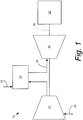
- Fig. 1 shows a schematic view of gas turbine engine 10 as may be used herein.
- the gas turbine engine 10 may include a compressor 15.
- the compressor 15 compresses an incoming flow of air 20.
- the compressor delivers the compressed flow of air 20 to a combustor 25.
- the combustor 25 mixes the compressed flow of air 20 with a compressed flow of fuel 30 and ignites the mixture to create a flow of combustion gases 35.
- the gas turbine engine 10 may include any number of combustors 25.
- the combustor 25 may be in the form of a number of can combustors as will be described in more detail below.
- the flow of combustion gases 35 is in turn delivered to a downstream turbine 40.
- the flow of combustion gases 35 drives the turbine 40 so as to produce mechanical work.
- the mechanical work produced in the turbine 40 drives the compressor 15 via a shaft 45 and an external load 50 such as an electrical generator and the like.
- the gas turbine engine 10 may use natural gas, various types of syngas, and/or other types of fuels.
- the gas turbine engine 10 may be anyone of a number of different gas turbine engines offered by General Electric Company of Schenectady, New York and the like.
- the gas turbine engine 10 may have different configurations and may use other types of components.
- Other types of gas turbine engines also may be used herein.
- Multiple gas turbine engines, other types of turbines, and other types of power generation equipment also may be used herein together.
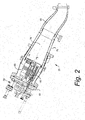
- Fig. 2 shows one example of the can combustor 25.
- the can combustor 25 may include a head end 55.
- the head end 55 generally includes the various manifolds that supply the necessary flows of air 20 and fuel 30.
- the can combustor 25 also includes an end cover 60.
- a number of fuel nozzles 65 may be positioned within the end cover 60.
- a combustion zone 70 may extend downstream of the fuel nozzles 65.
- the combustion zone 70 may be enclosed within a liner 75.
- a transition piece 80 may extend downstream of the combustion zone 70.
- the can combustor 25 described herein is for the purpose of example only. Many other types of combustor designs may be used herein. Other components and other configurations also may be used herein.
- a number of the can combustors 25 may be positioned in a circumferential array.
- the adjacent can combustors 25 may meet at a joint 85.
- the flow of combustion gases 35 may create a wake 90 downstream of the joint 85.
- This wake 90 may be a stagnant flow in a low velocity flow region 92.
- the wakes 90 extend into the airfoils 95 of the turbine 40.
- the wakes 90 extend into the airfoils 95 of a stage one nozzle 96, wherein the combustion gases 35 are accelerated so as to exaggerate the non-uniformities therein.
- the combustion gases 35 then exit the stage one nozzle 96 and enter a stage one bucket 97.
- the wakes 90 within the combustion gases 35 generally mix therein but incur significant mixing and pressure losses.
- Other components and other configurations may be used herein.
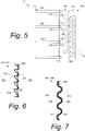
- Fig. 5 shows as portion of a gas turbine engine 100 as may be described herein.
- the gas turbine engine 100 includes a number of adjacent can combustors 110.
- three (3) can combustors 110 are shown: a first can combustor 120 with a first combustion flow 125, a second can combustor 130 with a second combustion flow 135, and a third can combustor 140 with a third combustion flow 145.
- Any number of adjacent can combustors 110 may be used herein.
- Each pair of can combustors 110 meets at a mixing joint 150.
- Each mixing joint 150 may have a flow disruption surface 155 thereon so as to promote mixing of the combustion flows 125, 135, 145.
- the gas turbine engine 100 further includes a turbine 160 positioned downstream of the can combustors 110.
- the turbine 160 includes a number of airfoils 170.
- the airfoils 170 may be arranged as a first stage nozzle 180 and a first stage bucket 190. Any number of nozzles and buckets may be used herein. Other components and other configurations may be used herein.
- Figs. 6-8 show a number of different embodiments of the mixing joint 150 between adjacent can combustors 110 as may be described herein.
- Fig. 6 shows a chevron mixing joint 200.
- the chevron mixing joint 200 may include a first set of chevron like spikes 210 in the first can combustor 120 and a mating second set of chevron like spikes 220 in the second can combustor 130 as the flow disruption surfaces 155.
- the first and second set of chevron like spikes 210, 220 may be formed in a first wall 230 of the first can combustor 120 and an adjacent second wall 240 of the second can combustor 130.
- the depth and angle of the first and second set of chevron like spikes 210, 220 may vary from the first can combustor 120 to the second can combustor 130.
- the number, size, shape, and configuration of the chevron like spikes 210, 220 each may vary.
- Other components and other configurations may be used herein.
- Fig. 7 shows a further embodiment of the mixing joint 150 as may be described herein.
- a lobed mixing joint 250 is shown.
- the lobed mixing joint 250 may include a first set of lobes 260 in the first wall 230 of the first can combustor 120 and a second set 270 of lobes in the second wall 240 of the second can combustor 130 as the flow disruption surfaces 155.
- the first and second set of lobes 260, 270 may have a largely sinusoidal wave like shape and may mate therewith.
- the depth and shape of the first and second set of lobes 260, 270 also may vary.
- the number, size, shape, and configuration of the lobes 260, 270 may vary. Other components and configurations may be used herein.
- Fig. 8 shows a further embodiment of the mixing joint 150.
- the mixing joint 150 may be in the form of a fluidics mixing joint 280 as is shown.
- the fluidics mixing joint 280 may include a number of jets 290 therein that act as a flow disruption surface 155.
- the jets 290 may spray a fluid 300 into the combustion flows 125, 135, 145 as they exit the first can combustor 120 and the second can combustor 130.
- the number, size, shape, and configuration of the jets 290 may vary.
- the nature of the fluid 300 may vary.
- Other components and configurations may be used herein.
- the use of the mixing joints 150 described herein thus results in a wake 310 that is much smaller than the wake 90 described above.
- the wake 310 mixes with low losses in a low velocity region 320 immediately downstream of the mixing joint 150 and before entry into the first stage nozzle 180.
- the various geometries of the flow disruption surfaces 155 of the mixing joint 150 enhance the mixing of the combustion flows 125, 135, 145 from adjacent can combustors 110 in the low velocity region 320 into a mixed flow 330, thus resulting in significantly less mixing losses as compared to mixing downstream in the first stage nozzle 180, the first stage bucket 190, or elsewhere.
- This improved mixing thus reduces the overall pressure losses in the gas turbine engine 100 as a whole without increasing the axial distance between the can combustors 110 and the turbine 160.
- mixing joint 150 is for purposes of example only. Any other mixing joint geometry or other type of flow disruption surface 155 that encourages mixing of the combustion flows 125, 135, 145 from adjacent can combustors 110 before entry into the turbine 160 may be used herein. Different types of flow disruption surfaces 155 may be used herein together. Other components and other configurations also may be used herein.
Landscapes
- Engineering & Computer Science (AREA)
- Mechanical Engineering (AREA)
- General Engineering & Computer Science (AREA)
- Chemical & Material Sciences (AREA)
- Combustion & Propulsion (AREA)
- Combustion Of Fluid Fuel (AREA)
Abstract
Description
- The present application relates generally to gas turbine engines and more particularly relates to a joint between adjacent annular can combustors to promote mixing of the respective combustion streams downstream thereof before entry into the first stage of the turbine.
- Annular combustors often are used with gas turbine engines. Generally described, an annular combustor may have a number of individual can combustors that are circumferentially spaced between a compressor and a turbine. Each can combustor separately generates combustion gases that are directed downstream towards the first stage of the turbine.
- The mixing of these separate combustion streams is largely a function of the free stream Mach number at which the mixing is taking place as well as the differences in momentum and energy between the combustion streams. Moreover, a stagnant flow region or wake in a low flow velocity region may exist downstream of a joint between adjacent can combustors due to the bluntness of the joint. As such, the non-uniform combustor flows may have a Mach number of only about 0.1 when leaving the can combustors. Practically speaking, the axial distance between the exit of the can combustors and the leading edge of a first stage nozzle is relatively small such that little mixing actually may take place before entry into the turbine.
- The combustor flows then may be strongly accelerated in the stage one nozzle to a Mach number of about 1.0. This acceleration may exaggerate the non-uniformities in the flow fields and hence create more mixing losses downstream thereof. As the now strongly nonuniform flow field enters the stage one bucket, the majority of mixing losses may take place therein as the wakes from the can combustor joints may be mixed by an unsteady flow process.
- There is thus a desire therefore for an improved combustor design that may minimize mixing loses. Such reduced mixing loses may reduce overall pressure losses without increasing the axial distance between the combustor and the turbine. Such an improved combustion design thus should improve overall system performance and efficiency.
- The present invention resides in a mixing joint for adjacent can combustors. The mixing joint may include a first can combustor with a first combustion flow and a first wall, a second can combustor with a second combustion flow and a second wall, and a flow disruption surface positioned about the first wall and the second wall to promote mixing of the first combustion flow and the second combustion flow.
- The present invention further resides in a method of limiting pressure losses in a gas turbine engine. The method may include the steps of positioning a mixing joint with a flow disruption surface on a number of can combustors, generating a number of combustion streams in the can combustors, substantially mixing the combustion streams in a low velocity region downstream of the can combustors, and passing a mixed stream to a turbine.
- The present invention further resides in a gas turbine engine. The gas turbine engine may include a number of can combustors, and a mixing joint as described above positioned between each pair of the can combustors, and a turbine downstream of the can combustors.
- These and other features and improvements of the present application will become apparent to one of ordinary skill in the art upon review of the following detailed description when taken in conjunction with the several drawings and the appended claims.
- Embodiments of the present invention will now be described, by way of example only, with reference to the accompanying drawings in which:
-
Fig. 1 is a schematic view of a known gas turbine engine that may be used herein. -
Fig. 2 is a side cross-sectional view of a can combustor that may be used with the gas turbine engine ofFig. 1 . -
Fig. 3 is a schematic view of a number of adjacent can combustors. -
Fig. 4 is a schematic view of a number of adjacent can combustors and the first two rows of turbine airfoils with a wake downstream of the can combustors. -
Fig. 5 is a schematic view of a number of adjacent can combustors and the first two rows of turbine airfoils illustrating the use of the can combustor mixing joints as may be described herein. -
Fig. 6 is a schematic view of a can combustor mixing joint as may be described herein. -
Fig. 7 is a schematic view of an alternative embodiment of a can combustor mixing joint as may be described herein. -
Fig. 8 is a schematic view of an alternative embodiment of a can combustor mixing joint as may be described herein. - Referring now to the drawings, in which like numerals refer to like elements throughout the several views,
Fig. 1 shows a schematic view ofgas turbine engine 10 as may be used herein. Thegas turbine engine 10 may include acompressor 15. Thecompressor 15 compresses an incoming flow ofair 20. The compressor delivers the compressed flow ofair 20 to acombustor 25. Thecombustor 25 mixes the compressed flow ofair 20 with a compressed flow offuel 30 and ignites the mixture to create a flow ofcombustion gases 35. Although only asingle combustor 25 is shown, thegas turbine engine 10 may include any number ofcombustors 25. In this example, thecombustor 25 may be in the form of a number of can combustors as will be described in more detail below. The flow ofcombustion gases 35 is in turn delivered to adownstream turbine 40. The flow ofcombustion gases 35 drives theturbine 40 so as to produce mechanical work. The mechanical work produced in theturbine 40 drives thecompressor 15 via ashaft 45 and anexternal load 50 such as an electrical generator and the like. - The
gas turbine engine 10 may use natural gas, various types of syngas, and/or other types of fuels. Thegas turbine engine 10 may be anyone of a number of different gas turbine engines offered by General Electric Company of Schenectady, New York and the like. Thegas turbine engine 10 may have different configurations and may use other types of components. Other types of gas turbine engines also may be used herein. Multiple gas turbine engines, other types of turbines, and other types of power generation equipment also may be used herein together. -
Fig. 2 shows one example of thecan combustor 25. Generally described, the cancombustor 25 may include ahead end 55. Thehead end 55 generally includes the various manifolds that supply the necessary flows ofair 20 andfuel 30. Thecan combustor 25 also includes anend cover 60. A number offuel nozzles 65 may be positioned within theend cover 60. Acombustion zone 70 may extend downstream of thefuel nozzles 65. Thecombustion zone 70 may be enclosed within aliner 75. Atransition piece 80 may extend downstream of thecombustion zone 70. Thecan combustor 25 described herein is for the purpose of example only. Many other types of combustor designs may be used herein. Other components and other configurations also may be used herein. - As is shown in
Fig. 3 , a number of thecan combustors 25 may be positioned in a circumferential array. Likewise, as is shown inFig. 4 , the adjacent cancombustors 25 may meet at ajoint 85. As was described above, the flow ofcombustion gases 35 may create awake 90 downstream of thejoint 85. Thiswake 90 may be a stagnant flow in a lowvelocity flow region 92. Thewakes 90 extend into theairfoils 95 of theturbine 40. Specifically, thewakes 90 extend into theairfoils 95 of a stage onenozzle 96, wherein thecombustion gases 35 are accelerated so as to exaggerate the non-uniformities therein. Thecombustion gases 35 then exit the stage onenozzle 96 and enter a stage onebucket 97. Thewakes 90 within thecombustion gases 35 generally mix therein but incur significant mixing and pressure losses. Other components and other configurations may be used herein. -
Fig. 5 shows as portion of agas turbine engine 100 as may be described herein. Thegas turbine engine 100 includes a number of adjacent can combustors 110. In this example, three (3) can combustors 110 are shown: a first can combustor 120 with afirst combustion flow 125, a second can combustor 130 with asecond combustion flow 135, and athird can combustor 140 with athird combustion flow 145. Any number of adjacent can combustors 110 may be used herein. Each pair of can combustors 110 meets at a mixing joint 150. Each mixing joint 150 may have a flow disruption surface 155 thereon so as to promote mixing of the combustion flows 125, 135, 145. Thegas turbine engine 100 further includes aturbine 160 positioned downstream of thecan combustors 110. Theturbine 160 includes a number ofairfoils 170. In this example, theairfoils 170 may be arranged as afirst stage nozzle 180 and afirst stage bucket 190. Any number of nozzles and buckets may be used herein. Other components and other configurations may be used herein. -
Figs. 6-8 show a number of different embodiments of the mixing joint 150 between adjacent can combustors 110 as may be described herein.Fig. 6 shows a chevron mixing joint 200. The chevron mixing joint 200 may include a first set of chevron likespikes 210 in the first can combustor 120 and a mating second set of chevron likespikes 220 in the second can combustor 130 as the flow disruption surfaces 155. The first and second set of chevron likespikes first wall 230 of the first can combustor 120 and an adjacentsecond wall 240 of the second can combustor 130. As is shown, the depth and angle of the first and second set of chevron likespikes spikes -
Fig. 7 shows a further embodiment of the mixing joint 150 as may be described herein. In this embodiment, a lobed mixing joint 250 is shown. The lobed mixing joint 250 may include a first set oflobes 260 in thefirst wall 230 of the first can combustor 120 and asecond set 270 of lobes in thesecond wall 240 of the second can combustor 130 as the flow disruption surfaces 155. The first and second set oflobes lobes lobes -
Fig. 8 shows a further embodiment of the mixing joint 150. In this example, the mixing joint 150 may be in the form of a fluidics mixing joint 280 as is shown. The fluidics mixing joint 280 may include a number ofjets 290 therein that act as a flow disruption surface 155. Thejets 290 may spray a fluid 300 into the combustion flows 125, 135, 145 as they exit the first can combustor 120 and the second can combustor 130. The number, size, shape, and configuration of thejets 290 may vary. Likewise, the nature of the fluid 300 may vary. Other components and configurations may be used herein. - Referring again to
Fig. 5 , the use of the mixingjoints 150 described herein thus results in awake 310 that is much smaller than the wake 90 described above. Specifically, thewake 310 mixes with low losses in alow velocity region 320 immediately downstream of the mixing joint 150 and before entry into thefirst stage nozzle 180. The various geometries of the flow disruption surfaces 155 of the mixing joint 150 enhance the mixing of the combustion flows 125, 135, 145 from adjacent can combustors 110 in thelow velocity region 320 into amixed flow 330, thus resulting in significantly less mixing losses as compared to mixing downstream in thefirst stage nozzle 180, thefirst stage bucket 190, or elsewhere. This improved mixing thus reduces the overall pressure losses in thegas turbine engine 100 as a whole without increasing the axial distance between the can combustors 110 and theturbine 160. - The embodiments of the mixing joint 150 described herein are for purposes of example only. Any other mixing joint geometry or other type of flow disruption surface 155 that encourages mixing of the combustion flows 125, 135, 145 from adjacent can combustors 110 before entry into the
turbine 160 may be used herein. Different types of flow disruption surfaces 155 may be used herein together. Other components and other configurations also may be used herein. - It should be apparent that the foregoing relates only to certain embodiments of the present application and that numerous changes and modifications may be made herein by one of ordinary skill in the art without departing from the general spirit and scope of the invention as defined by the following claims and the equivalents thereof.
Claims (12)
- A mixing joint (150,200,250) for adjacent can combustors (120,130), comprising:a first can combustor (120) with a first combustion flow (125) and a first wall (230);a second can combustor (130) with a second combustion flow (135) and a second wall (240); anda flow disruption surface (155) positioned about the first wall (230) and the second wall (240) to promote mixing of the first combustion flow (125) and the second combustion flow (135).
- The mixing joint (150,200,250) of claim 1, wherein the flow disruption surface (155) comprises a first set of spikes (210) on the first wall (230) and a second set of spikes (220) on the second wall (240).
- The mixing joint (150,200,250) of claim 2, wherein the first set of spikes (210) and the second set of spikes (220) comprise differing depths.
- The mixing joint (150,200,250) of claim 2, wherein the first set of spikes (210) and the second set of spikes (220) comprise a chevron like spike.
- The mixing joint (150,200,250) of claim 1, wherein the flow disruption surface (155) comprises a first set of lobes (260) on the first wall (230) and a second set of lobes (270) on the second wall (240).
- The mixing joint (150,200,250) of claim 5, wherein the first set of lobes (260) and the second set of lobes (270) comprise differing depths.
- The mixing joint (150,200,250) of claim 5, wherein the first set of lobes (260) and the second set of lobes (270) comprise a sinusoidal like shape.
- The mixing joint (150,200,250) of claim 1, wherein the flow disruption surface (155) comprises a plurality of jets (290) on the first wall (230) and/or the second wall (240).
- The mixing joint (150,200,250) of claim 8, further comprising a fluid spraying (300) from the plurality of jets (290).
- The mixing joint (150,200,250) of any preceding claim, further comprising a low velocity region (320) downstream of the first wall (230) and the second wall (240) and wherein the first combustion flow (125) and the second combustion flow (135) substantially mix within the low velocity region (320).
- A method of limiting pressure losses in a gas turbine engine (10,100), comprising:positioning a mixing joint (150,200,250) with a flow disruption surface (155) on a plurality of can combustors (110);generating a plurality of combustion streams (125135,145) in the plurality of can combustors;substantially mixing the plurality of combustion streams (125,135,145) in a low velocity region (320) downstream of the plurality of can combustors (110); andpassing a mixed stream to a turbine (100).
- A gas turbine engine (10,100), comprising:a plurality of can combustors (110);a mixing joint (150,200,250) as recited in any of claims 1 to 10 positioned between each pair of the plurality of can combustors (100), and a turbine downstream of the plurality of can combustors.
Applications Claiming Priority (1)
| Application Number | Priority Date | Filing Date | Title |
|---|---|---|---|
| US13/036,084 US10030872B2 (en) | 2011-02-28 | 2011-02-28 | Combustor mixing joint with flow disruption surface |
Publications (3)
| Publication Number | Publication Date |
|---|---|
| EP2492596A2 true EP2492596A2 (en) | 2012-08-29 |
| EP2492596A3 EP2492596A3 (en) | 2014-01-15 |
| EP2492596B1 EP2492596B1 (en) | 2016-05-18 |
Family
ID=45771698
Family Applications (1)
| Application Number | Title | Priority Date | Filing Date |
|---|---|---|---|
| EP12157134.3A Active EP2492596B1 (en) | 2011-02-28 | 2012-02-27 | Combustor mixing joint |
Country Status (3)
| Country | Link |
|---|---|
| US (1) | US10030872B2 (en) |
| EP (1) | EP2492596B1 (en) |
| CN (1) | CN102654287B (en) |
Cited By (2)
| Publication number | Priority date | Publication date | Assignee | Title |
|---|---|---|---|---|
| EP2725198A1 (en) * | 2012-10-24 | 2014-04-30 | Alstom Technology Ltd | Combustor transition |
| EP2725197A1 (en) * | 2012-10-24 | 2014-04-30 | Alstom Technology Ltd | Combustor transition |
Families Citing this family (10)
| Publication number | Priority date | Publication date | Assignee | Title |
|---|---|---|---|---|
| JP5886040B2 (en) * | 2011-12-28 | 2016-03-16 | 三菱日立パワーシステムズ株式会社 | gas turbine |
| US9121613B2 (en) * | 2012-06-05 | 2015-09-01 | General Electric Company | Combustor with brief quench zone with slots |
| US9458732B2 (en) * | 2013-10-25 | 2016-10-04 | General Electric Company | Transition duct assembly with modified trailing edge in turbine system |
| US20150167979A1 (en) * | 2013-12-17 | 2015-06-18 | General Electric Company | First stage nozzle or transition nozzle configured to promote mixing of respective combustion streams downstream thereof before entry into a first stage bucket of a turbine |
| DE112015003797B4 (en) * | 2014-08-19 | 2022-08-18 | Mitsubishi Heavy Industries, Ltd. | GAS TURBINE |
| US10450868B2 (en) | 2016-07-22 | 2019-10-22 | General Electric Company | Turbine rotor blade with coupon having corrugated surface(s) |
| US10465525B2 (en) | 2016-07-22 | 2019-11-05 | General Electric Company | Blade with internal rib having corrugated surface(s) |
| US10465520B2 (en) | 2016-07-22 | 2019-11-05 | General Electric Company | Blade with corrugated outer surface(s) |
| US10443399B2 (en) | 2016-07-22 | 2019-10-15 | General Electric Company | Turbine vane with coupon having corrugated surface(s) |
| US10436037B2 (en) | 2016-07-22 | 2019-10-08 | General Electric Company | Blade with parallel corrugated surfaces on inner and outer surfaces |
Family Cites Families (27)
| Publication number | Priority date | Publication date | Assignee | Title |
|---|---|---|---|---|
| US2702454A (en) * | 1951-06-07 | 1955-02-22 | United Aircraft Corp | Transition piece providing a connection between the combustion chambers and the turbine nozzle in gas turbine power plants |
| US3578264A (en) * | 1968-07-09 | 1971-05-11 | Battelle Development Corp | Boundary layer control of flow separation and heat exchange |
| GB1253097A (en) * | 1969-03-21 | 1971-11-10 | ||
| US3657882A (en) | 1970-11-13 | 1972-04-25 | Westinghouse Electric Corp | Combustion apparatus |
| US3776363A (en) * | 1971-05-10 | 1973-12-04 | A Kuethe | Control of noise and instabilities in jet engines, compressors, turbines, heat exchangers and the like |
| US4149375A (en) * | 1976-11-29 | 1979-04-17 | United Technologies Corporation | Lobe mixer for gas turbine engine |
| US4830315A (en) * | 1986-04-30 | 1989-05-16 | United Technologies Corporation | Airfoil-shaped body |
| US5110560A (en) * | 1987-11-23 | 1992-05-05 | United Technologies Corporation | Convoluted diffuser |
| US5010453A (en) * | 1990-08-28 | 1991-04-23 | General Motors Corporation | Vehicle lamp ventilation system |
| US5983641A (en) * | 1997-04-30 | 1999-11-16 | Mitsubishi Heavy Industries, Ltd. | Tail pipe of gas turbine combustor and gas turbine combustor having the same tail pipe |
| US6006523A (en) * | 1997-04-30 | 1999-12-28 | Mitsubishi Heavy Industries, Ltd. | Gas turbine combustor with angled tube section |
| US6360528B1 (en) | 1997-10-31 | 2002-03-26 | General Electric Company | Chevron exhaust nozzle for a gas turbine engine |
| AU2002211367A1 (en) | 2000-10-02 | 2002-04-15 | Rohr, Inc. | Apparatus, method and system for gas turbine engine noise reduction |
| EP1338793A3 (en) * | 2002-02-22 | 2010-09-01 | Mitsubishi Heavy Industries, Ltd. | Serrated wind turbine blade trailing edge |
| US6907724B2 (en) | 2002-09-13 | 2005-06-21 | The Boeing Company | Combined cycle engines incorporating swirl augmented combustion for reduced volume and weight and improved performance |
| US6840048B2 (en) * | 2002-09-26 | 2005-01-11 | General Electric Company | Dynamically uncoupled can combustor |
| US7234304B2 (en) * | 2002-10-23 | 2007-06-26 | Pratt & Whitney Canada Corp | Aerodynamic trip to improve acoustic transmission loss and reduce noise level for gas turbine engine |
| US7571611B2 (en) | 2006-04-24 | 2009-08-11 | General Electric Company | Methods and system for reducing pressure losses in gas turbine engines |
| EP1894616A1 (en) * | 2006-08-30 | 2008-03-05 | Fachhochschule Zentralschweiz | Static mixing device |
| US20090145132A1 (en) | 2007-12-07 | 2009-06-11 | General Electric Company | Methods and system for reducing pressure losses in gas turbine engines |
| JP2009197650A (en) * | 2008-02-20 | 2009-09-03 | Mitsubishi Heavy Ind Ltd | Gas turbine |
| GB0810500D0 (en) * | 2008-06-09 | 2008-07-09 | Airbus Uk Ltd | Aircraft wing |
| US8245515B2 (en) | 2008-08-06 | 2012-08-21 | General Electric Company | Transition duct aft end frame cooling and related method |
| US8091365B2 (en) * | 2008-08-12 | 2012-01-10 | Siemens Energy, Inc. | Canted outlet for transition in a gas turbine engine |
| US8065881B2 (en) * | 2008-08-12 | 2011-11-29 | Siemens Energy, Inc. | Transition with a linear flow path with exhaust mouths for use in a gas turbine engine |
| US8087253B2 (en) | 2008-11-20 | 2012-01-03 | General Electric Company | Methods, apparatus and systems concerning the circumferential clocking of turbine airfoils in relation to combustor cans and the flow of cooling air through the turbine hot gas flowpath |
| US20130291548A1 (en) * | 2011-02-28 | 2013-11-07 | General Electric Company | Combustor mixing joint and methods of improving durability of a first stage bucket of a turbine |
-
2011
- 2011-02-28 US US13/036,084 patent/US10030872B2/en active Active
-
2012
- 2012-02-27 EP EP12157134.3A patent/EP2492596B1/en active Active
- 2012-02-28 CN CN201210059059.9A patent/CN102654287B/en active Active
Non-Patent Citations (1)
| Title |
|---|
| None |
Cited By (7)
| Publication number | Priority date | Publication date | Assignee | Title |
|---|---|---|---|---|
| EP2725198A1 (en) * | 2012-10-24 | 2014-04-30 | Alstom Technology Ltd | Combustor transition |
| EP2725197A1 (en) * | 2012-10-24 | 2014-04-30 | Alstom Technology Ltd | Combustor transition |
| EP2725196A1 (en) * | 2012-10-24 | 2014-04-30 | Alstom Technology Ltd | Combustor transition |
| EP2725199A1 (en) * | 2012-10-24 | 2014-04-30 | Alstom Technology Ltd | Combustor transition |
| RU2566867C2 (en) * | 2012-10-24 | 2015-10-27 | Альстом Текнолоджи Лтд | Transient part of combustion chamber; tubular combustion chamber; gas-turbine engine and methods of its modernisation and boroscopic inspection |
| US9429032B2 (en) | 2012-10-24 | 2016-08-30 | General Electric Technology Gmbh | Combustor transition |
| US9482106B2 (en) | 2012-10-24 | 2016-11-01 | General Electric Technology Gmbh | Combustor transition |
Also Published As
| Publication number | Publication date |
|---|---|
| CN102654287B (en) | 2016-02-17 |
| US10030872B2 (en) | 2018-07-24 |
| EP2492596A3 (en) | 2014-01-15 |
| CN102654287A (en) | 2012-09-05 |
| US20120216542A1 (en) | 2012-08-30 |
| EP2492596B1 (en) | 2016-05-18 |
Similar Documents
| Publication | Publication Date | Title |
|---|---|---|
| EP2492596B1 (en) | Combustor mixing joint | |
| US20130291548A1 (en) | Combustor mixing joint and methods of improving durability of a first stage bucket of a turbine | |
| US20150167979A1 (en) | First stage nozzle or transition nozzle configured to promote mixing of respective combustion streams downstream thereof before entry into a first stage bucket of a turbine | |
| US8967959B2 (en) | Turbine of a turbomachine | |
| EP2562479B1 (en) | Wall elements for gas turbine engines | |
| EP2612991B1 (en) | Turbine nozzle with a flow groove | |
| US9458732B2 (en) | Transition duct assembly with modified trailing edge in turbine system | |
| US8511990B2 (en) | Cooling hole exits for a turbine bucket tip shroud | |
| US10753615B2 (en) | Dual fuel concentric nozzle for a gas turbine | |
| US9546601B2 (en) | Clocked combustor can array | |
| EP2647799B1 (en) | Gas turbine can combustor with oval or elliptic head end | |
| EP3015651A1 (en) | A cooled gas turbine blade comprising swirl features inside a cooling cavity | |
| US20140360155A1 (en) | Microchannel systems and methods for cooling turbine components of a gas turbine engine | |
| EP2584144A2 (en) | Transition nozzle | |
| EP2578940A2 (en) | Combustor and method for supplying flow to a combustor | |
| US20170356652A1 (en) | Combustor Effusion Plate Assembly | |
| EP3141818A1 (en) | Cooling apparatus for a fuel injector | |
| EP2503243A1 (en) | Combustor with fuel nozzle liner having chevron ribs | |
| US20180179950A1 (en) | Turbine engine assembly including a rotating detonation combustor | |
| US20130234396A1 (en) | Transition Piece Aft-Frame Seals | |
| EP2647800B1 (en) | Transition nozzle combustion system | |
| US20150338101A1 (en) | Turbomachine combustor including a combustor sleeve baffle | |
| EP3531021B1 (en) | Conduit | |
| US20150028133A1 (en) | Enhanced Mixing Tube Elements | |
| US9644539B2 (en) | Cooling air temperature reduction using nozzles |
Legal Events
| Date | Code | Title | Description |
|---|---|---|---|
| PUAI | Public reference made under article 153(3) epc to a published international application that has entered the european phase |
Free format text: ORIGINAL CODE: 0009012 |
|
| AK | Designated contracting states |
Kind code of ref document: A2 Designated state(s): AL AT BE BG CH CY CZ DE DK EE ES FI FR GB GR HR HU IE IS IT LI LT LU LV MC MK MT NL NO PL PT RO RS SE SI SK SM TR |
|
| AX | Request for extension of the european patent |
Extension state: BA ME |
|
| PUAL | Search report despatched |
Free format text: ORIGINAL CODE: 0009013 |
|
| AK | Designated contracting states |
Kind code of ref document: A3 Designated state(s): AL AT BE BG CH CY CZ DE DK EE ES FI FR GB GR HR HU IE IS IT LI LT LU LV MC MK MT NL NO PL PT RO RS SE SI SK SM TR |
|
| AX | Request for extension of the european patent |
Extension state: BA ME |
|
| RIC1 | Information provided on ipc code assigned before grant |
Ipc: F23R 3/46 20060101AFI20131206BHEP Ipc: F01D 9/02 20060101ALI20131206BHEP |
|
| 17P | Request for examination filed |
Effective date: 20140715 |
|
| RBV | Designated contracting states (corrected) |
Designated state(s): AL AT BE BG CH CY CZ DE DK EE ES FI FR GB GR HR HU IE IS IT LI LT LU LV MC MK MT NL NO PL PT RO RS SE SI SK SM TR |
|
| 17Q | First examination report despatched |
Effective date: 20140915 |
|
| GRAP | Despatch of communication of intention to grant a patent |
Free format text: ORIGINAL CODE: EPIDOSNIGR1 |
|
| INTG | Intention to grant announced |
Effective date: 20160126 |
|
| GRAS | Grant fee paid |
Free format text: ORIGINAL CODE: EPIDOSNIGR3 |
|
| GRAA | (expected) grant |
Free format text: ORIGINAL CODE: 0009210 |
|
| AK | Designated contracting states |
Kind code of ref document: B1 Designated state(s): AL AT BE BG CH CY CZ DE DK EE ES FI FR GB GR HR HU IE IS IT LI LT LU LV MC MK MT NL NO PL PT RO RS SE SI SK SM TR |
|
| REG | Reference to a national code |
Ref country code: GB Ref legal event code: FG4D |
|
| REG | Reference to a national code |
Ref country code: CH Ref legal event code: EP |
|
| REG | Reference to a national code |
Ref country code: IE Ref legal event code: FG4D Ref country code: AT Ref legal event code: REF Ref document number: 800828 Country of ref document: AT Kind code of ref document: T Effective date: 20160615 |
|
| REG | Reference to a national code |
Ref country code: DE Ref legal event code: R096 Ref document number: 602012018431 Country of ref document: DE |
|
| REG | Reference to a national code |
Ref country code: NL Ref legal event code: MP Effective date: 20160518 |
|
| REG | Reference to a national code |
Ref country code: LT Ref legal event code: MG4D |
|
| PG25 | Lapsed in a contracting state [announced via postgrant information from national office to epo] |
Ref country code: NO Free format text: LAPSE BECAUSE OF FAILURE TO SUBMIT A TRANSLATION OF THE DESCRIPTION OR TO PAY THE FEE WITHIN THE PRESCRIBED TIME-LIMIT Effective date: 20160818 Ref country code: LT Free format text: LAPSE BECAUSE OF FAILURE TO SUBMIT A TRANSLATION OF THE DESCRIPTION OR TO PAY THE FEE WITHIN THE PRESCRIBED TIME-LIMIT Effective date: 20160518 Ref country code: FI Free format text: LAPSE BECAUSE OF FAILURE TO SUBMIT A TRANSLATION OF THE DESCRIPTION OR TO PAY THE FEE WITHIN THE PRESCRIBED TIME-LIMIT Effective date: 20160518 Ref country code: NL Free format text: LAPSE BECAUSE OF FAILURE TO SUBMIT A TRANSLATION OF THE DESCRIPTION OR TO PAY THE FEE WITHIN THE PRESCRIBED TIME-LIMIT Effective date: 20160518 |
|
| REG | Reference to a national code |
Ref country code: AT Ref legal event code: MK05 Ref document number: 800828 Country of ref document: AT Kind code of ref document: T Effective date: 20160518 |
|
| PG25 | Lapsed in a contracting state [announced via postgrant information from national office to epo] |
Ref country code: LV Free format text: LAPSE BECAUSE OF FAILURE TO SUBMIT A TRANSLATION OF THE DESCRIPTION OR TO PAY THE FEE WITHIN THE PRESCRIBED TIME-LIMIT Effective date: 20160518 Ref country code: ES Free format text: LAPSE BECAUSE OF FAILURE TO SUBMIT A TRANSLATION OF THE DESCRIPTION OR TO PAY THE FEE WITHIN THE PRESCRIBED TIME-LIMIT Effective date: 20160518 Ref country code: RS Free format text: LAPSE BECAUSE OF FAILURE TO SUBMIT A TRANSLATION OF THE DESCRIPTION OR TO PAY THE FEE WITHIN THE PRESCRIBED TIME-LIMIT Effective date: 20160518 Ref country code: HR Free format text: LAPSE BECAUSE OF FAILURE TO SUBMIT A TRANSLATION OF THE DESCRIPTION OR TO PAY THE FEE WITHIN THE PRESCRIBED TIME-LIMIT Effective date: 20160518 Ref country code: GR Free format text: LAPSE BECAUSE OF FAILURE TO SUBMIT A TRANSLATION OF THE DESCRIPTION OR TO PAY THE FEE WITHIN THE PRESCRIBED TIME-LIMIT Effective date: 20160819 Ref country code: SE Free format text: LAPSE BECAUSE OF FAILURE TO SUBMIT A TRANSLATION OF THE DESCRIPTION OR TO PAY THE FEE WITHIN THE PRESCRIBED TIME-LIMIT Effective date: 20160518 Ref country code: PT Free format text: LAPSE BECAUSE OF FAILURE TO SUBMIT A TRANSLATION OF THE DESCRIPTION OR TO PAY THE FEE WITHIN THE PRESCRIBED TIME-LIMIT Effective date: 20160919 |
|
| PG25 | Lapsed in a contracting state [announced via postgrant information from national office to epo] |
Ref country code: CZ Free format text: LAPSE BECAUSE OF FAILURE TO SUBMIT A TRANSLATION OF THE DESCRIPTION OR TO PAY THE FEE WITHIN THE PRESCRIBED TIME-LIMIT Effective date: 20160518 Ref country code: SK Free format text: LAPSE BECAUSE OF FAILURE TO SUBMIT A TRANSLATION OF THE DESCRIPTION OR TO PAY THE FEE WITHIN THE PRESCRIBED TIME-LIMIT Effective date: 20160518 Ref country code: RO Free format text: LAPSE BECAUSE OF FAILURE TO SUBMIT A TRANSLATION OF THE DESCRIPTION OR TO PAY THE FEE WITHIN THE PRESCRIBED TIME-LIMIT Effective date: 20160518 Ref country code: EE Free format text: LAPSE BECAUSE OF FAILURE TO SUBMIT A TRANSLATION OF THE DESCRIPTION OR TO PAY THE FEE WITHIN THE PRESCRIBED TIME-LIMIT Effective date: 20160518 Ref country code: DK Free format text: LAPSE BECAUSE OF FAILURE TO SUBMIT A TRANSLATION OF THE DESCRIPTION OR TO PAY THE FEE WITHIN THE PRESCRIBED TIME-LIMIT Effective date: 20160518 |
|
| REG | Reference to a national code |
Ref country code: DE Ref legal event code: R097 Ref document number: 602012018431 Country of ref document: DE |
|
| REG | Reference to a national code |
Ref country code: FR Ref legal event code: PLFP Year of fee payment: 6 |
|
| PG25 | Lapsed in a contracting state [announced via postgrant information from national office to epo] |
Ref country code: PL Free format text: LAPSE BECAUSE OF FAILURE TO SUBMIT A TRANSLATION OF THE DESCRIPTION OR TO PAY THE FEE WITHIN THE PRESCRIBED TIME-LIMIT Effective date: 20160518 Ref country code: AT Free format text: LAPSE BECAUSE OF FAILURE TO SUBMIT A TRANSLATION OF THE DESCRIPTION OR TO PAY THE FEE WITHIN THE PRESCRIBED TIME-LIMIT Effective date: 20160518 Ref country code: SM Free format text: LAPSE BECAUSE OF FAILURE TO SUBMIT A TRANSLATION OF THE DESCRIPTION OR TO PAY THE FEE WITHIN THE PRESCRIBED TIME-LIMIT Effective date: 20160518 Ref country code: BE Free format text: LAPSE BECAUSE OF FAILURE TO SUBMIT A TRANSLATION OF THE DESCRIPTION OR TO PAY THE FEE WITHIN THE PRESCRIBED TIME-LIMIT Effective date: 20160518 |
|
| PLBE | No opposition filed within time limit |
Free format text: ORIGINAL CODE: 0009261 |
|
| STAA | Information on the status of an ep patent application or granted ep patent |
Free format text: STATUS: NO OPPOSITION FILED WITHIN TIME LIMIT |
|
| 26N | No opposition filed |
Effective date: 20170221 |
|
| PG25 | Lapsed in a contracting state [announced via postgrant information from national office to epo] |
Ref country code: SI Free format text: LAPSE BECAUSE OF FAILURE TO SUBMIT A TRANSLATION OF THE DESCRIPTION OR TO PAY THE FEE WITHIN THE PRESCRIBED TIME-LIMIT Effective date: 20160518 |
|
| PG25 | Lapsed in a contracting state [announced via postgrant information from national office to epo] |
Ref country code: MC Free format text: LAPSE BECAUSE OF FAILURE TO SUBMIT A TRANSLATION OF THE DESCRIPTION OR TO PAY THE FEE WITHIN THE PRESCRIBED TIME-LIMIT Effective date: 20160518 |
|
| REG | Reference to a national code |
Ref country code: IE Ref legal event code: MM4A |
|
| PG25 | Lapsed in a contracting state [announced via postgrant information from national office to epo] |
Ref country code: LU Free format text: LAPSE BECAUSE OF NON-PAYMENT OF DUE FEES Effective date: 20170227 |
|
| REG | Reference to a national code |
Ref country code: FR Ref legal event code: PLFP Year of fee payment: 7 |
|
| PG25 | Lapsed in a contracting state [announced via postgrant information from national office to epo] |
Ref country code: IE Free format text: LAPSE BECAUSE OF NON-PAYMENT OF DUE FEES Effective date: 20170227 |
|
| PG25 | Lapsed in a contracting state [announced via postgrant information from national office to epo] |
Ref country code: MT Free format text: LAPSE BECAUSE OF NON-PAYMENT OF DUE FEES Effective date: 20170227 |
|
| PG25 | Lapsed in a contracting state [announced via postgrant information from national office to epo] |
Ref country code: AL Free format text: LAPSE BECAUSE OF FAILURE TO SUBMIT A TRANSLATION OF THE DESCRIPTION OR TO PAY THE FEE WITHIN THE PRESCRIBED TIME-LIMIT Effective date: 20160518 |
|
| PG25 | Lapsed in a contracting state [announced via postgrant information from national office to epo] |
Ref country code: HU Free format text: LAPSE BECAUSE OF FAILURE TO SUBMIT A TRANSLATION OF THE DESCRIPTION OR TO PAY THE FEE WITHIN THE PRESCRIBED TIME-LIMIT; INVALID AB INITIO Effective date: 20120227 |
|
| PG25 | Lapsed in a contracting state [announced via postgrant information from national office to epo] |
Ref country code: BG Free format text: LAPSE BECAUSE OF FAILURE TO SUBMIT A TRANSLATION OF THE DESCRIPTION OR TO PAY THE FEE WITHIN THE PRESCRIBED TIME-LIMIT Effective date: 20160518 |
|
| PG25 | Lapsed in a contracting state [announced via postgrant information from national office to epo] |
Ref country code: CY Free format text: LAPSE BECAUSE OF NON-PAYMENT OF DUE FEES Effective date: 20160518 |
|
| PG25 | Lapsed in a contracting state [announced via postgrant information from national office to epo] |
Ref country code: MK Free format text: LAPSE BECAUSE OF FAILURE TO SUBMIT A TRANSLATION OF THE DESCRIPTION OR TO PAY THE FEE WITHIN THE PRESCRIBED TIME-LIMIT Effective date: 20160518 |
|
| PG25 | Lapsed in a contracting state [announced via postgrant information from national office to epo] |
Ref country code: TR Free format text: LAPSE BECAUSE OF FAILURE TO SUBMIT A TRANSLATION OF THE DESCRIPTION OR TO PAY THE FEE WITHIN THE PRESCRIBED TIME-LIMIT Effective date: 20160518 |
|
| PGFP | Annual fee paid to national office [announced via postgrant information from national office to epo] |
Ref country code: GB Payment date: 20200123 Year of fee payment: 9 |
|
| PGFP | Annual fee paid to national office [announced via postgrant information from national office to epo] |
Ref country code: CH Payment date: 20200123 Year of fee payment: 9 |
|
| PGFP | Annual fee paid to national office [announced via postgrant information from national office to epo] |
Ref country code: FR Payment date: 20200122 Year of fee payment: 9 |
|
| PG25 | Lapsed in a contracting state [announced via postgrant information from national office to epo] |
Ref country code: IS Free format text: LAPSE BECAUSE OF FAILURE TO SUBMIT A TRANSLATION OF THE DESCRIPTION OR TO PAY THE FEE WITHIN THE PRESCRIBED TIME-LIMIT Effective date: 20160918 |
|
| GBPC | Gb: european patent ceased through non-payment of renewal fee |
Effective date: 20210227 |
|
| PG25 | Lapsed in a contracting state [announced via postgrant information from national office to epo] |
Ref country code: CH Free format text: LAPSE BECAUSE OF NON-PAYMENT OF DUE FEES Effective date: 20210228 Ref country code: LI Free format text: LAPSE BECAUSE OF NON-PAYMENT OF DUE FEES Effective date: 20210228 |
|
| PG25 | Lapsed in a contracting state [announced via postgrant information from national office to epo] |
Ref country code: GB Free format text: LAPSE BECAUSE OF NON-PAYMENT OF DUE FEES Effective date: 20210227 Ref country code: FR Free format text: LAPSE BECAUSE OF NON-PAYMENT OF DUE FEES Effective date: 20210228 |
|
| PGFP | Annual fee paid to national office [announced via postgrant information from national office to epo] |
Ref country code: IT Payment date: 20230120 Year of fee payment: 12 |
|
| REG | Reference to a national code |
Ref country code: DE Ref legal event code: R081 Ref document number: 602012018431 Country of ref document: DE Owner name: GENERAL ELECTRIC TECHNOLOGY GMBH, CH Free format text: FORMER OWNER: GENERAL ELECTRIC COMPANY, SCHENECTADY, NY, US |
|
| PGFP | Annual fee paid to national office [announced via postgrant information from national office to epo] |
Ref country code: DE Payment date: 20240123 Year of fee payment: 13 |