EP2492506A1 - Pumping head - Google Patents
Pumping head Download PDFInfo
- Publication number
- EP2492506A1 EP2492506A1 EP11156280A EP11156280A EP2492506A1 EP 2492506 A1 EP2492506 A1 EP 2492506A1 EP 11156280 A EP11156280 A EP 11156280A EP 11156280 A EP11156280 A EP 11156280A EP 2492506 A1 EP2492506 A1 EP 2492506A1
- Authority
- EP
- European Patent Office
- Prior art keywords
- pumping
- chamber
- fluid
- pressure
- pumping chamber
- Prior art date
- Legal status (The legal status is an assumption and is not a legal conclusion. Google has not performed a legal analysis and makes no representation as to the accuracy of the status listed.)
- Granted
Links
Images


Classifications
-
- F—MECHANICAL ENGINEERING; LIGHTING; HEATING; WEAPONS; BLASTING
- F04—POSITIVE - DISPLACEMENT MACHINES FOR LIQUIDS; PUMPS FOR LIQUIDS OR ELASTIC FLUIDS
- F04B—POSITIVE-DISPLACEMENT MACHINES FOR LIQUIDS; PUMPS
- F04B1/00—Multi-cylinder machines or pumps characterised by number or arrangement of cylinders
- F04B1/04—Multi-cylinder machines or pumps characterised by number or arrangement of cylinders having cylinders in star- or fan-arrangement
- F04B1/0404—Details or component parts
- F04B1/0421—Cylinders
-
- F—MECHANICAL ENGINEERING; LIGHTING; HEATING; WEAPONS; BLASTING
- F04—POSITIVE - DISPLACEMENT MACHINES FOR LIQUIDS; PUMPS FOR LIQUIDS OR ELASTIC FLUIDS
- F04B—POSITIVE-DISPLACEMENT MACHINES FOR LIQUIDS; PUMPS
- F04B1/00—Multi-cylinder machines or pumps characterised by number or arrangement of cylinders
- F04B1/04—Multi-cylinder machines or pumps characterised by number or arrangement of cylinders having cylinders in star- or fan-arrangement
- F04B1/0404—Details or component parts
- F04B1/0452—Distribution members, e.g. valves
-
- F—MECHANICAL ENGINEERING; LIGHTING; HEATING; WEAPONS; BLASTING
- F04—POSITIVE - DISPLACEMENT MACHINES FOR LIQUIDS; PUMPS FOR LIQUIDS OR ELASTIC FLUIDS
- F04B—POSITIVE-DISPLACEMENT MACHINES FOR LIQUIDS; PUMPS
- F04B53/00—Component parts, details or accessories not provided for in, or of interest apart from, groups F04B1/00 - F04B23/00 or F04B39/00 - F04B47/00
- F04B53/10—Valves; Arrangement of valves
- F04B53/12—Valves; Arrangement of valves arranged in or on pistons
-
- F—MECHANICAL ENGINEERING; LIGHTING; HEATING; WEAPONS; BLASTING
- F04—POSITIVE - DISPLACEMENT MACHINES FOR LIQUIDS; PUMPS FOR LIQUIDS OR ELASTIC FLUIDS
- F04B—POSITIVE-DISPLACEMENT MACHINES FOR LIQUIDS; PUMPS
- F04B53/00—Component parts, details or accessories not provided for in, or of interest apart from, groups F04B1/00 - F04B23/00 or F04B39/00 - F04B47/00
- F04B53/16—Casings; Cylinders; Cylinder liners or heads; Fluid connections
-
- F—MECHANICAL ENGINEERING; LIGHTING; HEATING; WEAPONS; BLASTING
- F02—COMBUSTION ENGINES; HOT-GAS OR COMBUSTION-PRODUCT ENGINE PLANTS
- F02M—SUPPLYING COMBUSTION ENGINES IN GENERAL WITH COMBUSTIBLE MIXTURES OR CONSTITUENTS THEREOF
- F02M59/00—Pumps specially adapted for fuel-injection and not provided for in groups F02M39/00 -F02M57/00, e.g. rotary cylinder-block type of pumps
- F02M59/02—Pumps specially adapted for fuel-injection and not provided for in groups F02M39/00 -F02M57/00, e.g. rotary cylinder-block type of pumps of reciprocating-piston or reciprocating-cylinder type
- F02M59/10—Pumps specially adapted for fuel-injection and not provided for in groups F02M39/00 -F02M57/00, e.g. rotary cylinder-block type of pumps of reciprocating-piston or reciprocating-cylinder type characterised by the piston-drive
- F02M59/102—Mechanical drive, e.g. tappets or cams
Definitions
- This invention relates to a pumping head for a fluid pump.
- the invention relates to a pumping head suitable for use in a high-pressure fuel pump of a fuel injection system for an internal combustion engine.
- FIG. 1 of the accompanying drawings is a schematic diagram of a conventional fuel injection system 10 for an internal combustion engine.
- the fuel injection system 10 comprises a plurality of fuel injectors 12. Each injector 12 is arranged to deliver an atomised spray of high-pressure fuel to a respective combustion chamber (not shown) of the engine.
- the injectors 12 receive fuel at high pressure from an accumulator volume or rail 14, by way of high-pressure supply lines 16.
- the rail 14 comprises a reservoir for high-pressure fuel.
- Delivery of fuel from the injectors 12 is controlled by an electronic control unit 18.
- the electronic control unit 18 sends an actuation signal to the injector 12, which causes actuation of a delivery valve (not shown) of the injector 12.
- Fuel is pumped to the rail 14 from a storage tank 20 by a fuel pump assembly 22.
- the fuel pump assembly 22 includes a low-pressure transfer pump 24, which serves to convey fuel from the tank 20 to the pump assembly 22, and a high-pressure pump 26 which elevates the pressure of the fuel to the injection pressure, typically of the order of 2000 bar.
- Fuel is conveyed from the tank 20 to the pump assembly 22 by way of a low-pressure fuel line 28, and from the pump assembly 22 to the rail by way of a high-pressure fuel line 30.
- An inlet metering valve 32 under the control of the engine control unit 18, is provided between the transfer pump 24 and the high-pressure pump 26 of the pump assembly 22.
- the inlet metering valve 32 determines how much fuel reaches the high-pressure pump 26, for subsequent pressurisation and delivery to the rail 14.
- the fuel pressure in the rail 14 is regulated to a target value by the electronic control unit 18.
- a pressure-limiting valve 36 and return line 38 prevent the rail pressure exceeding a pre-determined acceptable level.
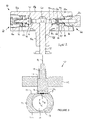
- the high-pressure pump 26 comprises a pumping head 50, shown schematically in Figure 2 , which is arranged to receive a reciprocable pumping plunger or pumping element 52.
- the pump 26 further comprises a drive assembly 100, shown in Figure 3 , for driving reciprocal movement of the pumping element 52 along a pumping axis Q.
- the pumping head 50 comprises a housing 56 that includes a blind bore 58.
- the pumping element 52 is slidably received within the bore 58.
- a pumping chamber 60 at the blind end of the bore 58 is defined in part by the pumping member 52 and in part by the bore 58.
- the pumping head 50 further comprises a spring-biased inlet valve 62 and a spring-biased outlet valve 64.
- a spring-biased inlet valve 62 When the pumping element 52 moves downwards (referred to as a filling stroke or return stroke of the pumping element 52), the volume of the pumping chamber 60 increases, the outlet valve 64 closes, and the inlet valve 62 opens when the pressure differential across it reaches a first predetermined level. Fuel is then admitted to the pumping chamber 60 from a fuel supply port 63, through the inlet valve 62. The fuel supply port 63 is fed with fuel from the inlet metering valve (32 in Figure 1 ).
- the pumping element 52 moves upwards (referred to as a pumping stroke or forward stroke of the pumping element 52), the volume of the pumping chamber 60 decreases, the inlet valve closes 62, and the pressure of fuel in the pumping chamber 60 increases.
- the outlet valve 64 is arranged to open at a second pre-determined pressure. Fuel is then delivered through the outlet valve 64 from the pumping chamber 60 at the second pre-determined pressure, for delivery to the fuel rail 14 through an outlet port 65.
- the second pre-determined pressure at a high level, for example 2000 bar or more, pressurisation of the fuel rail 14 to the desired level can be achieved.
- the pumping head 50 is generally 'T'-shaped, so that the housing 56 comprises a vertically-extending portion 56a and first and second horizontally-extending portions 56b, 56c that extend in opposite directions from the vertically-extending portion 56a.
- the bore 58 extends within the vertically-extending portion 56a of the housing 56, and the inlet and outlet valves 62, 64 are received in the first and second horizontally-extending portions 56b, 56c, respectively.
- a first high-pressure seal 70 is provided to prevent leakage of fuel from the pumping chamber 60 past the inlet valve 62, and a second high-pressure seal 72 is provided to prevent leakage of fuel from the pumping chamber 60 past the outlet valve 64.
- the first horizontally-extending portion 56b of the housing 56 includes an inlet passage 74 that extends laterally from the pumping chamber 60.
- the inlet passage 74 opens into an enlarged-diameter inlet valve bore 76 that houses the inlet valve 62, so that, when the inlet valve 62 is open, fuel can flow from the supply port 63, through the inlet valve 62 and the inlet passage 74 into the pumping chamber 60.
- a first internal shoulder 78 of the housing 56 is defined where the relatively large diameter inlet valve bore 76 meets the relatively small diameter inlet passage 74.
- the inlet valve bore 76 includes an internally-threaded region 76a.
- the inlet valve 62 has an externally-threaded region that engages with the threaded region 76a of the inlet valve bore 76 to secure the inlet valve 62 in the housing 56.
- an end face of the generally cylindrical inlet valve 62 is clamped against the first shoulder 78 of the housing 56 to form the first high-pressure seal 70.
- the outlet valve 86 comprises a generally cylindrical end member 64a, a valve ball 64b, and a spring 64c that acts between the valve ball 64b and the end member 64a.
- An outlet passage 84 extends laterally from the pumping chamber 60 to open into an enlarged-diameter outlet valve bore 86 that houses the end member 64a of the outlet valve 64.
- the outlet passage 84 includes a first portion 84a adjacent to the pumping chamber 60, and a second portion 84b with a larger diameter than the first portion 84a.
- a valve seat 84c for the valve ball 64b is provided in the outlet passage 84, where the first portion 84 meets the second portion 84b.
- outlet valve 64 When the outlet valve 64 is open (i.e. when the valve ball 64b is lifted off the valve seat 84c), fuel can flow from the pumping chamber 60, through the outlet passage 84 and the outlet valve 64 and out of the housing 56 via the outlet port 65.
- a second internal shoulder 88 of the housing 56 is defined where the relatively large diameter outlet valve bore 86 meets the relatively small diameter outlet passage 84.
- the outlet valve bore 86 At its outside end, the outlet valve bore 86 includes an internally-threaded region 86a that engages with an externally-threaded region of the outlet valve 64 to secure the outlet valve 64 in the housing 56.
- an end face of the generally cylindrical outlet valve 64 is clamped against the second shoulder 88 of the housing 56, with sufficient clamping force being applied to ensure that no fuel leaks past the second high-pressure seal 72.
- a further high-pressure seal (not shown) is required to seal the connection between the outlet port 65 and a fuel line (30 in Figure 1 ) that connects the head 50 to the fuel rail (14 in Figure 1 ), in use.
- the drive assembly 100 comprises a housing 102, also known as a cam box, which houses a cylindrical cam 104.
- the housing 102 is only partially shown in Figure 3 .
- the cam 104 is driven in eccentric rotational movement by a drive shaft (not shown in Figure 3 ) that extends through the housing 104, so that the cylinder axis C of the cam 104 describes a circular path around the axis A of the drive shaft (which extends normal to the drawing plane in Figure 3 ) as the drive shaft rotates.
- the path described by the edge of the cam 104 as it rotates is indicated by the dashed line P in Figure 3 .
- the drive shaft has a smaller diameter than the cam 104.
- the cam 104 carries a cam ring or rider 106, which includes a central cylindrical aperture 108 for receiving the cam 104.
- the rider 106 includes a flattened surface region or flat 110, which is arranged to cooperate with a cam follower or tappet 112 that acts as a drive member for the pumping element 52.
- the cam 104 is free to rotate in the aperture 108, so that the orientation of the flat 110 of the rider 106 remains horizontal in use.
- the tappet 112 is guided for reciprocal movement through an opening 114 in the housing 102, and is coupled to the pumping element 52 so that movement of the tappet 112 causes movement of the pumping element 52.
- the tappet 112 includes a flat base surface 116 that is held in sliding contact with the flat 110 of the cam rider 106 by a biasing or return spring 118.
- the housing 102 contains a lubricant (conveniently fuel) that lubricates the sliding interfaces between the tappet 112 and the rider 106 and between the tappet 112 and the wall of the opening 114.
- the cam 104 In operation, as the drive shaft rotates, the cam 104 carries the rider 106 in a path having an upward component, towards the opening 114 in the housing 102. By virtue of the upward component of movement of the rider 106, the tappet 112 is driven upwards by the rider 106, so as to drive the forward stroke of the pumping element (52 in Figure 2 ). Once the cam 104 reaches its uppermost position (top dead centre or TDC), continued rotation of the drive shaft results in the cam 104 carrying the rider 106 in a path having a downward component, away from the opening 114 in the housing 102.
- TDC top dead centre
- the biasing spring 118 keeps the tappet 112 in engagement with the flat 110 of the rider 106, so that the tappet 112 moves downwards and the pumping element (52 in Figure 2 ) is therefore driven by the biasing spring 114 in its return stroke.
- the pumping cycle repeats as the drive shaft continues to rotate.
- Torque spikes of this nature are undesirable, since they can cause damage to the components of the pumping arrangement and the associated drive train.
- the repetitive, cyclical forces to which the components are subjected can give rise to fatigue failures of the components.
- One approach to reducing this problem is to provide one or more further pumping heads, so that the demand for high-pressure fuel can be spread between the heads. The peak torque required by each head is therefore reduced.
- a second pumping head may be mounted diametrically opposite the pumping head 50 shown in Figure 2 .
- a pumping element (not shown) associated with the second pumping head is driven by a tappet (not shown) that cooperates with a second flat 110a provided on the rider 106.
- the first pumping element 52 undergoes its forward stroke
- the second pumping element undergoes its return stroke, and vice versa. Therefore the torque demand is more evenly spread in the pumping cycle.
- Such a multi-head pumping arrangement requires extra space to accommodate the or each additional pumping head.
- additional fuel lines or other suitable connection means must be provided to deliver low-pressure fuel to the additional head and to receive high-pressure fuel from the pumping head. Accordingly, the provision of one or more additional heads adds complexity and cost to the pumping arrangement.
- a pumping head for a high-pressure fuel pump comprises a head housing having a bore, a pumping element slidably received in the bore and arranged for reciprocal linear movement along a pumping axis in alternating forward and return strokes together defining a pumping cycle, and a first pumping chamber and a second pumping chamber, each pumping chamber being defined, in part, by the pumping element, and inlet means for delivering fluid to the first pumping chamber from a source of fluid.
- the pumping head further comprises outlet means for conveying fluid from the second pumping chamber to an outlet of the pumping head, and transfer means for conveying fluid from the first pumping chamber to the second pumping chamber.
- Each forward stroke of the pumping element causes an increase in volume of the first pumping chamber and a decrease in volume of the second pumping chamber, thereby to cause fluid to flow into the first pumping chamber from the inlet means and to cause fluid to flow out of the second pumping chamber to the outlet means.
- Each return stroke of the pumping element causes a decrease in volume of the first pumping chamber and an increase in volume of the second pumping chamber, thereby to cause fluid to flow from the first chamber to the second chamber through the transfer means.
- the pumping head is provided with two pumping chambers, the pressure of fluid is increased both on the forward stroke and on the return stroke of the pumping cycle, thereby increasing the efficiency of the pumping head. Furthermore, when used with a rotary drive mechanism, the peak drive torque required to achieve a given outlet pressure can be reduced, compared to a pumping head with a single pumping chamber. Advantageously, therefore, the risk of damage to the drive mechanism for the pumping element is reduced in the present invention.
- fluid is delivered to the first pumping chamber at a relatively low inlet pressure.
- the decrease in volume of the first pumping chamber during the return stroke preferably causes an increase in fluid pressure to an intermediate pressure.
- the decrease in volume of the second pumping chamber during the forward stroke preferably causes a further increase in fluid pressure to a relatively high outlet pressure.
- the intermediate pressure is preferably at least approximately 25% of the outlet pressure.
- the first pumping chamber may be larger in cross-sectional area in a plane normal to the pumping axis than the second pumping chamber.
- the transfer means preferably comprises a transfer passage in the pumping element.
- the transfer means may comprise a transfer valve arranged to permit fluid flow from the first chamber to the second chamber during the return stroke, and to restrict fluid flow from the second chamber to the first chamber during the forward stroke.
- Relief means for providing communication between the bore and a low-pressure drain may be provided.
- the relief means is remote from the first chamber and the second chamber.
- the relief means comprises a non-return valve to prevent the flow of fluid from the drain into the pumping bore.
- the relief means may comprise a relief chamber defined, in part, by the pumping element and optionally in part by the bore.
- the pumping element comprises a shaft and a collar portion.
- the first chamber may be defined, in part, by a first surface of the collar portion.
- the relief chamber may be defined, in part, by an oppositely-facing second surface of the collar portion.
- the second pumping chamber may be defined, in part, by an end of the pumping element.
- One or more of the first pumping chamber, the second pumping chamber and, when present, the relief chamber may be defined, in part, by the bore of the housing.
- the pumping head may comprise a guide member for the pumping element and a retaining member for retaining the guide member.
- the first pumping chamber may be defined, in part, by the guide member.
- the inlet means may comprise a fluid flow path between the guide member and the retaining member, and the guide member may be engageable with the retaining member to restrict fluid flow through the fluid flow path during the return stroke.
- the inlet means may comprise an inlet passage that opens into the first chamber, and the pumping element may be arranged to occlude the inlet passage to limit flow between the first chamber and the inlet passage during a portion of the pumping cycle.
- the outlet means may comprise an outlet valve, the outlet valve being configured to allow fluid to flow from the second pumping chamber to the outlet during the forward stroke.
- the outlet valve may be configured to allow fluid to flow only when the pressure of fluid in the second pumping chamber reaches a pre-determined outlet pressure.
- the outlet valve is preferably a non-return valve, to prevent the flow of fluid from the outlet into the second pumping chamber during the return stroke.
- the pumping head includes a third pumping chamber comprising an inlet pumping chamber, a first inlet passage for delivering fluid to the inlet pumping chamber from the source of fluid, and a second inlet passage for transferring fluid from the inlet pumping chamber to the first pumping chamber.
- the return stroke of the pumping element causes an increase in volume of the inlet pumping chamber, thereby to cause fluid to flow into the inlet pumping chamber from the first inlet passage.
- the forward stroke of the pumping element causes a decrease in volume of the inlet pumping chamber, thereby to cause fluid to flow from the inlet pumping chamber to the first pumping chamber through the second inlet passage. In this way, the fluid can be increased to a first intermediate pressure in the inlet pumping chamber, then to a second intermediate pressure in the first chamber, and then to the outlet pressure in the second chamber.
- a fuel pump for a fuel injection system comprises a pumping head according to the first aspect of the invention, and a drive mechanism for driving the pumping element of the pumping head in linear reciprocal movement.
- the invention resides in a method for pressurising fluid to a relatively high outlet pressure in a pumping head of a fluid pump.
- the method comprises admitting fluid to the pumping head at a relatively low inlet pressure, pressurising the fluid to an intermediate pressure during a first stage of a pumping cycle, and pressurising the fluid to the relatively high outlet pressure during a second stage of the pumping cycle.
- the force required to pressurise the fluid is distributed over both the first and second stages of the pumping cycle. Accordingly, the peak force required is advantageously lower than if the pressure of the fluid were to be increased from the inlet pressure to the outlet pressure in one pumping operation.
- FIG. 4 shows a pumping head 200 according to a first embodiment of the present invention.
- the pumping head 200 is suitable for use in a high-pressure fuel pump in a fuel injection system.
- the pumping head 200 includes a pumping element or plunger 202 that is driveable in linear reciprocal movement along a pumping axis Q by a drive mechanism (not shown) of the pump.
- the pumping head 200 comprises a generally cylindrical housing 204 having a blind pumping bore 206 that extends upwardly from the lowermost end 204a of the housing 204 and receives the pumping element 202.
- the pumping bore 206 extends coaxially with the pumping axis Q.
- the pumping bore 206 comprises a relatively small diameter upper portion 206a, and a relatively large diameter lower portion 206b.
- An internal shoulder 208 of the pumping bore 206 is defined where the upper and lower portions 206a, 206b meet.
- the pumping element 202 includes a shaft 210 and a collar portion 212 located part-way along the shaft 210.
- An upper end portion 210a of the shaft 210, above the collar portion 212, is slidably received in the relatively small diameter upper portion 206a of the pumping bore 206, and a lower portion 210b of the shaft 210 extends downwards out of the pumping head 200 to cooperate with the drive mechanism (not shown).
- the collar portion 212 has a larger diameter than the shaft 210, and is slidably received in the relatively large diameter lower 206b of the pumping bore 206.
- the pumping bore 206 is closed at the lowermost end 204a of the housing 204 by a sealing arrangement 214 through which the lower portion 210b of the shaft 210 extends.
- the sealing arrangement 214 includes an annular guide member 216 of generally tubular form, a sealing washer 218, and a retaining member 220.
- the guide member 216 includes a central bore 216a for receiving the lower portion 210b of the shaft 210.
- An upper end portion of the guide member 216 is provided with an outwardly-extending flange 216b.
- the sealing washer 218 is located between an upper face of the flange 216b and the lower end 204a of the housing 204.
- the retaining member 220 is of generally tubular form, and includes a bore 220a for receiving the lowermost end 204a of the housing 204.
- the retaining member 220 and the lowermost end 204a of the housing 204 are provided with cooperating threaded regions (not shown), so that the retaining member 220 can be securely engaged with the end 204a of the housing 204 during assembly of the pumping head 200.
- a lower end portion of the retaining member 220 is provided with an inwardly-extending flange 220b, which cooperates with the outwardly-extending flange 216b of the guide member 216. In this way, the guide member 216 is retained by the retaining member 220, and the sealing washer 218 is clamped between the guide member 216 and the lowermost end 204a of the housing 204.
- An annular first pumping chamber 240 of the pumping head 200 is defined by the lowermost face of the collar 212, part of the lower portion 210b of the shaft 210, part of the wall of the lower portion 206a of the pumping bore and the uppermost face of the guide member 216.
- the sealing washer 218 prevents leakage of fluid from the first pumping chamber 240 between the housing 204 and the guide member 216.
- the lower portion 210b of the shaft 210 is a close sliding fit in the bore 216a of the guide member 216, so that leakage from the first pumping chamber 240 between the shaft 210 and the guide member 216 is minimal.
- the upper portion 206b of the pumping bore 206 ends at an end wall 204b of the housing 204.
- a generally cylindrical second pumping chamber 242 is defined by the uppermost end of the pumping element shaft 210, the wall of the upper portion 206b and the end wall 204b of the housing 204.
- the upper portion 201a of the pumping element shaft 210 is a close sliding fit in the upper portion 206b of the pumping bore 206, so that leakage from the second pumping chamber 242 between the shaft 210 and the housing 204 is minimal.
- the housing 204 is provided with a tubular outlet port 244 that is threaded to connect with a high-pressure fluid line (not shown) in use of the pumping head 200.
- An outlet valve 246 is housed within the outlet port 244.
- the outlet valve 246 provides an outlet means that controls the flow of fluid through an outlet passage 248 that extends through the end wall 204b of the housing, between the second pumping chamber 242 and the outlet port 244.
- the outlet valve 246 comprises a valve ball 250 that is engageable with a seating surface 252 formed at the upper end of the outlet passage 248.
- a biasing spring 254 biases the valve ball 250 into engagement with the seating surface 252.
- the biasing spring 254 acts between the valve ball 250 and a cup-shaped outlet valve body 256.
- the outlet valve body 256 is an interference fit in the outlet port 244, and includes an aperture 258 to allow fluid flow through the outlet valve 246 when the valve ball 250 is disengaged from the seating surface 252.
- a transfer passage 260 extends between the first chamber 240 and the second chamber 242, through the pumping element 206, to provide a transfer means for fluid.
- the transfer passage 260 includes a first section 260a that extends inwardly from the outer surface of the pumping element 202, in a direction inclined to the pumping axis Q.
- the first section 260a opens into the first chamber 240 at the corner between the collar portion 212 and the lower shaft portion 210b.
- the first section 260a of the transfer passage 260 meets a second section 260b of the transfer passage 260 that extends in a coaxial direction with respect to the pumping axis Q.
- the second section 260b of the transfer passage 260 in turn, opens into a third section 260c of the transfer passage that has an increased diameter, relative to the first and second sections 260a, 260b.
- the third section 260c of the transfer passage 260 opens into the second pumping chamber 242 at the top end of the pumping element 202.
- a transfer passage valve 262 is housed in the third section 260c of the transfer passage 260, to control the flow of fluid from the first chamber 240 to the second chamber 242 through the transfer passage 260.
- the transfer passage valve 262 is of similar construction to the outlet valve 246, and comprises a valve ball 264 that is engageable with a seating surface 266 formed at the upper end of the third transfer passage section 260c.
- a biasing spring 268 acts between the valve ball 264 and a cup-shaped transfer passage valve body 270 to urge the valve ball 264 into engagement with the seating surface 266.
- the valve body 270 is an interference fit in the third transfer passage section 260c, and includes an aperture 272 to allow fluid flow through the transfer passage valve 262 when the valve ball 264 is disengaged from the seating surface 266.
- a relief chamber 274 of the pumping head 200 is defined by the uppermost face of the collar 212, part of the upper portion 210a of the shaft 210, the wall of the upper portion 206b of the pumping bore 206 and the shoulder 208 of the pumping bore 206.
- a relief port 276 is provided in the wall of the housing 206, and the relief port 276 communicates with the relief chamber 274 by way of a relief passage 278.
- a non-return relief valve 280 is received in the relief chamber 274, to control the flow of fluid from the relief chamber 274 to the relief port 276.
- the relief valve 280 is similar in construction to the outlet valve 246 and the transfer passage valve 262, and comprises a valve ball 282 that engages with a seating surface 284 formed at the end of the relief passage 278, a biasing spring 284, and a valve body 286 having an aperture 288.
- the components of the relief valve 280 are arranged as described above with reference to the outlet valve 246 and the transfer passage valve 262.
- the relief port 276 is connected to a low-pressure drain (such as the internal volume of a pump housing or the fuel tank of a fuel injection system).
- the relief chamber 280 and the relief port 276 are remote from the first chamber 240 and the second chamber 242.
- the relief chamber 274 and the relief port 276 are not in communication with the first chamber 240 or the second chamber 242 by a dedicated fluid flow passage.
- fluid can leak into the relief chamber 274 from both the first chamber 240 and the second chamber 242 along the sliding interfaces between the plunger 202 and the bore 206.
- Fluid is supplied to the pumping head 200 by a supply line (not shown) that communicates with an inlet means comprising an inlet passage 290 that extends through the wall of the housing 204.
- the inlet passage 290 is arranged so that, as the pumping element 202 reciprocates within the pumping bore 206, the inlet passage 290 is either occluded by the collar portion 212 of the pumping element 202 (as shown in Figure 4 ), or is open to allow fluid flow from the inlet passage 290 into the first pumping chamber 240.
- the drive mechanism (not shown) drives the pumping element 202 in reciprocal linear movement.
- the pumping element 202 moves between a bottom dead centre (BDC) position, in which the pumping element 202 is at its furthest downward extent of travel in the pumping bore 206, and a top dead centre (TDC) position, in which the pumping element 202 is at its furthest upward extent of travel in the pumping bore 206.
- BDC bottom dead centre
- TDC top dead centre
- Movement of the pumping element 202 from the BDC position to the TDC position is known as a forward stroke of the pumping element 202
- movement of the pumping element 202 from the TDC position to the BDC position is known as a return stroke of the pumping element 202.
- the forward and return strokes of the pumping element 202 together define a pumping cycle.
- the transfer passage valve 262 acts as a non-return valve to prevent fluid from flowing from the second pumping chamber 242 into the first pumping chamber 240 through the transfer passage 260.
- the pressure of fluid in the first pumping chamber 240 decreases as the volume of the first pumping chamber 240 increases.
- the inlet passage 290 is occluded by the collar portion 212 of the pumping element 202. Then, as the pumping element 202 continues to move upwards, the collar portion 212 moves past the opening of the passage 290 to allow fluid to flow from the inlet passage 290 into the first pumping chamber 240 to fill the first pumping chamber 240 with fluid at relatively low pressure, corresponding to the pressure at which fluid is supplied to the inlet passage 290.
- the pressure of fluid in the second pumping chamber 242 increases as the volume of the second pumping chamber 242 decreases.
- the pressure in the second pumping chamber 242 continues to rise as the pumping element 202 moves upwards within the pumping bore 206.
- the outlet valve 246 is configured such the ball 250 moves away from its seating surface 252, against the action of the biasing spring 254, when the fluid pressure difference across the outlet valve 246 reaches a predetermined value. In other words, the outlet valve 246 opens when the fluid pressure in the second pumping chamber 242 reaches a sufficiently high pressure. Once the outlet valve 246 opens, fluid is ejected from the second pumping chamber 242 through the outlet port 244 at relatively high pressure.
- the outlet valve 246 closes and the return stroke of the pumping element 202 begins.
- the volume of the first pumping chamber 240 decreases, and the volume of the second pumping chamber 242 increases.
- the transfer passage valve 262 is configured such that, when the pressure of fluid in the first chamber 240 exceeds the pressure of the fluid in the second chamber 242 by a pre-determined amount, the transfer passage valve 262 opens to allow fluid to flow from the first chamber 240 to the second chamber through the transfer passage 260.
- the inlet passage 290 remains open so some fluid may flow from the first pumping chamber 240 back out of the inlet passage 290.
- the collar portion 212 of the pumping element 202 occludes the inlet passage 290 to restrict further flow through the inlet passage 290.
- the fluid in the first pumping chamber 240 becomes pressurised, and is forced through the transfer passage 260 into the second pumping chamber 242.
- the volume change that occurs in the first chamber 240 during a given linear displacement of the pumping element 202 is greater than the volume change that occurs in the second chamber 242 during the same linear displacement.
- the fluid pressure rises to an intermediate level as it passes from the first pumping chamber 240 to the second pumping chamber 242 during the return stroke.
- the pumping cycle continues with another forward stroke, in which the first pumping chamber 240 is re-filled with fluid from the inlet passage 290, and the fluid in the second pumping chamber 242 is expelled at high pressure through the outlet port 244.
- Fluid is therefore pumped through the pumping head 200 from the inlet passage 290 to the outlet port 244 in three consecutive pumping strokes of the pumping element, namely a first forward stroke, a return stroke, and a second forward stroke, as will now be described.
- a quantity of fluid is drawn into the first pumping chamber 240 during the first forward stroke of the pumping element 202.
- the quantity of fluid is pressurised to an intermediate pressure in the first pumping chamber 240 and is transferred to the second pumping chamber 242.
- the fluid in the second pumping chamber 242 is already at an elevated intermediate pressure, which is lower than the ultimate outlet pressure, but which is substantially higher than the inlet pressure.
- the fluid in the second pumping chamber 242 is pressurised further to a relatively high outlet pressure, and is delivered from the pumping head 200 through the outlet port 244 at the outlet pressure.
- the magnitude of the volume change that occurs in the first chamber 240 during the forward and return strokes of the pumping element 202 is greater than the magnitude of the volume change that occurs in the second chamber 242 during the forward and return strokes.
- the cross-sectional area of the first chamber 240 in a plane normal to the pumping axis Q is greater than the cross-sectional area of the second chamber 242, so that the volume swept by the pumping element 202 in use is greater in the first chamber 240 than in the second chamber 242.
- the linear displacement of the pumping element 202 in each chamber is the same, the increase in fuel pressure that occurs in the first chamber 240 is less than the increase in fluid pressure that occurs in the second chamber 242, in use.
- the pumping head 200 is arranged so that the pressure of fluid is increased both on the forward stroke and on the return stroke of the pumping cycle.
- the torque demand on the drive mechanism, and on the drive train that drives the drive mechanism, is therefore split between the forward and return strokes, and torque spikes of lower magnitude occur than would be the case if the pressure of the fluid were elevated to the outlet pressure during only the forward stroke of the pumping element 202.
- the second pumping chamber 242 can be reduced in volume compared to the single pumping chamber of a known pumping head, such as that shown in Figure 2 , whilst achieving the same delivery volume. Accordingly, the maximum torque required to pressurise the fuel to the same outlet pressure is lower in the pumping head of the invention.
- the intermediate fluid pressure to which the fluid is elevated during the return stroke of the pumping element 202 depends on, amongst other factors, the cross-sectional area of the first pumping chamber 240, the stroke of the pumping element 202, the force of the biasing spring 268 of the transfer passage valve 262.
- the pumping head 200 is arranged so that, during the return stroke of the pumping element 202, the pressure of the fluid that reaches the second pumping chamber 242 is increased to an intermediate pressure that is approximately 25% of the outlet pressure from the pumping head 200.
- the pumping head 200 could be designed so that the intermediate pressure is higher or lower than 25% of the outlet pressure.
- fluid may leak between the pumping element 202 and the pumping bore 206 into the relief chamber 274.
- fluid may leak from the second pumping chamber 242 past the upper portion 210a of the pumping element shaft 210 into the relief chamber 274, and during the return stroke of the pumping element 202, fluid may leak from the first pumping chamber past the collar portion 212 of the pumping element 202 into the relief chamber 274.
- Fluid that leaks into the relief chamber 274 can flow out of the pumping head 200 through the relief valve 280, thereby preventing a build-up of leakage fluid in the pumping head 200 that could otherwise impair its operation.
- the relief valve 280 acts as a non-return valve to prevent fluid being drawn into the relief chamber 274 from the low-pressure drain.
- a pumping head 300 according to a second embodiment of the invention will now be described with reference to Figure 5 which is a cross-sectional view of part of the pumping head 300 taken on a vertical plane containing the pumping axis Q, and to Figure 6 , which is a cross-section taken on an inclined plane, along line R-S in Figure 5 .
- the pumping head 300 of the second embodiment differs from the pumping head 200 of the first embodiment, shown in Figure 4 , in the arrangement of the inlet means and in the configuration of the sealing arrangement that closes the lowermost end of the pumping bore, and only these differences will be described in detail below.
- the pumping heads 200, 300 of the first and second embodiments of the invention are otherwise identical. Like reference numerals are therefore used in Figures 5 and 6 to denote like components already described with reference to Figure 4 , and reference should be made to the foregoing description where appropriate for an explanation of the features of the pumping head 300 of the second embodiment that are not referred to again below.
- the pumping bore 206 is closed at the lowermost end 204a of the housing 204 by a inlet arrangement 314 that provides an inlet means to supply fluid to the first pumping chamber 240. No separate inlet passage to the pumping bore 204 need be provided.
- the inlet arrangement 314 comprises an annular guide member 316 of generally tubular form, and a retaining member 320.
- the guide member 316 includes a central bore 316a in which the lower portion 210b of the pumping element shaft 210 is slidably received.
- An upper portion of the guide member 316 is provided with an outwardly-extending flange 316b.
- the upper surface of the flange 316b is provided with a plurality of channels 316c that extend radially inwards from the periphery of the flange 316b. The channels 316c stop short of the bore 316a.
- the retaining member 320 is of similar form to the retaining member 220 of the pumping head 200 of the first embodiment of the invention.
- the retaining member 320 is therefore of generally tubular form and includes a bore 320a for receiving the lowermost end 204a of the housing 204.
- the retaining member 320 and the lowermost end 204a of the housing 204 are provided with cooperating threaded regions (not shown). When assembled, an upper end 320c of the retaining member 320 abuts a shoulder 204c of the housing 204.
- a lower end portion of the retaining member 320 is provided with an inwardly-extending flange 320b.
- the guide member 316 is a clearance fit within the flange 320b, and the outer diameter of the flange 316b of the guide member 316 is less than the inside diameter of the retaining member 320.
- the flange 316a of the slide member has a thickness that is less than the gap between the lowermost end 204a of the housing 204 and the uppermost face of the flange 320b of the retaining member 320.
- the guide member 316 can move in a direction parallel to the pumping axis Q within the gap between the lowermost end 204a of the housing 204 and the flange 320b of the retaining member.
- the guide member 316 cooperates with the retaining member 320 and the housing 204 to act as an inlet disc valve for the pumping head 300, as will now be described.
- the decreasing pressure in the first pumping chamber 240 causes the guide member 316 to move upwards into a first position.
- the upper surface of the flange 316b of the guide member 316 abuts the lowermost end 204a of the housing 204, leaving a gap between the lower surface of the flange 316b of the guide member 316 and the upper surface of the flange 320b of the retaining member 320.
- fluid can flow into the first pumping chamber 240 via the clearances between the guide member 316 and the retaining member 320, and through the channels 316c in the upper surface of the flange 320b that provide a flow path for fluid past the lowermost end 204a of the housing 204.
- the increasing pressure in the first pumping chamber 240 causes the guide member 316 to move downwards into a second position.
- the flange 316b of the guide member 316 seats against the flange 320b of the retaining member 320, thereby preventing fluid flow out of the first pumping chamber 240 through the inlet arrangement 314.
- the pumping head 300 shown in Figures 5 and 6 may be used where the fluid to be pumped is supplied to the pumping head 300 by way of an internal volume defined by a housing (not shown) that houses the drive mechanism for the pumping element 204.
- the fluid to be pumped may comprise a lubricating fluid, such as diesel fuel, that lubricates the drive mechanism.
- any suitable inlet means may be provided for supplying fluid to the first pumping chamber.
- an inlet passage that is occluded by the port (as shown in Figure 4 ) or a disc-valve arrangement (as shown in Figures 5 and 6 ) an inlet passage that is always in communication with the first pumping chamber may be provided, and an external check valve may be used to prevent back-flow into the inlet passage during the return stroke of the pumping element.
- an inlet metering valve may be provided to regulate the supply of fluid to the pumping head through the inlet means.
- the inlet means may include one or more passages in the pumping element.
- outlet valve arrangement could be provided in place of the ball-type outlet valve described above.
- the outlet valve arrangement may be integral with the pumping head, as described above, or may be housed separately from the pumping head with a high-pressure line to convey fluid from the pumping head to the outlet valve arrangement.
- any suitable transfer passage valve arrangement could be provided.
- a transfer passage arrangement having one or more ports that are occluded by the pumping element during part of the pumping cycle could be used to effect transfer of fluid from the first chamber to the second chamber.
- any suitable means may be used to transfer fluid from the first pumping chamber to the second pumping chamber, in use.
- a transfer passage in the pumping element instead of or in addition to a transfer passage in the pumping element, one or more transfer passages that extend within a wall of the housing could be provided.
- Pumping heads according to the invention with alternative configurations of the pumping element and pumping bore can be envisaged.
- the upper portion of the pumping bore and the upper portion of the pumping element shaft could be omitted, and the first chamber could be provided in the space occupied by the third chamber in the above-described embodiments.
- the third chamber serves only to provide a path for leakage fluid to return to drain.
- the third chamber could instead be used as an additional pumping chamber of the pumping head.
- the fluid could be pressurised to a first intermediate pressure in a first pumping chamber during one stroke of the pumping element, then pressurised to a second, higher intermediate pressure in the second pumping chamber during the next stroke, and then pressurised to the outlet pressure in the third pumping chamber during the next stroke.
- the third chamber comprises an inlet pumping chamber.
- the inlet passage is arranged to deliver fluid to the inlet pumping chamber.
- a second inlet passage is provided to transfer fluid from the inlet pumping chamber to the first pumping chamber.
- the second inlet passage may, for example, extend through the collar portion of the pumping element, and may include a non-return valve to prevent back flow from the first chamber into the inlet pumping chamber.
- a known drive mechanism such as that described with reference to Figure 3 may be used to drive the reciprocal movement of the pumping element, in which case the force available to drive the return stroke of the plunger depends on the strength of the return spring of the drive mechanism.
- a drive mechanism capable of driving the return stroke of the plunger by means other than a return spring may be used.
- the pumping head of the present invention is not limited to use in a fuel injection system, but would be suitable for any application in which a high-pressure pumping head with good reliability and a simple design is desirable.
Landscapes
- Engineering & Computer Science (AREA)
- Mechanical Engineering (AREA)
- General Engineering & Computer Science (AREA)
- Reciprocating Pumps (AREA)
- Fuel-Injection Apparatus (AREA)
- Details Of Reciprocating Pumps (AREA)
Abstract
Description
- This invention relates to a pumping head for a fluid pump. In particular, but not exclusively, the invention relates to a pumping head suitable for use in a high-pressure fuel pump of a fuel injection system for an internal combustion engine.
-
Figure 1 of the accompanying drawings is a schematic diagram of a conventional fuel injection system 10 for an internal combustion engine. - The fuel injection system 10 comprises a plurality of fuel injectors 12. Each injector 12 is arranged to deliver an atomised spray of high-pressure fuel to a respective combustion chamber (not shown) of the engine. The injectors 12 receive fuel at high pressure from an accumulator volume or rail 14, by way of high-
pressure supply lines 16. The rail 14 comprises a reservoir for high-pressure fuel. - Delivery of fuel from the injectors 12 is controlled by an
electronic control unit 18. When a fuel injection from one of the injectors 12 is required, theelectronic control unit 18 sends an actuation signal to the injector 12, which causes actuation of a delivery valve (not shown) of the injector 12. - Fuel is pumped to the rail 14 from a storage tank 20 by a
fuel pump assembly 22. Thefuel pump assembly 22 includes a low-pressure transfer pump 24, which serves to convey fuel from the tank 20 to thepump assembly 22, and a high-pressure pump 26 which elevates the pressure of the fuel to the injection pressure, typically of the order of 2000 bar. Fuel is conveyed from the tank 20 to thepump assembly 22 by way of a low-pressure fuel line 28, and from thepump assembly 22 to the rail by way of a high-pressure fuel line 30. - An
inlet metering valve 32, under the control of theengine control unit 18, is provided between thetransfer pump 24 and the high-pressure pump 26 of thepump assembly 22. Theinlet metering valve 32 determines how much fuel reaches the high-pressure pump 26, for subsequent pressurisation and delivery to the rail 14. The fuel pressure in the rail 14 is regulated to a target value by theelectronic control unit 18. A pressure-limitingvalve 36 and return line 38 prevent the rail pressure exceeding a pre-determined acceptable level. - The high-
pressure pump 26 comprises apumping head 50, shown schematically inFigure 2 , which is arranged to receive a reciprocable pumping plunger orpumping element 52. Thepump 26 further comprises adrive assembly 100, shown inFigure 3 , for driving reciprocal movement of thepumping element 52 along a pumping axis Q. - The pumping
head 50 comprises ahousing 56 that includes ablind bore 58. The pumpingelement 52 is slidably received within thebore 58. Apumping chamber 60 at the blind end of thebore 58 is defined in part by the pumpingmember 52 and in part by thebore 58. As thepumping element 52 is driven in reciprocal linear motion along the pumping axis Q by the drive assembly, the volume of thepumping chamber 60, and hence the pressure in thepumping chamber 60, increases and decreases accordingly. - The pumping
head 50 further comprises a spring-biased inlet valve 62 and a spring-biased outlet valve 64. When thepumping element 52 moves downwards (referred to as a filling stroke or return stroke of the pumping element 52), the volume of thepumping chamber 60 increases, theoutlet valve 64 closes, and theinlet valve 62 opens when the pressure differential across it reaches a first predetermined level. Fuel is then admitted to thepumping chamber 60 from afuel supply port 63, through theinlet valve 62. Thefuel supply port 63 is fed with fuel from the inlet metering valve (32 inFigure 1 ). - When the pumping
element 52 moves upwards (referred to as a pumping stroke or forward stroke of the pumping element 52), the volume of thepumping chamber 60 decreases, the inlet valve closes 62, and the pressure of fuel in thepumping chamber 60 increases. Theoutlet valve 64 is arranged to open at a second pre-determined pressure. Fuel is then delivered through theoutlet valve 64 from thepumping chamber 60 at the second pre-determined pressure, for delivery to the fuel rail 14 through anoutlet port 65. By setting the second pre-determined pressure at a high level, for example 2000 bar or more, pressurisation of the fuel rail 14 to the desired level can be achieved. - The pumping
head 50 is generally 'T'-shaped, so that thehousing 56 comprises a vertically-extendingportion 56a and first and second horizontally-extending portions 56b, 56c that extend in opposite directions from the vertically-extendingportion 56a. Thebore 58 extends within the vertically-extendingportion 56a of thehousing 56, and the inlet andoutlet valves - A first high-
pressure seal 70 is provided to prevent leakage of fuel from thepumping chamber 60 past theinlet valve 62, and a second high-pressure seal 72 is provided to prevent leakage of fuel from thepumping chamber 60 past theoutlet valve 64. - The first horizontally-extending portion 56b of the
housing 56 includes aninlet passage 74 that extends laterally from thepumping chamber 60. Theinlet passage 74 opens into an enlarged-diameter inlet valve bore 76 that houses theinlet valve 62, so that, when theinlet valve 62 is open, fuel can flow from thesupply port 63, through theinlet valve 62 and theinlet passage 74 into thepumping chamber 60. A firstinternal shoulder 78 of thehousing 56 is defined where the relatively large diameterinlet valve bore 76 meets the relatively smalldiameter inlet passage 74. - At its outside end, the
inlet valve bore 76 includes an internally-threadedregion 76a. Theinlet valve 62 has an externally-threaded region that engages with the threadedregion 76a of the inlet valve bore 76 to secure theinlet valve 62 in thehousing 56. In use, an end face of the generallycylindrical inlet valve 62 is clamped against thefirst shoulder 78 of thehousing 56 to form the first high-pressure seal 70. - A similar arrangement is present in the second horizontally-extending portion 56c of the
housing 56. Theoutlet valve 86 comprises a generallycylindrical end member 64a, a valve ball 64b, and a spring 64c that acts between the valve ball 64b and theend member 64a. Anoutlet passage 84 extends laterally from thepumping chamber 60 to open into an enlarged-diameteroutlet valve bore 86 that houses theend member 64a of theoutlet valve 64. Theoutlet passage 84 includes a first portion 84a adjacent to thepumping chamber 60, and a second portion 84b with a larger diameter than the first portion 84a. A valve seat 84c for the valve ball 64b is provided in theoutlet passage 84, where thefirst portion 84 meets the second portion 84b. - When the
outlet valve 64 is open (i.e. when the valve ball 64b is lifted off the valve seat 84c), fuel can flow from thepumping chamber 60, through theoutlet passage 84 and theoutlet valve 64 and out of thehousing 56 via theoutlet port 65. A secondinternal shoulder 88 of thehousing 56 is defined where the relatively large diameteroutlet valve bore 86 meets the relatively smalldiameter outlet passage 84. At its outside end, theoutlet valve bore 86 includes an internally-threaded region 86a that engages with an externally-threaded region of theoutlet valve 64 to secure theoutlet valve 64 in thehousing 56. - In use, an end face of the generally
cylindrical outlet valve 64 is clamped against thesecond shoulder 88 of thehousing 56, with sufficient clamping force being applied to ensure that no fuel leaks past the second high-pressure seal 72. A further high-pressure seal (not shown) is required to seal the connection between theoutlet port 65 and a fuel line (30 inFigure 1 ) that connects thehead 50 to the fuel rail (14 inFigure 1 ), in use. - Referring to
Figure 3 , thedrive assembly 100 comprises ahousing 102, also known as a cam box, which houses acylindrical cam 104. Thehousing 102 is only partially shown inFigure 3 . Thecam 104 is driven in eccentric rotational movement by a drive shaft (not shown inFigure 3 ) that extends through thehousing 104, so that the cylinder axis C of thecam 104 describes a circular path around the axis A of the drive shaft (which extends normal to the drawing plane inFigure 3 ) as the drive shaft rotates. The path described by the edge of thecam 104 as it rotates is indicated by the dashed line P inFigure 3 . The drive shaft has a smaller diameter than thecam 104. - The
cam 104 carries a cam ring orrider 106, which includes a centralcylindrical aperture 108 for receiving thecam 104. Therider 106 includes a flattened surface region or flat 110, which is arranged to cooperate with a cam follower or tappet 112 that acts as a drive member for thepumping element 52. Thecam 104 is free to rotate in theaperture 108, so that the orientation of the flat 110 of therider 106 remains horizontal in use. - The
tappet 112 is guided for reciprocal movement through anopening 114 in thehousing 102, and is coupled to thepumping element 52 so that movement of thetappet 112 causes movement of thepumping element 52. - The
tappet 112 includes aflat base surface 116 that is held in sliding contact with the flat 110 of thecam rider 106 by a biasing orreturn spring 118. Thehousing 102 contains a lubricant (conveniently fuel) that lubricates the sliding interfaces between thetappet 112 and therider 106 and between thetappet 112 and the wall of theopening 114. - In operation, as the drive shaft rotates, the
cam 104 carries therider 106 in a path having an upward component, towards the opening 114 in thehousing 102. By virtue of the upward component of movement of therider 106, thetappet 112 is driven upwards by therider 106, so as to drive the forward stroke of the pumping element (52 inFigure 2 ). Once thecam 104 reaches its uppermost position (top dead centre or TDC), continued rotation of the drive shaft results in thecam 104 carrying therider 106 in a path having a downward component, away from theopening 114 in thehousing 102. The biasingspring 118 keeps thetappet 112 in engagement with the flat 110 of therider 106, so that thetappet 112 moves downwards and the pumping element (52 inFigure 2 ) is therefore driven by the biasingspring 114 in its return stroke. The pumping cycle repeats as the drive shaft continues to rotate. - One disadvantage of the pumping arrangement shown in
Figures 2 and 3 is that only the forward stroke part of the pumping cycle is used to increase the pressure of fuel in thepumping chamber 60. The reverse stroke part of the pumping cycle is used only to re-fill thepumping chamber 60 with low-pressure fuel. Accordingly, the torque required to turn the drive shaft of the pump, and so the torque demanded from the engine, is substantially higher during the forward stroke than during the return stroke, giving rise to a torque peak or spike. - Torque spikes of this nature are undesirable, since they can cause damage to the components of the pumping arrangement and the associated drive train. In particular, the repetitive, cyclical forces to which the components are subjected can give rise to fatigue failures of the components. As pumping heads are designed for increasingly high pumping pressures to meet the demands of modern emissions legislation, correspondingly higher torque spikes occur, which increases the problem.
- One approach to reducing this problem is to provide one or more further pumping heads, so that the demand for high-pressure fuel can be spread between the heads. The peak torque required by each head is therefore reduced.
- For example, a second pumping head (not shown) may be mounted diametrically opposite the pumping
head 50 shown inFigure 2 . In this case, a pumping element (not shown) associated with the second pumping head is driven by a tappet (not shown) that cooperates with a second flat 110a provided on therider 106. As thefirst pumping element 52 undergoes its forward stroke, the second pumping element undergoes its return stroke, and vice versa. Therefore the torque demand is more evenly spread in the pumping cycle. - Such a multi-head pumping arrangement, however, requires extra space to accommodate the or each additional pumping head. Furthermore, additional fuel lines or other suitable connection means must be provided to deliver low-pressure fuel to the additional head and to receive high-pressure fuel from the pumping head. Accordingly, the provision of one or more additional heads adds complexity and cost to the pumping arrangement.
- Against this background, it would be desirable to provide a pumping head that addresses or overcomes the problems of the prior art.
- According to a first aspect of the invention, a pumping head for a high-pressure fuel pump is provided. The pumping head comprises a head housing having a bore, a pumping element slidably received in the bore and arranged for reciprocal linear movement along a pumping axis in alternating forward and return strokes together defining a pumping cycle, and a first pumping chamber and a second pumping chamber, each pumping chamber being defined, in part, by the pumping element, and inlet means for delivering fluid to the first pumping chamber from a source of fluid.
- The pumping head further comprises outlet means for conveying fluid from the second pumping chamber to an outlet of the pumping head, and transfer means for conveying fluid from the first pumping chamber to the second pumping chamber.
- Each forward stroke of the pumping element causes an increase in volume of the first pumping chamber and a decrease in volume of the second pumping chamber, thereby to cause fluid to flow into the first pumping chamber from the inlet means and to cause fluid to flow out of the second pumping chamber to the outlet means. Each return stroke of the pumping element causes a decrease in volume of the first pumping chamber and an increase in volume of the second pumping chamber, thereby to cause fluid to flow from the first chamber to the second chamber through the transfer means.
- Because the pumping head is provided with two pumping chambers, the pressure of fluid is increased both on the forward stroke and on the return stroke of the pumping cycle, thereby increasing the efficiency of the pumping head. Furthermore, when used with a rotary drive mechanism, the peak drive torque required to achieve a given outlet pressure can be reduced, compared to a pumping head with a single pumping chamber. Advantageously, therefore, the risk of damage to the drive mechanism for the pumping element is reduced in the present invention.
- In one embodiment, fluid is delivered to the first pumping chamber at a relatively low inlet pressure. The decrease in volume of the first pumping chamber during the return stroke preferably causes an increase in fluid pressure to an intermediate pressure. The decrease in volume of the second pumping chamber during the forward stroke preferably causes a further increase in fluid pressure to a relatively high outlet pressure.
- By first pressurising the fluid to an intermediate pressure before subsequently pressurising the fluid to a relatively high outlet pressure, the force required to drive the pumping element, and therefore the torque required by a rotary drive mechanism, is reduced during the forward stroke. The intermediate pressure is preferably at least approximately 25% of the outlet pressure.
- The first pumping chamber may be larger in cross-sectional area in a plane normal to the pumping axis than the second pumping chamber.
- The transfer means preferably comprises a transfer passage in the pumping element. Alternatively, or in addition, the transfer means may comprise a transfer valve arranged to permit fluid flow from the first chamber to the second chamber during the return stroke, and to restrict fluid flow from the second chamber to the first chamber during the forward stroke.
- Relief means for providing communication between the bore and a low-pressure drain may be provided. The relief means is remote from the first chamber and the second chamber. By providing relief means, any internal leakage flows of fluid within the pumping head can be exhausted from the pumping head to the drain, thereby preventing a build-up of leakage fluid in the pumping head.
- In one example, the relief means comprises a non-return valve to prevent the flow of fluid from the drain into the pumping bore. Alternatively, or in addition, the relief means may comprise a relief chamber defined, in part, by the pumping element and optionally in part by the bore.
- In one embodiment of the pumping head, the pumping element comprises a shaft and a collar portion. The first chamber may be defined, in part, by a first surface of the collar portion. When present, the relief chamber may be defined, in part, by an oppositely-facing second surface of the collar portion.
- The second pumping chamber may be defined, in part, by an end of the pumping element. One or more of the first pumping chamber, the second pumping chamber and, when present, the relief chamber may be defined, in part, by the bore of the housing.
- The pumping head may comprise a guide member for the pumping element and a retaining member for retaining the guide member. The first pumping chamber may be defined, in part, by the guide member.
- When a guide member is present, the inlet means may comprise a fluid flow path between the guide member and the retaining member, and the guide member may be engageable with the retaining member to restrict fluid flow through the fluid flow path during the return stroke. Alternatively, the inlet means may comprise an inlet passage that opens into the first chamber, and the pumping element may be arranged to occlude the inlet passage to limit flow between the first chamber and the inlet passage during a portion of the pumping cycle.
- The outlet means may comprise an outlet valve, the outlet valve being configured to allow fluid to flow from the second pumping chamber to the outlet during the forward stroke. The outlet valve may be configured to allow fluid to flow only when the pressure of fluid in the second pumping chamber reaches a pre-determined outlet pressure. The outlet valve is preferably a non-return valve, to prevent the flow of fluid from the outlet into the second pumping chamber during the return stroke.
- In one embodiment of the invention, the pumping head includes a third pumping chamber comprising an inlet pumping chamber, a first inlet passage for delivering fluid to the inlet pumping chamber from the source of fluid, and a second inlet passage for transferring fluid from the inlet pumping chamber to the first pumping chamber. The return stroke of the pumping element causes an increase in volume of the inlet pumping chamber, thereby to cause fluid to flow into the inlet pumping chamber from the first inlet passage. The forward stroke of the pumping element causes a decrease in volume of the inlet pumping chamber, thereby to cause fluid to flow from the inlet pumping chamber to the first pumping chamber through the second inlet passage. In this way, the fluid can be increased to a first intermediate pressure in the inlet pumping chamber, then to a second intermediate pressure in the first chamber, and then to the outlet pressure in the second chamber.
- In a second aspect of the invention, a fuel pump for a fuel injection system is provided. The fuel pump comprises a pumping head according to the first aspect of the invention, and a drive mechanism for driving the pumping element of the pumping head in linear reciprocal movement.
- From a third aspect, the invention resides in a method for pressurising fluid to a relatively high outlet pressure in a pumping head of a fluid pump. The method comprises admitting fluid to the pumping head at a relatively low inlet pressure, pressurising the fluid to an intermediate pressure during a first stage of a pumping cycle, and pressurising the fluid to the relatively high outlet pressure during a second stage of the pumping cycle.
- By pressurising the fluid first to an intermediate pressure and then further to a relatively high outlet pressure, the force required to pressurise the fluid is distributed over both the first and second stages of the pumping cycle. Accordingly, the peak force required is advantageously lower than if the pressure of the fluid were to be increased from the inlet pressure to the outlet pressure in one pumping operation.
- Preferred and/or optional features of each aspect of the invention may also be used, alone or in appropriate combination, with the other aspects of the invention also.
-
-
Figure 1 of the accompanying drawings, which has been referred to above, is a schematic diagram of a conventional fuel injection system of an internal combustion engine having a conventional high-pressure fuel pump. -
Figures 2 and 3 , which have also been referred to above, are schematic cross-sectional views of a pumping head and a drive assembly, respectively, of a conventional high-pressure fuel pump for use in the fuel injection system ofFigure 1 . - The present invention will now be described, by way of example only, with reference to the remaining accompanying drawings, in which like reference numerals are used for like features, and in which:
-
Figure 4 is a cross-sectional view of a pumping head according to the invention; -
Figure 5 is a cross-sectional view of part of another pumping head according to the invention; and -
Figure 6 is an inclined sectional view of the pumping head ofFigure 5 , sectioned on line R-S. - Throughout this description, terms such as 'upper', 'lower' and so on relate to the orientation of the components as shown in the accompanying drawings and are used for ease or reference only. It should be understood that the invention could be used in any suitable orientation.
-
Figure 4 shows apumping head 200 according to a first embodiment of the present invention. The pumpinghead 200 is suitable for use in a high-pressure fuel pump in a fuel injection system. The pumpinghead 200 includes a pumping element orplunger 202 that is driveable in linear reciprocal movement along a pumping axis Q by a drive mechanism (not shown) of the pump. - The pumping
head 200 comprises a generallycylindrical housing 204 having a blind pumping bore 206 that extends upwardly from thelowermost end 204a of thehousing 204 and receives thepumping element 202. The pumping bore 206 extends coaxially with the pumping axis Q. - The pumping bore 206 comprises a relatively small diameter upper portion 206a, and a relatively large diameter
lower portion 206b. Aninternal shoulder 208 of the pumping bore 206 is defined where the upper andlower portions 206a, 206b meet. - The
pumping element 202 includes ashaft 210 and acollar portion 212 located part-way along theshaft 210. Anupper end portion 210a of theshaft 210, above thecollar portion 212, is slidably received in the relatively small diameter upper portion 206a of the pumping bore 206, and a lower portion 210b of theshaft 210 extends downwards out of thepumping head 200 to cooperate with the drive mechanism (not shown). Thecollar portion 212 has a larger diameter than theshaft 210, and is slidably received in the relatively large diameter lower 206b of the pumping bore 206. - The pumping bore 206 is closed at the
lowermost end 204a of thehousing 204 by a sealingarrangement 214 through which the lower portion 210b of theshaft 210 extends. The sealingarrangement 214 includes anannular guide member 216 of generally tubular form, a sealingwasher 218, and a retainingmember 220. - The
guide member 216 includes a central bore 216a for receiving the lower portion 210b of theshaft 210. An upper end portion of theguide member 216 is provided with an outwardly-extending flange 216b. The sealingwasher 218 is located between an upper face of the flange 216b and thelower end 204a of thehousing 204. - The retaining
member 220 is of generally tubular form, and includes a bore 220a for receiving thelowermost end 204a of thehousing 204. The retainingmember 220 and thelowermost end 204a of thehousing 204 are provided with cooperating threaded regions (not shown), so that the retainingmember 220 can be securely engaged with theend 204a of thehousing 204 during assembly of thepumping head 200. - A lower end portion of the retaining
member 220 is provided with an inwardly-extendingflange 220b, which cooperates with the outwardly-extending flange 216b of theguide member 216. In this way, theguide member 216 is retained by the retainingmember 220, and the sealingwasher 218 is clamped between theguide member 216 and thelowermost end 204a of thehousing 204. - An annular
first pumping chamber 240 of thepumping head 200 is defined by the lowermost face of thecollar 212, part of the lower portion 210b of theshaft 210, part of the wall of the lower portion 206a of the pumping bore and the uppermost face of theguide member 216. The sealingwasher 218 prevents leakage of fluid from thefirst pumping chamber 240 between thehousing 204 and theguide member 216. The lower portion 210b of theshaft 210 is a close sliding fit in the bore 216a of theguide member 216, so that leakage from thefirst pumping chamber 240 between theshaft 210 and theguide member 216 is minimal. - The
upper portion 206b of the pumping bore 206 ends at an end wall 204b of thehousing 204. A generally cylindricalsecond pumping chamber 242 is defined by the uppermost end of thepumping element shaft 210, the wall of theupper portion 206b and the end wall 204b of thehousing 204. The upper portion 201a of thepumping element shaft 210 is a close sliding fit in theupper portion 206b of the pumping bore 206, so that leakage from thesecond pumping chamber 242 between theshaft 210 and thehousing 204 is minimal. - At its uppermost end, the
housing 204 is provided with a tubular outlet port 244 that is threaded to connect with a high-pressure fluid line (not shown) in use of thepumping head 200. Anoutlet valve 246 is housed within the outlet port 244. - The
outlet valve 246 provides an outlet means that controls the flow of fluid through anoutlet passage 248 that extends through the end wall 204b of the housing, between thesecond pumping chamber 242 and the outlet port 244. Theoutlet valve 246 comprises avalve ball 250 that is engageable with aseating surface 252 formed at the upper end of theoutlet passage 248. A biasingspring 254 biases thevalve ball 250 into engagement with theseating surface 252. The biasingspring 254 acts between thevalve ball 250 and a cup-shapedoutlet valve body 256. Theoutlet valve body 256 is an interference fit in the outlet port 244, and includes anaperture 258 to allow fluid flow through theoutlet valve 246 when thevalve ball 250 is disengaged from theseating surface 252. - A
transfer passage 260 extends between thefirst chamber 240 and thesecond chamber 242, through thepumping element 206, to provide a transfer means for fluid. Thetransfer passage 260 includes a first section 260a that extends inwardly from the outer surface of thepumping element 202, in a direction inclined to the pumping axis Q. The first section 260a opens into thefirst chamber 240 at the corner between thecollar portion 212 and the lower shaft portion 210b. - Inside the
pumping element 202, the first section 260a of thetransfer passage 260 meets a second section 260b of thetransfer passage 260 that extends in a coaxial direction with respect to the pumping axis Q. The second section 260b of thetransfer passage 260, in turn, opens into athird section 260c of the transfer passage that has an increased diameter, relative to the first and second sections 260a, 260b. Thethird section 260c of thetransfer passage 260 opens into thesecond pumping chamber 242 at the top end of thepumping element 202. - A
transfer passage valve 262 is housed in thethird section 260c of thetransfer passage 260, to control the flow of fluid from thefirst chamber 240 to thesecond chamber 242 through thetransfer passage 260. - The
transfer passage valve 262 is of similar construction to theoutlet valve 246, and comprises avalve ball 264 that is engageable with aseating surface 266 formed at the upper end of the thirdtransfer passage section 260c. A biasing spring 268 acts between thevalve ball 264 and a cup-shaped transfer passage valve body 270 to urge thevalve ball 264 into engagement with theseating surface 266. The valve body 270 is an interference fit in the thirdtransfer passage section 260c, and includes an aperture 272 to allow fluid flow through thetransfer passage valve 262 when thevalve ball 264 is disengaged from theseating surface 266. - A
relief chamber 274 of thepumping head 200 is defined by the uppermost face of thecollar 212, part of theupper portion 210a of theshaft 210, the wall of theupper portion 206b of the pumping bore 206 and theshoulder 208 of the pumping bore 206. Arelief port 276 is provided in the wall of thehousing 206, and therelief port 276 communicates with therelief chamber 274 by way of arelief passage 278. - A
non-return relief valve 280 is received in therelief chamber 274, to control the flow of fluid from therelief chamber 274 to therelief port 276. Therelief valve 280 is similar in construction to theoutlet valve 246 and thetransfer passage valve 262, and comprises a valve ball 282 that engages with a seating surface 284 formed at the end of therelief passage 278, a biasing spring 284, and avalve body 286 having an aperture 288. The components of therelief valve 280 are arranged as described above with reference to theoutlet valve 246 and thetransfer passage valve 262. - In use, the
relief port 276 is connected to a low-pressure drain (such as the internal volume of a pump housing or the fuel tank of a fuel injection system). Therelief chamber 280 and therelief port 276 are remote from thefirst chamber 240 and thesecond chamber 242. In other words, therelief chamber 274 and therelief port 276 are not in communication with thefirst chamber 240 or thesecond chamber 242 by a dedicated fluid flow passage. However, fluid can leak into therelief chamber 274 from both thefirst chamber 240 and thesecond chamber 242 along the sliding interfaces between theplunger 202 and thebore 206. - Fluid is supplied to the
pumping head 200 by a supply line (not shown) that communicates with an inlet means comprising aninlet passage 290 that extends through the wall of thehousing 204. Theinlet passage 290 is arranged so that, as thepumping element 202 reciprocates within the pumping bore 206, theinlet passage 290 is either occluded by thecollar portion 212 of the pumping element 202 (as shown inFigure 4 ), or is open to allow fluid flow from theinlet passage 290 into thefirst pumping chamber 240. - Operation of the
pumping head 200 will now be described. As mentioned above, the drive mechanism (not shown) drives thepumping element 202 in reciprocal linear movement. Thepumping element 202 moves between a bottom dead centre (BDC) position, in which thepumping element 202 is at its furthest downward extent of travel in the pumping bore 206, and a top dead centre (TDC) position, in which thepumping element 202 is at its furthest upward extent of travel in the pumping bore 206. - Movement of the
pumping element 202 from the BDC position to the TDC position is known as a forward stroke of thepumping element 202, and movement of thepumping element 202 from the TDC position to the BDC position is known as a return stroke of thepumping element 202. The forward and return strokes of thepumping element 202 together define a pumping cycle. - Starting from the BDC position, as the
pumping element 202 moves upwards within the pumping bore 206 in the forward stroke of the pumping cycle, the volume of thefirst pumping chamber 240 increases, while the volume of thesecond pumping chamber 242 decreases. Thetransfer passage valve 262 acts as a non-return valve to prevent fluid from flowing from thesecond pumping chamber 242 into thefirst pumping chamber 240 through thetransfer passage 260. - During the forward stroke of the
pumping element 202, therefore, the pressure of fluid in thefirst pumping chamber 240 decreases as the volume of thefirst pumping chamber 240 increases. During a first part of the forward stroke, theinlet passage 290 is occluded by thecollar portion 212 of thepumping element 202. Then, as thepumping element 202 continues to move upwards, thecollar portion 212 moves past the opening of thepassage 290 to allow fluid to flow from theinlet passage 290 into thefirst pumping chamber 240 to fill thefirst pumping chamber 240 with fluid at relatively low pressure, corresponding to the pressure at which fluid is supplied to theinlet passage 290. - At the same time, during the forward stoke of the
pumping element 202, the pressure of fluid in thesecond pumping chamber 242 increases as the volume of thesecond pumping chamber 242 decreases. The pressure in thesecond pumping chamber 242 continues to rise as thepumping element 202 moves upwards within the pumping bore 206. - The
outlet valve 246 is configured such theball 250 moves away from itsseating surface 252, against the action of the biasingspring 254, when the fluid pressure difference across theoutlet valve 246 reaches a predetermined value. In other words, theoutlet valve 246 opens when the fluid pressure in thesecond pumping chamber 242 reaches a sufficiently high pressure. Once theoutlet valve 246 opens, fluid is ejected from thesecond pumping chamber 242 through the outlet port 244 at relatively high pressure. - Once the
pumping element 202 reaches the TDC position, theoutlet valve 246 closes and the return stroke of thepumping element 202 begins. During the return stroke, the volume of thefirst pumping chamber 240 decreases, and the volume of thesecond pumping chamber 242 increases. - Accordingly, the pressure of fluid in the
first chamber 240 increases, and the pressure of fluid in thesecond chamber 242 decreases. Thetransfer passage valve 262 is configured such that, when the pressure of fluid in thefirst chamber 240 exceeds the pressure of the fluid in thesecond chamber 242 by a pre-determined amount, thetransfer passage valve 262 opens to allow fluid to flow from thefirst chamber 240 to the second chamber through thetransfer passage 260. - During a first part of the return stroke, the
inlet passage 290 remains open so some fluid may flow from thefirst pumping chamber 240 back out of theinlet passage 290. However, in a second part of the return stroke, thecollar portion 212 of thepumping element 202 occludes theinlet passage 290 to restrict further flow through theinlet passage 290. During this second part of the return stroke, in particular, the fluid in thefirst pumping chamber 240 becomes pressurised, and is forced through thetransfer passage 260 into thesecond pumping chamber 242. - The volume change that occurs in the
first chamber 240 during a given linear displacement of thepumping element 202 is greater than the volume change that occurs in thesecond chamber 242 during the same linear displacement. As a result, the fluid pressure rises to an intermediate level as it passes from thefirst pumping chamber 240 to thesecond pumping chamber 242 during the return stroke. - The pumping cycle continues with another forward stroke, in which the
first pumping chamber 240 is re-filled with fluid from theinlet passage 290, and the fluid in thesecond pumping chamber 242 is expelled at high pressure through the outlet port 244. - Fluid is therefore pumped through the pumping
head 200 from theinlet passage 290 to the outlet port 244 in three consecutive pumping strokes of the pumping element, namely a first forward stroke, a return stroke, and a second forward stroke, as will now be described. - A quantity of fluid is drawn into the
first pumping chamber 240 during the first forward stroke of thepumping element 202. During the subsequent return stroke, the quantity of fluid is pressurised to an intermediate pressure in thefirst pumping chamber 240 and is transferred to thesecond pumping chamber 242. At the end of the return stroke, therefore, the fluid in thesecond pumping chamber 242 is already at an elevated intermediate pressure, which is lower than the ultimate outlet pressure, but which is substantially higher than the inlet pressure. During the second forward stroke, the fluid in thesecond pumping chamber 242 is pressurised further to a relatively high outlet pressure, and is delivered from the pumpinghead 200 through the outlet port 244 at the outlet pressure. - The magnitude of the volume change that occurs in the
first chamber 240 during the forward and return strokes of thepumping element 202 is greater than the magnitude of the volume change that occurs in thesecond chamber 242 during the forward and return strokes. Said another way, the cross-sectional area of thefirst chamber 240 in a plane normal to the pumping axis Q is greater than the cross-sectional area of thesecond chamber 242, so that the volume swept by thepumping element 202 in use is greater in thefirst chamber 240 than in thesecond chamber 242. In this way, although the linear displacement of thepumping element 202 in each chamber is the same, the increase in fuel pressure that occurs in thefirst chamber 240 is less than the increase in fluid pressure that occurs in thesecond chamber 242, in use. - It will be understood that the pumping
head 200 is arranged so that the pressure of fluid is increased both on the forward stroke and on the return stroke of the pumping cycle. The torque demand on the drive mechanism, and on the drive train that drives the drive mechanism, is therefore split between the forward and return strokes, and torque spikes of lower magnitude occur than would be the case if the pressure of the fluid were elevated to the outlet pressure during only the forward stroke of thepumping element 202. - In particular, because the fluid is delivered to the
second pumping chamber 242 at an elevated pressure, thesecond pumping chamber 242 can be reduced in volume compared to the single pumping chamber of a known pumping head, such as that shown inFigure 2 , whilst achieving the same delivery volume. Accordingly, the maximum torque required to pressurise the fuel to the same outlet pressure is lower in the pumping head of the invention. - The intermediate fluid pressure to which the fluid is elevated during the return stroke of the
pumping element 202 depends on, amongst other factors, the cross-sectional area of thefirst pumping chamber 240, the stroke of thepumping element 202, the force of the biasing spring 268 of thetransfer passage valve 262. - Preferably, the pumping
head 200 is arranged so that, during the return stroke of thepumping element 202, the pressure of the fluid that reaches thesecond pumping chamber 242 is increased to an intermediate pressure that is approximately 25% of the outlet pressure from the pumpinghead 200. However, it will be appreciated that the pumpinghead 200 could be designed so that the intermediate pressure is higher or lower than 25% of the outlet pressure. - During operation of the
pumping head 200, fluid may leak between the pumpingelement 202 and the pumping bore 206 into therelief chamber 274. For example, during the forward stroke of thepumping element 202, fluid may leak from thesecond pumping chamber 242 past theupper portion 210a of thepumping element shaft 210 into therelief chamber 274, and during the return stroke of thepumping element 202, fluid may leak from the first pumping chamber past thecollar portion 212 of thepumping element 202 into therelief chamber 274. - Fluid that leaks into the
relief chamber 274 can flow out of thepumping head 200 through therelief valve 280, thereby preventing a build-up of leakage fluid in thepumping head 200 that could otherwise impair its operation. Therelief valve 280 acts as a non-return valve to prevent fluid being drawn into therelief chamber 274 from the low-pressure drain. - A pumping
head 300 according to a second embodiment of the invention will now be described with reference toFigure 5 which is a cross-sectional view of part of thepumping head 300 taken on a vertical plane containing the pumping axis Q, and toFigure 6 , which is a cross-section taken on an inclined plane, along line R-S inFigure 5 . - The pumping
head 300 of the second embodiment differs from the pumpinghead 200 of the first embodiment, shown inFigure 4 , in the arrangement of the inlet means and in the configuration of the sealing arrangement that closes the lowermost end of the pumping bore, and only these differences will be described in detail below. The pumping heads 200, 300 of the first and second embodiments of the invention are otherwise identical. Like reference numerals are therefore used inFigures 5 and 6 to denote like components already described with reference toFigure 4 , and reference should be made to the foregoing description where appropriate for an explanation of the features of thepumping head 300 of the second embodiment that are not referred to again below. - In the
pumping head 300 of the second embodiment, the pumping bore 206 is closed at thelowermost end 204a of thehousing 204 by ainlet arrangement 314 that provides an inlet means to supply fluid to thefirst pumping chamber 240. No separate inlet passage to the pumping bore 204 need be provided. - The
inlet arrangement 314 comprises anannular guide member 316 of generally tubular form, and a retainingmember 320. Theguide member 316 includes acentral bore 316a in which the lower portion 210b of thepumping element shaft 210 is slidably received. An upper portion of theguide member 316 is provided with an outwardly-extendingflange 316b. As shown most clearly inFigure 6 , the upper surface of theflange 316b is provided with a plurality of channels 316c that extend radially inwards from the periphery of theflange 316b. The channels 316c stop short of thebore 316a. - The retaining
member 320 is of similar form to the retainingmember 220 of thepumping head 200 of the first embodiment of the invention. The retainingmember 320 is therefore of generally tubular form and includes a bore 320a for receiving thelowermost end 204a of thehousing 204. The retainingmember 320 and thelowermost end 204a of thehousing 204 are provided with cooperating threaded regions (not shown). When assembled, an upper end 320c of the retainingmember 320 abuts a shoulder 204c of thehousing 204. - A lower end portion of the retaining
member 320 is provided with an inwardly-extendingflange 320b. Theguide member 316 is a clearance fit within theflange 320b, and the outer diameter of theflange 316b of theguide member 316 is less than the inside diameter of the retainingmember 320. - Furthermore, the
flange 316a of the slide member has a thickness that is less than the gap between thelowermost end 204a of thehousing 204 and the uppermost face of theflange 320b of the retainingmember 320. - Accordingly, the
guide member 316 can move in a direction parallel to the pumping axis Q within the gap between thelowermost end 204a of thehousing 204 and theflange 320b of the retaining member. In use, theguide member 316 cooperates with the retainingmember 320 and thehousing 204 to act as an inlet disc valve for thepumping head 300, as will now be described. - When the
pumping element 202 moves upwards, during the forward stroke of the pumping cycle, the decreasing pressure in thefirst pumping chamber 240 causes theguide member 316 to move upwards into a first position. In the first position, the upper surface of theflange 316b of theguide member 316 abuts thelowermost end 204a of thehousing 204, leaving a gap between the lower surface of theflange 316b of theguide member 316 and the upper surface of theflange 320b of the retainingmember 320. With theguide member 316 in this first position, fluid can flow into thefirst pumping chamber 240 via the clearances between theguide member 316 and the retainingmember 320, and through the channels 316c in the upper surface of theflange 320b that provide a flow path for fluid past thelowermost end 204a of thehousing 204. - When the
pumping element 202 moves downwards, during the return stroke of the pumping cycle, the increasing pressure in thefirst pumping chamber 240 causes theguide member 316 to move downwards into a second position. In the second position, theflange 316b of theguide member 316 seats against theflange 320b of the retainingmember 320, thereby preventing fluid flow out of thefirst pumping chamber 240 through theinlet arrangement 314. - The pumping
head 300 shown inFigures 5 and 6 may be used where the fluid to be pumped is supplied to thepumping head 300 by way of an internal volume defined by a housing (not shown) that houses the drive mechanism for thepumping element 204. In such a case, the fluid to be pumped may comprise a lubricating fluid, such as diesel fuel, that lubricates the drive mechanism. - Several modifications and variations of the embodiments described above can be contemplated.
- For example, any suitable inlet means may be provided for supplying fluid to the first pumping chamber. Instead of an inlet passage that is occluded by the port (as shown in
Figure 4 ) or a disc-valve arrangement (as shown inFigures 5 and 6 ), an inlet passage that is always in communication with the first pumping chamber may be provided, and an external check valve may be used to prevent back-flow into the inlet passage during the return stroke of the pumping element. In any arrangement, an inlet metering valve may be provided to regulate the supply of fluid to the pumping head through the inlet means. Conceivably, the inlet means may include one or more passages in the pumping element. - Any suitable outlet valve arrangement could be provided in place of the ball-type outlet valve described above. The outlet valve arrangement may be integral with the pumping head, as described above, or may be housed separately from the pumping head with a high-pressure line to convey fluid from the pumping head to the outlet valve arrangement.
- Similarly, any suitable transfer passage valve arrangement could be provided. For example, a transfer passage arrangement having one or more ports that are occluded by the pumping element during part of the pumping cycle could be used to effect transfer of fluid from the first chamber to the second chamber.
- Any suitable means may be used to transfer fluid from the first pumping chamber to the second pumping chamber, in use. For example, instead of or in addition to a transfer passage in the pumping element, one or more transfer passages that extend within a wall of the housing could be provided.
- Pumping heads according to the invention with alternative configurations of the pumping element and pumping bore can be envisaged. For example, the upper portion of the pumping bore and the upper portion of the pumping element shaft could be omitted, and the first chamber could be provided in the space occupied by the third chamber in the above-described embodiments.
- In the embodiments described above, the third chamber serves only to provide a path for leakage fluid to return to drain. However, the third chamber could instead be used as an additional pumping chamber of the pumping head.
- In an arrangement with three pumping chambers and a suitable arrangement of transfer passages to transfer fluid between the pumping chambers, the fluid could be pressurised to a first intermediate pressure in a first pumping chamber during one stroke of the pumping element, then pressurised to a second, higher intermediate pressure in the second pumping chamber during the next stroke, and then pressurised to the outlet pressure in the third pumping chamber during the next stroke.
- For example, in one embodiment (not illustrated), the third chamber comprises an inlet pumping chamber. Instead of being connected to the first chamber, the inlet passage is arranged to deliver fluid to the inlet pumping chamber. A second inlet passage is provided to transfer fluid from the inlet pumping chamber to the first pumping chamber. The second inlet passage may, for example, extend through the collar portion of the pumping element, and may include a non-return valve to prevent back flow from the first chamber into the inlet pumping chamber.
- When the volume of the inlet pumping chamber increases during the return stroke of the pumping element, fluid flows into the inlet pumping chamber from the first inlet passage. Then, when the volume of the inlet pumping chamber decreases during the forward stroke of the pumping element, the fluid in the inlet pumping chamber is pressurised to a first intermediate pressure, and is transferred from the inlet pumping chamber to the first pumping chamber through the second inlet passage. A subsequent return stroke elevates the pressure of the fluid in the first pumping chamber further, to a second intermediate pressure, while the fluid is transferred to the second pumping chamber. Finally, on the next forward stroke, the fluid pressure is increased from the second intermediate pressure to the outlet pressure in the second pumping chamber.
- A known drive mechanism such as that described with reference to
Figure 3 may be used to drive the reciprocal movement of the pumping element, in which case the force available to drive the return stroke of the plunger depends on the strength of the return spring of the drive mechanism. In an alternative embodiment, a drive mechanism capable of driving the return stroke of the plunger by means other than a return spring may be used. - It will be appreciated that the pumping head of the present invention is not limited to use in a fuel injection system, but would be suitable for any application in which a high-pressure pumping head with good reliability and a simple design is desirable.
- Further modifications and variations could also be contemplated by a person skilled in the art, without departing from the scope of the invention as defined in the appended claims.
Claims (15)
- A pumping head (200; 300) for a high-pressure fuel pump, comprising:a head housing (204) having a bore (206);a pumping element (202) slidably received in the bore (206) and arranged for reciprocal linear movement along a pumping axis (Q) in alternating forward and return strokes together defining a pumping cycle;a first pumping chamber (240) and a second pumping chamber (242), each pumping chamber (240, 242) being defined, in part, by the pumping element (202);inlet means (290; 314) for delivering fluid to the first pumping chamber (240) from a source of fluid;outlet means (246, 248) for conveying fluid from the second pumping chamber (242) to an outlet (244) of the pumping head; andtransfer means (260, 262) for conveying fluid from the first pumping chamber (240) to the second pumping chamber (242);
wherein each forward stroke of the pumping element (202) causes an increase in volume of the first pumping chamber (240) and a decrease in volume of the second pumping chamber (242), thereby to cause fluid to flow into the first pumping chamber (240) from the inlet means (290; 314) and to cause fluid to flow out of the second pumping chamber (242) to the outlet means (246, 248);and wherein each return stroke of the pumping element (202) causes a decrease in volume of the first pumping chamber (240) and an increase in volume of the second pumping chamber (242), thereby to cause fluid to flow from the first chamber (240) to the second chamber (242) through the transfer means (260, 262). - A pumping head according to Claim 1, wherein fluid is delivered to the first pumping chamber (240) at a relatively low inlet pressure, and wherein:the decrease in volume of the first pumping chamber (240) during the return stroke causes an increase in fluid pressure to an intermediate pressure; andthe decrease in volume of the second pumping chamber (242) during the forward stroke causes a further increase in fluid pressure to a relatively high outlet pressure.
- A pumping head according to Claim 1 or Claim 2, wherein the first pumping chamber (240) is larger in cross-sectional area in a plane normal to the pumping axis than the second pumping chamber (242).
- A pumping head according to any preceding Claim, wherein the transfer means comprises a transfer passage (260) in the pumping element (202).
- A pumping head according to any preceding Claim, wherein the transfer means comprises a transfer valve (262) arranged to permit fluid flow from the first chamber (240) to the second chamber (242) during the return stroke, and to restrict fluid flow from the second chamber (242) to the first chamber (240) during the forward stroke.
- A pumping head according to any preceding Claim, further comprising relief means (274, 276, 278, 280) for providing communication between the bore (206) and a low-pressure drain, the relief means (274, 276, 278, 280) being remote from the first chamber (240) and the second chamber (242)
- A pumping head according to Claim 6, wherein the relief means comprises a non-return valve (280) to prevent the flow of fluid from the drain into the pumping bore (202).
- A pumping head according to Claim 6 or Claim 7, wherein the relief means comprises a relief chamber (274) defined, in part, by the pumping element (202).
- A pumping head according to Claim 8, wherein the pumping element (202) comprises a shaft (210) and a collar portion (212), and wherein the first chamber (240) is defined, in part, by a first surface of the collar portion (212) and the relief chamber (274) is defined, in part, by an oppositely-facing second surface of the collar portion (212).
- A pumping head according to any of Claims 1 to 8, wherein the pumping element (202) comprises a shaft (210) and a collar portion (212), and wherein the first chamber (240) is defined, in part, by a surface of the collar portion (212).
- A pumping head according to any preceding Claim, wherein the second pumping chamber (232) is defined, in part, by an end of the pumping element (202).
- A pumping head according to any preceding Claim, comprising a guide member (216; 316) for the pumping element (202) and a retaining member (220; 320) for retaining the guide member (216; 316), wherein the first pumping chamber (240) is defined, in part, by the guide member (216; 316).
- A pumping head according to Claim 12, wherein the inlet means comprises a fluid flow path between the guide member (316) and the retaining member (320), and wherein the guide member (316) is engageable with the retaining member (320) to restrict fluid flow through the fluid flow path during the return stroke.
- A pumping head according to any of Claims 1 to 12, wherein the inlet means comprises an inlet passage (290) that opens into the first chamber (240), and wherein the pumping element (202) is arranged to occlude the inlet passage (290) to limit flow between the first chamber (240) and the inlet passage (290) during a portion of the pumping cycle.
- A method for pressurising fluid to a relatively high outlet pressure in a pumping head (200; 300) of a fluid pump, the method comprising:admitting fluid to the pumping head at a relatively low inlet pressure;pressurising the fluid to an intermediate pressure during a first stage of a pumping cycle; andpressurising the fluid to the relatively high outlet pressure during a second stage of the pumping cycle.
Priority Applications (2)
| Application Number | Priority Date | Filing Date | Title |
|---|---|---|---|
| EP11156280.7A EP2492506B1 (en) | 2011-02-28 | 2011-02-28 | Pumping head |
| CN201210097084.6A CN102654093B (en) | 2011-02-28 | 2012-02-28 | pump head |
Applications Claiming Priority (1)
| Application Number | Priority Date | Filing Date | Title |
|---|---|---|---|
| EP11156280.7A EP2492506B1 (en) | 2011-02-28 | 2011-02-28 | Pumping head |
Publications (2)
| Publication Number | Publication Date |
|---|---|
| EP2492506A1 true EP2492506A1 (en) | 2012-08-29 |
| EP2492506B1 EP2492506B1 (en) | 2019-04-10 |
Family
ID=44358323
Family Applications (1)
| Application Number | Title | Priority Date | Filing Date |
|---|---|---|---|
| EP11156280.7A Active EP2492506B1 (en) | 2011-02-28 | 2011-02-28 | Pumping head |
Country Status (2)
| Country | Link |
|---|---|
| EP (1) | EP2492506B1 (en) |
| CN (1) | CN102654093B (en) |
Cited By (3)
| Publication number | Priority date | Publication date | Assignee | Title |
|---|---|---|---|---|
| WO2017174402A1 (en) * | 2016-04-08 | 2017-10-12 | Delphi International Operations Luxembourg S.À R.L. | Fuel pump |
| WO2017174405A1 (en) * | 2016-04-08 | 2017-10-12 | Delphi International Operations Luxembourg S.À R.L. | Fuel pump |
| EP3239514A1 (en) * | 2016-04-27 | 2017-11-01 | Delphi International Operations Luxembourg S.à r.l. | High pressure fuel pump |
Families Citing this family (2)
| Publication number | Priority date | Publication date | Assignee | Title |
|---|---|---|---|---|
| CN103047067A (en) * | 2011-10-11 | 2013-04-17 | 上海索菲玛汽车滤清器有限公司 | Fuel pressure regulator |
| CN105587452A (en) * | 2016-02-05 | 2016-05-18 | 成都威特电喷有限责任公司 | Electric unit pump with two-channel low-pressure oil internal circulation oil path |
Citations (3)
| Publication number | Priority date | Publication date | Assignee | Title |
|---|---|---|---|---|
| US1545475A (en) * | 1924-08-27 | 1925-07-14 | Joseph G Richardson | Constant-discharge pump |
| US20060188380A1 (en) * | 2005-02-18 | 2006-08-24 | Strong Christopher L | Pump having independently releasable ends |
| US20090007861A1 (en) * | 2004-03-31 | 2009-01-08 | Jean-Louis Major | Double Action Piston Assembly |
Family Cites Families (8)
| Publication number | Priority date | Publication date | Assignee | Title |
|---|---|---|---|---|
| SU1665076A1 (en) * | 1989-07-07 | 1991-07-23 | А.А.Мадо н | Multistage compressor |
| DE4106926A1 (en) * | 1991-03-05 | 1992-09-10 | Becker Arthur | Precompressor device for compressor - has single cylinder for two different simultaneous compression strokes |
| CN1089868C (en) * | 1996-09-19 | 2002-08-28 | 罗伯特·博施有限公司 | Piston pump |
| WO2004106739A1 (en) * | 2003-05-30 | 2004-12-09 | Leybold Vakuum Gmbh | Piston vacuum pump |
| DE102004061810A1 (en) * | 2004-12-22 | 2006-07-06 | Robert Bosch Gmbh | Piston pump with at least one stepped piston element |
| JP4215000B2 (en) * | 2005-01-19 | 2009-01-28 | 株式会社デンソー | High pressure pump |
| CA2631417C (en) * | 2007-05-18 | 2014-04-08 | Angel Energy Inc. | Low clearance downhole pump |
| DE102008040452A1 (en) * | 2008-07-16 | 2010-01-21 | Robert Bosch Gmbh | High pressure pump for fuel injection device, particularly common rail injection system for injecting fuel into combustion chamber of internal combustion engine, has compressor chamber that is connected to storage space |
-
2011
- 2011-02-28 EP EP11156280.7A patent/EP2492506B1/en active Active
-
2012
- 2012-02-28 CN CN201210097084.6A patent/CN102654093B/en active Active
Patent Citations (3)
| Publication number | Priority date | Publication date | Assignee | Title |
|---|---|---|---|---|
| US1545475A (en) * | 1924-08-27 | 1925-07-14 | Joseph G Richardson | Constant-discharge pump |
| US20090007861A1 (en) * | 2004-03-31 | 2009-01-08 | Jean-Louis Major | Double Action Piston Assembly |
| US20060188380A1 (en) * | 2005-02-18 | 2006-08-24 | Strong Christopher L | Pump having independently releasable ends |
Cited By (7)
| Publication number | Priority date | Publication date | Assignee | Title |
|---|---|---|---|---|
| WO2017174402A1 (en) * | 2016-04-08 | 2017-10-12 | Delphi International Operations Luxembourg S.À R.L. | Fuel pump |
| WO2017174405A1 (en) * | 2016-04-08 | 2017-10-12 | Delphi International Operations Luxembourg S.À R.L. | Fuel pump |
| KR20180132755A (en) * | 2016-04-08 | 2018-12-12 | 델피 테크놀로지스 아이피 리미티드 | Fuel pump |
| US20190093615A1 (en) * | 2016-04-08 | 2019-03-28 | Delphi Technologies Ip Limited | Fuel pump |
| US10859049B2 (en) | 2016-04-08 | 2020-12-08 | Delphi Technologies Ip Limited | Fuel pump |
| EP3239514A1 (en) * | 2016-04-27 | 2017-11-01 | Delphi International Operations Luxembourg S.à r.l. | High pressure fuel pump |
| GB2549745A (en) * | 2016-04-27 | 2017-11-01 | Delphi Int Operations Luxembourg Sarl | High pressure fuel pump |
Also Published As
| Publication number | Publication date |
|---|---|
| EP2492506B1 (en) | 2019-04-10 |
| CN102654093A (en) | 2012-09-05 |
| CN102654093B (en) | 2014-10-01 |
Similar Documents
| Publication | Publication Date | Title |
|---|---|---|
| EP1522726B1 (en) | Safety fuel injection pump | |
| US9297376B2 (en) | Supply pump | |
| US8820300B2 (en) | High pressure fuel supply pump | |
| US20150017035A1 (en) | Pump head for a fuel pump | |
| EP2492506B1 (en) | Pumping head | |
| CN103270288A (en) | Fluid control device and fuel supply system | |
| CN113167201B (en) | Inlet control valve for high pressure fuel pump | |
| US7509947B2 (en) | Fuel injection pump | |
| US7350505B2 (en) | Common rail fuel pump | |
| US20090126690A1 (en) | Fuel pump | |
| US20080069712A1 (en) | High-Pressure Pump for a Fuel Injection System of an Internal Combustion Engine | |
| JP5984303B2 (en) | Fuel injection auxiliary device and fuel injection pump provided with fuel injection auxiliary device | |
| EP2492492A1 (en) | Pumping head | |
| JP4241611B2 (en) | Valve device for fuel injection pump | |
| US20230374962A1 (en) | Fuel Pump | |
| KR102268857B1 (en) | fuel pump | |
| US11982252B2 (en) | Fuel pump assembly | |
| GB2385385A (en) | Pump assembly | |
| JPH0742522A (en) | Cylinder oiling device | |
| GB2610207A (en) | Fuel injection system | |
| JP2000227062A (en) | High pressure fuel pump | |
| WO2017174405A1 (en) | Fuel pump | |
| HK1142107B (en) | Lubricating apparatus and method for dosing cylinder lubricating oil | |
| HK1142107A1 (en) | Lubricating apparatus and method for dosing cylinder lubricating oil |
Legal Events
| Date | Code | Title | Description |
|---|---|---|---|
| PUAI | Public reference made under article 153(3) epc to a published international application that has entered the european phase |
Free format text: ORIGINAL CODE: 0009012 |
|
| AK | Designated contracting states |
Kind code of ref document: A1 Designated state(s): AL AT BE BG CH CY CZ DE DK EE ES FI FR GB GR HR HU IE IS IT LI LT LU LV MC MK MT NL NO PL PT RO RS SE SI SK SM TR |
|
| AX | Request for extension of the european patent |
Extension state: BA ME |
|
| 17P | Request for examination filed |
Effective date: 20130228 |
|
| RAP1 | Party data changed (applicant data changed or rights of an application transferred) |
Owner name: DELPHI INTERNATIONAL OPERATIONS LUXEMBOURG S.A.R.L |
|
| STAA | Information on the status of an ep patent application or granted ep patent |
Free format text: STATUS: EXAMINATION IS IN PROGRESS |
|
| 17Q | First examination report despatched |
Effective date: 20170113 |
|
| REG | Reference to a national code |
Ref country code: DE Ref legal event code: R079 Ref document number: 602011057886 Country of ref document: DE Free format text: PREVIOUS MAIN CLASS: F04B0001040000 Ipc: F04B0053160000 |
|
| RIC1 | Information provided on ipc code assigned before grant |
Ipc: F02M 59/10 20060101ALI20180907BHEP Ipc: F04B 1/04 20060101ALI20180907BHEP Ipc: F04B 53/16 20060101AFI20180907BHEP Ipc: F04B 53/12 20060101ALI20180907BHEP |
|
| GRAP | Despatch of communication of intention to grant a patent |
Free format text: ORIGINAL CODE: EPIDOSNIGR1 |
|
| STAA | Information on the status of an ep patent application or granted ep patent |
Free format text: STATUS: GRANT OF PATENT IS INTENDED |
|
| INTG | Intention to grant announced |
Effective date: 20181030 |
|
| GRAS | Grant fee paid |
Free format text: ORIGINAL CODE: EPIDOSNIGR3 |
|
| GRAA | (expected) grant |
Free format text: ORIGINAL CODE: 0009210 |
|
| STAA | Information on the status of an ep patent application or granted ep patent |
Free format text: STATUS: THE PATENT HAS BEEN GRANTED |
|
| AK | Designated contracting states |
Kind code of ref document: B1 Designated state(s): AL AT BE BG CH CY CZ DE DK EE ES FI FR GB GR HR HU IE IS IT LI LT LU LV MC MK MT NL NO PL PT RO RS SE SI SK SM TR |
|
| AX | Request for extension of the european patent |
Extension state: BA ME |
|
| RAP1 | Party data changed (applicant data changed or rights of an application transferred) |
Owner name: DELPHI TECHNOLOGIES IP LIMITED |
|
| REG | Reference to a national code |
Ref country code: GB Ref legal event code: FG4D |
|
| REG | Reference to a national code |
Ref country code: CH Ref legal event code: EP Ref country code: AT Ref legal event code: REF Ref document number: 1119029 Country of ref document: AT Kind code of ref document: T Effective date: 20190415 |
|
| REG | Reference to a national code |
Ref country code: IE Ref legal event code: FG4D |
|
| REG | Reference to a national code |
Ref country code: DE Ref legal event code: R096 Ref document number: 602011057886 Country of ref document: DE |
|
| REG | Reference to a national code |
Ref country code: NL Ref legal event code: MP Effective date: 20190410 |
|
| REG | Reference to a national code |
Ref country code: LT Ref legal event code: MG4D |
|
| REG | Reference to a national code |
Ref country code: AT Ref legal event code: MK05 Ref document number: 1119029 Country of ref document: AT Kind code of ref document: T Effective date: 20190410 |
|
| PG25 | Lapsed in a contracting state [announced via postgrant information from national office to epo] |
Ref country code: NL Free format text: LAPSE BECAUSE OF FAILURE TO SUBMIT A TRANSLATION OF THE DESCRIPTION OR TO PAY THE FEE WITHIN THE PRESCRIBED TIME-LIMIT Effective date: 20190410 |
|
| PG25 | Lapsed in a contracting state [announced via postgrant information from national office to epo] |
Ref country code: AL Free format text: LAPSE BECAUSE OF FAILURE TO SUBMIT A TRANSLATION OF THE DESCRIPTION OR TO PAY THE FEE WITHIN THE PRESCRIBED TIME-LIMIT Effective date: 20190410 Ref country code: ES Free format text: LAPSE BECAUSE OF FAILURE TO SUBMIT A TRANSLATION OF THE DESCRIPTION OR TO PAY THE FEE WITHIN THE PRESCRIBED TIME-LIMIT Effective date: 20190410 Ref country code: SE Free format text: LAPSE BECAUSE OF FAILURE TO SUBMIT A TRANSLATION OF THE DESCRIPTION OR TO PAY THE FEE WITHIN THE PRESCRIBED TIME-LIMIT Effective date: 20190410 Ref country code: PT Free format text: LAPSE BECAUSE OF FAILURE TO SUBMIT A TRANSLATION OF THE DESCRIPTION OR TO PAY THE FEE WITHIN THE PRESCRIBED TIME-LIMIT Effective date: 20190910 Ref country code: HR Free format text: LAPSE BECAUSE OF FAILURE TO SUBMIT A TRANSLATION OF THE DESCRIPTION OR TO PAY THE FEE WITHIN THE PRESCRIBED TIME-LIMIT Effective date: 20190410 Ref country code: NO Free format text: LAPSE BECAUSE OF FAILURE TO SUBMIT A TRANSLATION OF THE DESCRIPTION OR TO PAY THE FEE WITHIN THE PRESCRIBED TIME-LIMIT Effective date: 20190710 Ref country code: LT Free format text: LAPSE BECAUSE OF FAILURE TO SUBMIT A TRANSLATION OF THE DESCRIPTION OR TO PAY THE FEE WITHIN THE PRESCRIBED TIME-LIMIT Effective date: 20190410 Ref country code: FI Free format text: LAPSE BECAUSE OF FAILURE TO SUBMIT A TRANSLATION OF THE DESCRIPTION OR TO PAY THE FEE WITHIN THE PRESCRIBED TIME-LIMIT Effective date: 20190410 |
|
| PG25 | Lapsed in a contracting state [announced via postgrant information from national office to epo] |
Ref country code: RS Free format text: LAPSE BECAUSE OF FAILURE TO SUBMIT A TRANSLATION OF THE DESCRIPTION OR TO PAY THE FEE WITHIN THE PRESCRIBED TIME-LIMIT Effective date: 20190410 Ref country code: PL Free format text: LAPSE BECAUSE OF FAILURE TO SUBMIT A TRANSLATION OF THE DESCRIPTION OR TO PAY THE FEE WITHIN THE PRESCRIBED TIME-LIMIT Effective date: 20190410 Ref country code: LV Free format text: LAPSE BECAUSE OF FAILURE TO SUBMIT A TRANSLATION OF THE DESCRIPTION OR TO PAY THE FEE WITHIN THE PRESCRIBED TIME-LIMIT Effective date: 20190410 Ref country code: BG Free format text: LAPSE BECAUSE OF FAILURE TO SUBMIT A TRANSLATION OF THE DESCRIPTION OR TO PAY THE FEE WITHIN THE PRESCRIBED TIME-LIMIT Effective date: 20190710 Ref country code: GR Free format text: LAPSE BECAUSE OF FAILURE TO SUBMIT A TRANSLATION OF THE DESCRIPTION OR TO PAY THE FEE WITHIN THE PRESCRIBED TIME-LIMIT Effective date: 20190711 |
|
| PG25 | Lapsed in a contracting state [announced via postgrant information from national office to epo] |
Ref country code: IS Free format text: LAPSE BECAUSE OF FAILURE TO SUBMIT A TRANSLATION OF THE DESCRIPTION OR TO PAY THE FEE WITHIN THE PRESCRIBED TIME-LIMIT Effective date: 20190810 Ref country code: AT Free format text: LAPSE BECAUSE OF FAILURE TO SUBMIT A TRANSLATION OF THE DESCRIPTION OR TO PAY THE FEE WITHIN THE PRESCRIBED TIME-LIMIT Effective date: 20190410 |
|
| REG | Reference to a national code |
Ref country code: DE Ref legal event code: R097 Ref document number: 602011057886 Country of ref document: DE |
|
| PG25 | Lapsed in a contracting state [announced via postgrant information from national office to epo] |
Ref country code: DK Free format text: LAPSE BECAUSE OF FAILURE TO SUBMIT A TRANSLATION OF THE DESCRIPTION OR TO PAY THE FEE WITHIN THE PRESCRIBED TIME-LIMIT Effective date: 20190410 Ref country code: SK Free format text: LAPSE BECAUSE OF FAILURE TO SUBMIT A TRANSLATION OF THE DESCRIPTION OR TO PAY THE FEE WITHIN THE PRESCRIBED TIME-LIMIT Effective date: 20190410 Ref country code: EE Free format text: LAPSE BECAUSE OF FAILURE TO SUBMIT A TRANSLATION OF THE DESCRIPTION OR TO PAY THE FEE WITHIN THE PRESCRIBED TIME-LIMIT Effective date: 20190410 Ref country code: RO Free format text: LAPSE BECAUSE OF FAILURE TO SUBMIT A TRANSLATION OF THE DESCRIPTION OR TO PAY THE FEE WITHIN THE PRESCRIBED TIME-LIMIT Effective date: 20190410 Ref country code: CZ Free format text: LAPSE BECAUSE OF FAILURE TO SUBMIT A TRANSLATION OF THE DESCRIPTION OR TO PAY THE FEE WITHIN THE PRESCRIBED TIME-LIMIT Effective date: 20190410 |
|
| PLBE | No opposition filed within time limit |
Free format text: ORIGINAL CODE: 0009261 |
|
| STAA | Information on the status of an ep patent application or granted ep patent |
Free format text: STATUS: NO OPPOSITION FILED WITHIN TIME LIMIT |
|
| PG25 | Lapsed in a contracting state [announced via postgrant information from national office to epo] |
Ref country code: SM Free format text: LAPSE BECAUSE OF FAILURE TO SUBMIT A TRANSLATION OF THE DESCRIPTION OR TO PAY THE FEE WITHIN THE PRESCRIBED TIME-LIMIT Effective date: 20190410 Ref country code: IT Free format text: LAPSE BECAUSE OF FAILURE TO SUBMIT A TRANSLATION OF THE DESCRIPTION OR TO PAY THE FEE WITHIN THE PRESCRIBED TIME-LIMIT Effective date: 20190410 |
|
| 26N | No opposition filed |
Effective date: 20200113 |
|
| PG25 | Lapsed in a contracting state [announced via postgrant information from national office to epo] |
Ref country code: TR Free format text: LAPSE BECAUSE OF FAILURE TO SUBMIT A TRANSLATION OF THE DESCRIPTION OR TO PAY THE FEE WITHIN THE PRESCRIBED TIME-LIMIT Effective date: 20190410 |
|
| PG25 | Lapsed in a contracting state [announced via postgrant information from national office to epo] |
Ref country code: SI Free format text: LAPSE BECAUSE OF FAILURE TO SUBMIT A TRANSLATION OF THE DESCRIPTION OR TO PAY THE FEE WITHIN THE PRESCRIBED TIME-LIMIT Effective date: 20190410 |
|
| REG | Reference to a national code |
Ref country code: CH Ref legal event code: PL |
|
| REG | Reference to a national code |
Ref country code: BE Ref legal event code: MM Effective date: 20200229 |
|
| PG25 | Lapsed in a contracting state [announced via postgrant information from national office to epo] |
Ref country code: MC Free format text: LAPSE BECAUSE OF FAILURE TO SUBMIT A TRANSLATION OF THE DESCRIPTION OR TO PAY THE FEE WITHIN THE PRESCRIBED TIME-LIMIT Effective date: 20190410 Ref country code: LU Free format text: LAPSE BECAUSE OF NON-PAYMENT OF DUE FEES Effective date: 20200228 |
|
| PG25 | Lapsed in a contracting state [announced via postgrant information from national office to epo] |
Ref country code: CH Free format text: LAPSE BECAUSE OF NON-PAYMENT OF DUE FEES Effective date: 20200229 Ref country code: LI Free format text: LAPSE BECAUSE OF NON-PAYMENT OF DUE FEES Effective date: 20200229 |
|
| PG25 | Lapsed in a contracting state [announced via postgrant information from national office to epo] |
Ref country code: IE Free format text: LAPSE BECAUSE OF NON-PAYMENT OF DUE FEES Effective date: 20200228 |
|
| PG25 | Lapsed in a contracting state [announced via postgrant information from national office to epo] |
Ref country code: BE Free format text: LAPSE BECAUSE OF NON-PAYMENT OF DUE FEES Effective date: 20200229 |
|
| PG25 | Lapsed in a contracting state [announced via postgrant information from national office to epo] |
Ref country code: MT Free format text: LAPSE BECAUSE OF FAILURE TO SUBMIT A TRANSLATION OF THE DESCRIPTION OR TO PAY THE FEE WITHIN THE PRESCRIBED TIME-LIMIT Effective date: 20190410 Ref country code: CY Free format text: LAPSE BECAUSE OF FAILURE TO SUBMIT A TRANSLATION OF THE DESCRIPTION OR TO PAY THE FEE WITHIN THE PRESCRIBED TIME-LIMIT Effective date: 20190410 |
|
| PG25 | Lapsed in a contracting state [announced via postgrant information from national office to epo] |
Ref country code: MK Free format text: LAPSE BECAUSE OF FAILURE TO SUBMIT A TRANSLATION OF THE DESCRIPTION OR TO PAY THE FEE WITHIN THE PRESCRIBED TIME-LIMIT Effective date: 20190410 |
|
| P01 | Opt-out of the competence of the unified patent court (upc) registered |
Effective date: 20230328 |
|
| REG | Reference to a national code |
Ref country code: DE Ref legal event code: R081 Ref document number: 602011057886 Country of ref document: DE Owner name: PHINIA DELPHI LUXEMBOURG SARL, LU Free format text: FORMER OWNER: DELPHI TECHNOLOGIES IP LIMITED, ST. MICHAEL, BB |
|
| REG | Reference to a national code |
Ref country code: GB Ref legal event code: 732E Free format text: REGISTERED BETWEEN 20240725 AND 20240731 |
|
| PGFP | Annual fee paid to national office [announced via postgrant information from national office to epo] |
Ref country code: GB Payment date: 20260113 Year of fee payment: 16 |
|
| PGFP | Annual fee paid to national office [announced via postgrant information from national office to epo] |
Ref country code: DE Payment date: 20260115 Year of fee payment: 16 |
|
| PGFP | Annual fee paid to national office [announced via postgrant information from national office to epo] |
Ref country code: FR Payment date: 20260109 Year of fee payment: 16 |