EP2492362A1 - Method of introducing compressive stress in a welded joint - Google Patents
Method of introducing compressive stress in a welded joint Download PDFInfo
- Publication number
- EP2492362A1 EP2492362A1 EP12157198A EP12157198A EP2492362A1 EP 2492362 A1 EP2492362 A1 EP 2492362A1 EP 12157198 A EP12157198 A EP 12157198A EP 12157198 A EP12157198 A EP 12157198A EP 2492362 A1 EP2492362 A1 EP 2492362A1
- Authority
- EP
- European Patent Office
- Prior art keywords
- weld
- weld toe
- welded joint
- welded
- toe
- Prior art date
- Legal status (The legal status is an assumption and is not a legal conclusion. Google has not performed a legal analysis and makes no representation as to the accuracy of the status listed.)
- Withdrawn
Links
- 238000000034 method Methods 0.000 title claims abstract description 43
- 239000002826 coolant Substances 0.000 claims abstract description 11
- 238000010791 quenching Methods 0.000 claims abstract description 11
- 230000000171 quenching effect Effects 0.000 claims abstract description 10
- 238000010438 heat treatment Methods 0.000 claims abstract description 9
- 238000012544 monitoring process Methods 0.000 claims description 5
- 229910001256 stainless steel alloy Inorganic materials 0.000 claims description 4
- XLYOFNOQVPJJNP-UHFFFAOYSA-N water Substances O XLYOFNOQVPJJNP-UHFFFAOYSA-N 0.000 claims description 3
- 238000001816 cooling Methods 0.000 claims 1
- 210000003371 toe Anatomy 0.000 description 66
- 238000003466 welding Methods 0.000 description 9
- 239000010953 base metal Substances 0.000 description 8
- 239000000446 fuel Substances 0.000 description 8
- 230000006835 compression Effects 0.000 description 7
- 238000007906 compression Methods 0.000 description 7
- 239000002184 metal Substances 0.000 description 6
- 238000013459 approach Methods 0.000 description 5
- 239000000463 material Substances 0.000 description 3
- 239000007769 metal material Substances 0.000 description 3
- 229910045601 alloy Inorganic materials 0.000 description 2
- 239000000956 alloy Substances 0.000 description 2
- 238000000137 annealing Methods 0.000 description 2
- 238000004891 communication Methods 0.000 description 2
- 238000010586 diagram Methods 0.000 description 2
- 238000005304 joining Methods 0.000 description 2
- 238000005480 shot peening Methods 0.000 description 2
- 239000010963 304 stainless steel Substances 0.000 description 1
- 229910000589 SAE 304 stainless steel Inorganic materials 0.000 description 1
- 230000004075 alteration Effects 0.000 description 1
- 229910000953 kanthal Inorganic materials 0.000 description 1
- 229910001120 nichrome Inorganic materials 0.000 description 1
- 238000004064 recycling Methods 0.000 description 1
- 230000035939 shock Effects 0.000 description 1
- 238000006467 substitution reaction Methods 0.000 description 1
- 230000007704 transition Effects 0.000 description 1
- 238000005493 welding type Methods 0.000 description 1
Images
Classifications
-
- C—CHEMISTRY; METALLURGY
- C21—METALLURGY OF IRON
- C21D—MODIFYING THE PHYSICAL STRUCTURE OF FERROUS METALS; GENERAL DEVICES FOR HEAT TREATMENT OF FERROUS OR NON-FERROUS METALS OR ALLOYS; MAKING METAL MALLEABLE, e.g. BY DECARBURISATION OR TEMPERING
- C21D9/00—Heat treatment, e.g. annealing, hardening, quenching or tempering, adapted for particular articles; Furnaces therefor
- C21D9/50—Heat treatment, e.g. annealing, hardening, quenching or tempering, adapted for particular articles; Furnaces therefor for welded joints
- C21D9/505—Cooling thereof
-
- C—CHEMISTRY; METALLURGY
- C21—METALLURGY OF IRON
- C21D—MODIFYING THE PHYSICAL STRUCTURE OF FERROUS METALS; GENERAL DEVICES FOR HEAT TREATMENT OF FERROUS OR NON-FERROUS METALS OR ALLOYS; MAKING METAL MALLEABLE, e.g. BY DECARBURISATION OR TEMPERING
- C21D1/00—General methods or devices for heat treatment, e.g. annealing, hardening, quenching or tempering
- C21D1/34—Methods of heating
- C21D1/40—Direct resistance heating
-
- C—CHEMISTRY; METALLURGY
- C21—METALLURGY OF IRON
- C21D—MODIFYING THE PHYSICAL STRUCTURE OF FERROUS METALS; GENERAL DEVICES FOR HEAT TREATMENT OF FERROUS OR NON-FERROUS METALS OR ALLOYS; MAKING METAL MALLEABLE, e.g. BY DECARBURISATION OR TEMPERING
- C21D11/00—Process control or regulation for heat treatments
Definitions
- the subject matter disclosed herein relates to a method of introducing compressive stress in a welded joint, and particularly to a method of introducing compressive stress in a weld toe of the welded joint.
- Fatigue is a common failure mode for welded joints. Cracks in the welded joint tend to emanate from the weld toe of the welded joint.
- the weld toe is the region on the surface of the weld joint at the transition point between the weld metal and the base metal.
- the weld toe has high stress concentrations as well as residual stress that both contribute to the high occurrence of fatigue.
- One example of fatigue occurs in a welded joint that joins the pipe with the fuel nozzle flange of a gas turbine.
- 304 stainless steel may be used for the pipe and fuel nozzle flange.
- High frequency vibration may be generated as the feeding mode of the fuel is changed during operation of the gas turbine, which may lead to recycling stress on the pipe and fuel nozzle..
- the weld joint is also subjected to vibration from operation of the gas turbine as well. Constant exposure to thermal shock and vibration may contribute to the occurrence of fatigue of the welded joint.
- the invention resides in a method of introducing compressive stress in a weld joint having at least one weld toe.
- the method includes the step of covering the weld toe of the welded joint with a resistance wire.
- the method also includes the step of heating the weld toe by the resistance wire, where the weld toe is heated to a selected temperature.
- the method includes the step of maintaining the weld toe at the selected temperature for a selected amount of time.
- the method includes the step of removing the resistance wire from the weld toe.
- the method includes the step of quenching the weld toe with a cooling medium. Compressive stress is introduced to the weld toe during quenching.
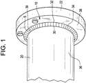
- FIG. 1 is an exemplary illustration of a welded joint 10.
- the welded joint 10 joins a pipe 20 and a flange 22 together, where the 20 and the flange 22 are part of a gas turbine assembly (not shown).
- FIG. 1 illustrates the welded joint 10 joining a nozzle and flange of a turbine together, the welded joint 10 could be employed in different applications as well.
- the welded joint 10 includes two weld toes 30 and 32.
- the weld toes 30, 32 represent the region of the weld joint 10 between a weld metal 34 of the welded joint 10 and a base metal.
- the weld toe 30 represents the region of the weld joint 10 between the weld metal 34 and a base metal 36 of the pipe 20.
- the weld toe 32 represents the region of the weld joint 20 between the weld metal 34 and a base metal 38 of the flange 22.
- the welded joint 10 has an outer surface S that includes a series of raised protrusions 39 that are created during welding of the pipe 20 with the flange 22.
- the pipe 20 and the flange 22 are welded together by arc welding, however it is understood that other types of welding processes may be used as well.
- the weld toes 30, 32 are created by welding the pipe 20 and the flange 22 together. After creating the welded toes 30, 32 by a welding process such as arc welding, the weld toes 30, 32 are then heated to a selected temperature, and subsequently quenched by a cooling medium. Heating and quenching the weld toes 30, 32 introduces compressive stress to the weld toes 30, 32.
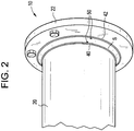
- FIG. 2 is an illustration of the welded joint 10 being heated by resistance wires 40, 42.
- the weld toe 30 (shown in FIG. 1 ) is covered by a length of electrical resistance wire 40 and the weld toe 32 (shown in FIG. 1 ) is covered by a length of electrical resistance wire 42.
- the electrical resistance wires 40 and 42 are heating element wires that are connected to a power supply through a current control device (not shown).
- the electrical resistance wires 40, 42 are any type of resistance wires typically used for high-power resistors and heating elements.
- the resistance wires 40, 42 may be constructed from a Nichrome ® or a Kanthal alloy, however it is understood that the resistance wires 40, 42 could be constructed from other types of alloys as well.
- thermocouple 50 may also be placed adjacent to one or both of the resistance wires 40, 42 for monitoring the temperature of the weld toes 30 and 32.
- the thermocouples 50 are in communication with a data acquisition device (not shown), where a user monitors the temperature of the welded toes 30 and 32 through the data acquisition device. Monitoring the temperature of the welded toes 30, 32 ensures that the temperature of the weld toes 30, 32 do not exceed a selected temperature.
- the selected temperature represents a specific temperature range at which tensile stress is introduced to the welded joint 10. Specifically, referring to both of FIGS. 1-2 , as the welded joint 10 is heated to the selected temperature, the weld toes 30, 32 thermally expand.
- the strain of the welded toes 30, 32 are restricted by the surrounding pipe 20 and flange 22. Therefore, as the weld toes 30, 32 expand, the elastic limit of the material of the welded joint 10 at the welded toes 30, 32 is exceeded.
- the weld toes 30, 32 are then maintained at the selected temperature for a selected amount of time.
- the welded joint 10 is then quenched or rapidly cooled by a cooling medium such as, for example, compressed air or atomized water. Compressed air is typically used for smaller welded joints, and atomized water is typically used for larger welded joints.
- the metal material located in the weld toes 30, 32 are shrunk which generates tensile strain. If the weld toe 30, 32 are cooled rapidly by quenching, the tensile strain located in the weld toes 30, 32 will be more than the compression strain induced during heating to the specified temperature. Accordingly, residual strain is generated in the weld toes 30, 32 as the weld toes 30, 32 are cooled to room temperature.
- the weld joint 10 is generally strain controlled, which results in the strain tending to be about zero at room temperature. Thus, residual compression stress will be generated in the weld toe 30, 32.
- the selected temperature should be high enough such that the elastic limit of the material of the welded joint 10 should be exceeded, leading to compression yield. Quenching the weld toes 30, 32 after heating allows the weld toes 30, 32 to normally cool without a cooling medium typically results in residual tensile stress instead of compression stress being introduced in the weld toes 30, 32, which in turn may actually reduce the fatigue life of the welded joint 10.
- the pipe 20 and the flange 22 are each constructed from a stainless steel alloy.
- the selected temperature ranges from about 400°F to about 500°F, which is the temperature needed to introduce compressive stress into the welded joint 10.
- the welded joint 10 is maintained at the selected temperature for the selected amount of time, which is about five to about ten minutes. Then, the welded joint 10 is quenched with a cooling medium to reach about room temperature. In one embodiment, the welded joint 10 is quenched.
- a stainless steel alloy is discussed, it is understood that the welded joint 10 may be constructed from other types of metal based materials as well. The selected temperature depends on the specific material that the welded joint 10 is constructed from, and may be adjusted accordingly to introduce compression stress being introduced in the welded joint 10.
- the outer surface S of the welded joint 10 has been grounded to substantially remove the series of raised protrusions 39 such that the weld toes 30, 32 (shown in FIG. 1 ) have a generally smooth contour. Grinding the outer surface S tends to result in lower stress concentrations in the welded joint 10.
- the outer surface S is ground by an angle grinder, however it is understood that other device may be used as well to grind the welded joint 10.
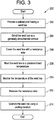
- FIG. 3 is a process flow diagram illustrating a method 200 of introducing compressive stress in a welded joint 10.
- the method 200 begins at step 202, where the welded joint 10 is provided.
- the welded joint 10 joins a pipe 20 and a flange 22 of a turbine assembly (not shown) together.
- the welded joint 10 includes two weld toes 30 and 32.
- the weld toe 30 represents the region of the weld joint 10 between the weld metal 34 and a base metal 36 of the pipe 20.
- the weld toe 32 represents the region of the weld joint 20 between the weld metal 34 and a base metal 38 of the flange 22.
- the welded joint 10 has an outer surface S that includes a series of raised protrusions 39 that are created during welding of the pipe 20 with the flange 22. Method 200 may then proceed to step 204.
- step 204 the outer surface S of the welded toes 30, 32 are ground to a generally smooth contour. Specifically, referring to FIG. 1 , the series of raised protrusions 39 are substantially removed, thereby leaving a generally smooth outer surface S. Method 200 may then proceed to step 206.
- step 206 the weld toes 30 and 32 are covered with resistance wire 40 and 42.
- the weld toe 30 is covered by a length of electrical resistance wire 40 and the weld toe 32 is covered by a length of electrical resistance wire 42.
- the electrical resistance wires 40 and 42 are heating element wires that are connected to a power supply through a current control device (not shown). Method 200 may then proceed to step 208.
- step 208 the weld toes 30 and 32 are heated to a selected temperature.
- the selected temperature represents a specific temperature range at which tensile stress is introduced to the welded joint 10.
- the pipe 20 and the flange 22 are each constructed from a stainless steel alloy, and the selected temperature ranges from about 400°F to about 500°F. Method 200 may then proceed to step 210.
- thermocouples 50 the temperature of the welded toes 30, 32 is monitored by thermocouples 50.
- one or more thermocouples 50 are placed adjacent to one or both of the resistance wires 40, 42 for monitoring the temperature of the weld toes 30 and 32.
- the thermocouples 50 are in communication with a data acquisition device (not shown), where a user monitors the temperature of the welded toes 30 and 32 through the data acquisition device. Monitoring the temperature of the welded toes 30, 32 ensures that the temperature of the weld toes 30, 32 does not exceed the selected temperature. Method 200 may then proceed to step 212.
- step 212 the resistance wires 40 and 42 are removed from the welded toes 30 and 32. Method 200 may then proceed to step 214.
- the weld toes 30 and 32 are quenched by a cooling medium.
- the cooling medium is generally any type of medium used to quench or rapidly cool a metal based material.
- the welded joint 10 is quenched with a cooling medium to reach about room temperature. Quenching the welded joint 10 results in the welded toes 30, 32 being compressed by the surrounding area of the welded joint 10. Compressing the weld toes 30, 32 results in compression stress being induced in the welded toes 30, 32. Compression stress results in increased fatigue life of the welded toes 30, 32. Method 200 may then terminate.
Landscapes
- Chemical & Material Sciences (AREA)
- Engineering & Computer Science (AREA)
- Physics & Mathematics (AREA)
- Thermal Sciences (AREA)
- Crystallography & Structural Chemistry (AREA)
- Mechanical Engineering (AREA)
- Materials Engineering (AREA)
- Metallurgy (AREA)
- Organic Chemistry (AREA)
- Heat Treatment Of Articles (AREA)
Abstract
A method of introducing compressive stress in a weld joint having at least one weld toe is provided. The method includes the step of covering the weld toe of the welded joint with a resistance wire. The method also includes the step of heating the weld toe by the resistance wire, where the weld toe is heated to a selected temperature. The method includes the step of maintaining the weld toe at the selected temperature for a selected amount of time. The method includes the step of removing the resistance wire from the weld toe. The method includes the step of quenching the weld toe with a cooling medium. Compressive stress is introduced to the weld toe during quenching.
Description
- The subject matter disclosed herein relates to a method of introducing compressive stress in a welded joint, and particularly to a method of introducing compressive stress in a weld toe of the welded joint.
- Fatigue is a common failure mode for welded joints. Cracks in the welded joint tend to emanate from the weld toe of the welded joint. The weld toe is the region on the surface of the weld joint at the transition point between the weld metal and the base metal. The weld toe has high stress concentrations as well as residual stress that both contribute to the high occurrence of fatigue. One example of fatigue occurs in a welded joint that joins the pipe with the fuel nozzle flange of a gas turbine. In one example, 304 stainless steel may be used for the pipe and fuel nozzle flange. High frequency vibration may be generated as the feeding mode of the fuel is changed during operation of the gas turbine, which may lead to recycling stress on the pipe and fuel nozzle.. Moreover, the weld joint is also subjected to vibration from operation of the gas turbine as well. Constant exposure to thermal shock and vibration may contribute to the occurrence of fatigue of the welded joint.
- Several approaches currently exist for increasing the fatigue strength and durability of a welded joint, however all these approaches each have drawbacks. For example, in one approach shot peening is performed on the welded joint to improve fatigue strength. However, shot peening can be difficult to perform on smaller welded joints or on certain areas of the turbine. In another approach, welding process parameters such as welding current, arc voltage, weld speed, or wire diameter or elongation could be adjusted to improve the weld. However, sometimes some of the welding process parameters cannot be adjusted for various reasons. In another approach, the entire assembly, such as the entire fuel nozzle and the fuel nozzle flange could be placed in an oven for annealing. However, annealing the entire fuel nozzle assembly can be costly. Accordingly, a need exists for a cost effective process that reduces the possibility of failure in a welded joint by fatigue.
- According to one aspect, the invention resides in a method of introducing compressive stress in a weld joint having at least one weld toe. The method includes the step of covering the weld toe of the welded joint with a resistance wire. The method also includes the step of heating the weld toe by the resistance wire, where the weld toe is heated to a selected temperature. The method includes the step of maintaining the weld toe at the selected temperature for a selected amount of time. The method includes the step of removing the resistance wire from the weld toe. The method includes the step of quenching the weld toe with a cooling medium. Compressive stress is introduced to the weld toe during quenching.
- These and other advantages and features will become more apparent from the following description taken in conjunction with the drawings.
- Embodiments of the present invention will be described, by way of example only, with reference to the accompanying drawings in which:
-
FIG. 1 is an exemplary illustration of a welded joint joining a fuel nozzle and a flange; -
FIG 2 is an illustration of the welded joint inFIG. 1 covered by resistance wire at a weld toe; and -
FIG 3 is a flow diagram illustrating a method of introducing compressive stress at the weld toe. - The detailed description explains embodiments of the invention, together with advantages and features, by way of example with reference to the drawings.
-
FIG. 1 is an exemplary illustration of awelded joint 10. In the exemplary embodiment as shown, thewelded joint 10 joins apipe 20 and aflange 22 together, where the 20 and theflange 22 are part of a gas turbine assembly (not shown). It should be noted that whileFIG. 1 illustrates thewelded joint 10 joining a nozzle and flange of a turbine together, thewelded joint 10 could be employed in different applications as well. Thewelded joint 10 includes twoweld toes weld toes weld joint 10 between aweld metal 34 of thewelded joint 10 and a base metal. Specifically, theweld toe 30 represents the region of theweld joint 10 between theweld metal 34 and abase metal 36 of thepipe 20. Theweld toe 32 represents the region of theweld joint 20 between theweld metal 34 and abase metal 38 of theflange 22. Thewelded joint 10 has an outer surface S that includes a series of raisedprotrusions 39 that are created during welding of thepipe 20 with theflange 22. In one embodiment, thepipe 20 and theflange 22 are welded together by arc welding, however it is understood that other types of welding processes may be used as well. - The
weld toes pipe 20 and theflange 22 together. After creating thewelded toes weld toes weld toes weld toes FIG. 2 is an illustration of thewelded joint 10 being heated byresistance wires FIG. 1 ) is covered by a length ofelectrical resistance wire 40 and the weld toe 32 (shown inFIG. 1 ) is covered by a length ofelectrical resistance wire 42. Theelectrical resistance wires electrical resistance wires resistance wires resistance wires - A
thermocouple 50 may also be placed adjacent to one or both of theresistance wires weld toes thermocouples 50 are in communication with a data acquisition device (not shown), where a user monitors the temperature of thewelded toes welded toes weld toes welded joint 10. Specifically, referring to both ofFIGS. 1-2 , as thewelded joint 10 is heated to the selected temperature, theweld toes base metal 36 of thepipe 20 and thebase metal 38 of theflange 22 compress thewelded toes welded toes welded toes pipe 20 andflange 22. Therefore, as theweld toes welded joint 10 at thewelded toes weld toes welded joint 10 is then quenched or rapidly cooled by a cooling medium such as, for example, compressed air or atomized water. Compressed air is typically used for smaller welded joints, and atomized water is typically used for larger welded joints. - As the
weld toes weld toes weld toe weld toes weld toes weld toes weld toe weld toes weld toes weld toes - In one exemplary embodiment, the
pipe 20 and theflange 22 are each constructed from a stainless steel alloy. In this embodiment, the selected temperature ranges from about 400°F to about 500°F, which is the temperature needed to introduce compressive stress into the welded joint 10. The welded joint 10 is maintained at the selected temperature for the selected amount of time, which is about five to about ten minutes. Then, the welded joint 10 is quenched with a cooling medium to reach about room temperature. In one embodiment, the welded joint 10 is quenched. Although a stainless steel alloy is discussed, it is understood that the welded joint 10 may be constructed from other types of metal based materials as well. The selected temperature depends on the specific material that the welded joint 10 is constructed from, and may be adjusted accordingly to introduce compression stress being introduced in the welded joint 10. - Referring now to
FIG. 2 , the outer surface S of the welded joint 10 has been grounded to substantially remove the series of raisedprotrusions 39 such that theweld toes 30, 32 (shown inFIG. 1 ) have a generally smooth contour. Grinding the outer surface S tends to result in lower stress concentrations in the welded joint 10. In one exemplary embodiment, the outer surface S is ground by an angle grinder, however it is understood that other device may be used as well to grind the welded joint 10. - A method of introducing compressive stress in the welded joint 10 will now be discussed.
FIG. 3 is a process flow diagram illustrating amethod 200 of introducing compressive stress in a welded joint 10. Themethod 200 begins atstep 202, where the welded joint 10 is provided. Referring back toFIG. 1 , the welded joint 10 joins apipe 20 and aflange 22 of a turbine assembly (not shown) together. The welded joint 10 includes twoweld toes weld toe 30 represents the region of the weld joint 10 between theweld metal 34 and abase metal 36 of thepipe 20. Theweld toe 32 represents the region of the weld joint 20 between theweld metal 34 and abase metal 38 of theflange 22. The welded joint 10 has an outer surface S that includes a series of raisedprotrusions 39 that are created during welding of thepipe 20 with theflange 22.Method 200 may then proceed to step 204. - In
step 204, the outer surface S of the weldedtoes FIG. 1 , the series of raisedprotrusions 39 are substantially removed, thereby leaving a generally smooth outersurface S. Method 200 may then proceed to step 206. - In
step 206, theweld toes resistance wire FIGS. 1-2 , theweld toe 30 is covered by a length ofelectrical resistance wire 40 and theweld toe 32 is covered by a length ofelectrical resistance wire 42. Theelectrical resistance wires Method 200 may then proceed to step 208. - In
step 208, theweld toes pipe 20 and theflange 22 are each constructed from a stainless steel alloy, and the selected temperature ranges from about 400°F to about 500°F. Method 200 may then proceed to step 210. - In
step 210, the temperature of the weldedtoes thermocouples 50. Referring back toFIG. 2 , one ormore thermocouples 50 are placed adjacent to one or both of theresistance wires weld toes thermocouples 50 are in communication with a data acquisition device (not shown), where a user monitors the temperature of the weldedtoes toes weld toes Method 200 may then proceed to step 212. - In
step 212, theresistance wires toes Method 200 may then proceed to step 214. - In
step 214, theweld toes toes weld toes toes toes Method 200 may then terminate. - While the invention has been described in detail in connection with only a limited number of embodiments, it should be readily understood that the invention is not limited to such disclosed embodiments. Rather, the invention can be modified to incorporate any number of variations, alterations, substitutions or equivalent arrangements not heretofore described, but which are commensurate with the spirit and scope of the invention. Additionally, while various embodiments of the invention have been described, it is to be understood that aspects of the invention may include only some of the described embodiments. Accordingly, the invention is not to be seen as limited by the foregoing description, but is only limited by the scope of the appended claims.
Claims (11)
- A method of introducing compressive stress in a welded (10) joint having at least one weld toe (30,32), comprising:covering the at least one weld toe (30,32) of the welded joint (10) with a resistance wire (40,42);heating the at least one weld toe (30,32) by the resistance wire (40,42), wherein the at least one weld toe (30,32) is heated to a selected temperature;maintaining the at least one weld toe (30,32) at the selected temperature for a selected amount of time;removing the resistance wire (40,42) from the at least one weld toe (30,32); andquenching the at least one weld toe (30,32) with a cooling medium, whereby compressive stress is introduced to the at least one weld toe (30,32) during quenching.
- The method of claim 1, comprising grinding an outer surface of the welded joint (10) to a generally smooth contour before covering the at least one weld toe (30,32) with resistance wire (40,42).
- The method of claim 1 or 2, comprising applying at least one of compressed air and atomized water as the cooling medium.
- The method of any of claims 1 to 3, comprising monitoring a temperature of the at least one weld toe (30,32) with a thermocouple (50), wherein the thermocouple is placed adjacent the at least one weld toe (30,32).
- The method of claim 4, comprising determining if the selected temperature of the at least one weld toe (30,32) has been exceeded.
- The method of any preceding claim, wherein the selected temperature ranges from about 400°F to about 500°F.
- The method of any preceding claim, wherein the selected amount of time is about five to about ten minutes.
- The method of any preceding claim, comprising cooling the welded toe (30,32) to about room temperature.
- The method of any preceding claim, wherein the welded joint (10) is constructed from a stainless steel alloy.
- The method of any preceding claim, wherein the welded joint joins a nozzle and a flange of a turbine engine.
- The method of claim 5, wherein the thermocouple detects if the selected temperature has been exceeded.
Applications Claiming Priority (1)
| Application Number | Priority Date | Filing Date | Title |
|---|---|---|---|
| US13/036,357 US20120217227A1 (en) | 2011-02-28 | 2011-02-28 | Method of introducing compressive stress in a welded joint |
Publications (1)
| Publication Number | Publication Date |
|---|---|
| EP2492362A1 true EP2492362A1 (en) | 2012-08-29 |
Family
ID=45774032
Family Applications (1)
| Application Number | Title | Priority Date | Filing Date |
|---|---|---|---|
| EP12157198A Withdrawn EP2492362A1 (en) | 2011-02-28 | 2012-02-27 | Method of introducing compressive stress in a welded joint |
Country Status (4)
| Country | Link |
|---|---|
| US (1) | US20120217227A1 (en) |
| EP (1) | EP2492362A1 (en) |
| JP (1) | JP2012179655A (en) |
| CN (1) | CN102672372A (en) |
Citations (7)
| Publication number | Priority date | Publication date | Assignee | Title |
|---|---|---|---|---|
| US4229235A (en) * | 1977-10-25 | 1980-10-21 | Hitachi, Ltd. | Heat-treating method for pipes |
| JPS57187192A (en) * | 1981-05-12 | 1982-11-17 | Toyo Eng Corp | Method for elimination of residual tensile stress after welding |
| JPS58123832A (en) * | 1982-01-18 | 1983-07-23 | Hitachi Ltd | Heat treatment for nozzle safe end part of vessel |
| JPS5943828A (en) * | 1982-09-07 | 1984-03-12 | Mitsubishi Heavy Ind Ltd | Method for relieving residual stress in piping |
| JPS60135526A (en) * | 1983-12-23 | 1985-07-18 | Ishikawajima Harima Heavy Ind Co Ltd | Heat treatment method for double pipe welds |
| US4948435A (en) * | 1988-01-04 | 1990-08-14 | Butler Thomas M | Method for inhibiting stress corrosion cracking |
| US20060113010A1 (en) * | 2004-12-01 | 2006-06-01 | Noboru Saitou | Heat treatment method and device for piping |
Family Cites Families (3)
| Publication number | Priority date | Publication date | Assignee | Title |
|---|---|---|---|---|
| US2350532A (en) * | 1941-06-04 | 1944-06-06 | Edward A Richardson | Method of welding |
| US5916468A (en) * | 1996-07-08 | 1999-06-29 | Hitachi Metals Ltd. | Electrically weldable pipe joint and production method thereof |
| US8058583B2 (en) * | 2003-07-16 | 2011-11-15 | Dan Danks | Apparatus and method for electroslag welding of rails |
-
2011
- 2011-02-28 US US13/036,357 patent/US20120217227A1/en not_active Abandoned
-
2012
- 2012-02-22 JP JP2012035707A patent/JP2012179655A/en active Pending
- 2012-02-27 EP EP12157198A patent/EP2492362A1/en not_active Withdrawn
- 2012-02-28 CN CN2012100590512A patent/CN102672372A/en active Pending
Patent Citations (7)
| Publication number | Priority date | Publication date | Assignee | Title |
|---|---|---|---|---|
| US4229235A (en) * | 1977-10-25 | 1980-10-21 | Hitachi, Ltd. | Heat-treating method for pipes |
| JPS57187192A (en) * | 1981-05-12 | 1982-11-17 | Toyo Eng Corp | Method for elimination of residual tensile stress after welding |
| JPS58123832A (en) * | 1982-01-18 | 1983-07-23 | Hitachi Ltd | Heat treatment for nozzle safe end part of vessel |
| JPS5943828A (en) * | 1982-09-07 | 1984-03-12 | Mitsubishi Heavy Ind Ltd | Method for relieving residual stress in piping |
| JPS60135526A (en) * | 1983-12-23 | 1985-07-18 | Ishikawajima Harima Heavy Ind Co Ltd | Heat treatment method for double pipe welds |
| US4948435A (en) * | 1988-01-04 | 1990-08-14 | Butler Thomas M | Method for inhibiting stress corrosion cracking |
| US20060113010A1 (en) * | 2004-12-01 | 2006-06-01 | Noboru Saitou | Heat treatment method and device for piping |
Also Published As
| Publication number | Publication date |
|---|---|
| JP2012179655A (en) | 2012-09-20 |
| US20120217227A1 (en) | 2012-08-30 |
| CN102672372A (en) | 2012-09-19 |
Similar Documents
| Publication | Publication Date | Title |
|---|---|---|
| US6536110B2 (en) | Integrally bladed rotor airfoil fabrication and repair techniques | |
| CN104924018B (en) | A kind of Large Rotor big cross section crackle field repairing method | |
| EP1927668B1 (en) | Restoration method for deteriorated part and restoration apparatus for deteriorated part | |
| US20100140230A1 (en) | Method for the manufacture of a welded rotor for a gas-turbine engine | |
| EP2492362A1 (en) | Method of introducing compressive stress in a welded joint | |
| CN101784682B (en) | Deteriorated portion reproducing method | |
| JP2013107101A (en) | Method for repairing metal component | |
| KR101906092B1 (en) | Method for heat treatment of stainless member, and method for producing forged stainless product | |
| Andrawes et al. | Effects of DC current on the stress-strain curve and hardness of 6061 T6511 aluminum | |
| EP2620250A1 (en) | Heat treatment method for branch pipe welded portion | |
| JP2012016750A (en) | Shaft-thickening method | |
| JP5298081B2 (en) | Pipe residual stress improvement method and construction management method | |
| CN116234934A (en) | Method of Repairing Components by Heat Treatment | |
| JP2022142811A (en) | Annealing apparatus and annealing method for weld zone | |
| JP6015681B2 (en) | Method for manufacturing boiler or water-cooled panel for converter OG equipment and method for extending the life of boiler or water-cooled panel for converter OG equipment | |
| CN113210799B (en) | Welding residual stress control method and device based on longitudinal cyclic load | |
| KR101568598B1 (en) | Repair apparatus for cooling pip of blast furnace and repair method for cooling pip of blast furnace | |
| JPH06288549A (en) | How to repair a gas turbine combustor | |
| JP2020029609A (en) | Treatment method for improving fretting fatigue strength | |
| JP2004202509A (en) | On-site welding repair method for hydraulic equipment | |
| JP2007167882A (en) | Enlarge-working method for shaft | |
| WO2004065051A1 (en) | Turbine refurbishment | |
| JP2011219815A (en) | Heat-treatment method for piping | |
| JP2011202649A (en) | Method for correcting deformation of gas turbine member | |
| JP2004277863A (en) | Induction heat treatment equipment |
Legal Events
| Date | Code | Title | Description |
|---|---|---|---|
| PUAI | Public reference made under article 153(3) epc to a published international application that has entered the european phase |
Free format text: ORIGINAL CODE: 0009012 |
|
| AK | Designated contracting states |
Kind code of ref document: A1 Designated state(s): AL AT BE BG CH CY CZ DE DK EE ES FI FR GB GR HR HU IE IS IT LI LT LU LV MC MK MT NL NO PL PT RO RS SE SI SK SM TR |
|
| AX | Request for extension of the european patent |
Extension state: BA ME |
|
| 17P | Request for examination filed |
Effective date: 20130228 |
|
| STAA | Information on the status of an ep patent application or granted ep patent |
Free format text: STATUS: THE APPLICATION IS DEEMED TO BE WITHDRAWN |
|
| 18D | Application deemed to be withdrawn |
Effective date: 20140901 |