EP2492222B1 - Glass sheet belt conveyor - Google Patents
Glass sheet belt conveyor Download PDFInfo
- Publication number
- EP2492222B1 EP2492222B1 EP20120156766 EP12156766A EP2492222B1 EP 2492222 B1 EP2492222 B1 EP 2492222B1 EP 20120156766 EP20120156766 EP 20120156766 EP 12156766 A EP12156766 A EP 12156766A EP 2492222 B1 EP2492222 B1 EP 2492222B1
- Authority
- EP
- European Patent Office
- Prior art keywords
- conveyor
- supporting surface
- main supporting
- belt
- glass sheet
- Prior art date
- Legal status (The legal status is an assumption and is not a legal conclusion. Google has not performed a legal analysis and makes no representation as to the accuracy of the status listed.)
- Not-in-force
Links
- 239000011521 glass Substances 0.000 title claims description 31
- 238000003754 machining Methods 0.000 claims description 9
- 230000000284 resting effect Effects 0.000 claims description 4
- 239000002184 metal Substances 0.000 claims description 3
- 239000012528 membrane Substances 0.000 description 4
- 229910000831 Steel Inorganic materials 0.000 description 2
- 239000000356 contaminant Substances 0.000 description 2
- 239000002826 coolant Substances 0.000 description 2
- 238000005553 drilling Methods 0.000 description 2
- 239000000428 dust Substances 0.000 description 2
- 239000010959 steel Substances 0.000 description 2
- 230000000712 assembly Effects 0.000 description 1
- 238000000429 assembly Methods 0.000 description 1
- 238000011109 contamination Methods 0.000 description 1
- 239000013536 elastomeric material Substances 0.000 description 1
- 238000012423 maintenance Methods 0.000 description 1
- 230000002093 peripheral effect Effects 0.000 description 1
- 230000001681 protective effect Effects 0.000 description 1
- 239000012779 reinforcing material Substances 0.000 description 1
- 125000006850 spacer group Chemical group 0.000 description 1
- 230000003313 weakening effect Effects 0.000 description 1
Images



Classifications
-
- B—PERFORMING OPERATIONS; TRANSPORTING
- B65—CONVEYING; PACKING; STORING; HANDLING THIN OR FILAMENTARY MATERIAL
- B65G—TRANSPORT OR STORAGE DEVICES, e.g. CONVEYORS FOR LOADING OR TIPPING, SHOP CONVEYOR SYSTEMS OR PNEUMATIC TUBE CONVEYORS
- B65G49/00—Conveying systems characterised by their application for specified purposes not otherwise provided for
- B65G49/05—Conveying systems characterised by their application for specified purposes not otherwise provided for for fragile or damageable materials or articles
- B65G49/06—Conveying systems characterised by their application for specified purposes not otherwise provided for for fragile or damageable materials or articles for fragile sheets, e.g. glass
- B65G49/061—Lifting, gripping, or carrying means, for one or more sheets forming independent means of transport, e.g. suction cups, transport frames
-
- B—PERFORMING OPERATIONS; TRANSPORTING
- B65—CONVEYING; PACKING; STORING; HANDLING THIN OR FILAMENTARY MATERIAL
- B65G—TRANSPORT OR STORAGE DEVICES, e.g. CONVEYORS FOR LOADING OR TIPPING, SHOP CONVEYOR SYSTEMS OR PNEUMATIC TUBE CONVEYORS
- B65G21/00—Supporting or protective framework or housings for endless load-carriers or traction elements of belt or chain conveyors
- B65G21/20—Means incorporated in, or attached to, framework or housings for guiding load-carriers, traction elements or loads supported on moving surfaces
- B65G21/2027—Suction retaining means
- B65G21/2036—Suction retaining means for retaining the load on the load-carrying surface
-
- B—PERFORMING OPERATIONS; TRANSPORTING
- B65—CONVEYING; PACKING; STORING; HANDLING THIN OR FILAMENTARY MATERIAL
- B65G—TRANSPORT OR STORAGE DEVICES, e.g. CONVEYORS FOR LOADING OR TIPPING, SHOP CONVEYOR SYSTEMS OR PNEUMATIC TUBE CONVEYORS
- B65G49/00—Conveying systems characterised by their application for specified purposes not otherwise provided for
- B65G49/05—Conveying systems characterised by their application for specified purposes not otherwise provided for for fragile or damageable materials or articles
- B65G49/06—Conveying systems characterised by their application for specified purposes not otherwise provided for for fragile or damageable materials or articles for fragile sheets, e.g. glass
- B65G49/063—Transporting devices for sheet glass
- B65G49/064—Transporting devices for sheet glass in a horizontal position
-
- B—PERFORMING OPERATIONS; TRANSPORTING
- B65—CONVEYING; PACKING; STORING; HANDLING THIN OR FILAMENTARY MATERIAL
- B65G—TRANSPORT OR STORAGE DEVICES, e.g. CONVEYORS FOR LOADING OR TIPPING, SHOP CONVEYOR SYSTEMS OR PNEUMATIC TUBE CONVEYORS
- B65G2249/00—Aspects relating to conveying systems for the manufacture of fragile sheets
- B65G2249/04—Arrangements of vacuum systems or suction cups
- B65G2249/045—Details of suction cups suction cups
Definitions
- the present invention relates to a glass sheet belt conveyor.
- the present invention is particularly, though not exclusively, advantageous for use on glass sheet grinding and/or drilling machines, to which the following description refers purely by way of example.
- a grinding/drilling machine comprises one or more machining heads; and a feed assembly for feeding the work sheet along a grinding path, or holding the sheet in a given reference position.
- Known feed assemblies normally comprise one or more pairs of belt conveyors; each conveyor comprises a draw belt, which defines a supporting surface for the work sheet and has a row of recesses, each formed through the draw belt and having an opening that comes out on the supporting surface and is closed in use by the glass sheet; and each recess is bounded by a bottom wall, in which are formed one or more passages connecting the recess to a suction source.
- JP 62175309 discloses a conveyor in which a powdered draw belt has a number of cavities closed by common closed outer ring belt.
- a similar solution is also disclosed in DE 1929 183 A1 , in which spacer are interposed between the draw belt ant the outer belt.
- a belt conveyor for conveying glass sheets as claimed in Claim 1.
- Number 1 in Figure 1 indicates as a whole a machine, e.g. a grinder, for machining a glass sheet 2.
- Machine 1 comprises a machining station 3 for machining glass sheet 2; and a conveyor 4 for feeding glass sheet 2 through machining station 3.
- conveyor 4 comprises two belt conveyors 6, each comprising a hollow supporting frame 7, at least two pulleys 8 (only one shown in Figure 1 ), and a powered draw belt 10 looped about pulleys 8 and reinforced with a number of side by side steel strands 11 spaced widthwise of draw belt 10.
- the strands are at least partly replaced with steel mesh or other equivalent metal reinforcing material.
- Belt 10 is bounded externally by a main supporting surface 13 facing glass sheet 2 in use, and has a delivery branch 10a, which is maintained contacting a top surface 15a of a fixed reference body 15 of frame 7 by a number of magnetic bodies 16 connected integrally to fixed body 15.
- Each draw belt 10 supports a suction retaining device 18 for securing glass sheet 2 to draw belt 10.
- device 18 comprises an annular body 20 surrounding draw belt 10 to completely cover main supporting surface 13 of draw belt 10, and integral with, e.g. glued or pressure cast to, draw belt 10.
- annular body 20 comprises two lateral portions or sides 21 resting on lateral portions of main supporting surface 13; and a rubber-coated annular portion 22, which surrounds sides 21, at a distance from main supporting surface 13, and defines a supporting surface 23 for supporting glass sheet 2 and parallel to and spaced apart from main supporting surface 13.
- rubber-coated portion 22 is separate from sides 21, and is connected in fluidtight manner to sides 21 in known manner.
- rubber-coated portion 22 and sides 21 form part of a one-piece body.
- sides 21 are connected in fluidtight manner to main supporting surface 13 to define an airtight chamber 25 together with belt 10 and rubber-coated portion 22.
- rubber-coated portion 22 comprises a number of elastically deformable membrane portions 26, each of which is located at a respective hole 27 formed through belt 10 to connect chamber 25 to a vacuum tank 28 connected to a known suction source not shown.
- Each membrane portion 26 comprises one or more through holes 26a connecting variable-volume chamber 25 to the outside. Holes 26a are much smaller in diameter than holes 27, have cross sections only allowing passage of a pressure signal, and are formed eccentrically with respect to holes 27, conveniently next to an outer peripheral edge of respective membrane portions 26, as shown in Figures 3 and 5 . In a variation not shown, portions 26 have no holes 26a.
- Each membrane portion 26 is designed so that it is positioned coplanar with the rest of belt 10, and therefore contacting glass sheet 2, in the absence of a vacuum in chamber 25 ( Figures 2 and 3a ), or rests partly on main supporting surface 13 to close relative hole 27, in the absence of glass sheet 2 ( Figure 3b ), or is set to an intermediate position retaining glass sheet 2 ( Figure 3c ).
- annular body 20 is replaced with a number of hollow bodies 30 aligned along draw belt 10 and spaced apart in the travelling direction of draw belt 10.
- Each hollow body 30 is conveniently parallelepiped-shaped or in the form of a hollow plate, has a concavity facing main supporting surface 13, is formed in one piece from elastomeric material, and comprises a bottom wall 31 defining one of elastically deformable portions 26; and a lateral wall 32, which surrounds a respective hole 27 and is positioned resting on and fitted in fluidtight manner to main supporting surface 13 to define a relative variable-volume chamber 33.
- each body 30 comprises an annular body defining lateral wall 32; and an elastically deformable bottom plate separate from the annular body and fitted to it in known fluidtight manner, e.g. glued or using other equivalent connecting means.
- Belt conveyor 6 described is therefore unaffected by external contaminants, i.e. dust, glass chips and/or coolant, due to suction holes 27, unlike known solutions, being isolated from the outside at all times. That is, holes 27 communicate at all times with a chamber which, when a glass sheet is present, is closed by the glass sheet, and, when there is no glass sheet, is cut off from the suction source by relative portion 26.
- the sheet retaining capacity of conveyors 6 therefore remains practically unchanged, with no need for any particular routine maintenance.
- the surface supporting the glass sheet is flat, so any foreign bodies and/or contaminants can be cleaned off easily.
- chambers 25 and 33 are in vacuum mode, and there are either no glass sheets on the conveyor or they only partly overlap one or more deformable portions 26, deformable portions 26 are always positioned closing respective holes 27, regardless of the position of deformable portions 26 along the path of glass sheets 2, thus greatly reducing air consumption.
- the conveyors described are also unaffected by the load and/or sudden changes in the load being conveyed, in that this is absorbed by draw belt 10, which is homogeneous and reinforced with substantially no change in its pull-resisting section.
- holes 26a improve the sheet retaining force of the conveyor.
- bodies 20 and 30 covering the sheet 2 supporting surface may be designed differently, and fitted differently to draw belt 10, from those described by way of example, while still serving to connect integrally to draw belt 10 a sheet supporting surface other than the main supporting surface of draw belt 10.
Landscapes
- Engineering & Computer Science (AREA)
- Mechanical Engineering (AREA)
- Container, Conveyance, Adherence, Positioning, Of Wafer (AREA)
- Belt Conveyors (AREA)
- Delivering By Means Of Belts And Rollers (AREA)
- Constituent Portions Of Griding Lathes, Driving, Sensing And Control (AREA)
Description
- The present invention relates to a glass sheet belt conveyor.
- The present invention is particularly, though not exclusively, advantageous for use on glass sheet grinding and/or drilling machines, to which the following description refers purely by way of example.
- As is known, a grinding/drilling machine comprises one or more machining heads; and a feed assembly for feeding the work sheet along a grinding path, or holding the sheet in a given reference position.
- Known feed assemblies normally comprise one or more pairs of belt conveyors; each conveyor comprises a draw belt, which defines a supporting surface for the work sheet and has a row of recesses, each formed through the draw belt and having an opening that comes out on the supporting surface and is closed in use by the glass sheet; and each recess is bounded by a bottom wall, in which are formed one or more passages connecting the recess to a suction source.
- In actual use, depending on the size of the sheets and/or the distance between consecutive sheets on the conveyor, at least one and normally more than one of the recesses often remain partly or even fully open. And, given the degree of contamination of the workplace by dust and/or glass grinding chips and/or coolant, it is only a matter of time before the recesses become clogged, thus gradually impairing the ability of the conveyor to retain the sheet. For this reason, know conveyors must be thoroughly cleaned every so often, which involves both direct labour and indirect downtime expense.
- Moreover, despite the suction in each recess or group of recesses being controlled according to the location of the recesses, the fact that some of them are often fully open greatly increases suction air consumption, at considerable cost over time, and at any rate makes it necessary to employ high-performance suction systems.
- Lastly, the presence, and especially the size of the openings in the recesses, result in local weakening of the draw belt.
JP 62175309
A similar solution is also disclosed inDE 1929 183 A1 , in which spacer are interposed between the draw belt ant the outer belt. - It is an object of the present invention to provide a glass sheet belt conveyor designed to provide a simple, low-cost solution to the above drawbacks.
- According to the present invention, there is provided a belt conveyor for conveying glass sheets, as claimed in Claim 1.
- A non-limiting embodiment of the present invention will be described by way of example with reference to the accompanying drawings, in which :
-
Figure 1 shows a schematic, substantially in blocks, of a glass sheet working machine featuring two belt conveyors in accordance with the teachings of the present invention; -
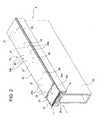
Figure 2 shows a larger-scale view in perspective of a detail inFigure 1 not constituting part of the invention; -
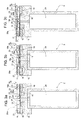
Figure 3 shows a larger-scale, front view of theFigure 2 detail in three different operating conditions; -
Figure 4 shows a larger-scale view in perspective of a further detail inFigure 1 according to the present invention; -
Figure 5 shows a larger-scale, front view, as inFigure 3 , of theFigure 4 detail in three different operating conditions. - Number 1 in
Figure 1 indicates as a whole a machine, e.g. a grinder, for machining a glass sheet 2. - Machine 1 comprises a
machining station 3 for machining glass sheet 2; and a conveyor 4 for feeding glass sheet 2 throughmachining station 3. - In the example shown, conveyor 4 comprises two
belt conveyors 6, each comprising a hollow supportingframe 7, at least two pulleys 8 (only one shown inFigure 1 ), and a powereddraw belt 10 looped aboutpulleys 8 and reinforced with a number of side byside steel strands 11 spaced widthwise ofdraw belt 10. In an alternative variation not shown, the strands are at least partly replaced with steel mesh or other equivalent metal reinforcing material. -
Belt 10 is bounded externally by a main supportingsurface 13 facing glass sheet 2 in use, and has adelivery branch 10a, which is maintained contacting atop surface 15a of a fixedreference body 15 offrame 7 by a number ofmagnetic bodies 16 connected integrally to fixedbody 15. - Each
draw belt 10 supports asuction retaining device 18 for securing glass sheet 2 to drawbelt 10. - As shown in
Figures 2 and3 ,device 18 comprises anannular body 20 surroundingdraw belt 10 to completely cover main supportingsurface 13 ofdraw belt 10, and integral with, e.g. glued or pressure cast to, drawbelt 10. - In the example shown,
annular body 20 comprises two lateral portions orsides 21 resting on lateral portions of main supportingsurface 13; and a rubber-coatedannular portion 22, which surroundssides 21, at a distance from main supportingsurface 13, and defines a supportingsurface 23 for supporting glass sheet 2 and parallel to and spaced apart from main supportingsurface 13. - In a first embodiment, rubber-coated
portion 22 is separate fromsides 21, and is connected in fluidtight manner tosides 21 in known manner. Alternatively, rubber-coatedportion 22 andsides 21 form part of a one-piece body. In both cases,sides 21 are connected in fluidtight manner to main supportingsurface 13 to define anairtight chamber 25 together withbelt 10 and rubber-coatedportion 22. - In both cases, rubber-coated
portion 22 comprises a number of elasticallydeformable membrane portions 26, each of which is located at arespective hole 27 formed throughbelt 10 to connectchamber 25 to avacuum tank 28 connected to a known suction source not shown. Eachmembrane portion 26 comprises one or more throughholes 26a connecting variable-volume chamber 25 to the outside.Holes 26a are much smaller in diameter thanholes 27, have cross sections only allowing passage of a pressure signal, and are formed eccentrically with respect toholes 27, conveniently next to an outer peripheral edge ofrespective membrane portions 26, as shown inFigures 3 and5 . In a variation not shown,portions 26 have noholes 26a. - Each
membrane portion 26 is designed so that it is positioned coplanar with the rest ofbelt 10, and therefore contacting glass sheet 2, in the absence of a vacuum in chamber 25 (Figures 2 and3a ), or rests partly on main supportingsurface 13 to closerelative hole 27, in the absence of glass sheet 2 (Figure 3b ), or is set to an intermediate position retaining glass sheet 2 (Figure 3c ). - In the
Figure 4 and5 variation,annular body 20 is replaced with a number ofhollow bodies 30 aligned alongdraw belt 10 and spaced apart in the travelling direction ofdraw belt 10. Eachhollow body 30 is conveniently parallelepiped-shaped or in the form of a hollow plate, has a concavity facing main supportingsurface 13, is formed in one piece from elastomeric material, and comprises abottom wall 31 defining one of elasticallydeformable portions 26; and alateral wall 32, which surrounds arespective hole 27 and is positioned resting on and fitted in fluidtight manner to main supportingsurface 13 to define a relative variable-volume chamber 33. - In another variation, not shown, each
body 30 comprises an annular body defininglateral wall 32; and an elastically deformable bottom plate separate from the annular body and fitted to it in known fluidtight manner, e.g. glued or using other equivalent connecting means. -
Belt conveyor 6 described is therefore unaffected by external contaminants, i.e. dust, glass chips and/or coolant, due tosuction holes 27, unlike known solutions, being isolated from the outside at all times. That is,holes 27 communicate at all times with a chamber which, when a glass sheet is present, is closed by the glass sheet, and, when there is no glass sheet, is cut off from the suction source byrelative portion 26. The sheet retaining capacity ofconveyors 6 therefore remains practically unchanged, with no need for any particular routine maintenance. Moreover, when idle, i.e. with no vacuum in the chambers, the surface supporting the glass sheet is flat, so any foreign bodies and/or contaminants can be cleaned off easily. - Moreover, when
chambers deformable portions 26,deformable portions 26 are always positioned closingrespective holes 27, regardless of the position ofdeformable portions 26 along the path of glass sheets 2, thus greatly reducing air consumption. - Unlike known solutions, the conveyors described are also unaffected by the load and/or sudden changes in the load being conveyed, in that this is absorbed by
draw belt 10, which is homogeneous and reinforced with substantially no change in its pull-resisting section. - Finally,
holes 26a improve the sheet retaining force of the conveyor. - Clearly, changes may be made to conveyor 6 without, however, departing from the protective scope of Claim 1. More specifically,
bodies belt 10, from those described by way of example, while still serving to connect integrally to drawbelt 10 a sheet supporting surface other than the main supporting surface ofdraw belt 10.
Claims (8)
- A belt conveyor for conveying glass sheets; the conveyor comprising a powered draw belt having a main supporting surface, and suction retaining means for securing a glass sheet to said draw belt; the conveyor being characterized in that said retaining means comprises a number of hollow bodies aligned along a said draw belt and spaced apart in the traveling direction od the draw belt; said hollow bodies resting on and at least partly covering said main supporting surface; each said hollow body defining a supporting surface for supporting said glass sheet, and which is spaced apart from said main supporting surface, and comprises at least one elastically deformable portion facing and spaced apart from said main supporting surface, and defining, with said main supporting surface, a respective variable-volume chamber connectable to a suction source.
- A conveyor as claimed in any one of the foregoing Claims, characterized in that said hollow body has a concavity facing said main supporting surface; each hollow body comprising a bottom wall defining one of said elastically deformable portion and a lateral wall surrounding a respective hole in the main supporting surface of said draw belt for communicating to the suction source and positioned resting on and fitted in a fliudtight manner to said main supporting surface.
- A conveyor as claimed in claim 1, characterized in that each of said hollow body comprises an annular body defining a lateral wall of said hollow body and an elastically deformable bottom plate separate from the annular body and fitted to the annular body in a fluidtight manner; said lateral wall surrounding a respective hole in the main supporting surface of said draw belt for communicating to the suction source.
- A conveyor as claimed in Claim 2 or 3, characterized in that said elastically deformable portion is movable between two limit positions, one of which closing said hole, and through an intermediate position retaining said glass sheet.
- A conveyor as claimed in Claim 4, characterized in that said lateral wall rests directly on said main supporting surface.
- A conveyor as claimed in any of the preceding Claims, characterized by comprising a reference body bounded by a supporting surface of said draw belt; said draw belt being fitted with metal members; and magnetic means, for retaining said metal members, being provided to keep said draw belt in contact with said reference body.
- A conveyor as claimed in Claim 2 or 3, characterized by comprising at least one further hole formed through each said elastically deformable portion to connect said variable-volume chamber to the outside; said hole being eccentric with respect to said hole connecting said variable-volume chamber to said suction source.
- A machine for machining glass sheets, the machine comprising at least one machining station for machining a glass sheet; and conveyor means for at least feeding said glass sheet through said machining station; the machine being characterized in that said conveyor means comprise at least one belt conveyor as claimed in Claim 1.
Applications Claiming Priority (1)
| Application Number | Priority Date | Filing Date | Title |
|---|---|---|---|
| ITTO2011A000152A IT1404269B1 (en) | 2011-02-23 | 2011-02-23 | BELT CONVEYOR FOR ADVANCING A GLASS SHEET. |
Publications (2)
| Publication Number | Publication Date |
|---|---|
| EP2492222A1 EP2492222A1 (en) | 2012-08-29 |
| EP2492222B1 true EP2492222B1 (en) | 2013-10-02 |
Family
ID=43976481
Family Applications (1)
| Application Number | Title | Priority Date | Filing Date |
|---|---|---|---|
| EP20120156766 Not-in-force EP2492222B1 (en) | 2011-02-23 | 2012-02-23 | Glass sheet belt conveyor |
Country Status (5)
| Country | Link |
|---|---|
| US (1) | US8931625B2 (en) |
| EP (1) | EP2492222B1 (en) |
| CN (1) | CN102673940A (en) |
| BR (1) | BR102012003929A2 (en) |
| IT (1) | IT1404269B1 (en) |
Families Citing this family (8)
| Publication number | Priority date | Publication date | Assignee | Title |
|---|---|---|---|---|
| KR101651253B1 (en) * | 2014-05-29 | 2016-08-26 | 주식회사 탑 엔지니어링 | Transferring belt for scribe apparatus and scribe apparatus having the same |
| FR3049941B1 (en) * | 2016-04-06 | 2018-04-13 | Saint- Gobain Glass France | CONVEYING AND HOLDING DEVICE FOR GLASS SHEET IN PARTICULAR IN A WASHING PLANT |
| EP3254992B1 (en) * | 2016-06-10 | 2023-08-02 | Heinrich Georg GmbH Maschinenfabrik | Transport device for suspended transport of goods using vacuum means |
| CN106276195B (en) * | 2016-08-16 | 2018-10-02 | 湖南国盛石墨科技有限公司 | A kind of Graphene glass conveyer belt rotating device |
| KR20180026299A (en) * | 2016-09-02 | 2018-03-12 | 코닝 인코포레이티드 | Glass processing apparatus and methods |
| CN111731851B (en) * | 2020-06-12 | 2025-05-27 | 江苏雷益自动化系统有限公司 | A glass conveyor belt anti-collision structure and device |
| EP4588861A1 (en) | 2024-01-18 | 2025-07-23 | SOMIC Verpackungsmaschinen GmbH & Co. KG | Conveyor device, conveyor belt for such a conveyor device, insertion unit for such a conveyor belt and use of such a conveyor belt |
| EP4610199B1 (en) | 2024-02-27 | 2026-03-04 | SOMIC Verpackungsmaschinen GmbH & Co. KG | Conveying device |
Family Cites Families (14)
| Publication number | Priority date | Publication date | Assignee | Title |
|---|---|---|---|---|
| US3477558A (en) * | 1966-10-27 | 1969-11-11 | Fred J Fleischauer | Air lift and vacuum conveyors and foraminous belt means therefor |
| DE1929183B2 (en) * | 1969-06-09 | 1972-04-06 | HWM Hermann Weh Maschinenfabrik KG, 4000 Dusseldorf | SUCTION CONVEYOR BELT FOR HOLDING AND CONVEYING PLATE-SHAPED OR OTHER CONVEYOR GOODS |
| GB2128953B (en) * | 1982-10-28 | 1986-04-09 | Bishopbarn Ltd | Conveyor with suction means for holding articles in contact therewith |
| JPS62175309A (en) * | 1986-01-28 | 1987-08-01 | Kakoki Gijutsu Service Kk | Suction force and rotary motion stabilizing device for suction belt of conveyor device |
| CA2308045C (en) * | 2000-05-31 | 2001-08-28 | Roy William Emery | Level lift and drop-off arrangement for a vacuum transfer mechanism |
| DE10056097A1 (en) * | 2000-11-13 | 2002-05-23 | Sundwig Kohler Gmbh | Conveyor belt for a suction belt conveyor |
| IT1320870B1 (en) * | 2000-12-19 | 2003-12-10 | Bottero Spa | BELT CONVEYOR FOR THE ADVANCE OF GLASS SLABS IN A GRINDING MACHINE AND GRINDING MACHINE INCLUDING SUCH |
| DE10104510B4 (en) * | 2001-01-31 | 2005-06-23 | Neuhäuser GmbH | Device for transporting workpieces |
| TWI327128B (en) * | 2003-07-08 | 2010-07-11 | Daifuku Kk | Plate-shaped work piece transporting apparatus |
| ITTO20030927A1 (en) * | 2003-11-21 | 2004-02-20 | Forvet S R L | VACUUM BELT CONVEYOR FOR SLABS. |
| CN2846334Y (en) * | 2005-09-19 | 2006-12-13 | 彩虹集团电子股份有限公司 | Glass base plate transport device |
| KR100721550B1 (en) * | 2006-01-19 | 2007-05-23 | 주식회사 태성기연 | Plate glass feeder |
| EP2386277B1 (en) * | 2010-04-20 | 2013-11-13 | The Procter and Gamble Company | Apparatus and method for receiving and transferring solid material |
| CN201951949U (en) * | 2011-01-14 | 2011-08-31 | 楚天科技股份有限公司 | Vacuum absorption type conveyor belt component |
-
2011
- 2011-02-23 IT ITTO2011A000152A patent/IT1404269B1/en active
-
2012
- 2012-02-22 CN CN2012100406336A patent/CN102673940A/en active Pending
- 2012-02-23 EP EP20120156766 patent/EP2492222B1/en not_active Not-in-force
- 2012-02-23 US US13/403,438 patent/US8931625B2/en active Active
- 2012-02-23 BR BR102012003929A patent/BR102012003929A2/en not_active Application Discontinuation
Also Published As
| Publication number | Publication date |
|---|---|
| US8931625B2 (en) | 2015-01-13 |
| BR102012003929A2 (en) | 2014-01-28 |
| EP2492222A1 (en) | 2012-08-29 |
| CN102673940A (en) | 2012-09-19 |
| ITTO20110152A1 (en) | 2012-08-24 |
| US20120211332A1 (en) | 2012-08-23 |
| IT1404269B1 (en) | 2013-11-15 |
Similar Documents
| Publication | Publication Date | Title |
|---|---|---|
| US8931625B2 (en) | Glass sheet belt conveyor | |
| JP2009184827A (en) | Conveyor device | |
| MX2019005734A (en) | Conveying device for conveying goods. | |
| US5947259A (en) | Conveyer for the transfer of workpieces, in particular workpiece carriers | |
| KR102679346B1 (en) | Board Turnover Machine Assembly and Board Turnover Machine | |
| EP1980505B1 (en) | Apparatus for placing battery plates in a line | |
| US20140169915A1 (en) | Deep-drawing packaging machine with electromotive lifting gear | |
| ITPC20130026A1 (en) | DEVICE FOR LOCKING AND HANDLING OF A PIECE IN A MACHINE TOOL AND MACHINE TOOL PROVIDED WITH THIS DEVICE | |
| KR102021195B1 (en) | Cleaning device for belt conveyor | |
| CN100506673C (en) | Sheet brakes with corresponding delivery and printing presses | |
| KR20140103232A (en) | Conveyor apparatus and method for blanking process | |
| US20080190741A1 (en) | Directional Change Twin-Belt Conveyor | |
| US20020121427A1 (en) | Belt conveyor for feeding sheets of glass on a grinding machine, and grinding machine comprising such a conveyor | |
| ES2568906T3 (en) | Workpiece transport system | |
| CN204896656U (en) | Belt feeder stores up area portion and prevents off tracking troughing idler | |
| JP5742196B2 (en) | Thin plate conveyor conveyor | |
| JP2006290555A (en) | Vacuum conveyor and belt for vacuum conveyor | |
| KR101504457B1 (en) | Grinding Device | |
| CN212371925U (en) | High-precision workpiece conveying mechanism of grinding machine | |
| CN107497816A (en) | Dust excluder | |
| KR101606977B1 (en) | Preventing device of abrasion for chute | |
| KR100580379B1 (en) | Plate glass feeder | |
| GB2390072A (en) | Vacuum belt, encircles vacuum belt guide | |
| CN119974483B (en) | Bottle embryo removing device and bottle embryo detection screening system | |
| US10059532B2 (en) | Conveyor |
Legal Events
| Date | Code | Title | Description |
|---|---|---|---|
| PUAI | Public reference made under article 153(3) epc to a published international application that has entered the european phase |
Free format text: ORIGINAL CODE: 0009012 |
|
| AK | Designated contracting states |
Kind code of ref document: A1 Designated state(s): AL AT BE BG CH CY CZ DE DK EE ES FI FR GB GR HR HU IE IS IT LI LT LU LV MC MK MT NL NO PL PT RO RS SE SI SK SM TR |
|
| AX | Request for extension of the european patent |
Extension state: BA ME |
|
| 17P | Request for examination filed |
Effective date: 20130227 |
|
| GRAP | Despatch of communication of intention to grant a patent |
Free format text: ORIGINAL CODE: EPIDOSNIGR1 |
|
| INTG | Intention to grant announced |
Effective date: 20130419 |
|
| GRAS | Grant fee paid |
Free format text: ORIGINAL CODE: EPIDOSNIGR3 |
|
| GRAA | (expected) grant |
Free format text: ORIGINAL CODE: 0009210 |
|
| AK | Designated contracting states |
Kind code of ref document: B1 Designated state(s): AL AT BE BG CH CY CZ DE DK EE ES FI FR GB GR HR HU IE IS IT LI LT LU LV MC MK MT NL NO PL PT RO RS SE SI SK SM TR |
|
| REG | Reference to a national code |
Ref country code: GB Ref legal event code: FG4D |
|
| REG | Reference to a national code |
Ref country code: AT Ref legal event code: REF Ref document number: 634489 Country of ref document: AT Kind code of ref document: T Effective date: 20131015 Ref country code: CH Ref legal event code: EP |
|
| REG | Reference to a national code |
Ref country code: IE Ref legal event code: FG4D |
|
| REG | Reference to a national code |
Ref country code: DE Ref legal event code: R096 Ref document number: 602012000348 Country of ref document: DE Effective date: 20131205 |
|
| REG | Reference to a national code |
Ref country code: CH Ref legal event code: NV Representative=s name: CABINET ROLAND NITHARDT CONSEILS EN PROPRIETE , CH |
|
| REG | Reference to a national code |
Ref country code: NL Ref legal event code: VDEP Effective date: 20131002 |
|
| PG25 | Lapsed in a contracting state [announced via postgrant information from national office to epo] |
Ref country code: SI Free format text: LAPSE BECAUSE OF FAILURE TO SUBMIT A TRANSLATION OF THE DESCRIPTION OR TO PAY THE FEE WITHIN THE PRESCRIBED TIME-LIMIT Effective date: 20131002 |
|
| REG | Reference to a national code |
Ref country code: LT Ref legal event code: MG4D |
|
| PG25 | Lapsed in a contracting state [announced via postgrant information from national office to epo] |
Ref country code: HR Free format text: LAPSE BECAUSE OF FAILURE TO SUBMIT A TRANSLATION OF THE DESCRIPTION OR TO PAY THE FEE WITHIN THE PRESCRIBED TIME-LIMIT Effective date: 20131002 Ref country code: NL Free format text: LAPSE BECAUSE OF FAILURE TO SUBMIT A TRANSLATION OF THE DESCRIPTION OR TO PAY THE FEE WITHIN THE PRESCRIBED TIME-LIMIT Effective date: 20131002 Ref country code: IS Free format text: LAPSE BECAUSE OF FAILURE TO SUBMIT A TRANSLATION OF THE DESCRIPTION OR TO PAY THE FEE WITHIN THE PRESCRIBED TIME-LIMIT Effective date: 20140202 Ref country code: FI Free format text: LAPSE BECAUSE OF FAILURE TO SUBMIT A TRANSLATION OF THE DESCRIPTION OR TO PAY THE FEE WITHIN THE PRESCRIBED TIME-LIMIT Effective date: 20131002 Ref country code: SE Free format text: LAPSE BECAUSE OF FAILURE TO SUBMIT A TRANSLATION OF THE DESCRIPTION OR TO PAY THE FEE WITHIN THE PRESCRIBED TIME-LIMIT Effective date: 20131002 Ref country code: LT Free format text: LAPSE BECAUSE OF FAILURE TO SUBMIT A TRANSLATION OF THE DESCRIPTION OR TO PAY THE FEE WITHIN THE PRESCRIBED TIME-LIMIT Effective date: 20131002 Ref country code: NO Free format text: LAPSE BECAUSE OF FAILURE TO SUBMIT A TRANSLATION OF THE DESCRIPTION OR TO PAY THE FEE WITHIN THE PRESCRIBED TIME-LIMIT Effective date: 20140102 Ref country code: BE Free format text: LAPSE BECAUSE OF FAILURE TO SUBMIT A TRANSLATION OF THE DESCRIPTION OR TO PAY THE FEE WITHIN THE PRESCRIBED TIME-LIMIT Effective date: 20131002 Ref country code: CZ Free format text: LAPSE BECAUSE OF FAILURE TO SUBMIT A TRANSLATION OF THE DESCRIPTION OR TO PAY THE FEE WITHIN THE PRESCRIBED TIME-LIMIT Effective date: 20131002 |
|
| PG25 | Lapsed in a contracting state [announced via postgrant information from national office to epo] |
Ref country code: ES Free format text: LAPSE BECAUSE OF FAILURE TO SUBMIT A TRANSLATION OF THE DESCRIPTION OR TO PAY THE FEE WITHIN THE PRESCRIBED TIME-LIMIT Effective date: 20131002 Ref country code: CY Free format text: LAPSE BECAUSE OF FAILURE TO SUBMIT A TRANSLATION OF THE DESCRIPTION OR TO PAY THE FEE WITHIN THE PRESCRIBED TIME-LIMIT Effective date: 20131002 Ref country code: LV Free format text: LAPSE BECAUSE OF FAILURE TO SUBMIT A TRANSLATION OF THE DESCRIPTION OR TO PAY THE FEE WITHIN THE PRESCRIBED TIME-LIMIT Effective date: 20131002 Ref country code: PL Free format text: LAPSE BECAUSE OF FAILURE TO SUBMIT A TRANSLATION OF THE DESCRIPTION OR TO PAY THE FEE WITHIN THE PRESCRIBED TIME-LIMIT Effective date: 20131002 Ref country code: RS Free format text: LAPSE BECAUSE OF FAILURE TO SUBMIT A TRANSLATION OF THE DESCRIPTION OR TO PAY THE FEE WITHIN THE PRESCRIBED TIME-LIMIT Effective date: 20131002 |
|
| PG25 | Lapsed in a contracting state [announced via postgrant information from national office to epo] |
Ref country code: PT Free format text: LAPSE BECAUSE OF FAILURE TO SUBMIT A TRANSLATION OF THE DESCRIPTION OR TO PAY THE FEE WITHIN THE PRESCRIBED TIME-LIMIT Effective date: 20140203 |
|
| REG | Reference to a national code |
Ref country code: DE Ref legal event code: R097 Ref document number: 602012000348 Country of ref document: DE |
|
| PG25 | Lapsed in a contracting state [announced via postgrant information from national office to epo] |
Ref country code: EE Free format text: LAPSE BECAUSE OF FAILURE TO SUBMIT A TRANSLATION OF THE DESCRIPTION OR TO PAY THE FEE WITHIN THE PRESCRIBED TIME-LIMIT Effective date: 20131002 |
|
| PLBE | No opposition filed within time limit |
Free format text: ORIGINAL CODE: 0009261 |
|
| STAA | Information on the status of an ep patent application or granted ep patent |
Free format text: STATUS: NO OPPOSITION FILED WITHIN TIME LIMIT |
|
| PG25 | Lapsed in a contracting state [announced via postgrant information from national office to epo] |
Ref country code: SK Free format text: LAPSE BECAUSE OF FAILURE TO SUBMIT A TRANSLATION OF THE DESCRIPTION OR TO PAY THE FEE WITHIN THE PRESCRIBED TIME-LIMIT Effective date: 20131002 Ref country code: IT Free format text: LAPSE BECAUSE OF FAILURE TO SUBMIT A TRANSLATION OF THE DESCRIPTION OR TO PAY THE FEE WITHIN THE PRESCRIBED TIME-LIMIT Effective date: 20131002 Ref country code: RO Free format text: LAPSE BECAUSE OF FAILURE TO SUBMIT A TRANSLATION OF THE DESCRIPTION OR TO PAY THE FEE WITHIN THE PRESCRIBED TIME-LIMIT Effective date: 20131002 |
|
| 26N | No opposition filed |
Effective date: 20140703 |
|
| PG25 | Lapsed in a contracting state [announced via postgrant information from national office to epo] |
Ref country code: DK Free format text: LAPSE BECAUSE OF FAILURE TO SUBMIT A TRANSLATION OF THE DESCRIPTION OR TO PAY THE FEE WITHIN THE PRESCRIBED TIME-LIMIT Effective date: 20131002 Ref country code: LU Free format text: LAPSE BECAUSE OF FAILURE TO SUBMIT A TRANSLATION OF THE DESCRIPTION OR TO PAY THE FEE WITHIN THE PRESCRIBED TIME-LIMIT Effective date: 20140223 Ref country code: MC Free format text: LAPSE BECAUSE OF FAILURE TO SUBMIT A TRANSLATION OF THE DESCRIPTION OR TO PAY THE FEE WITHIN THE PRESCRIBED TIME-LIMIT Effective date: 20131002 |
|
| REG | Reference to a national code |
Ref country code: DE Ref legal event code: R097 Ref document number: 602012000348 Country of ref document: DE Effective date: 20140703 |
|
| REG | Reference to a national code |
Ref country code: FR Ref legal event code: ST Effective date: 20141031 |
|
| REG | Reference to a national code |
Ref country code: IE Ref legal event code: MM4A |
|
| PG25 | Lapsed in a contracting state [announced via postgrant information from national office to epo] |
Ref country code: IE Free format text: LAPSE BECAUSE OF NON-PAYMENT OF DUE FEES Effective date: 20140223 Ref country code: FR Free format text: LAPSE BECAUSE OF NON-PAYMENT OF DUE FEES Effective date: 20140228 |
|
| PG25 | Lapsed in a contracting state [announced via postgrant information from national office to epo] |
Ref country code: MT Free format text: LAPSE BECAUSE OF FAILURE TO SUBMIT A TRANSLATION OF THE DESCRIPTION OR TO PAY THE FEE WITHIN THE PRESCRIBED TIME-LIMIT Effective date: 20131002 |
|
| PG25 | Lapsed in a contracting state [announced via postgrant information from national office to epo] |
Ref country code: SM Free format text: LAPSE BECAUSE OF FAILURE TO SUBMIT A TRANSLATION OF THE DESCRIPTION OR TO PAY THE FEE WITHIN THE PRESCRIBED TIME-LIMIT Effective date: 20131002 Ref country code: NO Free format text: LAPSE BECAUSE OF FAILURE TO SUBMIT A TRANSLATION OF THE DESCRIPTION OR TO PAY THE FEE WITHIN THE PRESCRIBED TIME-LIMIT Effective date: 20140101 |
|
| PG25 | Lapsed in a contracting state [announced via postgrant information from national office to epo] |
Ref country code: GR Free format text: LAPSE BECAUSE OF FAILURE TO SUBMIT A TRANSLATION OF THE DESCRIPTION OR TO PAY THE FEE WITHIN THE PRESCRIBED TIME-LIMIT Effective date: 20140103 Ref country code: BG Free format text: LAPSE BECAUSE OF FAILURE TO SUBMIT A TRANSLATION OF THE DESCRIPTION OR TO PAY THE FEE WITHIN THE PRESCRIBED TIME-LIMIT Effective date: 20131002 |
|
| PG25 | Lapsed in a contracting state [announced via postgrant information from national office to epo] |
Ref country code: HU Free format text: LAPSE BECAUSE OF FAILURE TO SUBMIT A TRANSLATION OF THE DESCRIPTION OR TO PAY THE FEE WITHIN THE PRESCRIBED TIME-LIMIT; INVALID AB INITIO Effective date: 20120223 Ref country code: TR Free format text: LAPSE BECAUSE OF FAILURE TO SUBMIT A TRANSLATION OF THE DESCRIPTION OR TO PAY THE FEE WITHIN THE PRESCRIBED TIME-LIMIT Effective date: 20131002 |
|
| GBPC | Gb: european patent ceased through non-payment of renewal fee |
Effective date: 20160223 |
|
| PG25 | Lapsed in a contracting state [announced via postgrant information from national office to epo] |
Ref country code: GB Free format text: LAPSE BECAUSE OF NON-PAYMENT OF DUE FEES Effective date: 20160223 |
|
| PG25 | Lapsed in a contracting state [announced via postgrant information from national office to epo] |
Ref country code: MK Free format text: LAPSE BECAUSE OF FAILURE TO SUBMIT A TRANSLATION OF THE DESCRIPTION OR TO PAY THE FEE WITHIN THE PRESCRIBED TIME-LIMIT Effective date: 20131002 |
|
| PG25 | Lapsed in a contracting state [announced via postgrant information from national office to epo] |
Ref country code: AL Free format text: LAPSE BECAUSE OF FAILURE TO SUBMIT A TRANSLATION OF THE DESCRIPTION OR TO PAY THE FEE WITHIN THE PRESCRIBED TIME-LIMIT Effective date: 20131002 |
|
| REG | Reference to a national code |
Ref country code: CH Ref legal event code: NV Representative=s name: ACTOSPHERE SARL, CH |
|
| REG | Reference to a national code |
Ref country code: DE Ref legal event code: R082 Ref document number: 602012000348 Country of ref document: DE Representative=s name: TERPATENT PATENTANWAELTE TER SMITTEN EBERLEIN-, DE |
|
| PGFP | Annual fee paid to national office [announced via postgrant information from national office to epo] |
Ref country code: CH Payment date: 20210120 Year of fee payment: 10 |
|
| PGFP | Annual fee paid to national office [announced via postgrant information from national office to epo] |
Ref country code: DE Payment date: 20210120 Year of fee payment: 10 Ref country code: AT Payment date: 20210122 Year of fee payment: 10 |
|
| REG | Reference to a national code |
Ref country code: DE Ref legal event code: R119 Ref document number: 602012000348 Country of ref document: DE |
|
| REG | Reference to a national code |
Ref country code: CH Ref legal event code: PL |
|
| REG | Reference to a national code |
Ref country code: AT Ref legal event code: MM01 Ref document number: 634489 Country of ref document: AT Kind code of ref document: T Effective date: 20220223 |
|
| PG25 | Lapsed in a contracting state [announced via postgrant information from national office to epo] |
Ref country code: AT Free format text: LAPSE BECAUSE OF NON-PAYMENT OF DUE FEES Effective date: 20220223 |
|
| PG25 | Lapsed in a contracting state [announced via postgrant information from national office to epo] |
Ref country code: LI Free format text: LAPSE BECAUSE OF NON-PAYMENT OF DUE FEES Effective date: 20220228 Ref country code: DE Free format text: LAPSE BECAUSE OF NON-PAYMENT OF DUE FEES Effective date: 20220901 Ref country code: CH Free format text: LAPSE BECAUSE OF NON-PAYMENT OF DUE FEES Effective date: 20220228 |