EP2491851A2 - Endoscope apparatus - Google Patents
Endoscope apparatus Download PDFInfo
- Publication number
- EP2491851A2 EP2491851A2 EP12153222A EP12153222A EP2491851A2 EP 2491851 A2 EP2491851 A2 EP 2491851A2 EP 12153222 A EP12153222 A EP 12153222A EP 12153222 A EP12153222 A EP 12153222A EP 2491851 A2 EP2491851 A2 EP 2491851A2
- Authority
- EP
- European Patent Office
- Prior art keywords
- light
- captured image
- density
- section
- pixel
- Prior art date
- Legal status (The legal status is an assumption and is not a legal conclusion. Google has not performed a legal analysis and makes no representation as to the accuracy of the status listed.)
- Withdrawn
Links
Images



Classifications
-
- A—HUMAN NECESSITIES
- A61—MEDICAL OR VETERINARY SCIENCE; HYGIENE
- A61B—DIAGNOSIS; SURGERY; IDENTIFICATION
- A61B1/00—Instruments for performing medical examinations of the interior of cavities or tubes of the body by visual or photographical inspection, e.g. endoscopes; Illuminating arrangements therefor
- A61B1/06—Instruments for performing medical examinations of the interior of cavities or tubes of the body by visual or photographical inspection, e.g. endoscopes; Illuminating arrangements therefor with illuminating arrangements
- A61B1/0638—Instruments for performing medical examinations of the interior of cavities or tubes of the body by visual or photographical inspection, e.g. endoscopes; Illuminating arrangements therefor with illuminating arrangements providing two or more wavelengths
-
- A—HUMAN NECESSITIES
- A61—MEDICAL OR VETERINARY SCIENCE; HYGIENE
- A61B—DIAGNOSIS; SURGERY; IDENTIFICATION
- A61B1/00—Instruments for performing medical examinations of the interior of cavities or tubes of the body by visual or photographical inspection, e.g. endoscopes; Illuminating arrangements therefor
- A61B1/00002—Operational features of endoscopes
- A61B1/00004—Operational features of endoscopes characterised by electronic signal processing
- A61B1/00009—Operational features of endoscopes characterised by electronic signal processing of image signals during a use of endoscope
- A61B1/000094—Operational features of endoscopes characterised by electronic signal processing of image signals during a use of endoscope extracting biological structures
-
- A—HUMAN NECESSITIES
- A61—MEDICAL OR VETERINARY SCIENCE; HYGIENE
- A61B—DIAGNOSIS; SURGERY; IDENTIFICATION
- A61B1/00—Instruments for performing medical examinations of the interior of cavities or tubes of the body by visual or photographical inspection, e.g. endoscopes; Illuminating arrangements therefor
- A61B1/06—Instruments for performing medical examinations of the interior of cavities or tubes of the body by visual or photographical inspection, e.g. endoscopes; Illuminating arrangements therefor with illuminating arrangements
- A61B1/063—Instruments for performing medical examinations of the interior of cavities or tubes of the body by visual or photographical inspection, e.g. endoscopes; Illuminating arrangements therefor with illuminating arrangements for monochromatic or narrow-band illumination
-
- A—HUMAN NECESSITIES
- A61—MEDICAL OR VETERINARY SCIENCE; HYGIENE
- A61B—DIAGNOSIS; SURGERY; IDENTIFICATION
- A61B1/00—Instruments for performing medical examinations of the interior of cavities or tubes of the body by visual or photographical inspection, e.g. endoscopes; Illuminating arrangements therefor
- A61B1/06—Instruments for performing medical examinations of the interior of cavities or tubes of the body by visual or photographical inspection, e.g. endoscopes; Illuminating arrangements therefor with illuminating arrangements
- A61B1/0653—Instruments for performing medical examinations of the interior of cavities or tubes of the body by visual or photographical inspection, e.g. endoscopes; Illuminating arrangements therefor with illuminating arrangements with wavelength conversion
-
- A—HUMAN NECESSITIES
- A61—MEDICAL OR VETERINARY SCIENCE; HYGIENE
- A61B—DIAGNOSIS; SURGERY; IDENTIFICATION
- A61B1/00—Instruments for performing medical examinations of the interior of cavities or tubes of the body by visual or photographical inspection, e.g. endoscopes; Illuminating arrangements therefor
- A61B1/06—Instruments for performing medical examinations of the interior of cavities or tubes of the body by visual or photographical inspection, e.g. endoscopes; Illuminating arrangements therefor with illuminating arrangements
- A61B1/0655—Control therefor
-
- G—PHYSICS
- G06—COMPUTING OR CALCULATING; COUNTING
- G06T—IMAGE DATA PROCESSING OR GENERATION, IN GENERAL
- G06T5/00—Image enhancement or restoration
- G06T5/90—Dynamic range modification of images or parts thereof
- G06T5/92—Dynamic range modification of images or parts thereof based on global image properties
-
- A—HUMAN NECESSITIES
- A61—MEDICAL OR VETERINARY SCIENCE; HYGIENE
- A61B—DIAGNOSIS; SURGERY; IDENTIFICATION
- A61B1/00—Instruments for performing medical examinations of the interior of cavities or tubes of the body by visual or photographical inspection, e.g. endoscopes; Illuminating arrangements therefor
- A61B1/04—Instruments for performing medical examinations of the interior of cavities or tubes of the body by visual or photographical inspection, e.g. endoscopes; Illuminating arrangements therefor combined with photographic or television appliances
- A61B1/05—Instruments for performing medical examinations of the interior of cavities or tubes of the body by visual or photographical inspection, e.g. endoscopes; Illuminating arrangements therefor combined with photographic or television appliances characterised by the image sensor, e.g. camera, being in the distal end portion
-
- A—HUMAN NECESSITIES
- A61—MEDICAL OR VETERINARY SCIENCE; HYGIENE
- A61B—DIAGNOSIS; SURGERY; IDENTIFICATION
- A61B1/00—Instruments for performing medical examinations of the interior of cavities or tubes of the body by visual or photographical inspection, e.g. endoscopes; Illuminating arrangements therefor
- A61B1/06—Instruments for performing medical examinations of the interior of cavities or tubes of the body by visual or photographical inspection, e.g. endoscopes; Illuminating arrangements therefor with illuminating arrangements
- A61B1/0661—Endoscope light sources
- A61B1/0669—Endoscope light sources at proximal end of an endoscope
-
- G—PHYSICS
- G06—COMPUTING OR CALCULATING; COUNTING
- G06T—IMAGE DATA PROCESSING OR GENERATION, IN GENERAL
- G06T2207/00—Indexing scheme for image analysis or image enhancement
- G06T2207/10—Image acquisition modality
- G06T2207/10068—Endoscopic image
-
- G—PHYSICS
- G06—COMPUTING OR CALCULATING; COUNTING
- G06T—IMAGE DATA PROCESSING OR GENERATION, IN GENERAL
- G06T2207/00—Indexing scheme for image analysis or image enhancement
- G06T2207/10—Image acquisition modality
- G06T2207/10141—Special mode during image acquisition
- G06T2207/10152—Varying illumination
Definitions
- the present invention relates to an endoscope apparatus that can perform special light observation using specific narrowband light in addition to normal light observation using broadband light, such as white illumination light.
- the resent invention provides an endoscope apparatus comprising:
- the frequency band enhancing section weakens the enhancement degree as the density becomes large, and strengthens the enhancement degree as the density becomes small.
- the light emission from the 445LD 32 and the 405LD 34 is individually controlled by the light source control section 48 (refer to FIG. 2 ), and the light emission conditions of the 445LD 32 and the 405LD 34, that is, the light quantity ratio (light emission ratio) of the emitted light of the 445LD32 and the emitted light of the 405LD 34 can be freely changed.
- a blue laser beam with a central wavelength of 445 nm and a blue-violet laser beam with a central wavelength of 405 nm are multiplexed, and a laser beam transmitted to the connector part is propagated to a distal end portion of the endoscope 12 by the optical fibers 22 that constitute the illumination optical system, respectively.
- the blue laser beam excites the fluorescent body 24 arranged at light irradiation ends of the optical fibers 22, at the distal end of the endoscope 12, thereby making the fluorescent body emit fluorescent light.
- a portion of the blue laser beam transmits through the fluorescent body 24 as it is.
- the blue-violet laser beam transmits through the fluorescent body 24, whole hardly exciting the fluorescent body, and becomes illumination light (so-called narrowband light) with a narrowband wavelength.
- the signal processing system of the endoscope 12 is a signal processing system for captured image signals from the imaging element 26, and has a CDS and AGC circuit 44 for performing correlated double sampling (CDS) or automatic gain control (AGC) on the captured image signals that are analog signals, and an A/D converter (A/D converter) 46 that converts analog image signals subjected to sampling and gain control in the CDS and AGC circuit 44 into digital image signals.
- the digital image signals that are A/D converted in the A/D converter 46 are input to the image processing system 36 of the processor 16 via a connector part.
- the density calculating section 55 calculates the density of each pixel of the captured image from the captured image signals that are denoised in the denoising circuit 54. Specifically, for example, the density calculating section calculates the intensities of an R light image signal, a G light image signal, and a B light image signal in each pixel from the captured image shown in FIG. 4 , and sums up these intensities, thereby adopting the resulting value as the density of each pixel.
- the color converter 68 performs color conversion processing, such as matrix processing of 3x3, grayscale conversion processing, and three-dimensional LUT processing, on preprocessed RGB 3-channel digital image signals, and converts image signals into color-conversion-processed RGB image data.
- color conversion processing such as matrix processing of 3x3, grayscale conversion processing, and three-dimensional LUT processing
- the mode switching section 40 has mode switching buttons for performing switching between the normal light mode and the special light mode, and a mode switching signal from the mode switching section 40 is input to the light source control section 48 of the light source device 14.
- the mode switching section 40 is arranged as the input section 40 of the input/output section 18, the mode switching section may be arranged at the processor 16, the manipulation part of the endoscope 12, or the light source device 14.
- a switching signal from the mode switching section 40 is output to the light source control section 48 and the image processing switching section 60.
- the captured image signals acquired by the imaging element 26 have a white balance gain adjusted and are converted into digital data, and are then sent to the light quantity calculating section 50.
- the light quantity of the return light is calculated on the basis of the captured image signals of a predetermined portion of the captured image (S14).
- image processing of the captured image data is changed on the basis of the density of each pixel calculated in the density calculating section 55.
- the change of the image processing is performed by changing frequency processing conditions applied to the captured image data in the structure enhancing section 74 of the image processing section 62.
- the light quantity information of a captured image is acquired from the light quantity calculating section 50, the density information of the captured image is acquired from the density calculating section 55, and a frequency band filter is set on the basis of the density information and the light quantity information in the frequency band enhancing section 76 (S122).
- a more suitable enhanced frequency can be set as compared to the first embodiment in which the setting of the enhanced frequency is performed only with the density information.
- Step S124 and Step S126 are the same as Step S24 and Step S26 of FIG. 8 , the description thereof is omitted.
- the density difference between a predetermined pixel whose distance is estimated, and other pixels is calculated according to the density of each pixel mentioned above.
- the distance of each pixel can be estimated with a predetermined pixel as a reference, on the basis of the density difference between a predetermined pixel and other pixels.
Landscapes
- Health & Medical Sciences (AREA)
- Life Sciences & Earth Sciences (AREA)
- Surgery (AREA)
- Engineering & Computer Science (AREA)
- Physics & Mathematics (AREA)
- Biomedical Technology (AREA)
- Animal Behavior & Ethology (AREA)
- Radiology & Medical Imaging (AREA)
- Optics & Photonics (AREA)
- Nuclear Medicine, Radiotherapy & Molecular Imaging (AREA)
- Biophysics (AREA)
- Heart & Thoracic Surgery (AREA)
- Medical Informatics (AREA)
- Molecular Biology (AREA)
- Pathology (AREA)
- General Health & Medical Sciences (AREA)
- Public Health (AREA)
- Veterinary Medicine (AREA)
- Signal Processing (AREA)
- General Physics & Mathematics (AREA)
- Theoretical Computer Science (AREA)
- Endoscopes (AREA)
- Instruments For Viewing The Inside Of Hollow Bodies (AREA)
Abstract
Description
- The present invention relates to an endoscope apparatus that can perform special light observation using specific narrowband light in addition to normal light observation using broadband light, such as white illumination light.
- In recent years, an endoscope apparatus that can perform so-called special light observation that irradiates specific narrow wavelength band light (narrowband light) onto a mucosal tissue of a living body and acquires tissue information at a desired depth of the body tissue has been utilized. This type of endoscope apparatus can simply visualize living body information that is not acquired in normal observation images, such as enhancement of the surface layer fine structure of a new blood vessel generated in a mucosal layer or a submucosal layer, and a lesional part. For example, when an observation target is a cancerous lesional part, the state of fine blood vessels or fine structure of a tissue surface layer can be observed in more detail if blue (B) narrowband light is irradiated on a mucosal tissue. Therefore, the lesional part can be more accurately diagnosed.
- In the special light observation, in image processing, a G image signal is allocated to R image data, a B image signal is allocated to G image data and B image data, and a pseudo-color image including 3ch color image data is generated, and is displayed on a monitor or the like.
- As a result, it is known that, since the pseudo-color image displayed on the monitor or the like includes a number of B image signals (B narrowband data) mainly including information on a surface layer tissue, the state of the fine blood vessels and fine structure of the surface layer tissue is expressed in more detail, and the fine blood vessels and fine structure of the surface layer tissue may be easily observed (
JP 3559755 B JP 3607857 B - Even in the normal light observation as well as the special light observation as described above, when the distance between a diseased tissue and the irradiation position of illumination light is small, the fine blood vessels and fine structure of the tissue surface layer, which are bright and clearly visible, can be captured. However, there is a problem in that the quantity of light becomes insufficient as the distance becomes longer, whereby it is dark and visibility is hindered.
- Additionally, if the distance between the diseased tissue and the irradiation position of illumination light changes as mentioned above, and the magnifying power of a subject tissue is changed, whereby the pixel size of blood vessels projected on an imaging element changes, there is a problem in that it becomes difficult to recognize the surface layer fine blood vessels.
- Moreover, when an imaging position is distant, a region where surface layer fine blood vessels are densely present, which is called a brownish region, and individual lumps of the blood vessels become an observation target instead of the individual surface layer fine blood vessels, and the image processing to be applied to a captured image differs. However, since the switching of these kinds of image processing is generally manually performed, there is a problem in that suitable image enhancement is not necessarily performed.
- Additionally in the endoscope observation, when the distal end of the endoscope is not perpendicular to a subject tissue, such as the alimentary mucosa, or when observation is performed while the endoscope is inserted into and extracted from an alimentary canal, different distances are present on the same captured image. As a result, even if suitable image processing (for example, image enhancement) is performed in a portion on the captured image, suitable image processing is not performed in the other most portion.
- In this case, observation is obliged to be performed while changing the distance, or observation is obliged to be performed while changing the processing to be applied to a captured image, and thus, observation of the captured image requires substantial time and effort.
- An object of the invention is to provide an endoscope apparatus that does not need to intentionally adjust the irradiation light quantity, a light emission ratio, and image processing of special light and white illumination light while a manipulator observes a captured image, in both of the normal light observation and the special light observation, can perform image processing suitable for the captured image according to a distance even if portions that have different distances from the distal end of an endoscope from each other are present on the same captured image, and can obtain a captured image that is optimal and bright in relation to the observation of the structure and components of living bodies, such as surface layer fine blood vessels.
- In order to achieve the above-mentioned objects, the resent invention provides an endoscope apparatus comprising:
- light source means that is capable of adjusting the quantity of light and irradiates illumination light to a subject;
- imaging means that captures a capturing image by return light from a living body that is the subject in the illumination light and outputs a captured image signal;
- density calculating means that calculates the density of each pixel of the captured image on the basis of the captured image signal; and
- image processing means that performs a predetermined image processing on the captured image,
- wherein the image processing means changes frequency processing conditions with respect to the captured image such that the detection and enhancement degree of the structure and components of the living body in the subject are changed according to at least the density of each pixel of the captured image.
- Further, preferably, the image processing means includes a frequency band enhancing section that enhances a predetermined frequency band, and the frequency band enhancing section changes the frequency band to be enhanced according to the density of each pixel of the captured image.
- Further, preferably, the frequency band enhancing section weakens the enhancement degree as the density becomes large, and strengthens the enhancement degree as the density becomes small.
- Further, preferably, the frequency band enhancing section changes the bandwidth of the frequency band to be enhanced according to the density of each pixel of the captured image.
- Further, preferably, the frequency band enhancing section changes the center of the frequency band to be enhanced, according to the density of each pixel of the captured image.
- The present invention also provides an endoscope apparatus comprising:
- light source means that is capable of adjusting the quantity of light and irradiates illumination light to a subject;
- imaging means that captures a capturing image by return light from a living body that is the subject in the illumination light and outputs a captured image signal;
- density calculating means that calculates the density of each pixel of the captured image on the basis of the captured image signal;
- light quantity calculating means that calculates light quantity information including the light quantity of the illumination light, and the light quantity of the return light obtained from the captured image signal of a predetermined portion of the captured image; and
- image processing means that performs a predetermined image processing on the captured image,
- wherein the image processing means changes frequency processing conditions with respect to the captured image such that the detection and enhancement degree of the structure and components of the living body in the subject are changed according to the density of each pixel of the captured image and the light quantity information.
- Further, preferably, the image processing means includes a distance estimating section, and
the distance estimating section estimates the distance of each pixel of the captured image on the basis of the density of each pixel on the captured image and the light quantity information, and changes the frequency processing conditions with respect to the captured image according to the distance of each pixel of the captured image. - Further, preferably, the image processing means includes a frequency band enhancing section that enhances a predetermined frequency band, and
the frequency band enhancing section changes the frequency band to be enhanced according to the distance of each pixel of the captured image. - The present invention also provides an endoscope apparatus further comprising low-frequency component extracting means that extracts a low-frequency component of the captured image from the captured image signal to generate a low-frequency captured image, and outputs a low-frequency captured image signal,
wherein the low-frequency captured image signal is used instead of the captured image signal in the density calculating means. - Further, preferably, the light source means includes
a first light source section that emits broadband light having a wide wavelength band including a visible region,
a second light source section that emits narrowband light having a wavelength bandwidth narrowbanded according to the spectral characteristics of the structure and components of the living body used as the subject, and
a light source control section that controls light emission, irradiation light quantity, and a light quantity ratio from the first light source section and the second light source section. - According to the endoscope apparatus of the invention, the density information of each pixel of a captured image is calculated, and the frequency processing conditions are changed on the basis of the density information. Thus, for example, even in a case where a lesional part is enlarged or imaging is performed from a near position and surface layer fine blood vessels are observed, a case where a lesional part is captured from a far position, and a brownish region where surface layer fine blood vessels are densely present is observed, and a case where both a portion captured from a near position and a portion captured from a far position are mixed in one captured image, it is not necessary for the manipulator to intentionally adjust or change the light emission conditions of the light sources and the frequency processing conditions of the captured image while observing the captured image. Additionally, even in the case of special light observation of a lesional part, surface layer fine blood vessels, or the like as well as in the case of the normal light observation, an optimal and bright captured image can be obtained.
-
-
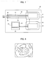
FIG. 1 is a block diagram schematically showing one example of the overall configuration of an endoscope apparatus of the invention. -
FIG. 2 is a block diagram showing signal processing systems of respective sections including the detailed configuration of the first embodiment of the endoscope apparatus shown inFIG. 1 . -
FIG. 3 is a graph showing emission spectra of a blue-violet laser beam (a 405 nm laser beam (A)) that is used for a light source device of the endoscope apparatus shown inFIG. 2 and is emitted from a blue-violet laser beam source, and emission spectra of white light (B) that is emitted from a white light source including a blue laser beam source and a fluorescent body. -
FIG. 4 shows an example of a captured image that is observed when the endoscope is inserted into and extracted from an alimentary canal, in the endoscope apparatus of the invention. -
FIG. 5A shows an example of changes of a frequency band filter when bandwidth is changed according to density or the like,FIG. 5B shows an example of changes of the frequency band filter when a central frequency is changed according to density or the like,FIG. 5C shows an example of changes of the frequency band filter when an enhanced frequency is changed according to density or the like, andFIG. 5D shows an example of changes of the frequency band filter in which one side is open. -
FIG. 6 is an example of a captured image when the frequency band filter is applied to the captured image shown inFIG. 4 . -
FIG. 7 is a flowchart showing one example of a flow until the irradiation light quantity is adjusted and a captured image signal is acquired again, in the endoscope observation carried out by the endoscope apparatus shown inFIG. 1 . -
FIG. 8 is a flowchart showing one example of a flow after a captured image signal is acquired again, in the endoscope observation in the first embodiment of the endoscope apparatus shown inFIG. 1 . -
FIG. 9 is a block diagram showing signal processing systems of respective sections including the detailed configuration of a second embodiment of the endoscope apparatus shown inFIG. 1 . -
FIG. 10 is a flowchart showing one example of a flow after a captured image signal is acquired again, in the endoscope observation in the second embodiment of the endoscope apparatus shown inFIG. 1 . -
FIG. 11 is a block diagram showing signal processing systems of respective sections including the detailed configuration of a third embodiment of the endoscope apparatus shown inFIG. 1 . -
FIG. 12 is a flowchart showing one example of a flow after a captured image signal is acquired again, in the endoscope observation in the third embodiment of the endoscope apparatus shown inFIG. 1 . -
FIG. 13 is a drawing of an extracted part when the block diagrams showing inFIGS. 2 ,9 , and11 include a low-frequency component extracting section. - An endoscope apparatus related to the invention will be described below in detail on the basis of preferred embodiments shown in the accompanying drawings.
-
FIG. 1 is a block diagram schematically showing one example of the overall configuration of the endoscope apparatus of the invention, andFIG. 2 is a block diagram showing signal processing systems of respective sections including the detailed configuration of a first embodiment of processors of the endoscope apparatus of the invention. - As shown in
FIG. 1 , theendoscope apparatus 10 of the invention has anendoscope 12, a light source device (constitutes the light source means of the invention along with afluorescent body 24 to be described below) 14, aprocessor 16, and an input andoutput section 18. Here, thelight source device 14 and theprocessor 16 constitute a control device of theendoscope 12, and theendoscope 12 is optically connected to thelight source device 14, and is electrically connected to theprocessor 16. Additionally, theprocessor 16 is electrically connected to the input andoutput section 18. The input/output section 18 has a display section (monitor) 38 that displays image information or the like as output, a recording device 42 (refer toFig. 2 ) that outputs image information or the like, and an input section (mode switching section) 40 that functions as a UI (user interface) that receives input operations, such as mode switching to a normal light mode, a special light mode, or the like, and function settings. - The
endoscope 12 is an electronic endoscope that has an illumination optical system that emits illumination light from the distal end thereof, and an imaging optical system that images a region to be observed. In addition, although not shown, theendoscope 12 includes an endoscope insertion part inserted into a subject, a manipulation part that performs curving manipulation of the distal end of the endoscope insertion part, and manipulation for observation, and connector parts that detachably connect theendoscope 12 to thelight source device 14 and theprocessor 16 of the control device. Moreover, although not shown, various channels, such as a forceps channel that allows a treatment tool or the like for tissue sampling to be inserted thereinto, and air supply and water supply channels, are provided inside the manipulation part and the endoscope insertion part. - As shown in
Fig. 1 , afluorescent body 24, of which the details will be described below and which constitutes the illumination optical system and a white light source, is provided in anirradiation port 28A that emits a region to be observed with light, at the distal end portion of theendoscope 12. An imaging element (sensor, imaging means of the invention) 26, which constitutes the imaging optical system, such as a CCD (Charge Coupled Device) image sensor or a CMOS (Complementary Metal-Oxide Semiconductor) image sensor that acquires the image information of a region to be observed, is arranged at a light-receiving part 28B adjacent to theirradiation port 28A. Additionally, a cover glass or a lens (not shown) that constitutes the illumination optical system is arranged at theirradiation port 28A of theendoscope 12, a cover glass or a lens (not shown) that constitutes the imaging optical system is arranged at the light-receiving part 28B, and an objective lens unit (not shown) that constitutes the imaging optical system is arranged at a light-receiving surface of theimaging element 26 of the light-receiving part 28B. - The endoscope insertion part is made curvable by the manipulation of the manipulation part, can be curved in arbitrary directions and at arbitrary angles according to the parts of a subject in which the
endoscope 12 is used, and can direct theirradiation port 28A and the light-receiving part 28B, that is, the observation direction of theimaging element 26, to a desired observation part. - In addition, although it is preferable that the
imaging element 26 be a color imaging sensor or a complementary-color sensor including a color filter (for example, an RGB color filter or a complementary-color filter) in a light-receiving region, the RGB color imaging sensor is more preferable. - Since the essence of the invention is not affected whether the invention is normal light observation or special light observation, it is not necessary to particularly limit the light source means as long as adjustment of the irradiation light quantity is possible. In addition, the
light source device 14 shown inFIG. 2 (FIGS. 9 and11 to be described below are also the same) has a blue laser beam source (445LD) 32 with a central wavelength of 445 nm to be used as a white light source, and a blue-violet laser beam source (405LD) 34 with a central wavelength of 405 nm to be used as a special light source in the special light mode as alight emission source 31. Hence, it is possible to radiate both the special light and the normal light, in cooperation with thefluorescent body 24 to be described below. - The
445LD 32 constitutes a first light source section of the invention, and the405LD 34 constitute a second light source section of the invention. In addition, since the blue-violet laser beam with a central wavelength of 405 nm from the405LD 34 is narrowband light with a wavelength bandwidth that is narrowbanded according to the spectral characteristics of the structure or components of a living body, preferably, in conformity with the characteristics, the detectability of the structure or components of the living body is excellent. - The light emission from the
445LD 32 and the405LD 34 is individually controlled by the light source control section 48 (refer toFIG. 2 ), and the light emission conditions of the445LD 32 and the405LD 34, that is, the light quantity ratio (light emission ratio) of the emitted light of the 445LD32 and the emitted light of the405LD 34 can be freely changed. - A broad area type InGaN-based laser diode can be used for the 445LD 32 and the
405LD 34, and an InGaNAs-based laser diode or a GaNAs-based laser diode can also be used. Additionally, the above light sources may be configured using light emitters, such as a light-emitting diode. - The laser beams emitted from the
445LD 32 and the405LD 34 are input tooptical fibers 22, respectively, by condensing lenses (not shown), and are transmitted to a connector part via a multiplexer (not shown). In addition, the invention is not limited thereto, and may have a configuration in which the laser beams from the respectivelight sources - A blue laser beam with a central wavelength of 445 nm and a blue-violet laser beam with a central wavelength of 405 nm are multiplexed, and a laser beam transmitted to the connector part is propagated to a distal end portion of the
endoscope 12 by theoptical fibers 22 that constitute the illumination optical system, respectively. Then, the blue laser beam excites thefluorescent body 24 arranged at light irradiation ends of theoptical fibers 22, at the distal end of theendoscope 12, thereby making the fluorescent body emit fluorescent light. Additionally, a portion of the blue laser beam transmits through thefluorescent body 24 as it is. The blue-violet laser beam transmits through thefluorescent body 24, whole hardly exciting the fluorescent body, and becomes illumination light (so-called narrowband light) with a narrowband wavelength. - The
optical fiber 22 is a multimode fiber, and a fine-diameter fiber cable whose core diameter is 105 µm, cladding diameter is 125 µm, and for which a diameter including a protective layer serving as an outer skin is φ0.3 to 0.5 mm can be used as an example. - The
fluorescent body 24 is configured so as to include a plurality of kinds of fluorescent bodies (for example, fluorescent bodies, such as a YAG-based fluorescent body or BAM (BaMgAl10O17)) that absorbs a portion of the blue laser beam, and is excited in green and yellow to emit light (emit fluorescent light). Thereby, green and yellow florescent light having the blue laser beam as excitation light, and the blue laser beam that is transmitted through thefluorescent body 24 without being absorbed thereby are combined, and become white (pseudo-white) illumination light. If the semiconductor light-emitting element is used as an excitation light source as the present embodiment, high-intensity white light can be obtained at high luminous efficiency, the intensity of the white light can be easily adjusted, and changes in color temperature and chromaticity of the white light can be suppressed to be low. - The
fluorescent body 24 can prevent the superposition of noise which becomes an obstacle to imaging or the occurrence of flickering when a moving image display is performed, due to a speckle caused by the coherency of a laser beam. Additionally, thefluorescent body 24 is preferably consisted of a fluorescent material and a filler material, and the grain sizes of the fluorescent material and of the filler material are determined such that 24 has a small absorption and large scattering of infrared light in consideration of the refractive index difference between the fluorescent material and a fixing/solidifying resin working as the filler material. Thereby, a scattering effect is enhanced without reducing light intensity with respect to red light or infrared light, and optical loss becomes small. -
Fig. 3 is a graph showing emission spectra of a blue-violet laser beam from the405LD 34, and emission spectra of a blue laser beam from the445LD 32 and a fluorescent light when the wavelength of a blue laser beam is converted by thefluorescent body 24. The blue-violet laser beam is expressed by an emission line (profile A) with a central wavelength of 405 nm, is the narrowband light of the invention, and is used mainly as special light (in the case of special light mixed with the white light, the special light constitutes a portion of the white light). Additionally, the blue laser beam is expressed by an emission line with a central wavelength of 445 nm, and excited and emitted light from thefluorescent body 24 caused by the blue laser beam has spectrum intensity distribution in which emission intensity increases in a wavelength band of approximately 450 nm to 700 nm. The above-described white light is formed by a profile B by the excited and emitted light and the blue laser beam, and is used mainly as normal light. - Here, the white light in the invention is not strictly limited to that including all the wavelength components of visible light and, for example, may include the light of a specific wavelength band, such as R, G, and B, including the above-described pseudo-white light. For example, the white light broadly includes the light including wavelength components from green to red, the light including wavelength components from blue to green, or the like.
- In the
endoscope apparatus 10, the emission intensities of the profile A and the profile B can be controlled so as to be relatively increased and decreased by the lightsource control section 48, to produce irradiation light with arbitrary luminance balance. In addition, in theendoscope apparatus 10 of the invention, in the normal light mode, only the light of the profile B is used and the light of superimposed profiles A and B is used in the special light mode. - As described above, illumination light including the white light (profile B) based on the blue laser beam from the
445LD 32 and the excited and emitted light from thefluorescent body 24, and the narrowband light (profile A) based on the blue-violet laser beam from the405LD 34 is emitted from theirradiation port 28A of the distal end portion of theendoscope 12 toward the region to be observed of a subject. The return light from a region to be observed that is irradiated with the illumination light is focused on the light-receiving surface of theimaging element 26 via the light-receiving part 28B, and the region to be observed is captured by theimaging element 26. - An image signal (captured image signal) of a captured image output from the
imaging element 26 after the imaging is input to animage processing system 36 of theprocessor 16 through ascope cable 30. - Next, the image signal of the captured image captured and output by the
imaging element 26 in this way is subjected to image processing in a signal processing system including theimage processing system 36 of theprocessor 16, is output to amonitor 38 or arecording device 42, and is provided for observation by the user. - Additionally, signal processing systems of respective sections including the detailed configuration of a processor of a first embodiment of the endoscope apparatus of the invention shown in
FIG. 2 will be described in detail. - As shown in this drawing, the signal processing system of the
endoscope apparatus 10 has a signal processing system of theendoscope 12, a signal processing system of thelight source device 14, a signal processing system (image processing system 36) of theprocessor 16, and themonitor 38, input section (mode switching section) 40 andrecording device 42 of the input andoutput section 18. - The signal processing system of the
endoscope 12 is a signal processing system for captured image signals from theimaging element 26, and has a CDS andAGC circuit 44 for performing correlated double sampling (CDS) or automatic gain control (AGC) on the captured image signals that are analog signals, and an A/D converter (A/D converter) 46 that converts analog image signals subjected to sampling and gain control in the CDS andAGC circuit 44 into digital image signals. The digital image signals that are A/D converted in the A/D converter 46 are input to theimage processing system 36 of theprocessor 16 via a connector part. - Additionally, the signal processing system of the
light source device 14 has a lightsource control section 48 that performs ON/OFF control and light quantity control of the445LD 32 and the405LD 34. - Here, the light
source control section 48 turns on the445LD 32 and the405LD 34 according to a light source ON signal accompanying the operation start of theendoscope apparatus 10, and performs the ON/OFF control of the405LD 34 according to the switching signal between the normal light mode and the special light mode from themode switching section 40. - Additionally, the light
source control section 48 controls the emission light quantity of the445LD 32 and the405LD 34, that is, the irradiation light quantity of the illumination light from thelight source device 14 by changing the emission intensities of the445LD 32 and the405LD 34, that is, the values of electric currents passed to thelight sources - Additionally, in principle, the light quantity of return light is calculated, for example, using a captured image signal of a predetermined portion (predetermined pixel) in a captured image in the light
quantity calculating section 50 to be described below such that an irradiation light quantity suitable for imaging is obtained, and the lightsource control section 48 controls thelight sources quantity calculating section 50 to be described below calculates information on automatic exposure in order to control the lightsource control section 48, and the automatic exposure (AE) is performed by the lightquantity calculating section 50 and the lightsource control section 48. - In addition, here, the information on the automatic exposure is a parameter for automatically determining the exposure during imaging, and is determined on the basis of the light quantity of the return light of the predetermined portion of the captured image detected by the
imaging element 26. Even in moving image imaging, the information on the automatic exposure is determined by the light quantity of the return light in the imaging time per frame that is settled according to the storage time (storage time of CCD or CMOS corresponding to an RGB color filter) of theimaging element 26. - Moreover, the signal processing system of the
processor 16 is the image processing system 36 (refer toFig. 1 ), and has a lightquantity calculating section 50, a DSP (digital signal processor) 52, adenoising circuit 54, a density calculating section (density calculating means of the invention), an image processing switching section 60, an image processing section (image processing means of the invention) 62, and an image displaysignal generating section 66. - The light
quantity calculating section 50 calculates the light quantity of return light received in the imaging element (sensor) 26, as mentioned above, using captured image signals input via a connector from the A/D converter 46 of theendoscope 12. - Additionally, the light
quantity calculating section 50 calculates light source light quantities, that is, the light quantity (emission intensity) of the blue laser beam from the445LD 32, the light quantity (spectrum intensity distribution shown by excited and emitted light) of the white light from thefluorescent body 24 based on this blue laser beam, and the light quantity (emission intensity of the blue-violet laser beam from the405LD 34, and the like, through the lightsource control section 48, and calculates the light quantity ratio (light emission ratio of 405LD/445LD) between the irradiation light quantity of the illumination light directed to a subject from thelight source device 14, and the 445LD 32 and the405LD 34 from these light quantities. - The light
quantity calculating section 50 controls the lightsource control section 48, using the light quantity of the return light and the irradiation light quantity that are calculated as mentioned above, as the aforementioned information on automatic exposure, and adjusts the white balance gain of the CDS/AGC circuit 44 from the light quantity ratio if required. - The
DSP 52 performs gamma correction and color correction processing on the digital image signals output from the A/D converter 46 after the irradiation light quantity and the light quantity of the return light is detected by the lightquantity calculating section 50. - The
denoising circuit 54 implements a denoising method in image processing, such as a moving-average method or a median filter method, and removes noise from the digital image signals subjected to the gamma correction and color correction processing in theDSP 52. - The digital image signals input to the
processor 16 from theendoscope 12 in this way are subjected to preprocessing, such as gamma correction, color correction processing, and denoising, in theDSP 52 and thedenoising circuit 54. - Next, the
density calculating section 55 calculates the density of each pixel of the captured image from the captured image signals that are denoised in thedenoising circuit 54. Specifically, for example, the density calculating section calculates the intensities of an R light image signal, a G light image signal, and a B light image signal in each pixel from the captured image shown inFIG. 4 , and sums up these intensities, thereby adopting the resulting value as the density of each pixel. - The
density calculating section 55 outputs the density of each pixel of the captured image to astructure enhancing section 74 of theimage processing section 62 to be described below as density information. - The image processing switching section 60 is a switch that switches whether the preprocessed digital image signals are sent to the color converter 68 of the
image processing section 62 in the subsequent stage or are sent to the special lightcolor conversion section 70 of theimage processing section 62, on the basis of the instruction (switching signal) of themode switching section 40 to be described below. - In addition, in the invention, for the purpose of distinction, digital image signals before image processing using the
image processing section 62 are referred to as image signals, and digital image signals before and after image processing are referred to as image data. - The
image processing section 62 is a section that performs image processing suitable for preprocessed digital image signals using the blue-violet laser beam (profile A) from the405LD 34, and the white light (profile B) from the445LD 32 and thefluorescent body 24, and has the color converter 68, the special lightcolor conversion section 70, thecolor enhancing section 72, and thestructure enhancing section 74. - The color converter 68 performs color conversion processing, such as matrix processing of 3x3, grayscale conversion processing, and three-dimensional LUT processing, on preprocessed RGB 3-channel digital image signals, and converts image signals into color-conversion-processed RGB image data.
- The special light
color conversion section 70 multiplies a G image signal of digital image signals of input preprocessed RGB3 channels by a predetermined coefficient to allocate the resulting value to R image data, and multiplies a B image signal by a predetermined coefficient to allocate the resulting values to G image data and B image data, respectively, thereby generating RGB image data, and then performs color conversion processing, such as 3x3 matrix processing, grayscale conversion processing, and three-dimensional LUT processing, on the generated RGB image data similarly to the color converter 68. - The
color enhancing section 72 is provided to give a difference in chroma between a blood vessel and a membrane in a screen, to enhance the blood vessel so that the blood vessel is clearly visible. For example, the average value of the chroma of the overall screen is checked with respect to the color-conversion-processed RGB image data, and enhancement processing is performed in a direction in which a difference is given to the chroma between the blood vessel and the membrane from the average value of the chroma. - The
structure enhancing section 74 performs structure enhancement processing, such as sharpness or contour enhancement, on the color-enhanced RGB image data. - Additionally, the
structure enhancing section 74 includes a frequencyband enhancing section 76, and performs frequency band enhancement processing on the color-enhanced RGB image data in the frequencyband enhancing section 76, on the basis of the density information of each pixel of the captured image from the aforementioneddensity calculating section 55, as a kind of the aforementioned structure enhancement processing. - The frequency enhancement processing of the frequency
band enhancing section 76 is performed by applying a predetermined frequency band filter to captured image data. By applying different frequency band filters according to the density of each pixel, better enhancement can be made so that a captured image corresponds to a purpose. - Additionally, a plurality of captured images obtained applying the different frequency band filters may be created, and the plurality of captured images may be synthesized according to the density of each pixel.
- A frequency band filter to apply may increase the bandwidth of a filter according to pixel density, for example, as shown in
FIG. 5A . For example, when the density is thick (dark), the bandwidth may be made wide, and when the density is thin (bright), the bandwidth may be made narrow. - Additionally, as shown in
FIG. 5B , the central frequency of a filter may be changed, according to pixel density. For example, when the density is thick, the central frequency may be made high, and when the density is thin, the central frequency may be made narrow. - Moreover, as shown in
FIG. 5C , the enhancement degree of a filter may be changed according to pixel density. For example, when the density is thick, the enhancement degree of a frequency enhancing filter may be weakened, and when the density is thin, the enhancement degree of the frequency enhancing filter may be strengthened. - The bandwidth, the central frequency, and the enhancement degree may be gradually changed or may be continuously changed according to the density.
- Additionally, these may be combined and changed. For example, when the density is thick, the bandwidth may be made wide, the central frequency may be made high, the enhancement degree may be made weak, and when the density is thin, the bandwidth may be made narrow, the central frequency may be made low, and the enhancement degree may be made strong.
- Additionally, as shown in
FIG. 5D , the frequency band filter may have one side open. Even in the filter ofFIG. 5D , similarly to the aforementionedFIGS. 5A to 5C , the enhancement degree may be changed or the frequency band may be moved. - In addition, the determination of low density, middle density, and high density with thin or thick density may be determined, for example, on the basis of the average value of pixel densities of the overall captured image, and the reference value of pixel densities may be provided in advance apart from the average value.
- As a specific example to which the frequency band filter is applied, in a captured image, it is considered that, in a region where the pixel density is a relatively low density, the distance between the distal end of the endoscope and a subject is sufficiently short, and enlarged observation is performed. Therefore, surface layer fine blood vessels can be assumed as a target to be captured, and a frequency band filter that can enhance a high-frequency portion is applied to the aforementioned RGB image data so that the fine structure of the surface layer fine blood vessels can be individually separated as fine lines.
- Additionally, for example, in a captured image, it is considered that, in a region where the pixel density is middle density, the distal end of the endoscope is slightly apart from a subject, and near-distance observation that requires a greater or smaller light quantity than that in the aforementioned enlarged observation is performed. Therefore, each of fine blood vessels slightly larger than the fine structure of surface layer fine blood vessels as a target to be captured can be assumed as a target to be captured, and a frequency enhancing filter that can enhance a middle-frequency portion is applied to the aforementioned RGB image data so that the atmosphere of the surface layer fine blood vessels can be enhanced.
- Moreover, in a captured image, it is considered that, in a region where the pixel density is high density, the distal end of the endoscope is apart from a subject, and far-distance observation that requires a larger quantity of light is performed. Therefore, a region called a brownish region where surface layer fine blood vessels are densely present as a lump rather than individual surface layer fine blood vessel can be assumed as a target to be captured.
- The region called a brownish region is assumed to be a region in an early-stage cancer, and many such regions have a size of about 1 mm, but some have a size of 2 mm or 3 mm. If a frequency band filter with narrow bandwidth, for example, is used, in order to enhance this frequency band, brownish regions outside the frequency band of this filter, even if only slightly outside, will not enhanced at all.
- Hence, in order to enhance all brownish regions with various sizes, it is desirable to use a frequency band filter in which the bandwidth is large or one side is greatly open.
- In the frequency
band enhancing section 76 of thestructure enhancing section 74, the RGB image data that has been subjected to optimal frequency enhancement processing is input to the image displaysignal generating section 66 from theimage processing section 62 as image-processed RGB image data, on the basis of the aforementioned density information for each pixel. - The image display
signal generating section 66 converts the image-processed RGB image data input from theimage processing section 62 into display image signals for being displayed as a soft copy image in themonitor 38 or for being output as a hard copy image in therecording device 42. - The
monitor 38 displays, as a soft copy image, a normal light observation image based on display image signals that are obtained in theimaging element 26 by the irradiation of white light and subjected to the preprocessing and the normal light image processing in theprocessor 16, in the normal light mode, and displays, as a soft copy image, a special light observation image based on display image signals that are obtained in theimaging element 26 by the irradiation of special light in addition to white light and subjected to the preprocessing and the special light image processing in theprocessor 16, in the special light mode. - A captured image as shown in
FIG. 6 to which a frequency band filter is applied according to pixel density that is subjected to the structure enhancement processing corresponding to a purpose is displayed on themonitor 38. - The
recording device 42 also outputs the normal light observation image obtained by the irradiation of white light as a hard copy image in the normal light mode, and outputs the special light observation image obtained by the irradiation of white light and special light as a hard copy image in the special light mode. - In addition, if required, the display image signals generated in the image display
signal generating section 66 may be recorded as image information in therecording device 42 including a memory or a storage device, though not shown. - On the other hand, the
mode switching section 40 has mode switching buttons for performing switching between the normal light mode and the special light mode, and a mode switching signal from themode switching section 40 is input to the lightsource control section 48 of thelight source device 14. Here, although themode switching section 40 is arranged as theinput section 40 of the input/output section 18, the mode switching section may be arranged at theprocessor 16, the manipulation part of theendoscope 12, or thelight source device 14. In addition, a switching signal from themode switching section 40 is output to the lightsource control section 48 and the image processing switching section 60. - The first embodiment of the endoscope apparatus of the invention is basically configured as described above.
- The operation of the first embodiment of the endoscope apparatus of the invention will be described below with reference to the flowchart of
FIGS. 7 and 8 . - The invention does not place restrictions on the normal light observation or the special light observation. Hence, for example, description will be made taking the case where the special light observation is performed as an example.
- In the present embodiment, first, normal light observation shall be performed in the normal light mode. That is, the
445LD 32 is turned on, and normal light image processing is performed on captured image data based on white light in theimage processing section 62. - Here, switching to the special light mode is performed by a user. A mode switching signal (special light ON) is output as the user manipulates the
mode switching section 40, and the image processing is switched to the special light mode in the image processing switching section 60. - Next, a mode switching signal is also input to the light
source control section 48 of thelight source device 14, the405LD 34 is turned on by the lightsource control section 48, and illumination light in which white light and narrowband light are mixed is emitted to a subject (S10). - The illumination light is reflected by the subject, and the return light thereof is acquired as captured image signals by the imaging element 26 (S12).
- Next, the captured image signals acquired by the
imaging element 26 have a white balance gain adjusted and are converted into digital data, and are then sent to the lightquantity calculating section 50. In the lightquantity calculating section 50, the light quantity of the return light is calculated on the basis of the captured image signals of a predetermined portion of the captured image (S14). - When the light quantity of the return light calculated in the light
quantity calculating section 50 is not within a predetermined range that is required for imaging, an instruction is issued to the lightsource control section 48 from the lightquantity calculating section 50, and adjustment of the irradiation light quantity is performed by the light source control section 48 (S16). When the light quantity of the return light is insufficient, an instruction of raising the irradiation light quantity is issued to the lightsource control section 48, and when the light quantity of the return light is excessively large, an instruction of lowering the irradiation light quantity is issued to the lightsource control section 48. - In addition, the light
quantity calculating section 50 also acquires information on the irradiation light quantity of thelight source device 14, that is, information on the emission light quantity of the445LD 32 and the 405LD 34 and the light quantity ratio thereof, from the lightsource control section 48. Additionally, the white balance gain of the CDS/AGC circuit 44 may be adjusted from the aforementioned information on the emission light quantity and the light quantity ratio, and the light quantity of the return light. - After the adjustment of the irradiation light quantity is performed, captured image signals are again acquired by the imaging element 26 (S18).
- If the captured image signals are acquired again, the
density calculating section 55 calculates the density of each pixel from an RGB image based on the captured image signals. The information on the density of each pixel calculated is output to the frequencyband enhancing section 76 of thestructure enhancing section 74 of the image processing section 62 (S20). - Then, image processing of the captured image data is changed on the basis of the density of each pixel calculated in the
density calculating section 55. The change of the image processing is performed by changing frequency processing conditions applied to the captured image data in thestructure enhancing section 74 of theimage processing section 62. - Specifically, in the frequency
band enhancing section 76 of thestructure enhancing section 74, a frequency band filter is set for each pixel according to the density of each pixel of the aforementioned captured image (S22). - The captured image data obtained in endoscope observation is output to the
image processing section 62, is subjected to the aforementioned image processing through the color converter 68 or the special lightcolor conversion section 70, and thecolor enhancing section 72, and is input to thestructure enhancing section 74. A frequency band filter that is set for each pixel as mentioned above is applied to the captured image data input to thestructure enhancing section 74, in the frequency band enhancing section 76 (S24). - In the
image processing section 62, a frequency enhancing filter according to the density of each pixel is applied, and the image-processed captured image data is output to the image displaysignal generating section 66. The image displaysignal generating section 66 generates and outputs image display signals from this image information. - The output image display signals are displayed on the
monitor 38 as an endoscope observation image, and are recorded by the recording device 42 (S26). - From the above, a captured image subjected to suitable frequency processing according to the density of each pixel can be displayed.
- The above is the operation of the first embodiment of the endoscope apparatus of the invention.
- Next, a second embodiment of the endoscope apparatus of the invention will be described focusing on differences from the first embodiment.
- The difference between the second embodiment of the endoscope apparatus of the invention and the first embodiment is that, when an enhanced frequency in image processing is set, the light quantity information (including the irradiation light quantity of illumination light, the light quantity of return light, the light quantity ratio thereof when there is a plurality of light sources, and the aforementioned information on automatic exposure) is calculated in the light
quantity calculating section 50 as well as the density information (the density of each pixel of a captured image), and the enhanced frequency is set by taking the light quantity information into consideration along with the density information. - Hence, the difference in apparatus configuration between the second embodiment and the first embodiment of the endoscope apparatus is that, as shown in
FIG. 9 , the light quantity information in captured image signals is output to thestructure enhancing section 74 from the lightquantity calculating section 50 along with the density information of each pixel from the aforementioneddensity calculating section 55. - In the frequency
band enhancing section 76 of thestructure enhancing section 74, setting of a frequency band filter is performed more precisely than the first embodiment, on the basis of the light quantity information from the lightquantity calculating section 50 and the density information from thedensity calculating section 55. - If the color of a subject is not taken into consideration, it is believed that the product of the "light quantity information" and the "density information (pixel value)" is proportional to the distance of each pixel of a captured image. Therefore, the setting of a frequency band filter that is more suitable than the first embodiment can be performed, and a captured image subjected to more suitable frequency processing can be obtained.
- The above are configurational differences between the first embodiment and the second embodiment of the invention.
- Additionally, the operation of the second embodiment of the endoscope apparatus of the invention will also be described focusing on the differences from the first embodiment.
- The operation of the second embodiment of the invention is the same regarding the steps shown in
FIG. 7 . The second embodiment implements the steps shown inFIG. 10 instead of the steps shown inFIG. 8 . - In
FIG. 10 , since Step S120 is the same as Step S20 ofFIG. 8 , the description thereof is omitted. - Additionally, in the invention, as mentioned above, the light
quantity calculating section 50 calculates the light quantity of return light from captured image signals, and the irradiation light quantity of illumination light (including the light quantity ratio when there is a plurality of light sources) from the lightsource control section 48, respectively, as the light quantity information (S115). - Next, the light quantity information of a captured image is acquired from the light
quantity calculating section 50, the density information of the captured image is acquired from thedensity calculating section 55, and a frequency band filter is set on the basis of the density information and the light quantity information in the frequency band enhancing section 76 (S122). A more suitable enhanced frequency can be set as compared to the first embodiment in which the setting of the enhanced frequency is performed only with the density information. - In addition, since Step S124 and Step S126 are the same as Step S24 and Step S26 of
FIG. 8 , the description thereof is omitted. - Thereby, a captured image subjected to suitable frequency processing according to the light quantity information and density information of the captured image can be displayed.
- The above is the second embodiment of the endoscope apparatus of the invention.
- Next, a third embodiment of the endoscope apparatus of the invention will be described focusing on differences from the second embodiment.
- The difference between the third embodiment of the endoscope apparatus of the invention and the second embodiment is that, when a frequency band filter in image processing is set, the distance of each pixel is estimated from the density information and the light quantity information, and a frequency band filter is set according to the distance of each pixel.
- Hence, the difference in apparatus configuration between the third embodiment and the second embodiment of the endoscope apparatus, as shown in
FIG. 11 , is that adistance estimating section 59 is included, light quantity information is output to thedistance estimating section 59 from the lightquantity calculating section 50 along with the density information of each pixel from the aforementioneddensity calculating section 55, the distance of each pixel is estimated from the light quantity information and the density information in thedistance estimating section 59. The information on the estimated distance of each pixel is output to the frequencyband enhancing section 76 of thestructure enhancing section 74, and a frequency band filter is set according to the distance of each pixel in the frequencyband enhancing section 76. - Here, the distance of each pixel means the distance from the distal end of the endoscope to a subject portion corresponding to each pixel.
- As for estimation of the distance of each pixel in the
distance estimating section 59, first, the distance to a predetermined pixel (predetermined portion) in a captured image is first estimated using light quantity information. Here, the light quantity information is the light quantity of the return light of a predetermined portion in a captured image signal that is the control information of AE, and is information including the ratio of the irradiation light quantity of illumination light, and the light quantity of return light. Since no light sources other than the illumination light that the endoscope itself irradiates are present in the endoscope observation, the distance to a subject (predetermined portion) can be estimated from the irradiation light quantity of illumination light and the light quantity of return light. - Next, in a captured image, the density difference between a predetermined pixel whose distance is estimated, and other pixels is calculated according to the density of each pixel mentioned above. The distance of each pixel can be estimated with a predetermined pixel as a reference, on the basis of the density difference between a predetermined pixel and other pixels.
- The distance of each pixel estimated in the
distance estimating section 59 is output to the frequencyband enhancing section 76 of thestructure enhancing section 74. - In the frequency
band enhancing section 76 of thestructure enhancing section 74, a frequency band filter is set according to the estimated distance of each pixel. - Although the setting of a frequency band filter is the same as that of the first embodiment and the second embodiment, a higher-precision frequency band filter can be set. The above are the configurational differences of the third embodiment of the endoscope apparatus.
- Additionally, the operation of the third embodiment of the endoscope apparatus of the invention will also be described focusing on the differences from the second embodiment.
- The operation of the third embodiment of the invention is the same regarding the steps shown in
FIG. 7 . The third embodiment takes the steps shown inFIG. 12 instead of the steps shown inFIG. 10 of the second embodiment. - In
FIG. 12 , Steps S215, S220, S224, and S226 are the same as Steps S115, S120, S124, and S126 ofFIG. 10 . Hence, the description thereof is omitted. The differences between the third embodiment and the second embodiment are Step S122, and Step S221 and Step S223. - In the invention, as mentioned above, first, the aforementioned light quantity information is acquired from the light
quantity calculating section 50, the density information of a captured image is acquired from thedensity calculating section 55, and the distance of each pixel in the captured image is estimated on the basis of the density information and the light quantity information in the distance estimating section 59 (S221). - The distance of each pixel estimated in the
distance estimating section 59 is output to thestructure enhancing section 74, and a frequency band filter is set on the basis of the distance of each estimated pixel in the frequencyband enhancing section 76 of the structure enhancing section 74 (S223). By estimating the distance of each pixel and setting a frequency band filter according to distance, a higher-precision frequency band filter can be set as compared to the first embodiment and the second embodiment. - The above is the endoscope apparatus related to the third embodiment of the invention.
- In addition, as shown in
FIG. 13 , in the first to third embodiments, a low-frequency component extracting section (low-frequency component extracting means of the invention) 57 that extracts the low-frequency component of a captured image signal may be provided before thedensity calculating section 55, and the density information of each pixel of a captured image may be calculated on the basis of a low-frequency image signal extracted by the low-frequencycomponent extracting section 57. By extracting the low-frequency component to create an image, a captured image in which a blood vessel portion is enhanced can be obtained. - Although the endoscope apparatus of the invention has been described in detail above, the invention is not limited to the above embodiments, and various improvements and modifications may be performed without departing from the scope of the invention.
Claims (10)
- An endoscope apparatus comprising:light source means that is capable of adjusting quantity of light and irradiates illumination light to a subject;imaging means that captures a capturing image by return light from a living body that is the subject in the illumination light and outputs a captured image signal;density calculating means that calculates density of each pixel of the captured image on basis of the captured image signal; andimage processing means that performs a predetermined image processing on the captured image,wherein the image processing means changes frequency processing conditions with respect to the captured image such that detection and enhancement degree of a structure and components of the living body in the subject are changed according to at least the density of each pixel of the captured image.
- The endoscope apparatus according to claim 1, wherein the image processing means includes a frequency band enhancing section that enhances a predetermined frequency band, and the frequency band enhancing section changes the frequency band to be enhanced according to the density of each pixel of the captured image.
- The endoscope apparatus according to claim 2, wherein the frequency band enhancing section weakens the enhancement degree as the density becomes large, and strengthens the enhancement degree as the density becomes small.
- The endoscope apparatus according to claim 2 or 3, wherein the frequency band enhancing section changes bandwidth of the frequency band to be enhanced according to the density of each pixel of the captured image.
- The endoscope apparatus according to any one of claims 2 to 4, wherein the frequency band enhancing section changes a center of the frequency band to be enhanced, according to the density of each pixel of the captured image.
- An endoscope apparatus comprising:light source means that is capable of adjusting quantity of light and irradiates illumination light to a subject;imaging means that captures a capturing image by return light from a living body that is the subject in the illumination light and outputs a captured image signal;density calculating means that calculates density of each pixel of the captured image on basis of the captured image signal;light quantity calculating means that calculates light quantity information including light quantity of the illumination light, and the light quantity of the return light obtained from the captured image signal of a predetermined portion of the captured image; andimage processing means that performs a predetermined image processing on the captured image,wherein the image processing means changes frequency processing conditions with respect to the captured image such that detection and enhancement degree of a structure and components of the living body in the subject are changed according to the density of each pixel of the captured image and the light quantity information.
- The endoscope apparatus according to claim 6, wherein the image processing means includes a distance estimating section, and
the distance estimating section estimates the distance of each pixel of the captured image on the basis of the density of each pixel on the captured image and the light quantity information, and changes the frequency processing conditions with respect to the captured image according to the distance of each pixel of the captured image. - The endoscope apparatus according to claim 7, wherein the image processing means includes a frequency band enhancing section that enhances a predetermined frequency band, and
the frequency band enhancing section changes the frequency band to be enhanced according to the distance of each pixel of the captured image. - The endoscope apparatus according to any one of claims 1 to 8, further comprising low-frequency component extracting means that extracts a low-frequency component of the captured image from the captured image signal to generate a low-frequency captured image, and outputs a low-frequency captured image signal,
wherein the low-frequency captured image signal is used instead of the captured image signal in the density calculating means. - The endoscope apparatus according to any one of claims 1 to 9, wherein the light source means includes
a first light source section that emits broadband light having a wide wavelength band including a visible region,
a second light source section that emits narrowband light having a wavelength bandwidth narrowbanded according to spectral characteristics of the structure and components of the living body used as the subject, and
a light source control section that controls light emission, irradiation light quantity, and a light quantity ratio from the first light source section and the second light source section.
Applications Claiming Priority (1)
| Application Number | Priority Date | Filing Date | Title |
|---|---|---|---|
| JP2011038269A JP5335017B2 (en) | 2011-02-24 | 2011-02-24 | Endoscope device |
Publications (2)
| Publication Number | Publication Date |
|---|---|
| EP2491851A2 true EP2491851A2 (en) | 2012-08-29 |
| EP2491851A3 EP2491851A3 (en) | 2013-04-24 |
Family
ID=45557938
Family Applications (1)
| Application Number | Title | Priority Date | Filing Date |
|---|---|---|---|
| EP12153222.0A Withdrawn EP2491851A3 (en) | 2011-02-24 | 2012-01-31 | Endoscope apparatus |
Country Status (3)
| Country | Link |
|---|---|
| US (1) | US9072453B2 (en) |
| EP (1) | EP2491851A3 (en) |
| JP (1) | JP5335017B2 (en) |
Cited By (2)
| Publication number | Priority date | Publication date | Assignee | Title |
|---|---|---|---|---|
| CN105705075A (en) * | 2013-10-28 | 2016-06-22 | 富士胶片株式会社 | Image processing device and working method thereof |
| EP2775450A3 (en) * | 2013-03-06 | 2017-08-09 | Fujifilm Corporation | Image processing device and method for operating endoscope system |
Families Citing this family (9)
| Publication number | Priority date | Publication date | Assignee | Title |
|---|---|---|---|---|
| JP5677378B2 (en) * | 2012-07-25 | 2015-02-25 | 富士フイルム株式会社 | Endoscope system |
| WO2015005277A1 (en) * | 2013-07-11 | 2015-01-15 | オリンパスメディカルシステムズ株式会社 | Light source device |
| JP6206691B2 (en) * | 2014-03-31 | 2017-10-04 | 富士フイルム株式会社 | Endoscope system and operating method thereof |
| WO2016084608A1 (en) | 2014-11-25 | 2016-06-02 | ソニー株式会社 | Endoscope system, method for operating endoscope system, and program |
| WO2017221353A1 (en) * | 2016-06-22 | 2017-12-28 | オリンパス株式会社 | Image processing device, method for operating image processing device, and program for operating image processing device |
| CN105962881A (en) * | 2016-07-26 | 2016-09-28 | 西安交通大学第附属医院 | Blood vessel recognition method and device |
| EP3698702B1 (en) * | 2017-10-17 | 2023-06-07 | FUJIFILM Corporation | Medical image processing device and endoscope device |
| JP2022012599A (en) * | 2020-07-02 | 2022-01-17 | ソニーグループ株式会社 | Medical system, information processing device and information processing method |
| JP7074817B2 (en) * | 2020-09-09 | 2022-05-24 | 西日本電信電話株式会社 | Vital data measuring device, vital data measuring method and computer program |
Family Cites Families (16)
| Publication number | Priority date | Publication date | Assignee | Title |
|---|---|---|---|---|
| JPH02202175A (en) * | 1989-01-30 | 1990-08-10 | Dainippon Screen Mfg Co Ltd | Sharpness emphasizing method for picture scanning and recording device |
| JP3247201B2 (en) * | 1993-06-01 | 2002-01-15 | オリンパス光学工業株式会社 | Endoscope device |
| JPH10290779A (en) * | 1997-04-17 | 1998-11-04 | Olympus Optical Co Ltd | Electronic endoscope device |
| JP4370008B2 (en) * | 1998-11-17 | 2009-11-25 | オリンパス株式会社 | Endoscopic image processing device |
| JP2001008097A (en) * | 1999-06-22 | 2001-01-12 | Fuji Photo Optical Co Ltd | Electronic endoscope |
| KR20020035588A (en) * | 1999-09-08 | 2002-05-11 | 기시모토 마사도시 | Image pickup optical system for endoscope |
| JP3559755B2 (en) | 2000-07-27 | 2004-09-02 | オリンパス株式会社 | Endoscope device |
| JP3607857B2 (en) | 2000-07-27 | 2005-01-05 | オリンパス株式会社 | Endoscope device |
| US7892169B2 (en) | 2000-07-21 | 2011-02-22 | Olympus Corporation | Endoscope apparatus |
| JP2002300402A (en) * | 2001-03-30 | 2002-10-11 | Fuji Photo Film Co Ltd | Image processor, processing method and recording medium |
| JP4411879B2 (en) * | 2003-07-01 | 2010-02-10 | 株式会社ニコン | Signal processing apparatus, signal processing program, and electronic camera |
| JP5461753B2 (en) * | 2004-07-30 | 2014-04-02 | オリンパス株式会社 | Endoscope device |
| US20090091614A1 (en) * | 2005-05-13 | 2009-04-09 | Olympus Medical Systems Corp. | Biological observation apparatus |
| JP5057675B2 (en) | 2006-03-03 | 2012-10-24 | オリンパスメディカルシステムズ株式会社 | Living body observation device |
| JP5401205B2 (en) | 2009-08-10 | 2014-01-29 | 富士フイルム株式会社 | Endoscope device |
| KR101689867B1 (en) * | 2010-09-15 | 2016-12-27 | 삼성전자주식회사 | Method for processing image, image processing apparatus and medical image system for performing the same |
-
2011
- 2011-02-24 JP JP2011038269A patent/JP5335017B2/en active Active
-
2012
- 2012-01-26 US US13/359,440 patent/US9072453B2/en not_active Expired - Fee Related
- 2012-01-31 EP EP12153222.0A patent/EP2491851A3/en not_active Withdrawn
Non-Patent Citations (1)
| Title |
|---|
| None |
Cited By (2)
| Publication number | Priority date | Publication date | Assignee | Title |
|---|---|---|---|---|
| EP2775450A3 (en) * | 2013-03-06 | 2017-08-09 | Fujifilm Corporation | Image processing device and method for operating endoscope system |
| CN105705075A (en) * | 2013-10-28 | 2016-06-22 | 富士胶片株式会社 | Image processing device and working method thereof |
Also Published As
| Publication number | Publication date |
|---|---|
| US9072453B2 (en) | 2015-07-07 |
| JP2012170770A (en) | 2012-09-10 |
| EP2491851A3 (en) | 2013-04-24 |
| US20120220824A1 (en) | 2012-08-30 |
| JP5335017B2 (en) | 2013-11-06 |
Similar Documents
| Publication | Publication Date | Title |
|---|---|---|
| US9072453B2 (en) | Endoscope apparatus | |
| JP5371920B2 (en) | Endoscope device | |
| US9179074B2 (en) | Endoscope device | |
| US8970685B2 (en) | Endoscope apparatus | |
| JP5460506B2 (en) | Endoscope apparatus operating method and endoscope apparatus | |
| JP5460507B2 (en) | Endoscope apparatus operating method and endoscope apparatus | |
| CN106388756B (en) | Image processing apparatus, method of operating the same, and endoscope system | |
| JP5450527B2 (en) | Endoscope device | |
| EP2465432B1 (en) | Endoscope apparatus | |
| JP5331904B2 (en) | Endoscope system and method for operating endoscope system | |
| CN105101863B (en) | Image processing apparatus | |
| JP5485215B2 (en) | Endoscope device | |
| CN105101862A (en) | Image processing device and working method of endoscope system | |
| JP2013202167A (en) | Image processing device and endoscope system | |
| JP2012050641A (en) | Endoscope system | |
| EP2924971B1 (en) | Medical image processing device and method for operating the same | |
| JP5538143B2 (en) | Endoscope system | |
| JP2016174976A (en) | Endoscope system | |
| JP5677555B2 (en) | Endoscope device | |
| JP6454755B2 (en) | Endoscope system | |
| JP5965028B2 (en) | Endoscope system | |
| JP5827720B2 (en) | Endoscope system |
Legal Events
| Date | Code | Title | Description |
|---|---|---|---|
| PUAI | Public reference made under article 153(3) epc to a published international application that has entered the european phase |
Free format text: ORIGINAL CODE: 0009012 |
|
| AK | Designated contracting states |
Kind code of ref document: A2 Designated state(s): AL AT BE BG CH CY CZ DE DK EE ES FI FR GB GR HR HU IE IS IT LI LT LU LV MC MK MT NL NO PL PT RO RS SE SI SK SM TR |
|
| AX | Request for extension of the european patent |
Extension state: BA ME |
|
| RIC1 | Information provided on ipc code assigned before grant |
Ipc: A61B 1/05 20060101ALN20130111BHEP Ipc: A61B 1/06 20060101AFI20130111BHEP Ipc: A61B 1/00 20060101ALI20130111BHEP |
|
| PUAL | Search report despatched |
Free format text: ORIGINAL CODE: 0009013 |
|
| AK | Designated contracting states |
Kind code of ref document: A3 Designated state(s): AL AT BE BG CH CY CZ DE DK EE ES FI FR GB GR HR HU IE IS IT LI LT LU LV MC MK MT NL NO PL PT RO RS SE SI SK SM TR |
|
| AX | Request for extension of the european patent |
Extension state: BA ME |
|
| RIC1 | Information provided on ipc code assigned before grant |
Ipc: A61B 1/05 20060101ALN20130319BHEP Ipc: A61B 1/06 20060101AFI20130319BHEP Ipc: A61B 1/00 20060101ALI20130319BHEP |
|
| 17P | Request for examination filed |
Effective date: 20131022 |
|
| RBV | Designated contracting states (corrected) |
Designated state(s): AL AT BE BG CH CY CZ DE DK EE ES FI FR GB GR HR HU IE IS IT LI LT LU LV MC MK MT NL NO PL PT RO RS SE SI SK SM TR |
|
| STAA | Information on the status of an ep patent application or granted ep patent |
Free format text: STATUS: THE APPLICATION HAS BEEN WITHDRAWN |
|
| 18W | Application withdrawn |
Effective date: 20150804 |