EP2491848A1 - Endoscope having end nozzle - Google Patents
Endoscope having end nozzle Download PDFInfo
- Publication number
- EP2491848A1 EP2491848A1 EP12153364A EP12153364A EP2491848A1 EP 2491848 A1 EP2491848 A1 EP 2491848A1 EP 12153364 A EP12153364 A EP 12153364A EP 12153364 A EP12153364 A EP 12153364A EP 2491848 A1 EP2491848 A1 EP 2491848A1
- Authority
- EP
- European Patent Office
- Prior art keywords
- disposed
- window area
- endoscope
- head assembly
- recess
- Prior art date
- Legal status (The legal status is an assumption and is not a legal conclusion. Google has not performed a legal analysis and makes no representation as to the accuracy of the status listed.)
- Granted
Links
Images






Classifications
-
- A—HUMAN NECESSITIES
- A61—MEDICAL OR VETERINARY SCIENCE; HYGIENE
- A61B—DIAGNOSIS; SURGERY; IDENTIFICATION
- A61B1/00—Instruments for performing medical examinations of the interior of cavities or tubes of the body by visual or photographical inspection, e.g. endoscopes; Illuminating arrangements therefor
- A61B1/12—Instruments for performing medical examinations of the interior of cavities or tubes of the body by visual or photographical inspection, e.g. endoscopes; Illuminating arrangements therefor with cooling or rinsing arrangements
- A61B1/126—Instruments for performing medical examinations of the interior of cavities or tubes of the body by visual or photographical inspection, e.g. endoscopes; Illuminating arrangements therefor with cooling or rinsing arrangements provided with means for cleaning in-use
-
- A—HUMAN NECESSITIES
- A61—MEDICAL OR VETERINARY SCIENCE; HYGIENE
- A61B—DIAGNOSIS; SURGERY; IDENTIFICATION
- A61B1/00—Instruments for performing medical examinations of the interior of cavities or tubes of the body by visual or photographical inspection, e.g. endoscopes; Illuminating arrangements therefor
- A61B1/00064—Constructional details of the endoscope body
- A61B1/00071—Insertion part of the endoscope body
- A61B1/0008—Insertion part of the endoscope body characterised by distal tip features
-
- A—HUMAN NECESSITIES
- A61—MEDICAL OR VETERINARY SCIENCE; HYGIENE
- A61B—DIAGNOSIS; SURGERY; IDENTIFICATION
- A61B1/00—Instruments for performing medical examinations of the interior of cavities or tubes of the body by visual or photographical inspection, e.g. endoscopes; Illuminating arrangements therefor
- A61B1/00064—Constructional details of the endoscope body
- A61B1/00071—Insertion part of the endoscope body
- A61B1/0008—Insertion part of the endoscope body characterised by distal tip features
- A61B1/00091—Nozzles
Definitions
- the present invention relates to an endoscope having an end nozzle. More particularly, the present invention relates to an endoscope having an end nozzle, in which an imaging window area is washed, and plural lighting window areas can be protected from sticking of dirt or other unwanted fluid.
- An endoscope includes a section of an elongated tube, a head assembly, an imaging window area, lighting window areas, and an end nozzle device.
- the head assembly is entered in a body cavity of a body for imaging.
- the imaging window area, the lighting window areas and the end nozzle device are disposed in the head assembly.
- the imaging window area receives image light from the body.
- the lighting window areas emit light to the body.
- the end nozzle device ejects washing fluid such as water and air to the imaging window area.
- a first surface is defined on a distal side of the elongated tube, and is perpendicular to an axial direction of the elongated tube.
- the imaging window area and the end nozzle device are disposed on the first surface.
- the lighting window areas are arranged so that the imaging window area is surrounded by the lighting window areas.
- a window surface of the imaging window area is kept flush with the first surface of the elongated tube.
- Body fluid or dirt in the body is likely to stick on the window surface of the imaging window area.
- Use of the end nozzle device is disclosed in JP-B 3583542 (corresponding to JP-A 9-238893 ), U.S. Pat. No. 6,409, 657 (corresponding to JP-A 2000-279370 ), and EP-A 2011428 (corresponding to JP-A 2007-289355 and U.S. Pat. Pub. No. 2009/048,490 ).
- a nozzle opening in the end nozzle device ejects water to wash away the dirt from the imaging window area. Also, air is ejected through the nozzle opening to blow away droplets of water from the window surface of the imaging window area.
- the body fluid or dirt from the body is present on the window surface of the lighting window areas in addition to the window surface of the imaging window area.
- the lighting window areas are washed sometimes but less frequently than the imaging window area is. If the dirt stuck on the window surface of the lighting window areas becomes increased, a light amount of light applied to the body decreases to cause difficulty in the imaging. If a light source apparatus having a light adjuster is used, the light adjuster automatically operates to increase the light amount of the light in response to a decrease in the brightness in the body according to the dirt of the lighting window areas in the endoscope. Problems arise in that walls of the head assembly of the endoscope may be degraded by overheat, and that the dirt may be dried and stuck on the lighting window areas in an unremovable manner.
- JP-B 3583542 (corresponding to JP-A 9-238893 ) and U.S. Pat. No. 6,409,657 (corresponding to JP-A 2000-279370 ) disclose only washing of the imaging window area.
- the washing fluid ejected by the end nozzle device impinges on the imaging window area to remove the dirt, but does not impinge on the lighting window areas. No removal of the dirt from the lighting window areas is suggested.
- EP-A 2011428 (corresponding to JP-A 2007-289355 and U.S. Pat. Pub. No. 2009/048,490 )
- one of the lighting window areas is disposed near to a position in a path direction of the end nozzle device, and may be washed. However, remaining ones of the lighting window areas are disposed away from the path direction of the washing fluid from the end nozzle device.
- an object of the present invention is to provide an endoscope having an end nozzle, in which an imaging window area is washed, and plural lighting window areas can be protected from sticking of dirt or other unwanted fluid.
- an endoscope having a section of an elongated tube for entry in a body cavity.
- a first surface is formed at a distal end of a head assembly included in the elongated tube, and disposed to extend crosswise to an axial direction of the elongated tube.
- a recess is formed in the head assembly at a lower level than the first surface.
- At least one lighting window area is disposed in the recess, for applying light to an object in the body cavity.
- An imaging window area is disposed in the first surface, for receiving light from the object.
- An end nozzle is disposed on the first surface, for washing the imaging window area by ejecting washing fluid thereto.
- a distal projection is formed on the head assembly at a higher level than the first surface, for receiving the washing fluid from the imaging window area.
- a surface height of the imaging window area is larger than a height of the first surface.
- the recess is annular and tapered, and disposed to surround the lighting window area.
- the recess extends continuously with the distal projection.
- the distal projection extends at least partially along an outer surface of the head assembly.
- the recess is disposed between a periphery of the imaging window area and the distal projection, is in an arcuate shape, and has a second surface where the lighting window area is disposed.
- an inclined guide surface is disposed to extend continuously between the first and second surfaces.
- the guide surface is disposed along a periphery of the imaging window area.
- an endoscope includes a section of an elongated tube, having a head assembly, for entry in a body cavity in a body.
- a first surface is disposed at a distal end of the head assembly in an axial direction of the elongated tube.
- Plural lighting window areas are formed in the first surface, for applying light to an object in the body cavity.
- An imaging window area is formed in the first surface, for receiving object light from the object.
- An end nozzle device is disposed on the head assembly, for washing the imaging window area by blowing washing fluid thereto.
- a distal projection is disposed to project from the first surface in the axial direction, for receiving the washing fluid ejected from the end nozzle device toward the imaging window area.
- a recess is formed in the first surface, disposed on a periphery of the lighting window areas, for directing the washing fluid to the lighting window areas.
- the end nozzle device includes a flow conduit, disposed in the head assembly, for supplying the washing fluid in the axial direction.
- a nozzle spout is formed at a distal end of the flow conduit, for directing the washing fluid from the flow conduit toward the imaging window area on the first surface.
- the recess is disposed annularly to surround each of the plural lighting window areas with an inclination between the first surface and the lighting window areas in a cup shape.
- the recess includes an annular region disposed around each of the lighting window areas.
- An extension region is formed to extend along the distal projection from the annular region, for introducing the washing fluid from the distal projection into the annular region.
- An inner surface of the recess is continuous with a surface of the distal projection.
- the recess is in an arcuate shape, and the plural lighting window areas are contained in a profile of the recess.
- the distal projection is in a circumferential shape, and disposed to surround the first surface.
- the distal projection is in an arcuate shape, and the recess is formed to extend along the distal projection.
- the recess includes a second surface formed to extend substantially flatly, and having a profile containing the plural lighting window areas.
- a guide surface is inclined from the second surface toward the first surface with respect to the axial direction.
- the distal projection includes a center portion disposed to project from the first surface at predetermined height.
- First and second end portions are disposed at respectively lateral sides of the center portion, and having an inclined surface inclined at a height increasing from the first surface toward the center portion.
- first and second fluid ports are disposed at respectively lateral ends of the distal projection, formed to retreat from the first surface by extending the recess to an outer surface of the head assembly, for exiting the washing fluid from the recess.
- a guide surface is formed with an edge of the recess and inclined toward the first surface.
- a second surface is formed to extend substantially flatly, and having a profile containing the plural lighting window areas.
- a wall projection is disposed to surround each of the lighting window areas and to project from the second surface.
- An inclined surface is formed on the wall projection, and inclined with a decreasing height toward the second surface.
- the distal projection is in an arcuate shape, and the recess is formed to extend along the distal projection.
- the plural lighting window areas can be protected from sticking of dirt or other unwanted fluid, because the distal projection receives the washing fluid reliably and the lighting window areas can be protected by collecting the washing fluid.
- an electronic endoscope system 11 includes an electronic endoscope 12, a processing apparatus 13, a light source apparatus 14 and a fluid supply source 15.
- the fluid supply source 15 includes an air pump 15a for air supply, and a water reservoir 15b or a tank for washing.
- the air pump 15a is a well-known device, is incorporated in the light source apparatus 14, and supplies air.
- the water reservoir 15b is separate from the light source apparatus 14, and stores water as washing fluid.
- the endoscope 12 includes a section of an elongated tube 16, a handle device 17, a connector plug 18 and a universal cable 19.
- the elongated tube 16 is flexible and entered in a body of a patient.
- the handle device 17 is connected with a proximal end of the elongated tube 16.
- the connector plug 18 is plugged with the processing apparatus 13 and the light source apparatus 14.
- the universal cable 19 extends between the handle device 17 and the connector plug 18.
- the connector plug 18 is a composite type to which the processing apparatus 13, the light source apparatus 14
- the elongated tube 16 includes a head assembly 16a, a steering device 16b, and a flexible tube 16c.
- a CCD 39 or image sensor of Fig. 2 is incorporated in the head assembly 16a.
- the steering device 16b is disposed at a proximal end of the head assembly 16a for steering.
- the flexible tube 16c is disposed at a proximal end of the steering device 16b.
- the processing apparatus 13 is connected with the light source apparatus 14, and controls functions of the endoscope system 11.
- the processing apparatus 13 supplies the endoscope 12 with power through a cable extending through the universal cable 19 and the elongated tube 16, and controls the CCD 39.
- the processing apparatus 13 receives an image signal from the CCD 39 through the cable, and creates image data by image processing of the image signal.
- a monitor display panel 20 is driven by means of the cable from the processing apparatus 13 to display an image according to the image data created by the processing apparatus 13.
- a fluid channel 21 is formed through the elongated tube 16 and the handle device 17.
- An end nozzle device 22 (end nozzle) is incorporated in the head assembly 16a, and has a nozzle opening with which the fluid channel 21 communicates. See Figs. 2-4 .
- the fluid channel 21 extends through the universal cable 19 and is connected with the fluid supply source 15.
- the handle device 17 includes a proximal instrument opening 23, a fluid supply button 24 and steering wheels 25.
- the proximal instrument opening 23 receives entry of any of various medical instruments, such as an injection needle, electrocautery device of high frequency and the like.
- air generated by the air pump 15a is caused to flow to the end nozzle device 22.
- water as washing fluid in the water reservoir 15b is caused to flow to the end nozzle device 22 by pressure of the air from the air pump 15a.
- the end nozzle device 22 selectively ejects air or the washing fluid from the fluid channel 21.
- control wires in the elongated tube 16 are moved back and forth to steer the steering device 16b up or down or to the right or left.
- the head assembly 16a is bent in a desired direction in a body cavity.
- the elongated tube 16 includes an end shell 26, a head cap 27, an imaging window area 28 or window unit, lighting window areas 29a and 29b or window units, and a distal instrument opening 30, as well as the end nozzle device 22.
- the end shell 26 includes mount holes 26a, 26b and 26c formed through in the axial direction of the elongated tube 16.
- a lens system 35 or objective lens is mounted in the mount hole 26a as will be described later.
- the end nozzle device 22 is mounted in the mount hole 26b.
- a light guide device 40 is mounted in each of the mount holes 26c.
- the head cap 27 includes a cap plate 27a and a cap skirt 27b projecting from the cap plate 27a to extend on an outer surface of the end shell 26.
- An outer tube 32 covers the steering device 16b, extends toward the end shell 26.
- a distal end of the outer tube 32 is engaged with a proximal end of the cap skirt 27b, and attached thereto by use of adhesive agent or the like.
- a first surface 33 or end surface (tip surface) is located on the cap plate 27a, is flat and perpendicular to an axial direction of the elongated tube 16, and is positioned on a distal side of the head assembly 16a.
- the cap plate 27a has through openings 27c, 27d and 27e.
- the through opening 27c is disposed in a portion near to the center of the head assembly 16a as viewed in the axial direction, and is an aperture for the imaging window area 28.
- the through openings 27d and 27e are apertures for the lighting window areas 29a and 29b, and are arranged symmetrically with respect to the through opening 27c.
- a through hole 27f and the distal instrument opening 30 are formed in the first surface 33.
- the through hole 27f is a mount hole for the end nozzle device 22.
- the imaging window area 28 is constituted by a window lens or objective lens as an element of the lens system 35 on the distal side, and also functions as a cover of glass.
- the window lens is in a circular shape, and has a window surface 28a and a peripheral surface 28b around the window surface 28a.
- a lens barrel 36 includes the lens system 35 as optical system aligned with the imaging window area 28.
- the lens barrel 36 is engaged with a proximal edge of the peripheral surface 28b of the imaging window area 28.
- a distal edge of the peripheral surface 28b of the imaging window area 28 is engaged with the through opening 27c of the head cap 27.
- the lens barrel 36 is fitted in the mount hole 26a of the end shell 26.
- a distal surface of the lens barrel 36 tightly contacts the cap plate 27a of the head cap 27.
- the imaging window area 28 is disposed to set the window surface 28a at a predetermined height from the first surface 33.
- An annular projection 37 is formed on the head cap 27, is disposed between the edge of the window surface 28a and the first surface 33, and projects at a predetermined height from the first surface 33.
- the annular projection 37 has an inner surface where the through opening 27c is defined.
- An inclined surface 38 is formed around the annular projection 37, and has a height gradually decreasing from the window surface 28a toward the first surface 33.
- the CCD 39 is disposed on a proximal side of the lens system 35.
- An example of the CCD 39 is an interline transfer CCD.
- An object image is focused on an imaging surface of the CCD 39 according to object light entered through the lens system 35.
- an image sensor can be a CMOS image sensor in place of the CCD 39.
- the lighting window areas 29a and 29b are constituted by window lenses, and emit light from the light source apparatus 14 toward an object of interest in a body cavity.
- a distal surface of the lighting window areas 29a and 29b is positioned lower than the first surface 33 in the proximal direction.
- An exit end of the light guide device 40 is opposed to a proximal surface of the lighting window areas 29a and 29b.
- the light guide device 40 includes a bundle of plural optical fibers, a ring and a tube material.
- the ring is fitted on a distal end of the bundled optical fibers.
- the tube material is fitted on the periphery of the bundled optical fibers for covering.
- the light guide device 40 extends through the elongated tube 16, the handle device 17, the universal cable 19 and the connector plug 18, and guides light from the light source apparatus 14 to the lighting window areas 29a and 29b.
- An instrument channel (not shown) is formed through the elongated tube 16.
- the distal instrument opening 30 is connected with the instrument channel, which communicates with the proximal instrument opening 23 in the handle device 17. A distal end of any of various medical instruments entered in the proximal instrument opening 23 appears through the distal instrument opening 30.
- the cap plate 27a has recesses 41a and 41b and a distal projection 42 or fence wall.
- the recesses 41a and 41b are disposed around respectively the lighting window areas 29a and 29b and at a lower level than the first surface 33.
- the distal projection 42 projects from the first surface 33 in the distal direction.
- the recesses 41a and 41b have a circular profile, and are inclined from the first surface 33 toward the lighting window areas 29a and 29b conically in a cup shape.
- the end nozzle device 22 is one piece including a nozzle spout 22a with a spout channel, and a flow conduit 22b or coupling sleeve.
- the flow conduit 22b is coupled to a distal end of the fluid channel 21.
- the flow conduit 22b and the fluid channel 21 are fitted in the mount hole 26b of the end shell 26.
- a nozzle opening 43 is defined in the nozzle spout 22a.
- the nozzle spout 22a is in a gradually curved shape from the flow conduit 22b toward its end, and appears externally through the through hole 27f of the head cap 27.
- a region of ejecting fluid from the end nozzle device 22 is so predetermined as to blow the fluid at least to the inclined surface 38, and preferably so predetermined as to blow the fluid to both the imaging window area 28 and the inclined surface 38.
- the distal projection 42 is disposed on a side in a path direction S from the end nozzle device 22, and projects in a distal direction.
- the fluid when ejected from the end nozzle device 22, moves past the inclined surface 38 and the imaging window area 28, and then returns upon impingement with the distal projection 42.
- the head cap 27 has an outer surface 27g.
- the distal projection 42 projects from the first surface 33, and is in an arcuate shape along an edge of the head assembly 16a with the outer surface 27g. Also, the distal projection 42 extends to positions near to the lighting window areas 29a and 29b. End portions 42a and 42b of the distal projection 42 are formed to extend to the recesses 41a and 41b in a directly continuous manner of their surfaces.
- the operation of washing the imaging window area 28 with the washing fluid from the end nozzle device 22 (end nozzle) in the endoscope 12 is described now as a process of the invention.
- the washing fluid such as air or water is ejected by the end nozzle device 22 and partially impinges on the inclined surface 38.
- the washing fluid on the inclined surface 38 is spread in the radial direction of the imaging window area 28 and moves up on the inclined surface 38.
- the washing fluid extends to the entirety of the window surface 28a of the imaging window area 28 to blow away body fluid or dirt from the window surface 28a. Also, air is blown to remove the water or liquid as washing fluid.
- the returned washing fluid enters the recesses 41a and 41b.
- the returned washing fluid remains in the recesses 41a and 41b on the window surface of the lighting window areas 29a and 29b owing to the surface tension of the liquid.
- the imaging window area 28 can be washed by the washing fluid from the end nozzle device 22.
- the washing fluid remains in the recesses 41a and 41b. It is possible to protect the lighting window areas 29a and 29b by use of the washing fluid remaining in the recesses 41a and 41b, to prevent deposition of body fluid or dirt thereon. Although not washed with the washing fluid from the end nozzle device 22, the lighting window areas 29a and 29b are protected by the washing fluid. It is possible to prevent drop in a light amount of the light from the lighting window areas 29a and 29b.
- washing fluid can enter those easily.
- the washing fluid returned by the distal projection 42 is introduced in the recesses 41a and 41b, because the distal projection 42 has the surface extending continuously with inner surfaces of the recesses 41a and 41b.
- Fig. 5 another preferred embodiment is illustrated, in which the recesses 41a and 41b are inclined toward the lighting window areas 29a and 29b from a profile of an eccentrically extending shape (such as a wedge shape) extending toward the distal projection 42, inclusive of an annular region and a triangular extension region which are indicated with the phantom line.
- the extension region makes it easier to direct the returned washing fluid from the distal projection 42 into the recesses 41a and 41b.
- the end portions 42a and 42b of the distal projection 42 are preferably disposed to extend to the recesses 41a and 41b in a continuous manner of their surfaces.
- the lighting window areas are two in the head assembly 16a.
- three or more lighting window areas can be formed in the head assembly 16a.
- a recess can be formed in the head assembly with a profile containing the lighting window areas, and retreat in the proximal direction from the first surface 33, in the form similar to the recesses 41a and 41b.
- a recess may be formed in a different manner from the recesses 41a and 41b around the lighting window areas 29a and 29b of the above embodiment.
- FIGs. 6 and 7 another preferred head assembly 50 is illustrated.
- a recess 51 is formed in the head assembly 50 and disposed with a profile containing the lighting window areas 29a and 29b.
- a distal projection 52 or fence wall projects from the head assembly 50, and is disposed in the path direction S of the end nozzle device 22. Elements similar to those of the above embodiment are designated with identical reference numerals.
- the head assembly 50 has a first surface 53 or end surface (tip surface).
- the recess 51 retreats in the proximal direction from the first surface 53, is defined by two arcs between which the lighting window areas 29a and 29b are disposed, and is disposed on a side of the path direction S of the end nozzle device 22.
- the recess 51 has a second surface 54 (recess surface) and a guide surface 55.
- the second surface 54 is flat and retreats from the first surface 53 in the proximal direction.
- the guide surface 55 is inclined from the periphery of the imaging window area 28 toward the second surface 54 in the proximal direction.
- the first surface 53 is perpendicular to the axial direction of the elongated tube 16 in a similar manner to the first surface 33 of the first embodiment, and is positioned on a distal side in the head assembly 50.
- the lighting window areas 29a and 29b are set flush with the second surface 54.
- the second surface 54 can be preferably oriented in parallel with the first surface 53.
- the distal projection 52 projects in the distal direction from the second surface 54 and disposed along the outer surface 27g.
- First and second end portions 52a and 52b of the distal projection 52 are formed to extend continuously with the first surface 53.
- washing fluid can be easily introduced in the recess 51 which is surrounded by the first surface 53 and the distal projection 52.
- the washing fluid returned by the distal projection 52 or moved past the imaging window area 28, comes to remain in the recess 51 after ejection from the end nozzle device, because the recess 51 is formed in the head assembly 50.
- the washing fluid because guided by the guide surface 55, remains on the window surface of the lighting window areas 29a and 29b. Accordingly, it is possible to protect the lighting window areas 29a and 29b by use of the washing fluid remaining in the recess 51, to prevent deposition of body fluid or dirt thereon.
- the distal projection 52 projects from the second surface 54, and has the first and second end portions 52a and 52b having surfaces continuous with the first surface 53.
- Fig. 8 still another preferred embodiment is illustrated, in which the distal projection 52 extends circumferentially at the head assembly 50, and projects from the first surface 53 and the second surface 54 in a distal direction.
- the lighting window areas are two in the head assembly 50.
- the head assembly 50 may have three or more lighting window areas.
- a single recess similar to the recess 51 in the above embodiment can be formed to retreat in the proximal direction from the first surface 53 and can be disposed with a profile containing the plural light window areas.
- the washing fluid is caused to remain in the recesses 41a and 41b or the recess 51.
- FIGs. 9-12 another preferred head assembly 60 is illustrated.
- a recess 61 is formed in the head assembly 60 with a profile containing the lighting window areas 29a and 29b, and extends laterally to the outer surface 27g of the head assembly 60.
- a distal projection 62 or fence wall is formed on a side of the path direction of the end nozzle device 22, to cause the washing fluid to flow from the recess 61 to the outside.
- the head assembly 60 has a first surface 63 or end surface.
- the recess 61 retreats in the proximal direction from the first surface 63, and is disposed on a side of the path direction S of the end nozzle device 22.
- the recess 61 has a second surface 64 (recess surface) and a guide surface 65.
- the second surface 64 has a profile containing the lighting window areas 29a and 29b, and retreats from the first surface 63 in the proximal direction.
- the guide surface 65 is inclined from the periphery of the imaging window area 28 toward the second surface 64 in the proximal direction.
- the first surface 63 is perpendicular to the axial direction of the elongated tube 16 in a similar manner to the first surface 33 of the first embodiment, and is positioned on a distal side in the head assembly 60.
- the second surface 64 can be preferably oriented in parallel with the first surface 63.
- the distal projection 62 projects from the second surface 64 in the distal direction, extends along the outer surface 27g, and is arcuate to extend toward the lighting window areas 29a and 29b.
- the distal projection 62 has end portions 62a and 62b arranged equidistantly from the area of the first surface 63.
- First and second fluid ports 66a and 66b are defined between the first surface 63 and the end portions 62a and 62b of the distal projection 62, for discharge of washing fluid between the second surface 64 and the outer surface 27g.
- Wall projections 67a and 67b or peripheral projections are formed in the head assembly 60, project from the second surface 64 in the distal direction, and are disposed around the lighting window areas 29a and 29b.
- Inclined surfaces 68a and 68b are disposed on the wall projections 67a and 67b.
- the inclined surfaces 68a and 68b are inclined from the lighting window areas 29a and 29b toward the second surface 64 in the proximal direction.
- window surfaces of the lighting window areas 29a and 29b are set flush with a distal end of the wall projections 67a and 67b.
- a height H1 of the window surfaces (see Fig. 12 ) is predetermined lower than a height H2 of the first surface 63 with reference to the second surface 64.
- the washing fluid returned by the distal projection 62 or blown past the imaging window area 28, passes the first and second fluid ports 66a and 66b to flow out after ejection from the end nozzle device 22, because of the recess 61 and positions of the lighting window areas 29a and 29b lower than the first surface 63.
- the guide surface 65 causes the washing fluid to flow on the window surface of the lighting window areas 29a and 29b. Accordingly, it is possible to prevent deposition of body fluid or dirt on the window surface of the lighting window areas 29a and 29b. Such body fluid or dirt can be eliminated by washing with the washing fluid.
- the lighting window areas are two in the head assembly 60.
- the head assembly 60 may have three or more lighting window areas.
- a single recess similar to the recess 61 in the embodiment can be formed to retreat in the proximal direction from the first surface 63, and can have a profile containing the plural light window areas to extend laterally to the outer surface 27g of the head assembly 60 through the fluid ports.
- the distal window surface of the imaging window area 28 is flat.
- the window surface may be convex.
- a peripheral edge portion of the convex window surface may be flush with the distal end of the inclined surface 38, or may project from the distal end of the inclined surface 38 in the distal direction.
- the imaging window area 28 may be disposed to keep the window surface 28a flush with the first surface without forming the annular projection 37 thereabout.
- the imaging window area 28 may project from the first surface with a certain height.
- An edge portion of the imaging window area 28 can be formed with inclination in a projecting form from the first surface without forming the annular projection 37.
- first surface 33, 53, 63 may be inclined slightly with reference to a radial direction of the head assembly 16a. Also, the first surface may be a slightly curved surface.
- the distal projection 42, 52, 62 is arcuate in a size being approximately 1/3 as long as the circumference.
- the distal projection may have other sizes, for example, can have a form of a semicircle, a one fourth of the circumference, and the like.
- the distal projection may be constituted only by flat surfaces, namely can be a wall of a composite shape obtained by connecting plural flat surfaces along the periphery of the first surface.
- the recesses 41a, 41b, 51, 61 extend to come around each of the lighting window areas 29a and 29b.
- the recess can be formed with a decreasing width, and can be formed in a groove shape, funnel shape and the like.
- the recesses 41a and 41b although circular according to the embodiment, can be in a shape of an eccentric circle, crescent shape, elliptical shape, polygonal shape and the like.
- the head cap 27 is originally separate from the end shell 26.
- the end shell can be one piece including the head cap formed therewith.
- the endoscope includes the solid state imaging unit.
- the present invention can be used in an endoscope in which an optical image guide device is used for imaging.
- the washing fluid is water.
- various examples of washing fluid available in the field of the endoscope can be used, for example, alcohol, a mixture of water with fine particles for washing, and the like.
Landscapes
- Health & Medical Sciences (AREA)
- Life Sciences & Earth Sciences (AREA)
- Surgery (AREA)
- Biomedical Technology (AREA)
- Medical Informatics (AREA)
- Optics & Photonics (AREA)
- Pathology (AREA)
- Radiology & Medical Imaging (AREA)
- Biophysics (AREA)
- Engineering & Computer Science (AREA)
- Physics & Mathematics (AREA)
- Heart & Thoracic Surgery (AREA)
- Nuclear Medicine, Radiotherapy & Molecular Imaging (AREA)
- Molecular Biology (AREA)
- Animal Behavior & Ethology (AREA)
- General Health & Medical Sciences (AREA)
- Public Health (AREA)
- Veterinary Medicine (AREA)
- Endoscopes (AREA)
- Instruments For Viewing The Inside Of Hollow Bodies (AREA)
Abstract
Description
- The present invention relates to an endoscope having an end nozzle. More particularly, the present invention relates to an endoscope having an end nozzle, in which an imaging window area is washed, and plural lighting window areas can be protected from sticking of dirt or other unwanted fluid.
- An endoscope includes a section of an elongated tube, a head assembly, an imaging window area, lighting window areas, and an end nozzle device. The head assembly is entered in a body cavity of a body for imaging. The imaging window area, the lighting window areas and the end nozzle device are disposed in the head assembly. The imaging window area receives image light from the body. The lighting window areas emit light to the body. The end nozzle device ejects washing fluid such as water and air to the imaging window area. A first surface is defined on a distal side of the elongated tube, and is perpendicular to an axial direction of the elongated tube. The imaging window area and the end nozzle device are disposed on the first surface. The lighting window areas are arranged so that the imaging window area is surrounded by the lighting window areas.
- In general, a window surface of the imaging window area is kept flush with the first surface of the elongated tube. Body fluid or dirt in the body is likely to stick on the window surface of the imaging window area. Use of the end nozzle device is disclosed in
JP-B 3583542 JP-A 9-238893 U.S. Pat. No. 6,409, 657 (corresponding toJP-A 2000-279370 EP-A 2011428 (corresponding toJP-A 2007-289355 U.S. Pat. Pub. No. 2009/048,490 ). A nozzle opening in the end nozzle device ejects water to wash away the dirt from the imaging window area. Also, air is ejected through the nozzle opening to blow away droplets of water from the window surface of the imaging window area. - It is likely that the body fluid or dirt from the body is present on the window surface of the lighting window areas in addition to the window surface of the imaging window area. The lighting window areas are washed sometimes but less frequently than the imaging window area is. If the dirt stuck on the window surface of the lighting window areas becomes increased, a light amount of light applied to the body decreases to cause difficulty in the imaging. If a light source apparatus having a light adjuster is used, the light adjuster automatically operates to increase the light amount of the light in response to a decrease in the brightness in the body according to the dirt of the lighting window areas in the endoscope. Problems arise in that walls of the head assembly of the endoscope may be degraded by overheat, and that the dirt may be dried and stuck on the lighting window areas in an unremovable manner.
- However,
JP-B 3583542 JP-A 9-238893 U.S. Pat. No. 6,409,657 (corresponding toJP-A 2000-279370 EP-A 2011428 (corresponding toJP-A 2007-289355 U.S. Pat. Pub. No. 2009/048,490 ), one of the lighting window areas is disposed near to a position in a path direction of the end nozzle device, and may be washed. However, remaining ones of the lighting window areas are disposed away from the path direction of the washing fluid from the end nozzle device. - In view of the foregoing problems, an object of the present invention is to provide an endoscope having an end nozzle, in which an imaging window area is washed, and plural lighting window areas can be protected from sticking of dirt or other unwanted fluid.
- In order to achieve the above and other objects and advantages of this invention, an endoscope having a section of an elongated tube for entry in a body cavity is provided. A first surface is formed at a distal end of a head assembly included in the elongated tube, and disposed to extend crosswise to an axial direction of the elongated tube. A recess is formed in the head assembly at a lower level than the first surface. At least one lighting window area is disposed in the recess, for applying light to an object in the body cavity. An imaging window area is disposed in the first surface, for receiving light from the object. An end nozzle is disposed on the first surface, for washing the imaging window area by ejecting washing fluid thereto. A distal projection is formed on the head assembly at a higher level than the first surface, for receiving the washing fluid from the imaging window area.
- A surface height of the imaging window area is larger than a height of the first surface.
- The recess is annular and tapered, and disposed to surround the lighting window area.
- The recess extends continuously with the distal projection.
- In one preferred embodiment, the distal projection extends at least partially along an outer surface of the head assembly. The recess is disposed between a periphery of the imaging window area and the distal projection, is in an arcuate shape, and has a second surface where the lighting window area is disposed.
- Furthermore, an inclined guide surface is disposed to extend continuously between the first and second surfaces.
- The guide surface is disposed along a periphery of the imaging window area.
- Also, an endoscope includes a section of an elongated tube, having a head assembly, for entry in a body cavity in a body. A first surface is disposed at a distal end of the head assembly in an axial direction of the elongated tube. Plural lighting window areas are formed in the first surface, for applying light to an object in the body cavity. An imaging window area is formed in the first surface, for receiving object light from the object. An end nozzle device is disposed on the head assembly, for washing the imaging window area by blowing washing fluid thereto. A distal projection is disposed to project from the first surface in the axial direction, for receiving the washing fluid ejected from the end nozzle device toward the imaging window area.
- Furthermore, a recess is formed in the first surface, disposed on a periphery of the lighting window areas, for directing the washing fluid to the lighting window areas.
- The end nozzle device includes a flow conduit, disposed in the head assembly, for supplying the washing fluid in the axial direction. A nozzle spout is formed at a distal end of the flow conduit, for directing the washing fluid from the flow conduit toward the imaging window area on the first surface.
- The recess is disposed annularly to surround each of the plural lighting window areas with an inclination between the first surface and the lighting window areas in a cup shape.
- The recess includes an annular region disposed around each of the lighting window areas. An extension region is formed to extend along the distal projection from the annular region, for introducing the washing fluid from the distal projection into the annular region.
- An inner surface of the recess is continuous with a surface of the distal projection.
- The recess is in an arcuate shape, and the plural lighting window areas are contained in a profile of the recess.
- The distal projection is in a circumferential shape, and disposed to surround the first surface.
- In one preferred embodiment, the distal projection is in an arcuate shape, and the recess is formed to extend along the distal projection.
- The recess includes a second surface formed to extend substantially flatly, and having a profile containing the plural lighting window areas. A guide surface is inclined from the second surface toward the first surface with respect to the axial direction.
- The distal projection includes a center portion disposed to project from the first surface at predetermined height. First and second end portions are disposed at respectively lateral sides of the center portion, and having an inclined surface inclined at a height increasing from the first surface toward the center portion.
- In another preferred embodiment, furthermore, first and second fluid ports are disposed at respectively lateral ends of the distal projection, formed to retreat from the first surface by extending the recess to an outer surface of the head assembly, for exiting the washing fluid from the recess.
- Furthermore, a guide surface is formed with an edge of the recess and inclined toward the first surface.
- Furthermore, a second surface is formed to extend substantially flatly, and having a profile containing the plural lighting window areas. A wall projection is disposed to surround each of the lighting window areas and to project from the second surface. An inclined surface is formed on the wall projection, and inclined with a decreasing height toward the second surface.
- The distal projection is in an arcuate shape, and the recess is formed to extend along the distal projection.
- Consequently, the plural lighting window areas can be protected from sticking of dirt or other unwanted fluid, because the distal projection receives the washing fluid reliably and the lighting window areas can be protected by collecting the washing fluid.
- The above objects and advantages of the present invention will become more apparent from the following detailed description when read in connection with the accompanying drawings, in which:
-
Fig. 1 is a perspective view illustrating an endoscope system; -
Fig. 2 is a perspective view illustrating a head assembly; -
Fig. 3 is a vertical section taken on line III-III inFig. 2 , illustrating the head assembly with an end nozzle device; -
Fig. 4 is a vertical section taken on line IV-IV inFig. 2 , illustrating the head assembly; -
Fig. 5 is a perspective view illustrating one preferred endoscope having recesses of an eccentric form; -
Fig. 6 is a perspective view illustrating another preferred endoscope having an arcuate recess within which the lighting window areas are arranged; -
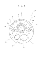
Fig. 7 is a plan illustrating the head assembly; -
Fig. 8 is a perspective view illustrating one preferred endoscope having a distal projection of a circumferential form; -
Fig. 9 is a perspective view illustrating still another preferred endoscope having an arcuate recess with fluid ports; -
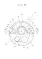
Fig. 10 is a plan illustrating the head assembly; -
Fig. 11 is a vertical section taken on line XI-XI inFigs. 9 and10 , illustrating the head assembly; -
Fig. 12 is a vertical section taken on line XII-XII inFigs. 9 and10 , illustrating the head assembly. - In
Fig. 1 , anelectronic endoscope system 11 includes anelectronic endoscope 12, aprocessing apparatus 13, alight source apparatus 14 and afluid supply source 15. Thefluid supply source 15 includes anair pump 15a for air supply, and awater reservoir 15b or a tank for washing. Theair pump 15a is a well-known device, is incorporated in thelight source apparatus 14, and supplies air. Thewater reservoir 15b is separate from thelight source apparatus 14, and stores water as washing fluid. Theendoscope 12 includes a section of anelongated tube 16, ahandle device 17, aconnector plug 18 and auniversal cable 19. Theelongated tube 16 is flexible and entered in a body of a patient. Thehandle device 17 is connected with a proximal end of theelongated tube 16. Theconnector plug 18 is plugged with theprocessing apparatus 13 and thelight source apparatus 14. Theuniversal cable 19 extends between thehandle device 17 and theconnector plug 18. Theconnector plug 18 is a composite type to which theprocessing apparatus 13, thelight source apparatus 14 and thefluid supply source 15 are coupled. - The
elongated tube 16 includes ahead assembly 16a, asteering device 16b, and aflexible tube 16c. ACCD 39 or image sensor ofFig. 2 is incorporated in thehead assembly 16a. Thesteering device 16b is disposed at a proximal end of thehead assembly 16a for steering. Theflexible tube 16c is disposed at a proximal end of thesteering device 16b. - The
processing apparatus 13 is connected with thelight source apparatus 14, and controls functions of theendoscope system 11. Theprocessing apparatus 13 supplies theendoscope 12 with power through a cable extending through theuniversal cable 19 and theelongated tube 16, and controls theCCD 39. Also, theprocessing apparatus 13 receives an image signal from theCCD 39 through the cable, and creates image data by image processing of the image signal. Amonitor display panel 20 is driven by means of the cable from theprocessing apparatus 13 to display an image according to the image data created by theprocessing apparatus 13. - In
Fig. 3 , afluid channel 21 is formed through theelongated tube 16 and thehandle device 17. An end nozzle device 22 (end nozzle) is incorporated in thehead assembly 16a, and has a nozzle opening with which thefluid channel 21 communicates. SeeFigs. 2-4 . Thefluid channel 21 extends through theuniversal cable 19 and is connected with thefluid supply source 15. - The
handle device 17 includes a proximal instrument opening 23, afluid supply button 24 andsteering wheels 25. The proximal instrument opening 23 receives entry of any of various medical instruments, such as an injection needle, electrocautery device of high frequency and the like. When thefluid supply button 24 is depressed for air supply, air generated by theair pump 15a is caused to flow to theend nozzle device 22. When thefluid supply button 24 is depressed for water supply, water as washing fluid in thewater reservoir 15b is caused to flow to theend nozzle device 22 by pressure of the air from theair pump 15a. Theend nozzle device 22 selectively ejects air or the washing fluid from thefluid channel 21. - When the
steering wheels 25 are rotated, control wires in theelongated tube 16 are moved back and forth to steer thesteering device 16b up or down or to the right or left. Thus, thehead assembly 16a is bent in a desired direction in a body cavity. - In
Figs. 2 ,3 and4 , theelongated tube 16 includes anend shell 26, ahead cap 27, animaging window area 28 or window unit,lighting window areas end nozzle device 22. Theend shell 26 includesmount holes elongated tube 16. Alens system 35 or objective lens is mounted in themount hole 26a as will be described later. Theend nozzle device 22 is mounted in themount hole 26b. Alight guide device 40 is mounted in each of the mount holes 26c. There is alink element 31 on a distal side in thesteering device 16b. A proximal end of theend shell 26 is connected to thelink element 31. - The
head cap 27 includes acap plate 27a and acap skirt 27b projecting from thecap plate 27a to extend on an outer surface of theend shell 26. Anouter tube 32 covers thesteering device 16b, extends toward theend shell 26. A distal end of theouter tube 32 is engaged with a proximal end of thecap skirt 27b, and attached thereto by use of adhesive agent or the like. Afirst surface 33 or end surface (tip surface) is located on thecap plate 27a, is flat and perpendicular to an axial direction of theelongated tube 16, and is positioned on a distal side of thehead assembly 16a. - The
cap plate 27a has throughopenings opening 27c is disposed in a portion near to the center of thehead assembly 16a as viewed in the axial direction, and is an aperture for theimaging window area 28. The throughopenings lighting window areas opening 27c. A throughhole 27f and the distal instrument opening 30 are formed in thefirst surface 33. The throughhole 27f is a mount hole for theend nozzle device 22. - The
imaging window area 28 is constituted by a window lens or objective lens as an element of thelens system 35 on the distal side, and also functions as a cover of glass. The window lens is in a circular shape, and has awindow surface 28a and aperipheral surface 28b around thewindow surface 28a. - A
lens barrel 36 includes thelens system 35 as optical system aligned with theimaging window area 28. Thelens barrel 36 is engaged with a proximal edge of theperipheral surface 28b of theimaging window area 28. A distal edge of theperipheral surface 28b of theimaging window area 28 is engaged with the throughopening 27c of thehead cap 27. Thelens barrel 36 is fitted in themount hole 26a of theend shell 26. A distal surface of thelens barrel 36 tightly contacts thecap plate 27a of thehead cap 27. - The
imaging window area 28 is disposed to set thewindow surface 28a at a predetermined height from thefirst surface 33. Anannular projection 37 is formed on thehead cap 27, is disposed between the edge of thewindow surface 28a and thefirst surface 33, and projects at a predetermined height from thefirst surface 33. Theannular projection 37 has an inner surface where the throughopening 27c is defined. Aninclined surface 38 is formed around theannular projection 37, and has a height gradually decreasing from thewindow surface 28a toward thefirst surface 33. - The
CCD 39 is disposed on a proximal side of thelens system 35. An example of theCCD 39 is an interline transfer CCD. An object image is focused on an imaging surface of theCCD 39 according to object light entered through thelens system 35. Note that an image sensor can be a CMOS image sensor in place of theCCD 39. - The
lighting window areas light source apparatus 14 toward an object of interest in a body cavity. A distal surface of thelighting window areas first surface 33 in the proximal direction. An exit end of thelight guide device 40 is opposed to a proximal surface of thelighting window areas light guide device 40 includes a bundle of plural optical fibers, a ring and a tube material. The ring is fitted on a distal end of the bundled optical fibers. The tube material is fitted on the periphery of the bundled optical fibers for covering. Thelight guide device 40 extends through theelongated tube 16, thehandle device 17, theuniversal cable 19 and theconnector plug 18, and guides light from thelight source apparatus 14 to thelighting window areas elongated tube 16. The distal instrument opening 30 is connected with the instrument channel, which communicates with the proximal instrument opening 23 in thehandle device 17. A distal end of any of various medical instruments entered in the proximal instrument opening 23 appears through thedistal instrument opening 30. - The
cap plate 27a hasrecesses distal projection 42 or fence wall. Therecesses lighting window areas first surface 33. Thedistal projection 42 projects from thefirst surface 33 in the distal direction. Therecesses first surface 33 toward thelighting window areas - The
end nozzle device 22 is one piece including anozzle spout 22a with a spout channel, and aflow conduit 22b or coupling sleeve. Theflow conduit 22b is coupled to a distal end of thefluid channel 21. Theflow conduit 22b and thefluid channel 21 are fitted in themount hole 26b of theend shell 26. Anozzle opening 43 is defined in thenozzle spout 22a. Thenozzle spout 22a is in a gradually curved shape from theflow conduit 22b toward its end, and appears externally through the throughhole 27f of thehead cap 27. A region of ejecting fluid from theend nozzle device 22 is so predetermined as to blow the fluid at least to theinclined surface 38, and preferably so predetermined as to blow the fluid to both theimaging window area 28 and theinclined surface 38. - The
distal projection 42 is disposed on a side in a path direction S from theend nozzle device 22, and projects in a distal direction. The fluid, when ejected from theend nozzle device 22, moves past theinclined surface 38 and theimaging window area 28, and then returns upon impingement with thedistal projection 42. Thehead cap 27 has anouter surface 27g. Thedistal projection 42 projects from thefirst surface 33, and is in an arcuate shape along an edge of thehead assembly 16a with theouter surface 27g. Also, thedistal projection 42 extends to positions near to thelighting window areas End portions distal projection 42 are formed to extend to therecesses - The operation of washing the
imaging window area 28 with the washing fluid from the end nozzle device 22 (end nozzle) in theendoscope 12 is described now as a process of the invention. The washing fluid such as air or water is ejected by theend nozzle device 22 and partially impinges on theinclined surface 38. The washing fluid on theinclined surface 38 is spread in the radial direction of theimaging window area 28 and moves up on theinclined surface 38. The washing fluid extends to the entirety of thewindow surface 28a of theimaging window area 28 to blow away body fluid or dirt from thewindow surface 28a. Also, air is blown to remove the water or liquid as washing fluid. - A component of washing fluid moved past the
imaging window area 28 and theinclined surface 38, among components ejected by theend nozzle device 22, impinges on and is returned by thedistal projection 42 to the center of thehead assembly 16a. As therecesses distal projection 42, the returned washing fluid enters therecesses recesses lighting window areas - Consequently, the
imaging window area 28 can be washed by the washing fluid from theend nozzle device 22. The washing fluid remains in therecesses lighting window areas recesses end nozzle device 22, thelighting window areas lighting window areas - As the
recesses distal projection 42 is introduced in therecesses distal projection 42 has the surface extending continuously with inner surfaces of therecesses - In
Fig. 5 , another preferred embodiment is illustrated, in which therecesses lighting window areas distal projection 42, inclusive of an annular region and a triangular extension region which are indicated with the phantom line. The extension region makes it easier to direct the returned washing fluid from thedistal projection 42 into therecesses end portions distal projection 42 are preferably disposed to extend to therecesses head assembly 16a. However, three or more lighting window areas can be formed in thehead assembly 16a. In combination with those, a recess can be formed in the head assembly with a profile containing the lighting window areas, and retreat in the proximal direction from thefirst surface 33, in the form similar to therecesses - A recess may be formed in a different manner from the
recesses lighting window areas Figs. 6 and7 , anotherpreferred head assembly 50 is illustrated. Arecess 51 is formed in thehead assembly 50 and disposed with a profile containing thelighting window areas distal projection 52 or fence wall projects from thehead assembly 50, and is disposed in the path direction S of theend nozzle device 22. Elements similar to those of the above embodiment are designated with identical reference numerals. - The
head assembly 50 has afirst surface 53 or end surface (tip surface). Therecess 51 retreats in the proximal direction from thefirst surface 53, is defined by two arcs between which thelighting window areas end nozzle device 22. Therecess 51 has a second surface 54 (recess surface) and aguide surface 55. Thesecond surface 54 is flat and retreats from thefirst surface 53 in the proximal direction. Theguide surface 55 is inclined from the periphery of theimaging window area 28 toward thesecond surface 54 in the proximal direction. Thefirst surface 53 is perpendicular to the axial direction of theelongated tube 16 in a similar manner to thefirst surface 33 of the first embodiment, and is positioned on a distal side in thehead assembly 50. Thelighting window areas second surface 54. Note that thesecond surface 54 can be preferably oriented in parallel with thefirst surface 53. - The
distal projection 52 projects in the distal direction from thesecond surface 54 and disposed along theouter surface 27g. First andsecond end portions distal projection 52 are formed to extend continuously with thefirst surface 53. Thus, washing fluid can be easily introduced in therecess 51 which is surrounded by thefirst surface 53 and thedistal projection 52. - This being so, the washing fluid, returned by the
distal projection 52 or moved past theimaging window area 28, comes to remain in therecess 51 after ejection from the end nozzle device, because therecess 51 is formed in thehead assembly 50. The washing fluid, because guided by theguide surface 55, remains on the window surface of thelighting window areas lighting window areas recess 51, to prevent deposition of body fluid or dirt thereon. - In the present embodiment, the
distal projection 52 projects from thesecond surface 54, and has the first andsecond end portions first surface 53. InFig. 8 , still another preferred embodiment is illustrated, in which thedistal projection 52 extends circumferentially at thehead assembly 50, and projects from thefirst surface 53 and thesecond surface 54 in a distal direction. In the above embodiment, the lighting window areas are two in thehead assembly 50. However, thehead assembly 50 may have three or more lighting window areas. For this structure, a single recess similar to therecess 51 in the above embodiment can be formed to retreat in the proximal direction from thefirst surface 53 and can be disposed with a profile containing the plural light window areas. - In the above embodiment, the washing fluid is caused to remain in the
recesses recess 51. InFigs. 9-12 , anotherpreferred head assembly 60 is illustrated. Arecess 61 is formed in thehead assembly 60 with a profile containing thelighting window areas outer surface 27g of thehead assembly 60. Adistal projection 62 or fence wall is formed on a side of the path direction of theend nozzle device 22, to cause the washing fluid to flow from therecess 61 to the outside. - The
head assembly 60 has afirst surface 63 or end surface. Therecess 61 retreats in the proximal direction from thefirst surface 63, and is disposed on a side of the path direction S of theend nozzle device 22. Therecess 61 has a second surface 64 (recess surface) and aguide surface 65. Thesecond surface 64 has a profile containing thelighting window areas first surface 63 in the proximal direction. Theguide surface 65 is inclined from the periphery of theimaging window area 28 toward thesecond surface 64 in the proximal direction. Thefirst surface 63 is perpendicular to the axial direction of theelongated tube 16 in a similar manner to thefirst surface 33 of the first embodiment, and is positioned on a distal side in thehead assembly 60. Note that thesecond surface 64 can be preferably oriented in parallel with thefirst surface 63. - The
distal projection 62 projects from thesecond surface 64 in the distal direction, extends along theouter surface 27g, and is arcuate to extend toward thelighting window areas distal projection 62 hasend portions first surface 63. First andsecond fluid ports first surface 63 and theend portions distal projection 62, for discharge of washing fluid between thesecond surface 64 and theouter surface 27g. -
Wall projections head assembly 60, project from thesecond surface 64 in the distal direction, and are disposed around thelighting window areas Inclined surfaces wall projections inclined surfaces lighting window areas second surface 64 in the proximal direction. Note that window surfaces of thelighting window areas wall projections Fig. 12 ) is predetermined lower than a height H2 of thefirst surface 63 with reference to thesecond surface 64. Thus, drainage of washing fluid on the surfaces of thelighting window areas - Thus, the washing fluid, returned by the
distal projection 62 or blown past theimaging window area 28, passes the first andsecond fluid ports end nozzle device 22, because of therecess 61 and positions of thelighting window areas first surface 63. Also, theguide surface 65 causes the washing fluid to flow on the window surface of thelighting window areas lighting window areas - In the present embodiment, the lighting window areas are two in the
head assembly 60. However, thehead assembly 60 may have three or more lighting window areas. For this structure, a single recess similar to therecess 61 in the embodiment can be formed to retreat in the proximal direction from thefirst surface 63, and can have a profile containing the plural light window areas to extend laterally to theouter surface 27g of thehead assembly 60 through the fluid ports. - In the above embodiment, the distal window surface of the
imaging window area 28 is flat. However, the window surface may be convex. A peripheral edge portion of the convex window surface may be flush with the distal end of theinclined surface 38, or may project from the distal end of theinclined surface 38 in the distal direction. Also, theimaging window area 28 may be disposed to keep thewindow surface 28a flush with the first surface without forming theannular projection 37 thereabout. Furthermore, theimaging window area 28 may project from the first surface with a certain height. An edge portion of theimaging window area 28 can be formed with inclination in a projecting form from the first surface without forming theannular projection 37. - Note that the
first surface head assembly 16a. Also, the first surface may be a slightly curved surface. - In the embodiments of the drawings except for
Fig. 8 , thedistal projection - In the above embodiments, the
recesses lighting window areas recesses - In the above embodiments, the
head cap 27 is originally separate from theend shell 26. However, the end shell can be one piece including the head cap formed therewith. - In the above embodiments, the endoscope includes the solid state imaging unit. However, the present invention can be used in an endoscope in which an optical image guide device is used for imaging. In the above embodiments, the washing fluid is water. However, various examples of washing fluid available in the field of the endoscope can be used, for example, alcohol, a mixture of water with fine particles for washing, and the like.
- Although the present invention has been fully described by way of the preferred embodiments thereof with reference to the accompanying drawings, various changes and modifications will be apparent to those having skill in this field. Therefore, unless otherwise these changes and modifications depart from the scope of the present invention, they should be construed as included therein.
Claims (12)
- An endoscope having a section of an elongated tube (16) for entry in a body cavity, characterized in comprising:a first surface (33, 53, 63), formed at a distal end of a head assembly (16a, 50, 60) included in said elongated tube, and disposed to extend crosswise to an axial direction of said elongated tube;a recess (41a, 41b, 51, 61) formed in said head assembly at a lower level than said first surface;at least one lighting window area (29a, 29b), disposed in said recess, for applying light to an object in said body cavity;an imaging window area (28), disposed in said first surface, for receiving light from said object;an end nozzle (22), disposed on said first surface, for washing said imaging window area by ejecting washing fluid thereto;a distal projection (42, 52, 62), formed on said head assembly at a higher level than said first surface, for receiving said washing fluid from said imaging window area.
- An endoscope as defined in claim 1, characterized in that a surface height of said imaging window area is larger than a height of said first surface.
- An endoscope as defined in claim 1, characterized in that said recess is annular and tapered, and disposed to surround said lighting window area.
- An endoscope as defined in claim 1, characterized in that said recess includes:an annular region formed in a cup shape, and disposed to surround said lighting window area;an extension region, disposed to extend from said lighting window area toward said distal projection, for introducing said washing fluid from said distal projection into said annular region.
- An endoscope as defined in claim 3 or 4, characterized in that said recess extends continuously with said distal projection.
- An endoscope as defined in claim 1, characterized in that said distal projection extends at least partially along an outer surface of said head assembly;
said recess is disposed between a periphery of said imaging window area and said distal projection, is in an arcuate shape, and has a second surface where said lighting window area is disposed. - An endoscope as defined in claim 6, characterized in further comprising an inclined guide surface disposed to extend continuously between said first and second surfaces.
- An endoscope as defined in claim 6, characterized in that said distal projection is in an arcuate shape, and has a center portion and two end portions.
- An endoscope as defined in claim 8, characterized in that said center portion has a large height in said distal projection, and said end portions are inclined with a height increasing from said first surface to said center portion.
- An endoscope as defined in claim 8, characterized in further comprising first and second fluid ports, disposed between said first surface and said end portions to extend from said recess to said outer surface of said head assembly, for directing said washing fluid.
- An endoscope as defined in claim 7, characterized in that said guide surface is disposed along a periphery of said imaging window area.
- An endoscope as defined in any one of claims 6-11, characterized in further comprising a wall projection, formed to project from said second surface, disposed to surround said lighting window area, and inclined with respect to said axial direction toward said second surface.
Applications Claiming Priority (1)
| Application Number | Priority Date | Filing Date | Title |
|---|---|---|---|
| JP2011042185A JP5331840B2 (en) | 2011-02-28 | 2011-02-28 | Endoscope |
Publications (2)
| Publication Number | Publication Date |
|---|---|
| EP2491848A1 true EP2491848A1 (en) | 2012-08-29 |
| EP2491848B1 EP2491848B1 (en) | 2014-01-15 |
Family
ID=45557955
Family Applications (1)
| Application Number | Title | Priority Date | Filing Date |
|---|---|---|---|
| EP12153364.0A Not-in-force EP2491848B1 (en) | 2011-02-28 | 2012-01-31 | Endoscope having end nozzle |
Country Status (3)
| Country | Link |
|---|---|
| EP (1) | EP2491848B1 (en) |
| JP (1) | JP5331840B2 (en) |
| CN (1) | CN102648841B (en) |
Cited By (12)
| Publication number | Priority date | Publication date | Assignee | Title |
|---|---|---|---|---|
| EP2859835A1 (en) * | 2013-10-08 | 2015-04-15 | Fujifilm Corporation | Endoscope |
| CN106714654A (en) * | 2015-05-13 | 2017-05-24 | 奥林巴斯株式会社 | Endoscope |
| EP3459425A1 (en) * | 2017-09-22 | 2019-03-27 | FUJIFILM Corporation | Endoscope |
| EP3461389A1 (en) * | 2017-09-28 | 2019-04-03 | FUJIFILM Corporation | Endoscope |
| WO2019164893A1 (en) | 2018-02-21 | 2019-08-29 | Medos International Sàrl | Surgical visualization systems and related methods |
| CN111493802A (en) * | 2020-04-24 | 2020-08-07 | 北京凡星光电医疗设备股份有限公司 | Endoscope lens flushing method and device and endoscope |
| EP3960063A1 (en) | 2020-09-01 | 2022-03-02 | Karl Storz SE & Co. KG | Optical instrument and method for producing an optical instrument |
| US11331090B2 (en) | 2015-09-04 | 2022-05-17 | Medos International Sarl | Surgical visualization systems and related methods |
| US11439380B2 (en) | 2015-09-04 | 2022-09-13 | Medos International Sarl | Surgical instrument connectors and related methods |
| US11559328B2 (en) | 2015-09-04 | 2023-01-24 | Medos International Sarl | Multi-shield spinal access system |
| US11672562B2 (en) | 2015-09-04 | 2023-06-13 | Medos International Sarl | Multi-shield spinal access system |
| US11744447B2 (en) | 2015-09-04 | 2023-09-05 | Medos International | Surgical visualization systems and related methods |
Families Citing this family (11)
| Publication number | Priority date | Publication date | Assignee | Title |
|---|---|---|---|---|
| CN103006173A (en) * | 2012-12-03 | 2013-04-03 | 河南科技大学 | Visible urethral sound for indwelling catheter |
| JP6050221B2 (en) * | 2013-12-20 | 2016-12-21 | 富士フイルム株式会社 | Endoscope |
| JP5942046B2 (en) * | 2014-05-07 | 2016-06-29 | オリンパス株式会社 | Endoscope |
| CN104049356B (en) * | 2014-06-09 | 2016-09-14 | 中国航天科工集团第三研究院第八三五八研究所 | Binocular solid endoscope body including planoconcave lens regards objective lens optical system |
| US12150636B2 (en) | 2015-09-04 | 2024-11-26 | Medos International Sárl | Surgical instrument connectors and related methods |
| EP3539445A1 (en) * | 2018-03-14 | 2019-09-18 | Ambu A/S | Method for manufacturing a tip housing |
| DE102018129904A1 (en) * | 2018-11-27 | 2020-05-28 | Olympus Winter & Ibe Gmbh | Resectoscope with an electrode instrument in the outer shaft |
| CN110613421A (en) * | 2019-09-23 | 2019-12-27 | 马玉龙 | Lens washing unit is used in operation |
| CN114727747B (en) * | 2019-11-29 | 2024-10-18 | 富士胶片株式会社 | Endoscope |
| CN114209265A (en) * | 2021-12-29 | 2022-03-22 | 上海澳华内镜股份有限公司 | Head end device of endoscope and endoscope |
| CN116869454A (en) * | 2023-08-23 | 2023-10-13 | 杭州微新医疗科技有限公司 | Mirror tube end, mirror tube and assembly method thereof, endoscope |
Citations (4)
| Publication number | Priority date | Publication date | Assignee | Title |
|---|---|---|---|---|
| JPS56113503U (en) * | 1980-01-31 | 1981-09-01 | ||
| JPS62192701U (en) * | 1986-05-28 | 1987-12-08 | ||
| JPH05207962A (en) * | 1992-01-31 | 1993-08-20 | Olympus Optical Co Ltd | Hard endoscope |
| JP2009279291A (en) * | 2008-05-26 | 2009-12-03 | Fujifilm Corp | Endoscope |
Family Cites Families (14)
| Publication number | Priority date | Publication date | Assignee | Title |
|---|---|---|---|---|
| JPS552408A (en) * | 1978-06-21 | 1980-01-09 | Olympus Optical Co | Internally examining mirror |
| JPH03116801U (en) * | 1990-03-16 | 1991-12-03 | ||
| JPH0422327A (en) * | 1990-05-18 | 1992-01-27 | Olympus Optical Co Ltd | Endoscope line control device |
| US5575756A (en) * | 1993-08-16 | 1996-11-19 | Olympus Optical Co., Ltd. | Endoscope apparatus |
| US5894369A (en) * | 1996-11-15 | 1999-04-13 | Fuji Photo Optical Co., Ltd. | Lens device with anti-fogging |
| JP3785908B2 (en) * | 2000-08-17 | 2006-06-14 | フジノン株式会社 | Endoscope observation window cleaning device |
| JP4391956B2 (en) * | 2005-03-15 | 2009-12-24 | オリンパスメディカルシステムズ株式会社 | Endoscope insertion part and endoscope |
| JP4754871B2 (en) * | 2005-05-11 | 2011-08-24 | オリンパスメディカルシステムズ株式会社 | End of the endoscope |
| JP4914638B2 (en) * | 2006-04-28 | 2012-04-11 | オリンパス株式会社 | Endoscope, endoscope apparatus, endoscope assembly method, endoscope apparatus assembly method |
| JP2007330529A (en) * | 2006-06-15 | 2007-12-27 | Olympus Medical Systems Corp | End of the endoscope |
| JP5078309B2 (en) * | 2006-10-04 | 2012-11-21 | オリンパスメディカルシステムズ株式会社 | Endoscope |
| EP2596743B1 (en) * | 2008-11-19 | 2014-12-31 | Fujifilm Corporation | Endoscope system and assist device |
| JP5554153B2 (en) * | 2010-06-11 | 2014-07-23 | 富士フイルム株式会社 | Endoscope |
| JP5261518B2 (en) * | 2011-03-01 | 2013-08-14 | 富士フイルム株式会社 | Endoscope |
-
2011
- 2011-02-28 JP JP2011042185A patent/JP5331840B2/en not_active Expired - Fee Related
-
2012
- 2012-01-31 EP EP12153364.0A patent/EP2491848B1/en not_active Not-in-force
- 2012-02-09 CN CN201210028842.9A patent/CN102648841B/en not_active Expired - Fee Related
Patent Citations (4)
| Publication number | Priority date | Publication date | Assignee | Title |
|---|---|---|---|---|
| JPS56113503U (en) * | 1980-01-31 | 1981-09-01 | ||
| JPS62192701U (en) * | 1986-05-28 | 1987-12-08 | ||
| JPH05207962A (en) * | 1992-01-31 | 1993-08-20 | Olympus Optical Co Ltd | Hard endoscope |
| JP2009279291A (en) * | 2008-05-26 | 2009-12-03 | Fujifilm Corp | Endoscope |
Cited By (27)
| Publication number | Priority date | Publication date | Assignee | Title |
|---|---|---|---|---|
| EP2859835A1 (en) * | 2013-10-08 | 2015-04-15 | Fujifilm Corporation | Endoscope |
| CN106714654A (en) * | 2015-05-13 | 2017-05-24 | 奥林巴斯株式会社 | Endoscope |
| EP3175771A4 (en) * | 2015-05-13 | 2018-09-05 | Olympus Corporation | Endoscope |
| CN106714654B (en) * | 2015-05-13 | 2018-11-13 | 奥林巴斯株式会社 | endoscope |
| US11672562B2 (en) | 2015-09-04 | 2023-06-13 | Medos International Sarl | Multi-shield spinal access system |
| US11744447B2 (en) | 2015-09-04 | 2023-09-05 | Medos International | Surgical visualization systems and related methods |
| US11883064B2 (en) | 2015-09-04 | 2024-01-30 | Medos International Sarl | Multi-shield spinal access system |
| US11806043B2 (en) | 2015-09-04 | 2023-11-07 | Medos International Sarl | Devices and methods for providing surgical access |
| US11801070B2 (en) | 2015-09-04 | 2023-10-31 | Medos International Sarl | Surgical access port stabilization |
| US11793546B2 (en) | 2015-09-04 | 2023-10-24 | Medos International Sarl | Surgical visualization systems and related methods |
| US11712264B2 (en) | 2015-09-04 | 2023-08-01 | Medos International Sarl | Multi-shield spinal access system |
| US11559328B2 (en) | 2015-09-04 | 2023-01-24 | Medos International Sarl | Multi-shield spinal access system |
| US11331090B2 (en) | 2015-09-04 | 2022-05-17 | Medos International Sarl | Surgical visualization systems and related methods |
| US11344190B2 (en) | 2015-09-04 | 2022-05-31 | Medos International Sarl | Surgical visualization systems and related methods |
| US11439380B2 (en) | 2015-09-04 | 2022-09-13 | Medos International Sarl | Surgical instrument connectors and related methods |
| US11363940B2 (en) | 2017-09-22 | 2022-06-21 | Fujifilm Corporation | Endoscope |
| EP3459425A1 (en) * | 2017-09-22 | 2019-03-27 | FUJIFILM Corporation | Endoscope |
| US11503983B2 (en) | 2017-09-28 | 2022-11-22 | Fujifilm Corporation | Endoscope |
| EP3461389A1 (en) * | 2017-09-28 | 2019-04-03 | FUJIFILM Corporation | Endoscope |
| US12178408B2 (en) | 2017-09-28 | 2024-12-31 | Fujifilm Corporation | Endoscope |
| EP3755198A4 (en) * | 2018-02-21 | 2021-10-27 | Medos International Sàrl | SURGICAL VISUALIZATION SYSTEMS AND ASSOCIATED PROCESSES |
| WO2019164893A1 (en) | 2018-02-21 | 2019-08-29 | Medos International Sàrl | Surgical visualization systems and related methods |
| CN111493802A (en) * | 2020-04-24 | 2020-08-07 | 北京凡星光电医疗设备股份有限公司 | Endoscope lens flushing method and device and endoscope |
| US20220061649A1 (en) * | 2020-09-01 | 2022-03-03 | Karl Storz Se & Co. Kg | Optical instrument and method for producing an optical device |
| DE102020122846A1 (en) | 2020-09-01 | 2022-03-03 | Karl Storz Se & Co. Kg | Optical instrument and method of making an optical instrument |
| EP3960063A1 (en) | 2020-09-01 | 2022-03-02 | Karl Storz SE & Co. KG | Optical instrument and method for producing an optical instrument |
| US12369786B2 (en) * | 2020-09-01 | 2025-07-29 | Karl Storz Se & Co. Kg | Optical instrument and method for producing an optical device |
Also Published As
| Publication number | Publication date |
|---|---|
| CN102648841A (en) | 2012-08-29 |
| JP2012179078A (en) | 2012-09-20 |
| EP2491848B1 (en) | 2014-01-15 |
| CN102648841B (en) | 2015-03-25 |
| JP5331840B2 (en) | 2013-10-30 |
Similar Documents
| Publication | Publication Date | Title |
|---|---|---|
| EP2491848B1 (en) | Endoscope having end nozzle | |
| EP2859835B1 (en) | Endoscope | |
| JP5261518B2 (en) | Endoscope | |
| EP2886037B1 (en) | Endoscope with nozzle | |
| US20140039260A1 (en) | Endoscope | |
| JP5779314B2 (en) | Endoscope device | |
| EP2532298B1 (en) | Fluid nozzle unit and endoscope | |
| JP5665650B2 (en) | Endoscope | |
| WO2017126196A1 (en) | Endoscope | |
| JP2010279533A (en) | Distal end structure for endoscope insertion section | |
| JP2004290457A (en) | Nozzle and endoscope for cleaning endoscope leading edge surface | |
| JP2015136515A (en) | endoscope | |
| JP2013220179A (en) | Endoscope | |
| JPS6041208Y2 (en) | Endoscope | |
| JPH09168504A (en) | Endoscope | |
| JP6165396B1 (en) | Endoscope | |
| JP2011212391A (en) | Endoscope apparatus and air/liquid feed nozzle |
Legal Events
| Date | Code | Title | Description |
|---|---|---|---|
| PUAI | Public reference made under article 153(3) epc to a published international application that has entered the european phase |
Free format text: ORIGINAL CODE: 0009012 |
|
| AK | Designated contracting states |
Kind code of ref document: A1 Designated state(s): AL AT BE BG CH CY CZ DE DK EE ES FI FR GB GR HR HU IE IS IT LI LT LU LV MC MK MT NL NO PL PT RO RS SE SI SK SM TR |
|
| AX | Request for extension of the european patent |
Extension state: BA ME |
|
| 17P | Request for examination filed |
Effective date: 20130205 |
|
| GRAP | Despatch of communication of intention to grant a patent |
Free format text: ORIGINAL CODE: EPIDOSNIGR1 |
|
| INTG | Intention to grant announced |
Effective date: 20130913 |
|
| GRAS | Grant fee paid |
Free format text: ORIGINAL CODE: EPIDOSNIGR3 |
|
| GRAA | (expected) grant |
Free format text: ORIGINAL CODE: 0009210 |
|
| AK | Designated contracting states |
Kind code of ref document: B1 Designated state(s): AL AT BE BG CH CY CZ DE DK EE ES FI FR GB GR HR HU IE IS IT LI LT LU LV MC MK MT NL NO PL PT RO RS SE SI SK SM TR |
|
| REG | Reference to a national code |
Ref country code: CH Ref legal event code: EP Ref country code: GB Ref legal event code: FG4D |
|
| REG | Reference to a national code |
Ref country code: AT Ref legal event code: REF Ref document number: 649408 Country of ref document: AT Kind code of ref document: T Effective date: 20140215 |
|
| REG | Reference to a national code |
Ref country code: IE Ref legal event code: FG4D |
|
| REG | Reference to a national code |
Ref country code: DE Ref legal event code: R096 Ref document number: 602012000793 Country of ref document: DE Effective date: 20140227 |
|
| REG | Reference to a national code |
Ref country code: NL Ref legal event code: VDEP Effective date: 20140115 |
|
| REG | Reference to a national code |
Ref country code: AT Ref legal event code: MK05 Ref document number: 649408 Country of ref document: AT Kind code of ref document: T Effective date: 20140115 |
|
| REG | Reference to a national code |
Ref country code: LT Ref legal event code: MG4D |
|
| PG25 | Lapsed in a contracting state [announced via postgrant information from national office to epo] |
Ref country code: NO Free format text: LAPSE BECAUSE OF FAILURE TO SUBMIT A TRANSLATION OF THE DESCRIPTION OR TO PAY THE FEE WITHIN THE PRESCRIBED TIME-LIMIT Effective date: 20140415 Ref country code: IS Free format text: LAPSE BECAUSE OF FAILURE TO SUBMIT A TRANSLATION OF THE DESCRIPTION OR TO PAY THE FEE WITHIN THE PRESCRIBED TIME-LIMIT Effective date: 20140515 Ref country code: LT Free format text: LAPSE BECAUSE OF FAILURE TO SUBMIT A TRANSLATION OF THE DESCRIPTION OR TO PAY THE FEE WITHIN THE PRESCRIBED TIME-LIMIT Effective date: 20140115 |
|
| PG25 | Lapsed in a contracting state [announced via postgrant information from national office to epo] |
Ref country code: PT Free format text: LAPSE BECAUSE OF FAILURE TO SUBMIT A TRANSLATION OF THE DESCRIPTION OR TO PAY THE FEE WITHIN THE PRESCRIBED TIME-LIMIT Effective date: 20140515 Ref country code: NL Free format text: LAPSE BECAUSE OF FAILURE TO SUBMIT A TRANSLATION OF THE DESCRIPTION OR TO PAY THE FEE WITHIN THE PRESCRIBED TIME-LIMIT Effective date: 20140115 Ref country code: SE Free format text: LAPSE BECAUSE OF FAILURE TO SUBMIT A TRANSLATION OF THE DESCRIPTION OR TO PAY THE FEE WITHIN THE PRESCRIBED TIME-LIMIT Effective date: 20140115 Ref country code: FI Free format text: LAPSE BECAUSE OF FAILURE TO SUBMIT A TRANSLATION OF THE DESCRIPTION OR TO PAY THE FEE WITHIN THE PRESCRIBED TIME-LIMIT Effective date: 20140115 Ref country code: AT Free format text: LAPSE BECAUSE OF FAILURE TO SUBMIT A TRANSLATION OF THE DESCRIPTION OR TO PAY THE FEE WITHIN THE PRESCRIBED TIME-LIMIT Effective date: 20140115 Ref country code: ES Free format text: LAPSE BECAUSE OF FAILURE TO SUBMIT A TRANSLATION OF THE DESCRIPTION OR TO PAY THE FEE WITHIN THE PRESCRIBED TIME-LIMIT Effective date: 20140115 Ref country code: CY Free format text: LAPSE BECAUSE OF FAILURE TO SUBMIT A TRANSLATION OF THE DESCRIPTION OR TO PAY THE FEE WITHIN THE PRESCRIBED TIME-LIMIT Effective date: 20140115 |
|
| PG25 | Lapsed in a contracting state [announced via postgrant information from national office to epo] |
Ref country code: BE Free format text: LAPSE BECAUSE OF FAILURE TO SUBMIT A TRANSLATION OF THE DESCRIPTION OR TO PAY THE FEE WITHIN THE PRESCRIBED TIME-LIMIT Effective date: 20140115 Ref country code: LV Free format text: LAPSE BECAUSE OF FAILURE TO SUBMIT A TRANSLATION OF THE DESCRIPTION OR TO PAY THE FEE WITHIN THE PRESCRIBED TIME-LIMIT Effective date: 20140115 Ref country code: RS Free format text: LAPSE BECAUSE OF FAILURE TO SUBMIT A TRANSLATION OF THE DESCRIPTION OR TO PAY THE FEE WITHIN THE PRESCRIBED TIME-LIMIT Effective date: 20140115 Ref country code: HR Free format text: LAPSE BECAUSE OF FAILURE TO SUBMIT A TRANSLATION OF THE DESCRIPTION OR TO PAY THE FEE WITHIN THE PRESCRIBED TIME-LIMIT Effective date: 20140115 |
|
| REG | Reference to a national code |
Ref country code: DE Ref legal event code: R097 Ref document number: 602012000793 Country of ref document: DE |
|
| PG25 | Lapsed in a contracting state [announced via postgrant information from national office to epo] |
Ref country code: CZ Free format text: LAPSE BECAUSE OF FAILURE TO SUBMIT A TRANSLATION OF THE DESCRIPTION OR TO PAY THE FEE WITHIN THE PRESCRIBED TIME-LIMIT Effective date: 20140115 Ref country code: DK Free format text: LAPSE BECAUSE OF FAILURE TO SUBMIT A TRANSLATION OF THE DESCRIPTION OR TO PAY THE FEE WITHIN THE PRESCRIBED TIME-LIMIT Effective date: 20140115 Ref country code: EE Free format text: LAPSE BECAUSE OF FAILURE TO SUBMIT A TRANSLATION OF THE DESCRIPTION OR TO PAY THE FEE WITHIN THE PRESCRIBED TIME-LIMIT Effective date: 20140115 Ref country code: MC Free format text: LAPSE BECAUSE OF FAILURE TO SUBMIT A TRANSLATION OF THE DESCRIPTION OR TO PAY THE FEE WITHIN THE PRESCRIBED TIME-LIMIT Effective date: 20140115 Ref country code: RO Free format text: LAPSE BECAUSE OF FAILURE TO SUBMIT A TRANSLATION OF THE DESCRIPTION OR TO PAY THE FEE WITHIN THE PRESCRIBED TIME-LIMIT Effective date: 20140115 |
|
| REG | Reference to a national code |
Ref country code: IE Ref legal event code: MM4A |
|
| PLBE | No opposition filed within time limit |
Free format text: ORIGINAL CODE: 0009261 |
|
| STAA | Information on the status of an ep patent application or granted ep patent |
Free format text: STATUS: NO OPPOSITION FILED WITHIN TIME LIMIT |
|
| PG25 | Lapsed in a contracting state [announced via postgrant information from national office to epo] |
Ref country code: PL Free format text: LAPSE BECAUSE OF FAILURE TO SUBMIT A TRANSLATION OF THE DESCRIPTION OR TO PAY THE FEE WITHIN THE PRESCRIBED TIME-LIMIT Effective date: 20140115 Ref country code: SK Free format text: LAPSE BECAUSE OF FAILURE TO SUBMIT A TRANSLATION OF THE DESCRIPTION OR TO PAY THE FEE WITHIN THE PRESCRIBED TIME-LIMIT Effective date: 20140115 |
|
| 26N | No opposition filed |
Effective date: 20141016 |
|
| PG25 | Lapsed in a contracting state [announced via postgrant information from national office to epo] |
Ref country code: IE Free format text: LAPSE BECAUSE OF NON-PAYMENT OF DUE FEES Effective date: 20140131 |
|
| REG | Reference to a national code |
Ref country code: DE Ref legal event code: R097 Ref document number: 602012000793 Country of ref document: DE Effective date: 20141016 |
|
| PG25 | Lapsed in a contracting state [announced via postgrant information from national office to epo] |
Ref country code: SI Free format text: LAPSE BECAUSE OF FAILURE TO SUBMIT A TRANSLATION OF THE DESCRIPTION OR TO PAY THE FEE WITHIN THE PRESCRIBED TIME-LIMIT Effective date: 20140115 |
|
| REG | Reference to a national code |
Ref country code: CH Ref legal event code: PL |
|
| PG25 | Lapsed in a contracting state [announced via postgrant information from national office to epo] |
Ref country code: CH Free format text: LAPSE BECAUSE OF NON-PAYMENT OF DUE FEES Effective date: 20150131 Ref country code: LI Free format text: LAPSE BECAUSE OF NON-PAYMENT OF DUE FEES Effective date: 20150131 |
|
| REG | Reference to a national code |
Ref country code: FR Ref legal event code: PLFP Year of fee payment: 5 |
|
| PG25 | Lapsed in a contracting state [announced via postgrant information from national office to epo] |
Ref country code: MT Free format text: LAPSE BECAUSE OF FAILURE TO SUBMIT A TRANSLATION OF THE DESCRIPTION OR TO PAY THE FEE WITHIN THE PRESCRIBED TIME-LIMIT Effective date: 20140115 |
|
| PG25 | Lapsed in a contracting state [announced via postgrant information from national office to epo] |
Ref country code: SM Free format text: LAPSE BECAUSE OF FAILURE TO SUBMIT A TRANSLATION OF THE DESCRIPTION OR TO PAY THE FEE WITHIN THE PRESCRIBED TIME-LIMIT Effective date: 20140115 |
|
| PG25 | Lapsed in a contracting state [announced via postgrant information from national office to epo] |
Ref country code: BG Free format text: LAPSE BECAUSE OF FAILURE TO SUBMIT A TRANSLATION OF THE DESCRIPTION OR TO PAY THE FEE WITHIN THE PRESCRIBED TIME-LIMIT Effective date: 20140115 Ref country code: IT Free format text: LAPSE BECAUSE OF FAILURE TO SUBMIT A TRANSLATION OF THE DESCRIPTION OR TO PAY THE FEE WITHIN THE PRESCRIBED TIME-LIMIT Effective date: 20140115 Ref country code: GR Free format text: LAPSE BECAUSE OF FAILURE TO SUBMIT A TRANSLATION OF THE DESCRIPTION OR TO PAY THE FEE WITHIN THE PRESCRIBED TIME-LIMIT Effective date: 20140416 |
|
| PG25 | Lapsed in a contracting state [announced via postgrant information from national office to epo] |
Ref country code: LU Free format text: LAPSE BECAUSE OF NON-PAYMENT OF DUE FEES Effective date: 20140131 Ref country code: TR Free format text: LAPSE BECAUSE OF FAILURE TO SUBMIT A TRANSLATION OF THE DESCRIPTION OR TO PAY THE FEE WITHIN THE PRESCRIBED TIME-LIMIT Effective date: 20140115 Ref country code: HU Free format text: LAPSE BECAUSE OF FAILURE TO SUBMIT A TRANSLATION OF THE DESCRIPTION OR TO PAY THE FEE WITHIN THE PRESCRIBED TIME-LIMIT; INVALID AB INITIO Effective date: 20120131 |
|
| REG | Reference to a national code |
Ref country code: FR Ref legal event code: PLFP Year of fee payment: 6 |
|
| REG | Reference to a national code |
Ref country code: DE Ref legal event code: R082 Ref document number: 602012000793 Country of ref document: DE Representative=s name: KLUNKER IP PATENTANWAELTE PARTG MBB, DE |
|
| REG | Reference to a national code |
Ref country code: FR Ref legal event code: PLFP Year of fee payment: 7 |
|
| PG25 | Lapsed in a contracting state [announced via postgrant information from national office to epo] |
Ref country code: MK Free format text: LAPSE BECAUSE OF FAILURE TO SUBMIT A TRANSLATION OF THE DESCRIPTION OR TO PAY THE FEE WITHIN THE PRESCRIBED TIME-LIMIT Effective date: 20140115 |
|
| PG25 | Lapsed in a contracting state [announced via postgrant information from national office to epo] |
Ref country code: AL Free format text: LAPSE BECAUSE OF FAILURE TO SUBMIT A TRANSLATION OF THE DESCRIPTION OR TO PAY THE FEE WITHIN THE PRESCRIBED TIME-LIMIT Effective date: 20140115 |
|
| PGFP | Annual fee paid to national office [announced via postgrant information from national office to epo] |
Ref country code: FR Payment date: 20201210 Year of fee payment: 10 |
|
| PGFP | Annual fee paid to national office [announced via postgrant information from national office to epo] |
Ref country code: GB Payment date: 20210120 Year of fee payment: 10 Ref country code: DE Payment date: 20210119 Year of fee payment: 10 |
|
| REG | Reference to a national code |
Ref country code: DE Ref legal event code: R119 Ref document number: 602012000793 Country of ref document: DE |
|
| GBPC | Gb: european patent ceased through non-payment of renewal fee |
Effective date: 20220131 |
|
| PG25 | Lapsed in a contracting state [announced via postgrant information from national office to epo] |
Ref country code: GB Free format text: LAPSE BECAUSE OF NON-PAYMENT OF DUE FEES Effective date: 20220131 Ref country code: DE Free format text: LAPSE BECAUSE OF NON-PAYMENT OF DUE FEES Effective date: 20220802 |
|
| PG25 | Lapsed in a contracting state [announced via postgrant information from national office to epo] |
Ref country code: FR Free format text: LAPSE BECAUSE OF NON-PAYMENT OF DUE FEES Effective date: 20220131 |