EP2490732B1 - A remotely activated piezoelectric pump for delivery of biological agents to the intervertebral disc and spine - Google Patents
A remotely activated piezoelectric pump for delivery of biological agents to the intervertebral disc and spine Download PDFInfo
- Publication number
- EP2490732B1 EP2490732B1 EP10825505.0A EP10825505A EP2490732B1 EP 2490732 B1 EP2490732 B1 EP 2490732B1 EP 10825505 A EP10825505 A EP 10825505A EP 2490732 B1 EP2490732 B1 EP 2490732B1
- Authority
- EP
- European Patent Office
- Prior art keywords
- pump
- spine
- coupled
- spinal
- control system
- Prior art date
- Legal status (The legal status is an assumption and is not a legal conclusion. Google has not performed a legal analysis and makes no representation as to the accuracy of the status listed.)
- Not-in-force
Links
Images



Classifications
-
- A—HUMAN NECESSITIES
- A61—MEDICAL OR VETERINARY SCIENCE; HYGIENE
- A61M—DEVICES FOR INTRODUCING MEDIA INTO, OR ONTO, THE BODY; DEVICES FOR TRANSDUCING BODY MEDIA OR FOR TAKING MEDIA FROM THE BODY; DEVICES FOR PRODUCING OR ENDING SLEEP OR STUPOR
- A61M37/00—Other apparatus for introducing media into the body; Percutany, i.e. introducing medicines into the body by diffusion through the skin
-
- A—HUMAN NECESSITIES
- A61—MEDICAL OR VETERINARY SCIENCE; HYGIENE
- A61F—FILTERS IMPLANTABLE INTO BLOOD VESSELS; PROSTHESES; DEVICES PROVIDING PATENCY TO, OR PREVENTING COLLAPSING OF, TUBULAR STRUCTURES OF THE BODY, e.g. STENTS; ORTHOPAEDIC, NURSING OR CONTRACEPTIVE DEVICES; FOMENTATION; TREATMENT OR PROTECTION OF EYES OR EARS; BANDAGES, DRESSINGS OR ABSORBENT PADS; FIRST-AID KITS
- A61F2/00—Filters implantable into blood vessels; Prostheses, i.e. artificial substitutes or replacements for parts of the body; Appliances for connecting them with the body; Devices providing patency to, or preventing collapsing of, tubular structures of the body, e.g. stents
- A61F2/02—Prostheses implantable into the body
- A61F2/30—Joints
- A61F2/44—Joints for the spine, e.g. vertebrae, spinal discs
- A61F2/4455—Joints for the spine, e.g. vertebrae, spinal discs for the fusion of spinal bodies, e.g. intervertebral fusion of adjacent spinal bodies, e.g. fusion cages
- A61F2/4465—Joints for the spine, e.g. vertebrae, spinal discs for the fusion of spinal bodies, e.g. intervertebral fusion of adjacent spinal bodies, e.g. fusion cages having a circular or kidney shaped cross-section substantially perpendicular to the axis of the spine
-
- A—HUMAN NECESSITIES
- A61—MEDICAL OR VETERINARY SCIENCE; HYGIENE
- A61M—DEVICES FOR INTRODUCING MEDIA INTO, OR ONTO, THE BODY; DEVICES FOR TRANSDUCING BODY MEDIA OR FOR TAKING MEDIA FROM THE BODY; DEVICES FOR PRODUCING OR ENDING SLEEP OR STUPOR
- A61M5/00—Devices for bringing media into the body in a subcutaneous, intra-vascular or intramuscular way; Accessories therefor, e.g. filling or cleaning devices, arm-rests
- A61M5/14—Infusion devices, e.g. infusing by gravity; Blood infusion; Accessories therefor
- A61M5/142—Pressure infusion, e.g. using pumps
- A61M5/14244—Pressure infusion, e.g. using pumps adapted to be carried by the patient, e.g. portable on the body
- A61M5/14276—Pressure infusion, e.g. using pumps adapted to be carried by the patient, e.g. portable on the body specially adapted for implantation
-
- A—HUMAN NECESSITIES
- A61—MEDICAL OR VETERINARY SCIENCE; HYGIENE
- A61M—DEVICES FOR INTRODUCING MEDIA INTO, OR ONTO, THE BODY; DEVICES FOR TRANSDUCING BODY MEDIA OR FOR TAKING MEDIA FROM THE BODY; DEVICES FOR PRODUCING OR ENDING SLEEP OR STUPOR
- A61M5/00—Devices for bringing media into the body in a subcutaneous, intra-vascular or intramuscular way; Accessories therefor, e.g. filling or cleaning devices, arm-rests
- A61M5/14—Infusion devices, e.g. infusing by gravity; Blood infusion; Accessories therefor
- A61M5/142—Pressure infusion, e.g. using pumps
- A61M5/145—Pressure infusion, e.g. using pumps using pressurised reservoirs, e.g. pressurised by means of pistons
- A61M5/1452—Pressure infusion, e.g. using pumps using pressurised reservoirs, e.g. pressurised by means of pistons pressurised by means of pistons
-
- A—HUMAN NECESSITIES
- A61—MEDICAL OR VETERINARY SCIENCE; HYGIENE
- A61F—FILTERS IMPLANTABLE INTO BLOOD VESSELS; PROSTHESES; DEVICES PROVIDING PATENCY TO, OR PREVENTING COLLAPSING OF, TUBULAR STRUCTURES OF THE BODY, e.g. STENTS; ORTHOPAEDIC, NURSING OR CONTRACEPTIVE DEVICES; FOMENTATION; TREATMENT OR PROTECTION OF EYES OR EARS; BANDAGES, DRESSINGS OR ABSORBENT PADS; FIRST-AID KITS
- A61F2/00—Filters implantable into blood vessels; Prostheses, i.e. artificial substitutes or replacements for parts of the body; Appliances for connecting them with the body; Devices providing patency to, or preventing collapsing of, tubular structures of the body, e.g. stents
- A61F2/02—Prostheses implantable into the body
- A61F2/28—Bones
- A61F2002/2817—Bone stimulation by chemical reactions or by osteogenic or biological products for enhancing ossification, e.g. by bone morphogenetic or morphogenic proteins [BMP] or by transforming growth factors [TGF]
-
- A—HUMAN NECESSITIES
- A61—MEDICAL OR VETERINARY SCIENCE; HYGIENE
- A61F—FILTERS IMPLANTABLE INTO BLOOD VESSELS; PROSTHESES; DEVICES PROVIDING PATENCY TO, OR PREVENTING COLLAPSING OF, TUBULAR STRUCTURES OF THE BODY, e.g. STENTS; ORTHOPAEDIC, NURSING OR CONTRACEPTIVE DEVICES; FOMENTATION; TREATMENT OR PROTECTION OF EYES OR EARS; BANDAGES, DRESSINGS OR ABSORBENT PADS; FIRST-AID KITS
- A61F2/00—Filters implantable into blood vessels; Prostheses, i.e. artificial substitutes or replacements for parts of the body; Appliances for connecting them with the body; Devices providing patency to, or preventing collapsing of, tubular structures of the body, e.g. stents
- A61F2/02—Prostheses implantable into the body
- A61F2/30—Joints
- A61F2002/30001—Additional features of subject-matter classified in A61F2/28, A61F2/30 and subgroups thereof
- A61F2002/30316—The prosthesis having different structural features at different locations within the same prosthesis; Connections between prosthetic parts; Special structural features of bone or joint prostheses not otherwise provided for
- A61F2002/30535—Special structural features of bone or joint prostheses not otherwise provided for
- A61F2002/30593—Special structural features of bone or joint prostheses not otherwise provided for hollow
-
- A—HUMAN NECESSITIES
- A61—MEDICAL OR VETERINARY SCIENCE; HYGIENE
- A61F—FILTERS IMPLANTABLE INTO BLOOD VESSELS; PROSTHESES; DEVICES PROVIDING PATENCY TO, OR PREVENTING COLLAPSING OF, TUBULAR STRUCTURES OF THE BODY, e.g. STENTS; ORTHOPAEDIC, NURSING OR CONTRACEPTIVE DEVICES; FOMENTATION; TREATMENT OR PROTECTION OF EYES OR EARS; BANDAGES, DRESSINGS OR ABSORBENT PADS; FIRST-AID KITS
- A61F2/00—Filters implantable into blood vessels; Prostheses, i.e. artificial substitutes or replacements for parts of the body; Appliances for connecting them with the body; Devices providing patency to, or preventing collapsing of, tubular structures of the body, e.g. stents
- A61F2/02—Prostheses implantable into the body
- A61F2/30—Joints
- A61F2002/30001—Additional features of subject-matter classified in A61F2/28, A61F2/30 and subgroups thereof
- A61F2002/30667—Features concerning an interaction with the environment or a particular use of the prosthesis
- A61F2002/30668—Means for transferring electromagnetic energy to implants
- A61F2002/3067—Means for transferring electromagnetic energy to implants for data transfer
-
- A—HUMAN NECESSITIES
- A61—MEDICAL OR VETERINARY SCIENCE; HYGIENE
- A61F—FILTERS IMPLANTABLE INTO BLOOD VESSELS; PROSTHESES; DEVICES PROVIDING PATENCY TO, OR PREVENTING COLLAPSING OF, TUBULAR STRUCTURES OF THE BODY, e.g. STENTS; ORTHOPAEDIC, NURSING OR CONTRACEPTIVE DEVICES; FOMENTATION; TREATMENT OR PROTECTION OF EYES OR EARS; BANDAGES, DRESSINGS OR ABSORBENT PADS; FIRST-AID KITS
- A61F2/00—Filters implantable into blood vessels; Prostheses, i.e. artificial substitutes or replacements for parts of the body; Appliances for connecting them with the body; Devices providing patency to, or preventing collapsing of, tubular structures of the body, e.g. stents
- A61F2/02—Prostheses implantable into the body
- A61F2/30—Joints
- A61F2002/30001—Additional features of subject-matter classified in A61F2/28, A61F2/30 and subgroups thereof
- A61F2002/30667—Features concerning an interaction with the environment or a particular use of the prosthesis
- A61F2002/30677—Means for introducing or releasing pharmaceutical products, e.g. antibiotics, into the body
-
- A—HUMAN NECESSITIES
- A61—MEDICAL OR VETERINARY SCIENCE; HYGIENE
- A61F—FILTERS IMPLANTABLE INTO BLOOD VESSELS; PROSTHESES; DEVICES PROVIDING PATENCY TO, OR PREVENTING COLLAPSING OF, TUBULAR STRUCTURES OF THE BODY, e.g. STENTS; ORTHOPAEDIC, NURSING OR CONTRACEPTIVE DEVICES; FOMENTATION; TREATMENT OR PROTECTION OF EYES OR EARS; BANDAGES, DRESSINGS OR ABSORBENT PADS; FIRST-AID KITS
- A61F2/00—Filters implantable into blood vessels; Prostheses, i.e. artificial substitutes or replacements for parts of the body; Appliances for connecting them with the body; Devices providing patency to, or preventing collapsing of, tubular structures of the body, e.g. stents
- A61F2/02—Prostheses implantable into the body
- A61F2/30—Joints
- A61F2/30767—Special external or bone-contacting surface, e.g. coating for improving bone ingrowth
- A61F2/30771—Special external or bone-contacting surface, e.g. coating for improving bone ingrowth applied in original prostheses, e.g. holes or grooves
- A61F2002/30772—Apertures or holes, e.g. of circular cross section
- A61F2002/30784—Plurality of holes
- A61F2002/30785—Plurality of holes parallel
-
- A—HUMAN NECESSITIES
- A61—MEDICAL OR VETERINARY SCIENCE; HYGIENE
- A61F—FILTERS IMPLANTABLE INTO BLOOD VESSELS; PROSTHESES; DEVICES PROVIDING PATENCY TO, OR PREVENTING COLLAPSING OF, TUBULAR STRUCTURES OF THE BODY, e.g. STENTS; ORTHOPAEDIC, NURSING OR CONTRACEPTIVE DEVICES; FOMENTATION; TREATMENT OR PROTECTION OF EYES OR EARS; BANDAGES, DRESSINGS OR ABSORBENT PADS; FIRST-AID KITS
- A61F2/00—Filters implantable into blood vessels; Prostheses, i.e. artificial substitutes or replacements for parts of the body; Appliances for connecting them with the body; Devices providing patency to, or preventing collapsing of, tubular structures of the body, e.g. stents
- A61F2/02—Prostheses implantable into the body
- A61F2/30—Joints
- A61F2/30767—Special external or bone-contacting surface, e.g. coating for improving bone ingrowth
- A61F2/30771—Special external or bone-contacting surface, e.g. coating for improving bone ingrowth applied in original prostheses, e.g. holes or grooves
- A61F2002/30772—Apertures or holes, e.g. of circular cross section
- A61F2002/30784—Plurality of holes
- A61F2002/30787—Plurality of holes inclined obliquely with respect to each other
-
- A—HUMAN NECESSITIES
- A61—MEDICAL OR VETERINARY SCIENCE; HYGIENE
- A61F—FILTERS IMPLANTABLE INTO BLOOD VESSELS; PROSTHESES; DEVICES PROVIDING PATENCY TO, OR PREVENTING COLLAPSING OF, TUBULAR STRUCTURES OF THE BODY, e.g. STENTS; ORTHOPAEDIC, NURSING OR CONTRACEPTIVE DEVICES; FOMENTATION; TREATMENT OR PROTECTION OF EYES OR EARS; BANDAGES, DRESSINGS OR ABSORBENT PADS; FIRST-AID KITS
- A61F2/00—Filters implantable into blood vessels; Prostheses, i.e. artificial substitutes or replacements for parts of the body; Appliances for connecting them with the body; Devices providing patency to, or preventing collapsing of, tubular structures of the body, e.g. stents
- A61F2/02—Prostheses implantable into the body
- A61F2/30—Joints
- A61F2/30767—Special external or bone-contacting surface, e.g. coating for improving bone ingrowth
- A61F2/30771—Special external or bone-contacting surface, e.g. coating for improving bone ingrowth applied in original prostheses, e.g. holes or grooves
- A61F2002/30841—Sharp anchoring protrusions for impaction into the bone, e.g. sharp pins, spikes
-
- A—HUMAN NECESSITIES
- A61—MEDICAL OR VETERINARY SCIENCE; HYGIENE
- A61F—FILTERS IMPLANTABLE INTO BLOOD VESSELS; PROSTHESES; DEVICES PROVIDING PATENCY TO, OR PREVENTING COLLAPSING OF, TUBULAR STRUCTURES OF THE BODY, e.g. STENTS; ORTHOPAEDIC, NURSING OR CONTRACEPTIVE DEVICES; FOMENTATION; TREATMENT OR PROTECTION OF EYES OR EARS; BANDAGES, DRESSINGS OR ABSORBENT PADS; FIRST-AID KITS
- A61F2/00—Filters implantable into blood vessels; Prostheses, i.e. artificial substitutes or replacements for parts of the body; Appliances for connecting them with the body; Devices providing patency to, or preventing collapsing of, tubular structures of the body, e.g. stents
- A61F2/02—Prostheses implantable into the body
- A61F2/30—Joints
- A61F2/30767—Special external or bone-contacting surface, e.g. coating for improving bone ingrowth
- A61F2002/3092—Special external or bone-contacting surface, e.g. coating for improving bone ingrowth having an open-celled or open-pored structure
-
- A—HUMAN NECESSITIES
- A61—MEDICAL OR VETERINARY SCIENCE; HYGIENE
- A61F—FILTERS IMPLANTABLE INTO BLOOD VESSELS; PROSTHESES; DEVICES PROVIDING PATENCY TO, OR PREVENTING COLLAPSING OF, TUBULAR STRUCTURES OF THE BODY, e.g. STENTS; ORTHOPAEDIC, NURSING OR CONTRACEPTIVE DEVICES; FOMENTATION; TREATMENT OR PROTECTION OF EYES OR EARS; BANDAGES, DRESSINGS OR ABSORBENT PADS; FIRST-AID KITS
- A61F2310/00—Prostheses classified in A61F2/28 or A61F2/30 - A61F2/44 being constructed from or coated with a particular material
- A61F2310/00005—The prosthesis being constructed from a particular material
- A61F2310/00011—Metals or alloys
- A61F2310/00023—Titanium or titanium-based alloys, e.g. Ti-Ni alloys
-
- A—HUMAN NECESSITIES
- A61—MEDICAL OR VETERINARY SCIENCE; HYGIENE
- A61M—DEVICES FOR INTRODUCING MEDIA INTO, OR ONTO, THE BODY; DEVICES FOR TRANSDUCING BODY MEDIA OR FOR TAKING MEDIA FROM THE BODY; DEVICES FOR PRODUCING OR ENDING SLEEP OR STUPOR
- A61M2205/00—General characteristics of the apparatus
- A61M2205/02—General characteristics of the apparatus characterised by a particular materials
- A61M2205/0272—Electro-active or magneto-active materials
- A61M2205/0294—Piezoelectric materials
-
- A—HUMAN NECESSITIES
- A61—MEDICAL OR VETERINARY SCIENCE; HYGIENE
- A61M—DEVICES FOR INTRODUCING MEDIA INTO, OR ONTO, THE BODY; DEVICES FOR TRANSDUCING BODY MEDIA OR FOR TAKING MEDIA FROM THE BODY; DEVICES FOR PRODUCING OR ENDING SLEEP OR STUPOR
- A61M2205/00—General characteristics of the apparatus
- A61M2205/82—Internal energy supply devices
- A61M2205/8237—Charging means
- A61M2205/8243—Charging means by induction
-
- A—HUMAN NECESSITIES
- A61—MEDICAL OR VETERINARY SCIENCE; HYGIENE
- A61M—DEVICES FOR INTRODUCING MEDIA INTO, OR ONTO, THE BODY; DEVICES FOR TRANSDUCING BODY MEDIA OR FOR TAKING MEDIA FROM THE BODY; DEVICES FOR PRODUCING OR ENDING SLEEP OR STUPOR
- A61M2210/00—Anatomical parts of the body
- A61M2210/10—Trunk
- A61M2210/1003—Spinal column
Definitions
- the invention relates to the field of implantable drug delivery systems, specifically to a remotely activated piezoelectric pump for the controlled delivery of biological agents to the disc space and spine.
- RhBMP-2 recombinant human bone morphogenetic protein-2
- RhBMP-2 will eliminate the need for bone transplantation from the pelvis. It may also more reliably and more quickly produce fusion of spinal vertebrae. It may even reduce the need for the implantation of spinal rods and screws.
- Back pain is one of the 15 most commonly treated medical conditions in the United States today and is second only to the common cold as the most common reason for physician visits. Back pain not only has a profound effect on patients, it has an exceedingly high societal cost. Back pain is the second most common cause of lost productive time of the pain disorders and results in the largest amount of total lost time. It has been stated that of all medical conditions, back pain results in the most lost productivity. It is estimated that the direct and indirect costs associated with the disorder are approximately 50 billion dollars per year in the United States alone. Although back pain is multifactorial, degenerative disc disease is often involved in the pathogenesis and subsequent propagation of lower back pain. The disc space is composed of disc and surrounding annulus fibrosus. As the disc degenerates hypertrophy is increased in order to support the body weight, eventually leading to back pain.
- Iliad crest autografts have associated morbidities related to the harvesting, including pain at the donor site. Moreover, the consistency of the bone harvested is dependent on patient's intrinsic bone quality and the surgeon's ability to harvest a significant amount of bone needed for a bony fusion.
- the need for a bone graft substitute that can consistently lead to bony fusions without the need for iliac crest autografts has resulted in the production of bone graft substitutes, such as demineralized bone matrix (DBM).
- DBM is a bone graft extender, made of allograft, which has the capacity to be osteoconductive, that is, serve as a bridge between two bone chips to facilitate a fusion. DBM, however, is not capable of forming new bone (osteoinductive).
- BMP-2 human bone morphogenetic protein-2
- INFUSE absorbable collagen sponge
- the mean residence time of BMP-2 after implantation has been measured in a rat femoral only model implantation model to be 7.8 days.
- the maximum level of BMP-2 detected in the circulation was 0.1% of the implanted dose after six hours.
- the mean residence time ranged from 3.6 to 4.6 days (McKay-p. 72).
- BMP-2 is estimated to be present at the implant site for 3-4 weeks, and is cleared from the blood by the liver and excreted via the urine. Histology from animal models suggests that the ACS is reabsorbed in 4-12 weeks.
- BMP-2 is only FDA approved for anterior lumbar fusions, it has already been used in many different types of spinal fusion surgeries, including posterolateral fusions, and anterior cervical fusions.
- the posterolateral fusions appear to be effective with BMP-2 (although there was concern that it may actually work too well, and cause spinal stenosis).
- the anterior cervical fusions were effective from the standpoint of cervical fusions, but often induced tracheal-esophageal swelling, leading to emergency intubations in some patients.
- BMP-2 for human bones is used at the concentration of 1.5 mag BMP-2 per 1 cc of solution.
- the cage is filled with 4 cc of collagen sponge, saturated with 4 cc of the 1.5 mg/cc BMP-2 solution.
- WO 2008/030832 discloses controlled release devices for fusion of osteal structures.
- WO 2005/032658 discloses a user interface for external charger for implantable medical device.
- WO 2009/092067 discloses a valveless impedance pump drug delivery system.
- US 2008/025987 refers to the release of BMP, bioactive agents and/or cells via a pump into a carrier matrix in a patient.
- What is needed is apparatus that provides continuous infusion of various growth factors into the disc space to preserve it, instead of removing and fusing it in order to alleviate the thousands of patients currently suffering from chronic low back pain.
- the invention described herein is directed specifically to the infusion of biological agents to the spine and disc space.
- the concept of delivery of biological agents is similar, different devices will be tailor made for delivery depending on location of placement (i.e. posterior versus anterior spinal column, or intervertebral disc).
- the biological agent to be used will be different, depending on the disease process to be treated. For instance, in the degenerating disc, it may be used for the direct infusion of biological growth factors to preserve degenerating discs.
- the interbody disc In the case where the interbody disc is removed during surgery, it may be placed into an interbody graft to slowly release bMP-2 placed for an interbody fusion. It may also be placed for posterolateral fusion.
- the present disclosure also describes an apparatus that allows an architecture for constructing a remotely activated piezoelectric pump for delivery of biological agents to the intervertebral disc and spine.
- the current device provides the physician with a parametric bone development model relative to a parametric delivery of dose, duration and structural adhesion of the bone formation as a measure of BMP-2 infusion as characterized by differentiation and growth of chondrocytes from the proliferation zone to the hypertrophying one.
- These two cellular processes are controlled by a complex signaling regulatory loop between different biochemical signals, whose production depends on the current cell density, constituting a coupled cell-chemical system.
- the current invention employs a mathematical model that enables the regulation as well as attenuation of the process by extending and generalizing the model to enhance and optimize the delivery of BMP-2 in a regulated manner.
- a reaction-diffusion regulatory loop between the medicating agents and the disc space is measured by the use of a predictable algorithm.
- the model represented as a set of equations is further solved within a finite element framework, getting am estimation of the spatial distribution, growth of the bone structure and formation. The results obtained are assumed to be qualitatively similar to the actual physiological ones and quantitatively close to some available experimental data noted by clinical studies.
- An object of the current invention is to provide a patient with a metronomic infusion of BMP-2 over the course of a fusion.
- the piezoelectric pump currently proposed will be able to deliver biological agents such as BMP-2 in a controlled fashion, allowing a more sustained infusion of BMP-2 of up to 3 months.
- Fusions will be divided into interbody anterior fusions and posterolateral fusions.
- anterior interbody fusions a bony femoral allograft, PEEK cage, titanium cage, or titanium expandable cage is used in ALIFs or in anterior spine surgery.
- posterolateral fusions the pump will be coupled to a irrigating catheter so that it can be placed in the posterolateral gutter to deliver BMP-2 over the bony fusion.
- Another object of the current invention is to store the BMP-2 in an implant reservoir, which may be accessed externally and refilled multiple times with the use of a syringe.
- the BMP-2 content in the reservoir is then delivered into the spine disc via a small pump.
- a micro piezoelectric actuator such as a squiggle motor, which is a type of extremely small ultrasonic piezo linear motor suitable for use in highly miniaturized devices.
- a micro piezoelectric actuator such as a squiggle motor
- These simple, robust piezo motors can be scaled down to much smaller sizes than electromagnetic motors without significant loss of power efficiency, which makes them ideal for this implant application.
- the piezoelectric pump is protected in a PEEK or titanium housing that is capable of withstanding impacts and changes in pressure within the spinal column due to body motion.
- the titanium housing is designed to fit the specific indication and anatomy of the spine in which it will be implanted.
- the invention comprises a pump whose actuation can be energized and controlled from an inductive power source.
- the pump and its electronics will remain passive until power is received from the control units via inductive coils.
- the control unit communicates to the implant over the inductive link for on/off control of the pump and to adjust the rate of infusion of the BMP-2.
- the pump releases BMP-2 into a delivery catheter at the commanded rate, allowing the control unit to adjust the rate of infusion of BMP-2.
- the inductive power energizes a plurality of mechanosensors whose values can be queried via the said inductive communication link.
- Another object of the invention is to direct intradiscal delivery of BMP-2 via a delivery catheter to irrigation channels in the interbody cage so that it is not just absorbed in a passive manner, but is directed and irrigating the specific fusion site.
- the irrigation channels are shaped and configured so that BMP-2 is delivered equally throughout the interbody cage.
- two mechanosensors are placed, one within the pumping unit and a second on the adjacent vertebra.
- the mechanosensors provide information on how the fusion is progressing on a mechanical basis by physiological monitoring of relative motion between the two vertebras above and below the fusion disc.
- the data on the progress of the fusion between the two spinal bone segments which is sent via the inductive communication link, helps a physician monitor the progress of the fusion and ascertain whether an optimal fusion has taken place. When the two bone segments are totally fused, the difference in acceleration of the two vertebras should be become negligible.
- It is yet another object of the invention is to provide the concept of restoration.
- the current invention provides a constant infusion of biological agents into the disc space to preserve its integrity and to repair a disc that is damaged from degenerative disease.
- the infusion is performed by an implanted pump which is capable of being refilled subcutaneously via an external needle, allowing for varying concentrations and types of growth factors to be infused directly into the disc space.
- Absorbable Collagen Sponge refers to the sponge in the center of the carrier matrix designed to eventually be broken down and absorbed by the body as bone grows through it. It is made up of collagen which is the main protein of connective tissue in animals and the most abundant protein in mammals. Collagen has great tensile strength, and is the main component of fascia, cartilage, ligaments, tendons, bone and skin.
- anterior lumbar fusion refers to an operation done on the front (the anterior region) of the lower spine. Fusion surgery helps two or more bones grow together into one solid bone. Fusion cages are new devices, essentially hollow screws filled with bone graft, that help the bones of the spine heal together firmly. Surgeons use this procedure when patients have symptoms from disc degeneration, disc herniation, or spinal instability.
- Anterior Lumbar Interbody Fusion Device refers to the allograft spacers similar to those produced by Synthes North America to meet. the specific demands of spinal applications.
- BMP But Morphogenetic Proteins
- Carrier Matrix refers to biomaterials for the orthopedic implant market which, when placed in a bone defect, provide scaffolding through and around which the patient's new bone will grow, gradually replacing the carrier matrix as the target site heals.
- Controlled Administration System refers to a system which provides localized delivery either continuously or intermittently.
- Inductive Power refers to powering electronics using electromagnetic induction.
- a supplying induction coil sends energy through inductive coupling to a receiving inductive coil in an electrical device, which utilizes the energy. Because there is a small gap between the two coils, inductive charging is one kind of short-distance wireless energy transfer.
- Interbody spinal cages are rigid (i.e. titanium, PEEK, or allograft) spacers, usually cylindrical, that are placed in the disc space.
- the cages are porous and allow the bone graft to grow from the vertebral body through the cage and into the next vertebral body.
- “Localized Delivery” as used herein refers to non-systemic delivery to a site within approximately 10 cm of the site where bone growth is desired.
- Ostogenic refers to the ability to generate or stimulate bone growth.
- Ostoconduction refers to the ability to stimulate the attachment, migration, and distribution of vascular and osteogenic cells within the carrier matrix material.
- piezoelectric refers to the ability of some materials to generate an electric field or electric potential in response to applied mechanical stress.
- the piezoelectric effect is reversible in that materials exhibiting the direct piezoelectric effect (the production of an electric potential when stress is applied) also exhibit the reverse piezoelectric effect (the production of stress and/or strain when an electric field is applied).
- PEEK Polyether-etherketone
- PEEK Polyether-etherketone
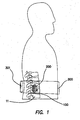
- Fig. 1 is a lateral cross sectional view of the disclosed spinal implant system in its relation to the spine of a patient.
- the system is intended for lumbar spinal vertebrae 11 located in the low back side of the human body.
- the spinal implant system comprises an implanted spinal pump 200 which delivers biological agents such as BMP-2 to an interbody spinal cage 100 that is substantially doughnut shaped.
- the spinal implant system also comprises an external induction unit 300 that charges and controls the spinal pump 200 and via an inductive link.
- the induction unit 300 comprises an inductive charger and control unit 301.
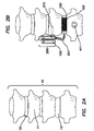
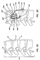
- Figs. 2a and 2c show the front (anterior) and lateral side view respectively of the lumbar spine 10, spinal nerve 15, and normal vertebrae discs 12 before the replacement of an interbody disc 13 with the interbody spinal cage 100.
- Figs. 2b and 2d show the anterior and lateral side view respectively of the lumbar spine 10, spinal nerve 15, and normal vertebrae discs 12 after the replacement of the interbody disc 13 with the interbody spinal cage 100.
- the system configuration includes the implantable pump 200 coupled to both the adjacent lumbar spinal vertebrae 11 and the interbody cage 100.
- the interbody spinal cage 100 is specifically configured to work with the implantable spinal pump 200.
- the interbody spinal cage 100 is placed in between two adjacent vertebrae 11 into the space where the interbody disc 13 previously occupied.
- the implantable spinal pump 200 is then securely mounted to the adjacent vertebra 11 via a bracket 211 and a fastening screw 212.
- the spinal pump 200 is coupled to the interbody spinal cage 100 via a catheter 207.
- a piezoelectric motor or linear actuator 205 disposed on top of the spinal pump 200 controls the release of the biological agents 103 such as BMP-2 from a reservoir 201 within the spinal pump 200.
- the spinal pump 200 is powered and controlled wirelessly by an external belt unit 300 seen in Fig. 1 via a plurality of pump inductive coils 208.
- two accelerometers 410, 411 may be coupled to the system in order to monitor the progress of the fusion process by detecting relative motion between the two adjacent vertebrae 11.
- the spinal pump 200 is a standard piston-style pump known in the art in which the osteogenetic agent 103 such as BMP is stored in a reservoir 201.
- the osteogenetic agent 103 is propelled out of an outlet port 206 by means of a plunger 202.
- Plunger motion is provided by a worm gear 203 which is actuated by the piezoelectric motor or linear actuator 205.
- the osteogenetic agent 103 is pushed out of the reservoir 201 when the motor 205 and a pump electrical control system 400 are energized by the pump inductive coils 208.
- the reservoir 201 is refilled by driving the worm gear 203 backwards while accessing the reservoir 201 with a syringe needle (not shown) via a self-sealing refill port 209.
- the piezoelectric motor or linear actuator 205 is an actuator such as a squiggle motor known in the art as an extremely small ultrasonic piezoelectric linear motor suitable for use in highly miniaturized devices. These simple, robust piezoelectric motors can be scaled down to much smaller sizes than electromagnetic motors without significant loss of power efficiency which makes them ideal for the current application.
- a squiggle motor consists of several piezoelectric ceramic actuators (not shown) coupled to a threaded nut and a pinion 204 with the mating of the worm gear 203 inside. The rotating nut turns the worm gear 203, creating a smooth in-and-out linear motion of the plunger 202 along the worm gear 203. Thread friction drives the shaft, directly converting rotary motion to linear motion.
- linear actuators are capable of nanometer resolution and high force output (5 Newtons) at speeds ranging from 1 ⁇ m/second to 10 mm/second.
- the motor operates from 2.8 to 5.5 VDC sources and draw 100mW to 900W when moving, depending on motor speed and load.
- the piezoelectric motor 205 will hold its last position within the reservoir 201 when completely powered down.
- the advantage of using a squiggle motor as the piezoelectric motor 205 is that it generates no magnetic fields and can be made from non-ferrous metals to ensure MRI compatibility.
- the osteogenetic agent or agents 103 expelled from the output port 206 of the reservoir 201 travels through the catheter 207 and to the inlet port 104 of the interbody spinal cage 100.
- a plurality of accelerometers 410, 411 may be coupled to the system as seen in Fig. 4 .
- the spine pump accelerometer 410 is coupled directly to the spine pump 200 while the vertebra accelerometer 411 is electronically coupled to the spine pump 200 by means know in the art and physically coupled to the vertebra 11 located beneath the spinal cage 100 by means known in the art.
- Each accelerometer 410, 411 comprises a corresponding reference axis 413, 414 so as to enable monitoring of the progress of the bone fusion by monitoring the difference in motion of the two adjacent bone vertebrae 11 that the interbody spinal cage 100 is coupled to. It is important to note that because the reference axes 413, 414 may not be perfectly aligned, simple comparison between individual axes may not be sufficient.
- Figs. 5a-5d are isometric depictions of the interbody spinal cage 100.
- the interbody spinal cage 100 comprises a cage body 101 that acts as a plumbing system to distribute the osteogenetic agent 103 that enters the inlet port 104 and into a main internal channel 107 as best seen in Figs. 5b-5d .
- the osteogenetic agent 103 is diverted into a network of internal flow sub-channels 106 and finally out of the cage body 101 through a plurality of outlet pores 105 into an absorbable collagen sponge 102 that resides within an inner cavity of the spinal cage 100 as seen in Fig. 3a .
- the internal flow sub-channels 106 and outlet pores 105 allow for the osteogenetic fluid 103 to be evenly distributed throughout the collagen sponge 102 ensuring even and consistent bone formation in and around the interbody spinal cage 100.
- FIG. 5b an isometric vertical cross section of the interbody spinal cage 100 is shown which displays the main internal channel 107 and internal system of sub-channels 106 which link the inlet port 104 to the plurality of outlet pores 105.
- the network of internal sub-channels 106 are disposed both above and below the main internal channel 107.
- Fig. 5c is an isometric horizontal cross section of the interbody spinal cage 100 which shows the main internal channel 107 as defined circumferentially around an inner radius of the internal spinal cage 100 and links the inlet port 104 to the network of internal sub-channels 106 and then to the outlet pores 105.
- Fig. 5c is an isometric horizontal cross section of the interbody spinal cage 100 which shows the main internal channel 107 as defined circumferentially around an inner radius of the internal spinal cage 100 and links the inlet port 104 to the network of internal sub-channels 106 and then to the outlet pores 105.
- FIG. 5d is a magnified perspective cross sectional view of the external surface of the cage body 101 and the outlet pores 105. It is to be expressly understood however that the specific configuration of the main internal channel 107 and the network of internal sub-channels 106 shown in Figs. 5a-5d , namely the main internal channel 107 being defined circumferentially about an inner radius with five periodic sub-channels 106 extending above and five periodic sub-channels 106 extending below, is for illustrative purposes only. Any configuration that uniformly and evenly distributes an osteogenetic agent about an absorbable sponge using a main channel with smaller sub-channels extending therefrom may be used without departing from the original scope of the invention.
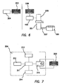
- Fig. 6 is a functional block diagram of the current system showing how the power received from the inductive charger and control unit 301 which comprises a belt electronic control system 304 coupled to a set of belt charger coils 303.
- the inductive charger and control unit 301 activates the piezoelectric motor 205 by means of a set pump charger coils 308 coupled to pump electrical control system 400. Once properly energized, the piezoelectric motor 205 in turn drives the plunger 202 to push the osteogenetic agent 103 out of the reservoir 201, through the catheter 207, and into the interbody spinal cage 100.
- Fig. 7 is a schematic representation of the electronic control system 304 portion of the inductive charger and control unit 301 in the belt 300.
- the electronic control system 304 comprises an inductive voltage generator circuit 315 on a printed circuit board and inductive belt charger coils 303 for wireless recharging.
- the electrical control system 304 further comprises a microcontroller 311 that manages a short-range wireless communication chip 312 and a display 313 as is known in the art.
- the microcontroller 311 receives a set of dosing instructions from a clinician via the wireless communication chip 312.
- the microcontroller 311 then relays those instructions on to the induction voltage generator 315. It is in this fashion that the dosing schedule or duration relayed to the spine pump 200 may be altered or changed mid treatment of the patient.
- the wireless communication chip 312 may be any wireless receiving/transmitting device, such as a Bluetooth ® chip or other similar device.
- the display 313 may be any visual screen known in the art such as a computer monitor or the like.
- the entire belt electrical control system 304 is powered by a battery 314, which may be recharged from a wall socket standard in the art.
- Fig. 8 is an orthographic representation of the belt 300 comprising of the inductive charger and control unit 301 coupled to a strap 305.
- the inductive charger and control unit 301 is enclosed in the back of the strap 305 facing the spine pump 200 implanted in the lumbar section of the human spine 10.
- the patient wraps the strap 305 of the belt 300 around their waist with the inductive charger and control unit 301 substantially over the area where the spinal pump 200 is implanted.
- the patient couples to the two opposing ends of the strap 305 together by means of a buckle or by other means known in the art so that the belt 300 remains in a stationary position as the spine pump 200 recharges.
- the patient may remain mobile while their implanted spine pump 200 is being recharged. Once recharged, the patient may decouple the opposing ends of the strap 305 and thus remove the belt 300 from around their waist.
- the inductive charger and control unit 301 portion of the belt 300 may then be plugged into a wall socket as is known in the art so that it may be sufficiently energized and ready for when the spine pump 200 is once again depleted.
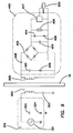
- Fig. 9 is a schematic diagram of the induction voltage generator circuit 315 and the pump electrical control system 400.
- the power to the plump electrical control system 400 on the right is provided by the induction voltage generator circuit 315 on the left using inductive coupling through a portion of human skin 16.
- the power is transmitted inductively at 200 kHz, which is rectified by a diode bridge 402 in the pump electrical control unit 400 for use by a piezoelectric pump driver circuit 407 to drive the spine pump 200.
- Fig. 10 is a three dimensional representation of the components depicted in Fig. 9 , including both the internal implantable components as well as the external components for wireless control and recharging through the portion of human skin 16.
- the induction voltage generator circuit 315 generates alternating current by means of an alternating current source 321 that energizes the belt charger coils 303 inside of a ferrite enclosure 307.
- the pump electrical control system 400 receives the generated power and control signals from the pump inductive coils 208 and drives the piezoelectric driver circuit 407.
- the piezoelectric driver circuit 407 employs a diffusion model algorithm acting as a traffic manager governing the spine pump 200 and/or piezoelectric motor 205.
- the diffusion model permits a systematic and targeted osteogenetic agent 103 delivery into the spinal region 10 by predicting achievable volumes of distribution for therapeutic agents based on the established transport and chemical kinetics models.
- the model can be simulated in a computer-aided analysis before the actual placement procedure, thus reducing the need for trial-and-error animal experimentation or intuitive dosing in human trials.
- the diffusion model is used to describe the drug dispersion in the spinal disc 12 space due to both diffusion and convection. Specifically, spine geometry, drug properties, catheter dimensions and placement, and injection method are considered in this model. Other terms such as drug decomposition, chemical kinetic reaction, and bio-elimination can be incorporated to improve the accuracy of the prediction model.
- the spine 10 including the ACS region is partitioned into small triangular and quadrilateral elements using Delaunay triangulation.
- Each small finite volume is linked to its neighbors so as to form a logically connected computational mesh, which can be generated by grid generation software such as Fluent 2007.
- the grid sizes need to be large enough to minimize the number of volume elements for calculations yet small enough to be able to spatially resolve the anatomical properties of the fusion area.
- the flow and mass transfer equations are enforced over the computational domain consisting of these meshes.
- the drug delivery to the spine 10 is simply modeled as inserting aqueous solution consisting of drug solutes into the porous ACS via an infusion catheter.
- the aqueous solution is assumed to be an incompressible Newtonian fluid whose motion can be described by the mass and momentum conservation equation. Additionally, the drug distribution is described by the species transport and chemical kinetics equations.
- the diffusion model consists of two parts: the flow inside the catheter and the flow in the ACS.
- Equation 1 For the flow inside the catheter 207, the model divides the space inside the lumen of the catheter 207 into small finite elements.
- the fluid flow between the finite elements is modeled with the continuity and Navier-Stokes equations as shown in Equations 1 and 2, respectively.
- the Navier-Stokes equation (Eq 2) describes that the momentum of the fluid flow is conserved. It states that any change in fluid velocity in the catheter 207 (the left-hand side of the equation) is due to the pressure gradient (caused by the spine pump 200) and resistance of the flow due to fluid viscosity.
- ⁇ ⁇ ⁇ v ⁇ f - ⁇ ⁇ ⁇ p + ⁇ ⁇ ⁇ ⁇ 2 ⁇ v ⁇ f
- the flow inside the ACS is modeled as the fluid flow in a porous medium.
- the ACS is partitioned into small finite elements and the flow between these elements is modeled with the continuity equation and Darcy's Law as shown in Equations 4 and 5, respectively.
- the continuity equation (Eq 4) describes that the loss of fluid in the flow is due to the absorption into the porous medium.
- the completeness of the diffusion model is captured in the boundary condition assumptions listed below.
- the infusion flow rate or pressure and concentration of drug are assumed to be constant.
- the same boundary conditions are assumed as in the inside.
- Equation 1-6 The six partial differential equations (Eq 1-6) are applied to the discrete volumes in the model to produce a set of non-linear algebraic equations for the entire system. These equations are solved with proper boundary condition using the iterative Newton-Krylov method and simulated using commercial fluid dynamics software such as Fluent.
- the power for the piezoelectric motor 205 is provided by the transcutaneous power transmission via an inductive non-contact link.
- the inductive link consists of two resonance magnetic circuits, namely the induction voltage generator circuit 315 assembled externally on a belt, and the pump electronic control system 400 as part of the implanted system.
- the inductivities of the two resonant magnetic circuits are realized by two coils, pump induction coils 208 and belt charger coils 303.
- the two coils 208, 303 when facing each other form a transformer which allows energy transfer from the induction voltage generator circuit 315 to the pump electronic control system 400.
- Inductive links have been investigated with regard to optimization of efficiency of power transfer and the tolerance to coupling coil misalignment. All these links are designed to operate at a fixed frequency at 200 kHz.
- the transfer resonant circuit is series-tuned with a voltage source with two transistors switching the rails of power supply in the electrical control system 304 in the belt 300.
- An oscillator generates the 200 kHz transmission frequency.
- Equation 7 describes the resonant equation used to derive the required number of turns in the coils.
- the number of turns required for the belt charger coils 303 is calculated to be 18 turns.
- M 2 ⁇ nV o V in
- the induction voltage generator circuit 315 of the inductive charger and control unit 301 comprises H-bridge power switching stages that provide a high frequency 200 kHz alternating polarity square wave voltage into a resonant LC tank comprising the belt charger coils 303 and a first belt capacitor 323.
- An additional RC circuit comprising of a second belt capacitor 322 and a belt resistor 321 provides high frequency EMI filtering to reduce unwanted EMI radiation from entering into the LC tank. Without the presence of the pump electronic control system 400 the charge of the LC tank will reside above the resonant frequency of the LC tank (200 kHz) therefore negligible current will flow through the LC thank and thus only a very low intensity magnetic field will be present.
- the pump electronic control system 400 comes within approximately 2-3 inches from the induction voltage generator circuit 315, the charge of the circuit will lower to the switching frequency of the induction voltage generator circuit 315. The magnetic flux will then induce current to flow into the pump induction coils 208. Tuning of the pump electronic control system 400 is achieved with selecting the appropriate value of a first pump capacitor 408 with relation to the load provided by the diode bridge 402. The alternating current in the pump induction coils 208 is full wave rectified by the diode bridge 402.
- the bus voltage of the raw rectified voltage is clamped by a Zener diode 404 which has a current limit resistor 406 to set the unloaded current of the resonant circuit
- a second pump capacitor 403 provides filtering to reduce the remaining 400 kHz ripple voltage appearing after the diode bridge 402.
- a third pump capacitor 405 and an RC circuit comprising a fourth pump capacitor 401 and a pump resistor 409 provide EMI filtering.
- the piezoelectric pump driver circuit 407 steps the raw bus voltage down to a stable 5V direct current capable of powering the plunger 202 of the spine pump 200.
- the sensory apparatus noted by the invention provides input data so as to form a homeostatic loop, hence a regulated process using boundary conditions can attenuated and be adaptable to stimuli from local sensory data set.
- the current system comprising the two accelerometer sensors 410, 411 are used to monitor the progress of fusion between the two spinal bone segments.
- the difference in acceleration of the two vertebras 11 above and below the spinal cage 100 should be within a tolerance factor as shown in Equation 9.
- the accelerometer sensors 410, 411 detect the sum of the acceleration of the bone segment and the acceleration due to gravity. As a result, the acceleration due to gravity must be subtracted dynamically from the sensor output as shown in Equation 10.
- the two accelerometer 410, 411 sensor outputs are calibrated when stationary, i.e. the outputs of the two accelerometers 410, 411 are the same, for a period of time.
Landscapes
- Health & Medical Sciences (AREA)
- Engineering & Computer Science (AREA)
- Biomedical Technology (AREA)
- Public Health (AREA)
- Heart & Thoracic Surgery (AREA)
- Life Sciences & Earth Sciences (AREA)
- Animal Behavior & Ethology (AREA)
- General Health & Medical Sciences (AREA)
- Veterinary Medicine (AREA)
- Anesthesiology (AREA)
- Hematology (AREA)
- Vascular Medicine (AREA)
- Neurology (AREA)
- Orthopedic Medicine & Surgery (AREA)
- Cardiology (AREA)
- Oral & Maxillofacial Surgery (AREA)
- Transplantation (AREA)
- Dermatology (AREA)
- Medical Informatics (AREA)
- Prostheses (AREA)
- Surgical Instruments (AREA)
- Infusion, Injection, And Reservoir Apparatuses (AREA)
Description
- The invention relates to the field of implantable drug delivery systems, specifically to a remotely activated piezoelectric pump for the controlled delivery of biological agents to the disc space and spine.
- Scientists and spinal surgeons have demonstrated that a genetically produced protein, recombinant human bone morphogenetic protein-2, or rhBMP-2, has the ability to stimulate a patient's own cells to make more bone. This finding has obvious beneficial implications for the treatment of many bone fractures and bone defects. More importantly, though, rhBMP-2 can be tremendously beneficial to patients undergoing spinal fusion. RhBMP-2 will eliminate the need for bone transplantation from the pelvis. It may also more reliably and more quickly produce fusion of spinal vertebrae. It may even reduce the need for the implantation of spinal rods and screws.
- Back pain is one of the 15 most commonly treated medical conditions in the United States today and is second only to the common cold as the most common reason for physician visits. Back pain not only has a profound effect on patients, it has an exceedingly high societal cost. Back pain is the second most common cause of lost productive time of the pain disorders and results in the largest amount of total lost time. It has been stated that of all medical conditions, back pain results in the most lost productivity. It is estimated that the direct and indirect costs associated with the disorder are approximately 50 billion dollars per year in the United States alone. Although back pain is multifactorial, degenerative disc disease is often involved in the pathogenesis and subsequent propagation of lower back pain. The disc space is composed of disc and surrounding annulus fibrosus. As the disc degenerates hypertrophy is increased in order to support the body weight, eventually leading to back pain.
- The achievement of a bony fusion is necessary for bony regeneration and healing, and is crucial to the success of many orthopedic procedures. In the spine alone, it is estimated that more than 300,000 spinal fusion procedures are performed each year in the United States.
- Traditionally, spinal fusions have been performed by decorticating the host bone, and laying down autograft from the iliac crest to achieve a bony "in-situ" fusion. With the advent and popularity of instrumentation for spinal fusions (i.e. pedicle screws), adjacent segments could now be held together, immobilizing them, thus enhancing the fusion rate. However, even with the use of iliac crest autograft and spinal fixation, the development of a biologic fusion-i.e., new bone formation at the fusion site, is not consistent. Spinal fixation allows for short term mechanical stabilization, but lacks the capacity to produce a consistent biologic fusion. Iliad crest autografts have associated morbidities related to the harvesting, including pain at the donor site. Moreover, the consistency of the bone harvested is dependent on patient's intrinsic bone quality and the surgeon's ability to harvest a significant amount of bone needed for a bony fusion. The need for a bone graft substitute that can consistently lead to bony fusions without the need for iliac crest autografts has resulted in the production of bone graft substitutes, such as demineralized bone matrix (DBM). DBM is a bone graft extender, made of allograft, which has the capacity to be osteoconductive, that is, serve as a bridge between two bone chips to facilitate a fusion. DBM, however, is not capable of forming new bone (osteoinductive).
- The commercialization of recombinant human bone morphogenetic protein-2 (BMP-2) has lead to a product that has osteoinductive properties that may be used to consistently produce a bony fusion. Currently, BMP-2 is FDA approved as a replacement for autograft in anterior lumbar interbody fusion (ALIF) using an anterior cage. It is marketed as INFUSE Bone Graft by Medtronics, Inc. INFUSE is made up of recombinant BMP-2 and absorbable collagen sponge (ACS; from bovine Achilles tendon). In a typical operation, BMP-2 is added to the ACS for a minimum of 15 minutes prior to implantation to ensure adequate binding of BMP-2. Once added to ACS, the BMP-2 must be used within 2 hours. The mean residence time of BMP-2 after implantation has been measured in a rat femoral only model implantation model to be 7.8 days. The maximum level of BMP-2 detected in the circulation was 0.1% of the implanted dose after six hours. In a rat long bone ectopic implant model, the mean residence time ranged from 3.6 to 4.6 days (McKay-p. 72). In human patients, BMP-2 is estimated to be present at the implant site for 3-4 weeks, and is cleared from the blood by the liver and excreted via the urine. Histology from animal models suggests that the ACS is reabsorbed in 4-12 weeks.
- Although BMP-2 is only FDA approved for anterior lumbar fusions, it has already been used in many different types of spinal fusion surgeries, including posterolateral fusions, and anterior cervical fusions. The posterolateral fusions appear to be effective with BMP-2 (although there was concern that it may actually work too well, and cause spinal stenosis). The anterior cervical fusions were effective from the standpoint of cervical fusions, but often induced tracheal-esophageal swelling, leading to emergency intubations in some patients. BMP-2 for human bones is used at the concentration of 1.5 mag BMP-2 per 1 cc of solution. In a typical anterior lumbar fusion, the cage is filled with 4 cc of collagen sponge, saturated with 4 cc of the 1.5 mg/cc BMP-2 solution.
- The current limitations of the BMP-2 technology are as follows:
- i) BMP-2 is soaked into a collagen sponge. When the sponge is implanted, any squeezing or manipulation of the sponge results in loss of BMP-2, making the delivery technique inefficient, ii) BMP-2 half-life and time in circulation is short, usually less than a week, and an average fusion takes 3-6 months to complete. iii) Current BMP-2 has to be delivered at massive quantities compared to what is actually needed (milligram doses, as opposed to nanogram or mircogram doses-of-what-is-needed), costing health insurance and consumers up to $8,000 to $10,000 per implant. Moreover, increased amounts of BMP-2 placed in the cervical or lumbar spine can lead to a tremendous amount of swelling. iv) BMP-2 delivery is not well directed, and is only passively absorbed. As a result, BMP-2 placed posterolaterally has the potential of fusing too much, leading to spinal stenosis. BMP-2 placed in the anterior cervical spine leads to swelling, from the BMP-2 passively leaking into the adjacent soft tissue. v) Fusion is established purely via a radiographic impression of bone formation via x-rays or CT-scan. No physiological monitoring of motion is placed to establish that a fusion has been established.
- The infusion of growth factors to the intervertebral disc has been explored by various authors in the prior art. All the infusions, however, have been via direct one time infusions, or in experimental models via an external catheter.
-
WO 2008/030832 discloses controlled release devices for fusion of osteal structures. -
WO 2005/032658 discloses a user interface for external charger for implantable medical device. -
WO 2009/092067 discloses a valveless impedance pump drug delivery system.US 2008/025987 refers to the release of BMP, bioactive agents and/or cells via a pump into a carrier matrix in a patient. - What is needed is apparatus that provides continuous infusion of various growth factors into the disc space to preserve it, instead of removing and fusing it in order to alleviate the thousands of patients currently suffering from chronic low back pain.
- The invention described herein is directed specifically to the infusion of biological agents to the spine and disc space. Although the concept of delivery of biological agents is similar, different devices will be tailor made for delivery depending on location of placement (i.e. posterior versus anterior spinal column, or intervertebral disc). Moreover, the biological agent to be used will be different, depending on the disease process to be treated. For instance, in the degenerating disc, it may be used for the direct infusion of biological growth factors to preserve degenerating discs. In the case where the interbody disc is removed during surgery, it may be placed into an interbody graft to slowly release bMP-2 placed for an interbody fusion. It may also be placed for posterolateral fusion.
- The present disclosure also describes an apparatus that allows an architecture for constructing a remotely activated piezoelectric pump for delivery of biological agents to the intervertebral disc and spine. Furthermore, the current device provides the physician with a parametric bone development model relative to a parametric delivery of dose, duration and structural adhesion of the bone formation as a measure of BMP-2 infusion as characterized by differentiation and growth of chondrocytes from the proliferation zone to the hypertrophying one. These two cellular processes are controlled by a complex signaling regulatory loop between different biochemical signals, whose production depends on the current cell density, constituting a coupled cell-chemical system. The current invention employs a mathematical model that enables the regulation as well as attenuation of the process by extending and generalizing the model to enhance and optimize the delivery of BMP-2 in a regulated manner. A reaction-diffusion regulatory loop between the medicating agents and the disc space is measured by the use of a predictable algorithm. The model represented as a set of equations is further solved within a finite element framework, getting am estimation of the spatial distribution, growth of the bone structure and formation. The results obtained are assumed to be qualitatively similar to the actual physiological ones and quantitatively close to some available experimental data noted by clinical studies.
- An object of the current invention is to provide a patient with a metronomic infusion of BMP-2 over the course of a fusion. The piezoelectric pump currently proposed will be able to deliver biological agents such as BMP-2 in a controlled fashion, allowing a more sustained infusion of BMP-2 of up to 3 months.
- Fusions will be divided into interbody anterior fusions and posterolateral fusions. For anterior interbody fusions, a bony femoral allograft, PEEK cage, titanium cage, or titanium expandable cage is used in ALIFs or in anterior spine surgery. For posterolateral fusions, the pump will be coupled to a irrigating catheter so that it can be placed in the posterolateral gutter to deliver BMP-2 over the bony fusion.
- Another object of the current invention is to store the BMP-2 in an implant reservoir, which may be accessed externally and refilled multiple times with the use of a syringe. The BMP-2 content in the reservoir is then delivered into the spine disc via a small pump.
- It is further an object of the invention to employ a micro piezoelectric actuator such as a squiggle motor, which is a type of extremely small ultrasonic piezo linear motor suitable for use in highly miniaturized devices. These simple, robust piezo motors can be scaled down to much smaller sizes than electromagnetic motors without significant loss of power efficiency, which makes them ideal for this implant application.
- Furthermore, is an additional object of the invention to enclose the piezoelectric pump so that it is protected in a PEEK or titanium housing that is capable of withstanding impacts and changes in pressure within the spinal column due to body motion. The titanium housing is designed to fit the specific indication and anatomy of the spine in which it will be implanted.
- In another embodiment, the invention comprises a pump whose actuation can be energized and controlled from an inductive power source. The pump and its electronics will remain passive until power is received from the control units via inductive coils. The control unit communicates to the implant over the inductive link for on/off control of the pump and to adjust the rate of infusion of the BMP-2. When energized and control signals are received from the inductive coupling, the pump releases BMP-2 into a delivery catheter at the commanded rate, allowing the control unit to adjust the rate of infusion of BMP-2. In addition, the inductive power energizes a plurality of mechanosensors whose values can be queried via the said inductive communication link.
- Another object of the invention is to direct intradiscal delivery of BMP-2 via a delivery catheter to irrigation channels in the interbody cage so that it is not just absorbed in a passive manner, but is directed and irrigating the specific fusion site. The irrigation channels are shaped and configured so that BMP-2 is delivered equally throughout the interbody cage.
- In another embodiment of the invention, two mechanosensors are placed, one within the pumping unit and a second on the adjacent vertebra. The mechanosensors provide information on how the fusion is progressing on a mechanical basis by physiological monitoring of relative motion between the two vertebras above and below the fusion disc. The data on the progress of the fusion between the two spinal bone segments, which is sent via the inductive communication link, helps a physician monitor the progress of the fusion and ascertain whether an optimal fusion has taken place. When the two bone segments are totally fused, the difference in acceleration of the two vertebras should be become negligible.
- It is yet another object of the invention is to provide the concept of restoration. Instead of removing and fusing a disc space as is done in the prior art, the current invention provides a constant infusion of biological agents into the disc space to preserve its integrity and to repair a disc that is damaged from degenerative disease. The infusion is performed by an implanted pump which is capable of being refilled subcutaneously via an external needle, allowing for varying concentrations and types of growth factors to be infused directly into the disc space.
- The invention can be better visualized by turning now to the following drawings wherein like elements are referenced by like numerals.
-
-
Fig. 1 is a lateral cross sectional view of the spinal pump in its relation to the spine of a patient. -
Fig. 2a is a frontal lumbar view of the spinal column of a patient before placement of the spinal pump and interbody spinal cage. -
Fig. 2b is a frontal lumbar view of the spinal column of a patient after placement of the spinal pump and interbody spinal cage. -
Fig. 2c is a side lumbar view of the spinal column of a patent before placement of the spinal pump and interbody spinal cage. -
Fig. 2d is a side lumbar view of the spinal column of a patient after placement of the spinal pump and interbody spinal cage. -
Fig. 3a is a frontal plan view of the spinal pump and interbody spinal cage and their respective components. -
Fig. 3b is a magnified plan view of the spinal pump assembly shown inFig. 3a . -
Fig. 4 is a magnified side plan view of the spinal pump assembly with accelerometers coupled to the spinal pump. -
Fig. 5a is a magnified isometric view of the interbody spinal cage assembly showing the inlet port as well as the outlet pores. -
Fig. 5b is an isometric vertical cross section of the interbody spinal cage showing the internal system of channels that connect the inlet port to the outlet pores. -
Fig. 5c is an isometric horizontal cross section of the interbody spinal cage showing the main internal channel which connects the inlet port to the outlet pores. -
Fig. 5d is a magnified isometric vertical cross sectional view showing the outlet pores of the interbody spinal cage. -
Fig. 6 is a block diagram demonstrating how power that is received from an inductive charger activates a piezoelectric motor that drives a plunger that pushes medicating agent out of a reservoir contained within the spinal pump. -
Fig. 7 is a schematic diagram representing the inductive charger in a belt. -
Fig. 8 is an orthographic view of the inductive charger in a belt. -
Fig. 9 is a schematic circuit diagram of the electronic circuits contained within the spinal pump, including the inductive coupling of the charger. -
Fig. 10 is an orthographic view of the electronic circuits contained within the spinal pump, including the inductive coupling of the charger. - The invention and its various embodiments can how be better understood by turning to the following detailed description of the preferred embodiments which are presented as illustrated examples of the invention defined in the claims. It is expressly understood that the invention as defined by the claims may be broader than the illustrated embodiments described below.
- Unless defined otherwise, all technical and scientific terms used herein have the same meanings as commonly understood by one of ordinary skill in the art to which this invention belongs. Although any methods and materials similar or equivalent to those described herein can be used in the practice or testing of the present invention, the devices, and materials are now described.
- "Absorbable Collagen Sponge" as used herein refers to the sponge in the center of the carrier matrix designed to eventually be broken down and absorbed by the body as bone grows through it. It is made up of collagen which is the main protein of connective tissue in animals and the most abundant protein in mammals. Collagen has great tensile strength, and is the main component of fascia, cartilage, ligaments, tendons, bone and skin.
- "Anterior lumbar fusion" as used herein refers to an operation done on the front (the anterior region) of the lower spine. Fusion surgery helps two or more bones grow together into one solid bone. Fusion cages are new devices, essentially hollow screws filled with bone graft, that help the bones of the spine heal together firmly. Surgeons use this procedure when patients have symptoms from disc degeneration, disc herniation, or spinal instability.
- "Anterior Lumbar Interbody Fusion Device" as used herein refers to the allograft spacers similar to those produced by Synthes North America to meet. the specific demands of spinal applications. "Bone Morphogenetic Proteins (BMP)" as used herein refers to a group of growth factors and cytokines known for their ability to induce the formation of bone and cartilage.
- "Carrier Matrix" as used herein refers to biomaterials for the orthopedic implant market which, when placed in a bone defect, provide scaffolding through and around which the patient's new bone will grow, gradually replacing the carrier matrix as the target site heals.
- "Comprising" as used herein refers to including, but not limited to, whatever follows the word "comprising". Thus, use of the term "comprising" indicates that the listed elements are required or mandatory, but that other elements are optional and may or may not be present. Additionally, unless otherwise noted, exemplary lists of compounds or devices should not be construed as limiting; instead, it should be understood that such lists admit to additional, suitable items not explicitly indicated.
- "Controlled Administration System" as used herein refers to a system which provides localized delivery either continuously or intermittently.
- "Inductive Power" as used herein refers to powering electronics using electromagnetic induction. A supplying induction coil sends energy through inductive coupling to a receiving inductive coil in an electrical device, which utilizes the energy. Because there is a small gap between the two coils, inductive charging is one kind of short-distance wireless energy transfer.
- "Interbody spinal cages" are rigid (i.e. titanium, PEEK, or allograft) spacers, usually cylindrical, that are placed in the disc space. The cages are porous and allow the bone graft to grow from the vertebral body through the cage and into the next vertebral body.
- "Localized Delivery" as used herein refers to non-systemic delivery to a site within approximately 10 cm of the site where bone growth is desired.
- "Osteogenic" as used herein refers to the ability to generate or stimulate bone growth.
- "Osteoconduction" as used herein refers to the ability to stimulate the attachment, migration, and distribution of vascular and osteogenic cells within the carrier matrix material.
- "Piezoelectric" as used herein refers to the ability of some materials to generate an electric field or electric potential in response to applied mechanical stress. The piezoelectric effect is reversible in that materials exhibiting the direct piezoelectric effect (the production of an electric potential when stress is applied) also exhibit the reverse piezoelectric effect (the production of stress and/or strain when an electric field is applied).
- "PEEK", or Polyether-etherketone, is a hard radiolucent plastic that is used in conjunction with carbon fiber reinforcement or as pure PEEK. Most manufacturers who use PEEK use radio marker dots so the surgeon can see where the implant meets the vertebral body endplate. Numerous companies (Zimmer Spine, Surgicraft, SCIENT'X, and Depuy Spine) have all developed lines of interbody fusion devices using PEEK technology.
- The following mathematical symbols used herein refer to its definitions as follow: Q is infusate flow rate; p is fluid density;
v f is fluid velocity vector in the catheter; µ is fluid viscosity; ε is tissue porosity; p is infusion fluid pressure;∇ p is pressure gradient; Db is bulk diffusivity; De is effective diffusion tensor;C f = Concentration of drug;v i is fluid velocity in the porous tissue; D e is mean effective diffusivity, k is first order rate constant accounting for drug reaction; is Hydraulic conductivity tensor, which is a function of fluid viscosity µ and effective tissue permeability tensor κ;v i ,∇ Ct is convection term; D i∇ Ct is diffusion flux;


-
Fig. 1 is a lateral cross sectional view of the disclosed spinal implant system in its relation to the spine of a patient. The system is intended for lumbarspinal vertebrae 11 located in the low back side of the human body. The spinal implant system comprises an implantedspinal pump 200 which delivers biological agents such as BMP-2 to an interbodyspinal cage 100 that is substantially doughnut shaped. The spinal implant system also comprises anexternal induction unit 300 that charges and controls thespinal pump 200 and via an inductive link. Theinduction unit 300 comprises an inductive charger andcontrol unit 301. -
Figs. 2a and2c show the front (anterior) and lateral side view respectively of thelumbar spine 10,spinal nerve 15, andnormal vertebrae discs 12 before the replacement of aninterbody disc 13 with the interbodyspinal cage 100.Figs. 2b and2d show the anterior and lateral side view respectively of thelumbar spine 10,spinal nerve 15, andnormal vertebrae discs 12 after the replacement of theinterbody disc 13 with the interbodyspinal cage 100. The system configuration includes theimplantable pump 200 coupled to both the adjacent lumbarspinal vertebrae 11 and theinterbody cage 100. The interbodyspinal cage 100 is specifically configured to work with the implantablespinal pump 200. The interbodyspinal cage 100 is placed in between twoadjacent vertebrae 11 into the space where theinterbody disc 13 previously occupied. The implantablespinal pump 200 is then securely mounted to theadjacent vertebra 11 via abracket 211 and afastening screw 212. Thespinal pump 200 is coupled to the interbodyspinal cage 100 via acatheter 207. A piezoelectric motor orlinear actuator 205 disposed on top of thespinal pump 200 controls the release of thebiological agents 103 such as BMP-2 from areservoir 201 within thespinal pump 200. Thespinal pump 200 is powered and controlled wirelessly by anexternal belt unit 300 seen inFig. 1 via a plurality of pumpinductive coils 208. Additionally, twoaccelerometers adjacent vertebrae 11. - Turning now to
Figs. 3a and3b which provides a more detailed depiction of thespinal pump 200 and theinterbody cage 100, the various detailed components of the pumping system can now be seen. Thespinal pump 200 is a standard piston-style pump known in the art in which theosteogenetic agent 103 such as BMP is stored in areservoir 201. Theosteogenetic agent 103 is propelled out of anoutlet port 206 by means of aplunger 202. Plunger motion is provided by aworm gear 203 which is actuated by the piezoelectric motor orlinear actuator 205. Theosteogenetic agent 103 is pushed out of thereservoir 201 when themotor 205 and a pumpelectrical control system 400 are energized by the pumpinductive coils 208. Thereservoir 201 is refilled by driving theworm gear 203 backwards while accessing thereservoir 201 with a syringe needle (not shown) via a self-sealingrefill port 209. - The piezoelectric motor or
linear actuator 205 is an actuator such as a squiggle motor known in the art as an extremely small ultrasonic piezoelectric linear motor suitable for use in highly miniaturized devices. These simple, robust piezoelectric motors can be scaled down to much smaller sizes than electromagnetic motors without significant loss of power efficiency which makes them ideal for the current application. A squiggle motor consists of several piezoelectric ceramic actuators (not shown) coupled to a threaded nut and apinion 204 with the mating of theworm gear 203 inside. The rotating nut turns theworm gear 203, creating a smooth in-and-out linear motion of theplunger 202 along theworm gear 203. Thread friction drives the shaft, directly converting rotary motion to linear motion. These linear actuators are capable of nanometer resolution and high force output (5 Newtons) at speeds ranging from 1 µm/second to 10 mm/second. The motor operates from 2.8 to 5.5 VDC sources and draw 100mW to 900W when moving, depending on motor speed and load. Thepiezoelectric motor 205 will hold its last position within thereservoir 201 when completely powered down. The advantage of using a squiggle motor as thepiezoelectric motor 205 is that it generates no magnetic fields and can be made from non-ferrous metals to ensure MRI compatibility. The osteogenetic agent oragents 103 expelled from theoutput port 206 of thereservoir 201 travels through thecatheter 207 and to theinlet port 104 of the interbodyspinal cage 100. - In another embodiment, a plurality of
accelerometers Fig. 4 . Thespine pump accelerometer 410 is coupled directly to thespine pump 200 while thevertebra accelerometer 411 is electronically coupled to thespine pump 200 by means know in the art and physically coupled to thevertebra 11 located beneath thespinal cage 100 by means known in the art. Eachaccelerometer corresponding reference axis adjacent bone vertebrae 11 that the interbodyspinal cage 100 is coupled to. It is important to note that because the reference axes 413, 414 may not be perfectly aligned, simple comparison between individual axes may not be sufficient. -
Figs. 5a-5d are isometric depictions of the interbodyspinal cage 100. The interbodyspinal cage 100 comprises acage body 101 that acts as a plumbing system to distribute theosteogenetic agent 103 that enters theinlet port 104 and into a maininternal channel 107 as best seen inFigs. 5b-5d . From the maininternal channel 107, theosteogenetic agent 103 is diverted into a network of internal flow sub-channels 106 and finally out of thecage body 101 through a plurality of outlet pores 105 into anabsorbable collagen sponge 102 that resides within an inner cavity of thespinal cage 100 as seen inFig. 3a . The internal flow sub-channels 106 and outlet pores 105 allow for theosteogenetic fluid 103 to be evenly distributed throughout thecollagen sponge 102 ensuring even and consistent bone formation in and around the interbodyspinal cage 100. - Returning to
Fig. 5b , an isometric vertical cross section of the interbodyspinal cage 100 is shown which displays the maininternal channel 107 and internal system ofsub-channels 106 which link theinlet port 104 to the plurality of outlet pores 105. Here it can be seen that the network ofinternal sub-channels 106 are disposed both above and below the maininternal channel 107.Fig. 5c is an isometric horizontal cross section of the interbodyspinal cage 100 which shows the maininternal channel 107 as defined circumferentially around an inner radius of the internalspinal cage 100 and links theinlet port 104 to the network ofinternal sub-channels 106 and then to the outlet pores 105.Fig. 5d is a magnified perspective cross sectional view of the external surface of thecage body 101 and the outlet pores 105. It is to be expressly understood however that the specific configuration of the maininternal channel 107 and the network ofinternal sub-channels 106 shown inFigs. 5a-5d , namely the maininternal channel 107 being defined circumferentially about an inner radius with fiveperiodic sub-channels 106 extending above and fiveperiodic sub-channels 106 extending below, is for illustrative purposes only. Any configuration that uniformly and evenly distributes an osteogenetic agent about an absorbable sponge using a main channel with smaller sub-channels extending therefrom may be used without departing from the original scope of the invention. -
Fig. 6 is a functional block diagram of the current system showing how the power received from the inductive charger andcontrol unit 301 which comprises a beltelectronic control system 304 coupled to a set of belt charger coils 303. The inductive charger andcontrol unit 301 activates thepiezoelectric motor 205 by means of a set pump charger coils 308 coupled to pumpelectrical control system 400. Once properly energized, thepiezoelectric motor 205 in turn drives theplunger 202 to push theosteogenetic agent 103 out of thereservoir 201, through thecatheter 207, and into the interbodyspinal cage 100. -
Fig. 7 is a schematic representation of theelectronic control system 304 portion of the inductive charger andcontrol unit 301 in thebelt 300. Theelectronic control system 304 comprises an inductivevoltage generator circuit 315 on a printed circuit board and inductive belt charger coils 303 for wireless recharging. Theelectrical control system 304 further comprises amicrocontroller 311 that manages a short-rangewireless communication chip 312 and adisplay 313 as is known in the art. Themicrocontroller 311 receives a set of dosing instructions from a clinician via thewireless communication chip 312. Themicrocontroller 311 then relays those instructions on to theinduction voltage generator 315. It is in this fashion that the dosing schedule or duration relayed to thespine pump 200 may be altered or changed mid treatment of the patient. Thewireless communication chip 312 may be any wireless receiving/transmitting device, such as a Bluetooth ® chip or other similar device. Thedisplay 313 may be any visual screen known in the art such as a computer monitor or the like. The entire beltelectrical control system 304 is powered by abattery 314, which may be recharged from a wall socket standard in the art. -
Fig. 8 is an orthographic representation of thebelt 300 comprising of the inductive charger andcontrol unit 301 coupled to astrap 305. The inductive charger andcontrol unit 301 is enclosed in the back of thestrap 305 facing thespine pump 200 implanted in the lumbar section of thehuman spine 10. When charging of thespine pump 200 is required, the patient wraps thestrap 305 of thebelt 300 around their waist with the inductive charger andcontrol unit 301 substantially over the area where thespinal pump 200 is implanted. The patient then couples to the two opposing ends of thestrap 305 together by means of a buckle or by other means known in the art so that thebelt 300 remains in a stationary position as thespine pump 200 recharges. It is in this fashion that the patient may remain mobile while their implantedspine pump 200 is being recharged. Once recharged, the patient may decouple the opposing ends of thestrap 305 and thus remove thebelt 300 from around their waist. The inductive charger andcontrol unit 301 portion of thebelt 300 may then be plugged into a wall socket as is known in the art so that it may be sufficiently energized and ready for when thespine pump 200 is once again depleted. -
Fig. 9 is a schematic diagram of the inductionvoltage generator circuit 315 and the pumpelectrical control system 400. The power to the plumpelectrical control system 400 on the right is provided by the inductionvoltage generator circuit 315 on the left using inductive coupling through a portion ofhuman skin 16. The power is transmitted inductively at 200 kHz, which is rectified by adiode bridge 402 in the pumpelectrical control unit 400 for use by a piezoelectricpump driver circuit 407 to drive thespine pump 200. -
Fig. 10 is a three dimensional representation of the components depicted inFig. 9 , including both the internal implantable components as well as the external components for wireless control and recharging through the portion ofhuman skin 16. The inductionvoltage generator circuit 315 generates alternating current by means of an alternatingcurrent source 321 that energizes the belt charger coils 303 inside of aferrite enclosure 307. The pumpelectrical control system 400 receives the generated power and control signals from the pumpinductive coils 208 and drives thepiezoelectric driver circuit 407. - In one embodiment of the current device, the
piezoelectric driver circuit 407 employs a diffusion model algorithm acting as a traffic manager governing thespine pump 200 and/orpiezoelectric motor 205. The diffusion model permits a systematic and targetedosteogenetic agent 103 delivery into thespinal region 10 by predicting achievable volumes of distribution for therapeutic agents based on the established transport and chemical kinetics models. The model can be simulated in a computer-aided analysis before the actual placement procedure, thus reducing the need for trial-and-error animal experimentation or intuitive dosing in human trials. The diffusion model is used to describe the drug dispersion in thespinal disc 12 space due to both diffusion and convection. Specifically, spine geometry, drug properties, catheter dimensions and placement, and injection method are considered in this model. Other terms such as drug decomposition, chemical kinetic reaction, and bio-elimination can be incorporated to improve the accuracy of the prediction model. - The
spine 10 including the ACS region is partitioned into small triangular and quadrilateral elements using Delaunay triangulation. Each small finite volume is linked to its neighbors so as to form a logically connected computational mesh, which can be generated by grid generation software such as Fluent 2007. The grid sizes need to be large enough to minimize the number of volume elements for calculations yet small enough to be able to spatially resolve the anatomical properties of the fusion area. The flow and mass transfer equations are enforced over the computational domain consisting of these meshes. - The drug delivery to the
spine 10 is simply modeled as inserting aqueous solution consisting of drug solutes into the porous ACS via an infusion catheter. The aqueous solution is assumed to be an incompressible Newtonian fluid whose motion can be described by the mass and momentum conservation equation. Additionally, the drug distribution is described by the species transport and chemical kinetics equations. The diffusion model consists of two parts: the flow inside the catheter and the flow in the ACS. - For the flow inside the
catheter 207, the model divides the space inside the lumen of thecatheter 207 into small finite elements. The fluid flow between the finite elements is modeled with the continuity and Navier-Stokes equations as shown in Equations 1 and 2, respectively. The continuity equation (Eq 1) describes that the fluid is incompressible.
- The Navier-Stokes equation (Eq 2) describes that the momentum of the fluid flow is conserved. It states that any change in fluid velocity in the catheter 207 (the left-hand side of the equation) is due to the pressure gradient (caused by the spine pump 200) and resistance of the flow due to fluid viscosity.

- The movement of the drug molecules inside the
catheter 207 due to the flow can be modeled with the species transport equation as shown in Equation 3. It states that the change in concentration of the molecules due to diffusion and convection (the left-hand side of the equation) depends on the divergent of the product of the diffusivity and concentration gradient of the molecules in the fluid.
- The flow inside the ACS is modeled as the fluid flow in a porous medium. The ACS is partitioned into small finite elements and the flow between these elements is modeled with the continuity equation and Darcy's Law as shown in Equations 4 and 5, respectively. The continuity equation (Eq 4) describes that the loss of fluid in the flow is due to the absorption into the porous medium. The fluid velocity in tissue is related to average fluid velocity through porous tissue,
v t =εv p , through the porosity. At the tip of thecatheter 207, the average fluid velocity is the same as the fluid velocity coming out of the catheter 207:v p =v f . The amount of fluid loss captured in the sink term is a function of the difference between the spinal fluid pressure and the venous pressure: SB = f(p ··· pv .).
- The fluid dynamics in the porous ACS is embodied in Darcy's Law (Eq 5), which states that the momentum of the fluid flow is conserved. It states that any change in fluid velocity in the ACS (the left-hand side of the equation) is due to the pressure gradient (caused by the flow out of the catheter 207) and resistance of the medium to the flow.

- The movement of the drug molecules inside the ACS due to the flow described in Eq 5 can be modeled with the species transport equation as shown in Equation 6. It states that the change in concentration of the molecules due to diffusion and convection (the left-hand side of the equation) depends on the divergent of the product of the diffusivity tensor of the ACS medium and concentration gradient of the molecules in the fluid. The accuracy of the model can be improved by incorporating the loss of drug molecules due to decomposition and bio-elimination.

- The completeness of the diffusion model is captured in the boundary condition assumptions listed below. At the inlet of the
catheter 207, the infusion flow rate or pressure and concentration of drug are assumed to be constant. At the interior wall inside the lumen of thecatheter 207, the flow is assumed no slip,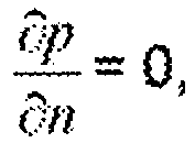
catheter 207 wall,n .∇ Cf = 0 andv f = 0. At the outer surface of thecatheter 207, the same boundary conditions are assumed as in the inside. At the tip of thecatheter 207, the continuity of flow is assumed:v f | luman =v Com =v i , and, plumen = p Cout, and Cf | lumen = Ct . Molecule transfer through permeable boundary is only one way; drug molecules can lease but cannot return. Bio-elimination "sink term" is assumed as a function of the difference between interstitial pressure and venous pressure: SB = f(p···pv ). - The six partial differential equations (Eq 1-6) are applied to the discrete volumes in the model to produce a set of non-linear algebraic equations for the entire system. These equations are solved with proper boundary condition using the iterative Newton-Krylov method and simulated using commercial fluid dynamics software such as Fluent.
- In another embodiment, the power for the
piezoelectric motor 205 is provided by the transcutaneous power transmission via an inductive non-contact link. The inductive link consists of two resonance magnetic circuits, namely the inductionvoltage generator circuit 315 assembled externally on a belt, and the pumpelectronic control system 400 as part of the implanted system. The inductivities of the two resonant magnetic circuits are realized by two coils,pump induction coils 208 and belt charger coils 303. The twocoils voltage generator circuit 315 to the pumpelectronic control system 400. Inductive links have been investigated with regard to optimization of efficiency of power transfer and the tolerance to coupling coil misalignment. All these links are designed to operate at a fixed frequency at 200 kHz. - The transfer resonant circuit is series-tuned with a voltage source with two transistors switching the rails of power supply in the
electrical control system 304 in thebelt 300. An oscillator generates the 200 kHz transmission frequency. Equation 7 describes the resonant equation used to derive the required number of turns in the coils.
- Given the frequency at 200 kHz and a capacitor at 0.47 uF, the number of turns required for the belt charger coils 303 is calculated to be 18 turns. The voltage gain for the transformer circuit is shown in Equation 8, where the turn ratio n=Np/Ns. Given Vin = 24 V and Vo = 8 Vpp, the number of turns required for the pump induction coils 208 is approximately 45 turns.

- Returning to
Fig. 9 , the inductionvoltage generator circuit 315 of the inductive charger andcontrol unit 301 comprises H-bridge power switching stages that provide ahigh frequency 200 kHz alternating polarity square wave voltage into a resonant LC tank comprising the belt charger coils 303 and afirst belt capacitor 323. An additional RC circuit comprising of asecond belt capacitor 322 and abelt resistor 321 provides high frequency EMI filtering to reduce unwanted EMI radiation from entering into the LC tank. Without the presence of the pumpelectronic control system 400 the charge of the LC tank will reside above the resonant frequency of the LC tank (200 kHz) therefore negligible current will flow through the LC thank and thus only a very low intensity magnetic field will be present. Once the pumpelectronic control system 400 comes within approximately 2-3 inches from the inductionvoltage generator circuit 315, the charge of the circuit will lower to the switching frequency of the inductionvoltage generator circuit 315. The magnetic flux will then induce current to flow into the pump induction coils 208. Tuning of the pumpelectronic control system 400 is achieved with selecting the appropriate value of afirst pump capacitor 408 with relation to the load provided by thediode bridge 402. The alternating current in the pump induction coils 208 is full wave rectified by thediode bridge 402. The bus voltage of the raw rectified voltage is clamped by aZener diode 404 which has acurrent limit resistor 406 to set the unloaded current of the resonant circuit Asecond pump capacitor 403 provides filtering to reduce the remaining 400 kHz ripple voltage appearing after thediode bridge 402. Athird pump capacitor 405 and an RC circuit comprising afourth pump capacitor 401 and apump resistor 409 provide EMI filtering. The piezoelectricpump driver circuit 407 steps the raw bus voltage down to a stable 5V direct current capable of powering theplunger 202 of thespine pump 200. - In another embodiment, the sensory apparatus noted by the invention provides input data so as to form a homeostatic loop, hence a regulated process using boundary conditions can attenuated and be adaptable to stimuli from local sensory data set.
- In one embodiment, the current system comprising the two
accelerometer sensors vertebras 11 above and below thespinal cage 100 should be within a tolerance factor as shown in Equation 9.
- However, the
accelerometer sensors Equation 10.
- The two
accelerometer accelerometers
Claims (8)
- An apparatus for delivering osteogenetic agent to the spine of a patient comprising:a implantable spine pump (200) couplable to a vertebra (11) of the patient;an external removable induction charger (300) for supplying power to the spine pump (200);a spinal cage (100) insertable between two adjacent vertebrae (11) of the patient and couplable to the spine pump (200), wherein the spinal cage (100) is substantially doughnut shaped,characterized in that the spinal cage (100) further comprises:an absorbable sponge (102) disposed within the center of the spinal cage (100);a main internal channel (107) defined circumferentially about an inner radius of the spinal cage (100); anda network of sub-channels (106) coupled to and extending from the main internal channel (107).
- The apparatus of claim 1 where the spine pump (200) comprises:a pump control system (400);a reservoir (201);a piezoelectric motor (205) coupled to and controlled by the pump control system (400);a plurality of pump induction coils (208) coupled to the pump control system (400); andmeans for the piezoelectric motor (205) to dispense the osteogenetic agent from the reservoir (201).
- The apparatus of any of the preceding claims where the external removable induction charger (300) for supplying power to the spine pump comprises:a strap (305) coupled to both ends of the induction charger (301); andmeans for coupling the opposing ends of the strap (305) not coupled to the induction charger (301) together so as to keep the induction charger (301) substantially stationary.
- The apparatus of claim 3 where the induction charger (301) comprises:a control system (304), the control system (304) comprisinga microcontroller (311);a induction voltage generator (315) coupled to the microcontroller (311);a wireless communication chip (312) coupled to the microcontroller (311);a display (313) coupled to the microcontroller (311); anda battery (314) coupled to the microcontroller (311); anda set of induction coils (303) coupled to the control system (304) through the induction voltage generator (315).
- The apparatus of claim 2 where the spine pump (200) further comprises a plurality of accelerometers (410, 411) coupled to the spine pump (200), and
wherein at least one accelerometer (411) is also coupled beneath the spinal cage (100). - The apparatus of claim 2 further comprising means for the spine pump (200) to deliver the osteogenetic agent systematically and evenly through the spinal cage (100) by a diffusion model stored within the pump control system (400).
- The apparatus of any of the preceding claims 2-6 where the reservoir (201) comprises means (209) for refilling of the osteogenetic agent by a syringe.
- The apparatus of any of the claims 4-6 where the battery (314) of the induction charger control system (304) comprises means for recharging through an external wall outlet.
Applications Claiming Priority (2)
| Application Number | Priority Date | Filing Date | Title |
|---|---|---|---|
| US12/581,785 US8827986B2 (en) | 2009-10-19 | 2009-10-19 | Remotely activated piezoelectric pump for delivery of biological agents to the intervertebral disc and spine |
| PCT/US2010/053151 WO2011049924A2 (en) | 2009-10-19 | 2010-10-19 | A remotely activated piezoelectric pump for delivery of biological agents to the intervertebral disc and spine |
Publications (3)
| Publication Number | Publication Date |
|---|---|
| EP2490732A2 EP2490732A2 (en) | 2012-08-29 |
| EP2490732A4 EP2490732A4 (en) | 2013-08-14 |
| EP2490732B1 true EP2490732B1 (en) | 2015-06-17 |
Family
ID=43879867
Family Applications (1)
| Application Number | Title | Priority Date | Filing Date |
|---|---|---|---|
| EP10825505.0A Not-in-force EP2490732B1 (en) | 2009-10-19 | 2010-10-19 | A remotely activated piezoelectric pump for delivery of biological agents to the intervertebral disc and spine |
Country Status (7)
| Country | Link |
|---|---|
| US (2) | US8827986B2 (en) |
| EP (1) | EP2490732B1 (en) |
| CN (1) | CN102665797B (en) |
| AU (1) | AU2010308284A1 (en) |
| CA (1) | CA2778278C (en) |
| RU (1) | RU2012115486A (en) |
| WO (1) | WO2011049924A2 (en) |
Families Citing this family (51)
| Publication number | Priority date | Publication date | Assignee | Title |
|---|---|---|---|---|
| US8241331B2 (en) * | 2007-11-08 | 2012-08-14 | Spine21 Ltd. | Spinal implant having a post-operative adjustable dimension |
| US10842645B2 (en) * | 2008-08-13 | 2020-11-24 | Smed-Ta/Td, Llc | Orthopaedic implant with porous structural member |
| US8287572B2 (en) | 2009-02-11 | 2012-10-16 | Howmedica Osteonics Corp. | Intervertebral implant with integrated fixation |
| JP5415627B2 (en) * | 2010-01-25 | 2014-02-12 | ジアンス ベターライフ メディカル カンパニー リミテッド | Ear module and open ear listening device |
| WO2012160173A1 (en) * | 2011-05-25 | 2012-11-29 | Micro-Beam Sa | System comprising a secondary device with a piezoelectric actuator wirelessly supplied and controlled by a primary device |
| US9949692B2 (en) | 2012-12-21 | 2018-04-24 | Canary Medical Inc. | Stent graft monitoring assembly and method of use thereof |
| CN103083108B (en) * | 2013-01-29 | 2015-05-20 | 北京大学第三医院 | Spinal cord mechanical compression device |
| CN112168143A (en) | 2013-03-15 | 2021-01-05 | 威廉·L·亨特 | Devices, systems, and methods for monitoring hip replacements |
| CN110384575B (en) | 2013-03-15 | 2023-11-17 | 卡纳里医疗公司 | Bracket monitoring components and how to use them |
| US20140277530A1 (en) * | 2013-03-15 | 2014-09-18 | Smed-Ta/Td, Llc | Fixation of bone implants |
| US9968408B1 (en) | 2013-03-15 | 2018-05-15 | Nuvasive, Inc. | Spinal balance assessment |
| EP3013283B8 (en) | 2013-06-23 | 2021-03-03 | Canary Medical Inc. | Devices, systems and methods for monitoring knee replacements |
| US9504842B2 (en) * | 2013-07-23 | 2016-11-29 | Ado Holding Sa | Electronic medical system with implantable medical device, having wireless power supply transfer |
| CA2990821C (en) | 2014-06-25 | 2024-02-06 | William L. Hunter | Devices, systems and methods for using and monitoring spinal implants |
| CA2990816A1 (en) | 2014-06-25 | 2015-12-30 | William L. Hunter | Devices, systems and methods for using and monitoring heart valves |
| EP3160393A4 (en) | 2014-06-25 | 2018-12-12 | Canary Medical Inc. | Devices, systems and methods for using and monitoring implants |
| CA2990825A1 (en) | 2014-06-25 | 2015-12-30 | William L. Hunter | Devices, systems and methods for using and monitoring orthopedic hardware |
| CA2992263A1 (en) | 2014-06-25 | 2015-12-30 | Canary Medical Inc. | Devices, systems and methods for using and monitoring tubes in body passageways |
| WO2016044651A1 (en) | 2014-09-17 | 2016-03-24 | Canary Medical Inc. | Devices, systems and methods for using and monitoring medical devices |
| US10603182B2 (en) | 2015-01-14 | 2020-03-31 | Stryker European Holdings I, Llc | Spinal implant with fluid delivery capabilities |
| AU2016200179B2 (en) | 2015-01-14 | 2020-09-17 | Stryker European Operations Holdings Llc | Spinal implant with porous and solid surfaces |
| US10695099B2 (en) | 2015-02-13 | 2020-06-30 | Nuvasive, Inc. | Systems and methods for planning, performing, and assessing spinal correction during surgery |
| US10292831B2 (en) | 2015-03-20 | 2019-05-21 | Intelligent Implants Limited | System and method for dynamically stimulating bone growth |
| CA2930123A1 (en) | 2015-05-18 | 2016-11-18 | Stryker European Holdings I, Llc | Partially resorbable implants and methods |
| EP4104878A1 (en) | 2015-08-20 | 2022-12-21 | Tandem Diabetes Care, Inc. | Drive mechanism for infusion pump |
| US10617880B2 (en) | 2015-12-08 | 2020-04-14 | Intelligent Implants Limited | System and method for an electrical implant device with increased patient compliance |
| US9770591B2 (en) | 2015-12-29 | 2017-09-26 | Rainbow Medical Ltd. | Disc therapy |
| US11484706B2 (en) | 2015-12-29 | 2022-11-01 | Discure Technologies Ltd | Disc therapy |
| EP3868294B1 (en) * | 2016-03-02 | 2024-04-24 | Nuvasive, Inc. | System for spinal correction surgical planning |
| IL294630B2 (en) | 2016-03-23 | 2023-12-01 | Canary Medical Inc | An implantable report processor for an alert implant |
| US10835388B2 (en) | 2017-09-20 | 2020-11-17 | Stryker European Operations Holdings Llc | Spinal implants |
| EP3749390B1 (en) | 2018-02-05 | 2026-05-06 | Tandem Diabetes Care, Inc. | Methods and systems for detecting infusion pump conditions |
| US11471297B2 (en) | 2018-10-03 | 2022-10-18 | Intelligent Implants Limited | System and method to alter electrically stimulated bone growth through electrode selection |
| CA3116287A1 (en) | 2018-10-15 | 2020-04-23 | Mazor Robotics Ltd. | Versatile multi-arm robotic surgical system |
| CN113286556A (en) | 2019-01-14 | 2021-08-20 | 纽文思公司 | Prediction of post-operative global sagittal alignment based on whole body musculoskeletal modeling and pose optimization |
| US11129658B2 (en) | 2019-02-12 | 2021-09-28 | Warsaw Orthopedic, Inc. | Bone stent and port |
| US11844706B2 (en) | 2019-03-20 | 2023-12-19 | Grabango Co. | System and method for positioning and orienting an orthopedic implant |
| CA3176873A1 (en) | 2019-06-06 | 2020-12-10 | Canary Medical Inc. | Intelligent joint prosthesis |
| US20210366610A1 (en) | 2019-06-06 | 2021-11-25 | Canary Medical Inc. | Intelligent joint prosthesis |
| EP4051375A1 (en) | 2019-11-01 | 2022-09-07 | Intelligent Implants Limited | System and method for embedding electronic components within an implant |
| CN111449810A (en) * | 2020-04-30 | 2020-07-28 | 四川大学华西医院 | Intelligent orthopedic implant for reconstruction after vertebral body resection |
| CN111700715A (en) * | 2020-04-30 | 2020-09-25 | 四川大学华西医院 | An intelligent interbody cage |
| US11502545B2 (en) * | 2020-05-29 | 2022-11-15 | Puthalath Koroth Raghuprasad | Watch charging assembly |
| US12274525B2 (en) | 2020-09-29 | 2025-04-15 | Mazor Robotics Ltd. | Systems and methods for tracking anatomical motion |
| US12465441B2 (en) | 2021-02-01 | 2025-11-11 | Mazor Robotics Ltd. | Multi-arm robotic systems and methods for identifying a target |
| US12508085B2 (en) | 2021-02-04 | 2025-12-30 | Mazor Robotics Ltd. | Systems, methods, and devices for verifying mechanical coupling between anatomical elements |
| US12582818B2 (en) | 2021-03-25 | 2026-03-24 | Intelligent Implants Limited | System and method for scaling orthopedic implant stimulation |
| US11298530B1 (en) | 2021-05-03 | 2022-04-12 | Discure Technologies Ltd. | Synergistic therapies for intervertebral disc degeneration |
| US11344721B1 (en) | 2021-08-16 | 2022-05-31 | Rainbow Medical Ltd. | Cartilage treatment |
| JP2025508412A (en) * | 2022-02-18 | 2025-03-26 | メディカルトゥリー・パテンツ・リミテッド | System for treating hypertensive patients |
| AU2024226798A1 (en) | 2023-02-21 | 2025-09-04 | Osteal Therapeutics, Inc. | Methods of local irrigation for treating fungal infections |
Family Cites Families (26)
| Publication number | Priority date | Publication date | Assignee | Title |
|---|---|---|---|---|
| US4494950A (en) * | 1982-01-19 | 1985-01-22 | The Johns Hopkins University | Plural module medication delivery system |
| GB8701731D0 (en) * | 1987-01-27 | 1987-03-04 | Patcentre Benelux Nv Sa | Pumps |
| US5571189A (en) * | 1994-05-20 | 1996-11-05 | Kuslich; Stephen D. | Expandable fabric implant for stabilizing the spinal motion segment |
| AU732421B2 (en) * | 1996-10-23 | 2001-04-26 | Warsaw Orthopedic, Inc. | Spinal spacer |
| US6889082B2 (en) * | 1997-10-09 | 2005-05-03 | Orqis Medical Corporation | Implantable heart assist system and method of applying same |
| US6482233B1 (en) * | 1998-01-29 | 2002-11-19 | Synthes(U.S.A.) | Prosthetic interbody spacer |
| US6553263B1 (en) * | 1999-07-30 | 2003-04-22 | Advanced Bionics Corporation | Implantable pulse generators using rechargeable zero-volt technology lithium-ion batteries |
| US6315769B1 (en) * | 1999-09-13 | 2001-11-13 | Medtronic, Inc. | Apparatus and method for measuring the amount of fluid contained in an implantable medical device |
| US20020169507A1 (en) * | 2000-12-14 | 2002-11-14 | David Malone | Interbody spine fusion cage |
| US20020087113A1 (en) * | 2000-12-29 | 2002-07-04 | Medtronic, Inc. | Drug management techniques for an implantable medical device |
| US8128616B2 (en) * | 2002-03-27 | 2012-03-06 | Medtronic, Inc. | System, method and implantable device for delivery of therapeutic substance |
| US7225032B2 (en) * | 2003-10-02 | 2007-05-29 | Medtronic Inc. | External power source, charger and system for an implantable medical device having thermal characteristics and method therefore |
| US8346361B2 (en) * | 2003-10-02 | 2013-01-01 | Medtronic, Inc. | User interface for external charger for implantable medical device |
| DE102004036358B4 (en) * | 2004-07-27 | 2016-11-03 | Giesecke & Devrient Gmbh | metering |
| EP1786343B1 (en) * | 2004-07-30 | 2012-05-02 | Depuy Spine, Inc. | Apparatus for treating bone and other tissue |
| WO2006055547A2 (en) * | 2004-11-15 | 2006-05-26 | Izex Technologies, Inc. | Instrumented orthopedic and other medical implants |
| US7918887B2 (en) * | 2005-03-29 | 2011-04-05 | Roche Martin W | Body parameter detecting sensor and method for detecting body parameters |
| US8642060B2 (en) * | 2006-04-24 | 2014-02-04 | Warsaw Orthopedic, Inc. | Controlled release systems and methods for osteal growth |
| US7879027B2 (en) * | 2006-04-24 | 2011-02-01 | Warsaw Orthopedic, Inc. | Controlled release devices for fusion of osteal structures |
| US7723291B2 (en) * | 2006-07-27 | 2010-05-25 | Warsaw Orthopedic, Inc. | Release of BMP, bioactive agents and/or cells via a pump into a carrier matrix |
| US20090030399A1 (en) * | 2007-07-23 | 2009-01-29 | Kamshad Raiszadeh | Drug Delivery Device and Method |
| WO2009092067A2 (en) * | 2008-01-18 | 2009-07-23 | Neurosystec Corporation | Valveless impedance pump drug delivery systems |
| WO2009134477A1 (en) * | 2008-04-29 | 2009-11-05 | Medtronic, Inc. | Therapy program modification |
| US8685093B2 (en) * | 2009-01-23 | 2014-04-01 | Warsaw Orthopedic, Inc. | Methods and systems for diagnosing, treating, or tracking spinal disorders |
| US20100222750A1 (en) * | 2009-02-27 | 2010-09-02 | Vanderbilt University | Replenishable drug delivery implant for bone and cartilage |
| US8271089B2 (en) * | 2009-04-03 | 2012-09-18 | Medtronic, Inc. | Hybrid rectification for recharging an implantable medical device |
-
2009
- 2009-10-19 US US12/581,785 patent/US8827986B2/en active Active
-
2010
- 2010-10-19 CA CA2778278A patent/CA2778278C/en not_active Expired - Fee Related
- 2010-10-19 AU AU2010308284A patent/AU2010308284A1/en not_active Abandoned
- 2010-10-19 WO PCT/US2010/053151 patent/WO2011049924A2/en not_active Ceased
- 2010-10-19 CN CN201080057764.4A patent/CN102665797B/en not_active Expired - Fee Related
- 2010-10-19 RU RU2012115486/14A patent/RU2012115486A/en not_active Application Discontinuation
- 2010-10-19 EP EP10825505.0A patent/EP2490732B1/en not_active Not-in-force
-
2011
- 2011-10-27 US US13/283,368 patent/US20120041562A1/en not_active Abandoned
Also Published As
| Publication number | Publication date |
|---|---|
| RU2012115486A (en) | 2013-11-27 |
| EP2490732A4 (en) | 2013-08-14 |
| US20120041562A1 (en) | 2012-02-16 |
| CN102665797B (en) | 2014-06-18 |
| CN102665797A (en) | 2012-09-12 |
| WO2011049924A2 (en) | 2011-04-28 |
| WO2011049924A3 (en) | 2011-09-29 |
| US20110092948A1 (en) | 2011-04-21 |
| CA2778278C (en) | 2015-12-08 |
| CA2778278A1 (en) | 2011-04-28 |
| AU2010308284A1 (en) | 2012-05-17 |
| US8827986B2 (en) | 2014-09-09 |
| EP2490732A2 (en) | 2012-08-29 |
Similar Documents
| Publication | Publication Date | Title |
|---|---|---|
| CA2778278C (en) | A remotely activated piezoelectric pump for delivery of biological agents to the intervertebral disc and spine | |
| US8016859B2 (en) | Dynamic treatment system and method of use | |
| US7993269B2 (en) | Sensor and method for spinal monitoring | |
| EP3319560B1 (en) | Spinal implant system | |
| US7072802B2 (en) | Therapy management techniques for an implantable medical device | |
| CN110475584B (en) | Spinal implant systems and methods | |
| US6482234B1 (en) | Prosthetic spinal disc | |
| Klosterhoff et al. | Wireless sensor enables longitudinal monitoring of regenerative niche mechanics during rehabilitation that enhance bone repair | |
| RU2590861C9 (en) | Implanted lubricating device | |
| US20060089642A1 (en) | Prefracture spinal implant for osteoporotic unfractured bone | |
| WO2013149134A2 (en) | Alif spinal implant | |
| CN103140168A (en) | Methods and apparatus for an inertial-based implantable sensing system for in vivo detection of spinal pseudarthrosis and adjacent segment motion in real time | |
| Williams et al. | Early resistance rehabilitation improves functional regeneration following segmental bone defect injury | |
| CN119455175B (en) | Microminiature wireless control patch type insulin pump and preparation method thereof | |
| KR20120068827A (en) | Implantable lubrication device | |
| Lamberg et al. | Effect of local TGF-β1 and IGF-1 release on implant fixation: Comparison with hydroxyapatite coating: A paired study in dogs | |
| WO2024098047A1 (en) | Device with aperture lock for medical devices | |
| Klosterhoff et al. | Real-time monitoring of mechanical cues in the regenerative niche reveal dynamic strain magnitudes that enhance bone repair | |
| Harrer | Regenerative Engineering and Rehabilitation Strategies for Bone Regeneration and Functional Restoration | |
| Nash et al. | Regenerative Rehabilitation Strategies for Complex Bone Injuries | |
| RU2712082C2 (en) | Implantable lubricating device | |
| RU2808664C2 (en) | Implantable lubricant medical device for implantation into the knee joint of a mammal | |
| Williams | Leveraging Rehabilitation and Implantable Strain Sensors to Improve Bone Healing After Traumatic Femur Fractures | |
| Mukhopadhyay et al. | Feasibility analysis of wireless power delivery to implanted sensors of XLIF patients | |
| Damsaz et al. | Bioelectrical Stimulation in Dental Implantology: Improving Osseointegration Through Biophysics |
Legal Events
| Date | Code | Title | Description |
|---|---|---|---|
| PUAI | Public reference made under article 153(3) epc to a published international application that has entered the european phase |
Free format text: ORIGINAL CODE: 0009012 |
|
| 17P | Request for examination filed |
Effective date: 20120516 |
|
| AK | Designated contracting states |
Kind code of ref document: A2 Designated state(s): AL AT BE BG CH CY CZ DE DK EE ES FI FR GB GR HR HU IE IS IT LI LT LU LV MC MK MT NL NO PL PT RO RS SE SI SK SM TR |
|
| DAX | Request for extension of the european patent (deleted) | ||
| A4 | Supplementary search report drawn up and despatched |
Effective date: 20130711 |
|
| RIC1 | Information provided on ipc code assigned before grant |
Ipc: A61M 5/142 20060101AFI20130705BHEP Ipc: A61F 2/30 20060101ALI20130705BHEP Ipc: A61F 2/28 20060101ALI20130705BHEP Ipc: A61M 5/145 20060101ALI20130705BHEP Ipc: A61M 37/00 20060101ALI20130705BHEP Ipc: A61B 17/70 20060101ALI20130705BHEP Ipc: A61F 2/44 20060101ALI20130705BHEP |
|
| 17Q | First examination report despatched |
Effective date: 20140425 |
|
| GRAP | Despatch of communication of intention to grant a patent |
Free format text: ORIGINAL CODE: EPIDOSNIGR1 |
|
| INTG | Intention to grant announced |
Effective date: 20150106 |
|
| GRAS | Grant fee paid |
Free format text: ORIGINAL CODE: EPIDOSNIGR3 |
|
| GRAA | (expected) grant |
Free format text: ORIGINAL CODE: 0009210 |
|
| AK | Designated contracting states |
Kind code of ref document: B1 Designated state(s): AL AT BE BG CH CY CZ DE DK EE ES FI FR GB GR HR HU IE IS IT LI LT LU LV MC MK MT NL NO PL PT RO RS SE SI SK SM TR |
|
| REG | Reference to a national code |
Ref country code: GB Ref legal event code: FG4D |
|
| REG | Reference to a national code |
Ref country code: CH Ref legal event code: EP |
|
| REG | Reference to a national code |
Ref country code: AT Ref legal event code: REF Ref document number: 731551 Country of ref document: AT Kind code of ref document: T Effective date: 20150715 |
|
| REG | Reference to a national code |
Ref country code: IE Ref legal event code: FG4D |
|
| REG | Reference to a national code |
Ref country code: DE Ref legal event code: R096 Ref document number: 602010025350 Country of ref document: DE |
|
| REG | Reference to a national code |
Ref country code: FR Ref legal event code: PLFP Year of fee payment: 6 |
|
| PG25 | Lapsed in a contracting state [announced via postgrant information from national office to epo] |
Ref country code: LT Free format text: LAPSE BECAUSE OF FAILURE TO SUBMIT A TRANSLATION OF THE DESCRIPTION OR TO PAY THE FEE WITHIN THE PRESCRIBED TIME-LIMIT Effective date: 20150617 Ref country code: NO Free format text: LAPSE BECAUSE OF FAILURE TO SUBMIT A TRANSLATION OF THE DESCRIPTION OR TO PAY THE FEE WITHIN THE PRESCRIBED TIME-LIMIT Effective date: 20150917 Ref country code: FI Free format text: LAPSE BECAUSE OF FAILURE TO SUBMIT A TRANSLATION OF THE DESCRIPTION OR TO PAY THE FEE WITHIN THE PRESCRIBED TIME-LIMIT Effective date: 20150617 Ref country code: HR Free format text: LAPSE BECAUSE OF FAILURE TO SUBMIT A TRANSLATION OF THE DESCRIPTION OR TO PAY THE FEE WITHIN THE PRESCRIBED TIME-LIMIT Effective date: 20150617 |
|
| REG | Reference to a national code |
Ref country code: AT Ref legal event code: MK05 Ref document number: 731551 Country of ref document: AT Kind code of ref document: T Effective date: 20150617 |
|
| REG | Reference to a national code |
Ref country code: LT Ref legal event code: MG4D Ref country code: NL Ref legal event code: MP Effective date: 20150617 |
|
| PG25 | Lapsed in a contracting state [announced via postgrant information from national office to epo] |
Ref country code: LV Free format text: LAPSE BECAUSE OF FAILURE TO SUBMIT A TRANSLATION OF THE DESCRIPTION OR TO PAY THE FEE WITHIN THE PRESCRIBED TIME-LIMIT Effective date: 20150617 Ref country code: RS Free format text: LAPSE BECAUSE OF FAILURE TO SUBMIT A TRANSLATION OF THE DESCRIPTION OR TO PAY THE FEE WITHIN THE PRESCRIBED TIME-LIMIT Effective date: 20150617 Ref country code: BG Free format text: LAPSE BECAUSE OF FAILURE TO SUBMIT A TRANSLATION OF THE DESCRIPTION OR TO PAY THE FEE WITHIN THE PRESCRIBED TIME-LIMIT Effective date: 20150917 Ref country code: GR Free format text: LAPSE BECAUSE OF FAILURE TO SUBMIT A TRANSLATION OF THE DESCRIPTION OR TO PAY THE FEE WITHIN THE PRESCRIBED TIME-LIMIT Effective date: 20150918 |
|
| PG25 | Lapsed in a contracting state [announced via postgrant information from national office to epo] |
Ref country code: EE Free format text: LAPSE BECAUSE OF FAILURE TO SUBMIT A TRANSLATION OF THE DESCRIPTION OR TO PAY THE FEE WITHIN THE PRESCRIBED TIME-LIMIT Effective date: 20150617 |
|
| PG25 | Lapsed in a contracting state [announced via postgrant information from national office to epo] |
Ref country code: PL Free format text: LAPSE BECAUSE OF FAILURE TO SUBMIT A TRANSLATION OF THE DESCRIPTION OR TO PAY THE FEE WITHIN THE PRESCRIBED TIME-LIMIT Effective date: 20150617 Ref country code: SK Free format text: LAPSE BECAUSE OF FAILURE TO SUBMIT A TRANSLATION OF THE DESCRIPTION OR TO PAY THE FEE WITHIN THE PRESCRIBED TIME-LIMIT Effective date: 20150617 Ref country code: PT Free format text: LAPSE BECAUSE OF FAILURE TO SUBMIT A TRANSLATION OF THE DESCRIPTION OR TO PAY THE FEE WITHIN THE PRESCRIBED TIME-LIMIT Effective date: 20151019 Ref country code: ES Free format text: LAPSE BECAUSE OF FAILURE TO SUBMIT A TRANSLATION OF THE DESCRIPTION OR TO PAY THE FEE WITHIN THE PRESCRIBED TIME-LIMIT Effective date: 20150617 Ref country code: AT Free format text: LAPSE BECAUSE OF FAILURE TO SUBMIT A TRANSLATION OF THE DESCRIPTION OR TO PAY THE FEE WITHIN THE PRESCRIBED TIME-LIMIT Effective date: 20150617 Ref country code: IS Free format text: LAPSE BECAUSE OF FAILURE TO SUBMIT A TRANSLATION OF THE DESCRIPTION OR TO PAY THE FEE WITHIN THE PRESCRIBED TIME-LIMIT Effective date: 20151017 Ref country code: CZ Free format text: LAPSE BECAUSE OF FAILURE TO SUBMIT A TRANSLATION OF THE DESCRIPTION OR TO PAY THE FEE WITHIN THE PRESCRIBED TIME-LIMIT Effective date: 20150617 Ref country code: RO Free format text: LAPSE BECAUSE OF NON-PAYMENT OF DUE FEES Effective date: 20150617 |
|
| REG | Reference to a national code |
Ref country code: DE Ref legal event code: R097 Ref document number: 602010025350 Country of ref document: DE |
|
| PLBE | No opposition filed within time limit |
Free format text: ORIGINAL CODE: 0009261 |
|
| STAA | Information on the status of an ep patent application or granted ep patent |
Free format text: STATUS: NO OPPOSITION FILED WITHIN TIME LIMIT |
|
| PG25 | Lapsed in a contracting state [announced via postgrant information from national office to epo] |
Ref country code: DK Free format text: LAPSE BECAUSE OF FAILURE TO SUBMIT A TRANSLATION OF THE DESCRIPTION OR TO PAY THE FEE WITHIN THE PRESCRIBED TIME-LIMIT Effective date: 20150617 Ref country code: IT Free format text: LAPSE BECAUSE OF FAILURE TO SUBMIT A TRANSLATION OF THE DESCRIPTION OR TO PAY THE FEE WITHIN THE PRESCRIBED TIME-LIMIT Effective date: 20150617 |
|
| 26N | No opposition filed |
Effective date: 20160318 |
|
| PG25 | Lapsed in a contracting state [announced via postgrant information from national office to epo] |
Ref country code: LU Free format text: LAPSE BECAUSE OF FAILURE TO SUBMIT A TRANSLATION OF THE DESCRIPTION OR TO PAY THE FEE WITHIN THE PRESCRIBED TIME-LIMIT Effective date: 20151019 |
|
| REG | Reference to a national code |
Ref country code: CH Ref legal event code: PL |
|
| PG25 | Lapsed in a contracting state [announced via postgrant information from national office to epo] |
Ref country code: MC Free format text: LAPSE BECAUSE OF FAILURE TO SUBMIT A TRANSLATION OF THE DESCRIPTION OR TO PAY THE FEE WITHIN THE PRESCRIBED TIME-LIMIT Effective date: 20150617 |
|
| REG | Reference to a national code |
Ref country code: IE Ref legal event code: MM4A |
|
| PG25 | Lapsed in a contracting state [announced via postgrant information from national office to epo] |
Ref country code: CH Free format text: LAPSE BECAUSE OF NON-PAYMENT OF DUE FEES Effective date: 20151031 Ref country code: LI Free format text: LAPSE BECAUSE OF NON-PAYMENT OF DUE FEES Effective date: 20151031 |
|
| PG25 | Lapsed in a contracting state [announced via postgrant information from national office to epo] |
Ref country code: SI Free format text: LAPSE BECAUSE OF FAILURE TO SUBMIT A TRANSLATION OF THE DESCRIPTION OR TO PAY THE FEE WITHIN THE PRESCRIBED TIME-LIMIT Effective date: 20150617 |
|
| REG | Reference to a national code |
Ref country code: FR Ref legal event code: PLFP Year of fee payment: 7 |
|
| PG25 | Lapsed in a contracting state [announced via postgrant information from national office to epo] |
Ref country code: IE Free format text: LAPSE BECAUSE OF NON-PAYMENT OF DUE FEES Effective date: 20151019 |
|
| PG25 | Lapsed in a contracting state [announced via postgrant information from national office to epo] |
Ref country code: BE Free format text: LAPSE BECAUSE OF FAILURE TO SUBMIT A TRANSLATION OF THE DESCRIPTION OR TO PAY THE FEE WITHIN THE PRESCRIBED TIME-LIMIT Effective date: 20150617 |
|
| PG25 | Lapsed in a contracting state [announced via postgrant information from national office to epo] |
Ref country code: SM Free format text: LAPSE BECAUSE OF FAILURE TO SUBMIT A TRANSLATION OF THE DESCRIPTION OR TO PAY THE FEE WITHIN THE PRESCRIBED TIME-LIMIT Effective date: 20150617 Ref country code: HU Free format text: LAPSE BECAUSE OF FAILURE TO SUBMIT A TRANSLATION OF THE DESCRIPTION OR TO PAY THE FEE WITHIN THE PRESCRIBED TIME-LIMIT; INVALID AB INITIO Effective date: 20101019 |
|
| PG25 | Lapsed in a contracting state [announced via postgrant information from national office to epo] |
Ref country code: SE Free format text: LAPSE BECAUSE OF FAILURE TO SUBMIT A TRANSLATION OF THE DESCRIPTION OR TO PAY THE FEE WITHIN THE PRESCRIBED TIME-LIMIT Effective date: 20150617 Ref country code: NL Free format text: LAPSE BECAUSE OF FAILURE TO SUBMIT A TRANSLATION OF THE DESCRIPTION OR TO PAY THE FEE WITHIN THE PRESCRIBED TIME-LIMIT Effective date: 20150617 Ref country code: CY Free format text: LAPSE BECAUSE OF FAILURE TO SUBMIT A TRANSLATION OF THE DESCRIPTION OR TO PAY THE FEE WITHIN THE PRESCRIBED TIME-LIMIT Effective date: 20150617 |
|
| PG25 | Lapsed in a contracting state [announced via postgrant information from national office to epo] |
Ref country code: MT Free format text: LAPSE BECAUSE OF FAILURE TO SUBMIT A TRANSLATION OF THE DESCRIPTION OR TO PAY THE FEE WITHIN THE PRESCRIBED TIME-LIMIT Effective date: 20150617 Ref country code: TR Free format text: LAPSE BECAUSE OF FAILURE TO SUBMIT A TRANSLATION OF THE DESCRIPTION OR TO PAY THE FEE WITHIN THE PRESCRIBED TIME-LIMIT Effective date: 20150617 |
|
| REG | Reference to a national code |
Ref country code: FR Ref legal event code: PLFP Year of fee payment: 8 |
|
| PG25 | Lapsed in a contracting state [announced via postgrant information from national office to epo] |
Ref country code: MK Free format text: LAPSE BECAUSE OF FAILURE TO SUBMIT A TRANSLATION OF THE DESCRIPTION OR TO PAY THE FEE WITHIN THE PRESCRIBED TIME-LIMIT Effective date: 20150617 |
|
| REG | Reference to a national code |
Ref country code: FR Ref legal event code: PLFP Year of fee payment: 9 |
|
| PG25 | Lapsed in a contracting state [announced via postgrant information from national office to epo] |
Ref country code: AL Free format text: LAPSE BECAUSE OF FAILURE TO SUBMIT A TRANSLATION OF THE DESCRIPTION OR TO PAY THE FEE WITHIN THE PRESCRIBED TIME-LIMIT Effective date: 20150617 |
|
| PGFP | Annual fee paid to national office [announced via postgrant information from national office to epo] |
Ref country code: FR Payment date: 20231127 Year of fee payment: 14 Ref country code: DE Payment date: 20231129 Year of fee payment: 14 |
|
| PGFP | Annual fee paid to national office [announced via postgrant information from national office to epo] |
Ref country code: GB Payment date: 20240403 Year of fee payment: 14 |
|
| REG | Reference to a national code |
Ref country code: DE Ref legal event code: R119 Ref document number: 602010025350 Country of ref document: DE |
|
| GBPC | Gb: european patent ceased through non-payment of renewal fee |
Effective date: 20241019 |
|
| PG25 | Lapsed in a contracting state [announced via postgrant information from national office to epo] |
Ref country code: DE Free format text: LAPSE BECAUSE OF NON-PAYMENT OF DUE FEES Effective date: 20250501 |
|
| PG25 | Lapsed in a contracting state [announced via postgrant information from national office to epo] |
Ref country code: GB Free format text: LAPSE BECAUSE OF NON-PAYMENT OF DUE FEES Effective date: 20241019 |
|
| PG25 | Lapsed in a contracting state [announced via postgrant information from national office to epo] |
Ref country code: FR Free format text: LAPSE BECAUSE OF NON-PAYMENT OF DUE FEES Effective date: 20241031 |