EP2490243A1 - Latch assembly and electrical switching apparatus including the same - Google Patents
Latch assembly and electrical switching apparatus including the same Download PDFInfo
- Publication number
- EP2490243A1 EP2490243A1 EP20120001012 EP12001012A EP2490243A1 EP 2490243 A1 EP2490243 A1 EP 2490243A1 EP 20120001012 EP20120001012 EP 20120001012 EP 12001012 A EP12001012 A EP 12001012A EP 2490243 A1 EP2490243 A1 EP 2490243A1
- Authority
- EP
- European Patent Office
- Prior art keywords
- latch
- shaft member
- shaft
- latch plate
- seating surface
- Prior art date
- Legal status (The legal status is an assumption and is not a legal conclusion. Google has not performed a legal analysis and makes no representation as to the accuracy of the status listed.)
- Withdrawn
Links
- 239000000463 material Substances 0.000 claims description 15
- 229910000831 Steel Inorganic materials 0.000 claims description 10
- 230000007246 mechanism Effects 0.000 claims description 10
- 239000010959 steel Substances 0.000 claims description 10
- 238000010438 heat treatment Methods 0.000 claims description 9
- 238000003825 pressing Methods 0.000 claims description 8
- 229910000653 SAE 1095 Inorganic materials 0.000 claims description 5
- 229910000639 Spring steel Inorganic materials 0.000 claims description 4
- 239000011324 bead Substances 0.000 claims description 4
- 238000000034 method Methods 0.000 description 8
- 230000008569 process Effects 0.000 description 8
- 238000005304 joining Methods 0.000 description 5
- RYGMFSIKBFXOCR-UHFFFAOYSA-N Copper Chemical compound [Cu] RYGMFSIKBFXOCR-UHFFFAOYSA-N 0.000 description 4
- 238000005219 brazing Methods 0.000 description 4
- 229910052802 copper Inorganic materials 0.000 description 4
- 239000010949 copper Substances 0.000 description 4
- 229910001220 stainless steel Inorganic materials 0.000 description 3
- 239000010935 stainless steel Substances 0.000 description 3
- 238000012360 testing method Methods 0.000 description 3
- 238000003466 welding Methods 0.000 description 3
- 230000000712 assembly Effects 0.000 description 2
- 238000000429 assembly Methods 0.000 description 2
- 230000006872 improvement Effects 0.000 description 2
- 210000003127 knee Anatomy 0.000 description 2
- 230000035515 penetration Effects 0.000 description 2
- 238000010791 quenching Methods 0.000 description 2
- XLYOFNOQVPJJNP-UHFFFAOYSA-N water Substances O XLYOFNOQVPJJNP-UHFFFAOYSA-N 0.000 description 2
- 229910000984 420 stainless steel Inorganic materials 0.000 description 1
- OKTJSMMVPCPJKN-UHFFFAOYSA-N Carbon Chemical compound [C] OKTJSMMVPCPJKN-UHFFFAOYSA-N 0.000 description 1
- 229910001566 austenite Inorganic materials 0.000 description 1
- 229910052799 carbon Inorganic materials 0.000 description 1
- 238000004140 cleaning Methods 0.000 description 1
- 238000000576 coating method Methods 0.000 description 1
- 239000013078 crystal Substances 0.000 description 1
- 238000005242 forging Methods 0.000 description 1
- 238000007373 indentation Methods 0.000 description 1
- 238000004519 manufacturing process Methods 0.000 description 1
- 239000002184 metal Substances 0.000 description 1
- 229910052751 metal Inorganic materials 0.000 description 1
- 150000001247 metal acetylides Chemical class 0.000 description 1
- 238000012986 modification Methods 0.000 description 1
- 230000004048 modification Effects 0.000 description 1
- OFNHPGDEEMZPFG-UHFFFAOYSA-N phosphanylidynenickel Chemical compound [P].[Ni] OFNHPGDEEMZPFG-UHFFFAOYSA-N 0.000 description 1
- 238000007747 plating Methods 0.000 description 1
- 230000036316 preload Effects 0.000 description 1
- 230000000171 quenching effect Effects 0.000 description 1
- 230000004044 response Effects 0.000 description 1
- 239000011435 rock Substances 0.000 description 1
- 238000005476 soldering Methods 0.000 description 1
- 238000005482 strain hardening Methods 0.000 description 1
- 238000005496 tempering Methods 0.000 description 1
- 229910000859 α-Fe Inorganic materials 0.000 description 1
Images

Classifications
-
- H—ELECTRICITY
- H01—ELECTRIC ELEMENTS
- H01H—ELECTRIC SWITCHES; RELAYS; SELECTORS; EMERGENCY PROTECTIVE DEVICES
- H01H71/00—Details of the protective switches or relays covered by groups H01H73/00 - H01H83/00
- H01H71/10—Operating or release mechanisms
- H01H71/50—Manual reset mechanisms which may be also used for manual release
- H01H71/505—Latching devices between operating and release mechanism
-
- H—ELECTRICITY
- H01—ELECTRIC ELEMENTS
- H01H—ELECTRIC SWITCHES; RELAYS; SELECTORS; EMERGENCY PROTECTIVE DEVICES
- H01H11/00—Apparatus or processes specially adapted for the manufacture of electric switches
-
- Y—GENERAL TAGGING OF NEW TECHNOLOGICAL DEVELOPMENTS; GENERAL TAGGING OF CROSS-SECTIONAL TECHNOLOGIES SPANNING OVER SEVERAL SECTIONS OF THE IPC; TECHNICAL SUBJECTS COVERED BY FORMER USPC CROSS-REFERENCE ART COLLECTIONS [XRACs] AND DIGESTS
- Y10—TECHNICAL SUBJECTS COVERED BY FORMER USPC
- Y10T—TECHNICAL SUBJECTS COVERED BY FORMER US CLASSIFICATION
- Y10T292/00—Closure fasteners
- Y10T292/08—Bolts
- Y10T292/096—Sliding
-
- Y—GENERAL TAGGING OF NEW TECHNOLOGICAL DEVELOPMENTS; GENERAL TAGGING OF CROSS-SECTIONAL TECHNOLOGIES SPANNING OVER SEVERAL SECTIONS OF THE IPC; TECHNICAL SUBJECTS COVERED BY FORMER USPC CROSS-REFERENCE ART COLLECTIONS [XRACs] AND DIGESTS
- Y10—TECHNICAL SUBJECTS COVERED BY FORMER USPC
- Y10T—TECHNICAL SUBJECTS COVERED BY FORMER US CLASSIFICATION
- Y10T292/00—Closure fasteners
- Y10T292/08—Bolts
- Y10T292/096—Sliding
- Y10T292/1014—Operating means
Definitions
- the disclosed concept pertains generally to electrical switching apparatus and, more particularly, to circuit breakers.
- the disclosed concept also pertains to latch assemblies for such circuit breakers.
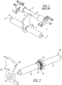
- a latch assembly 2 includes three components: a D-shaft 4, a latch plate 6 and a latch shaft 8.
- the latch plate 6 and the latch shaft 8 are joined together (i.e., by copper brazing; by soldering; by welding followed by heat treating) and the latch plate 6 rotates about the longitudinal axis 9 of the latch shaft 8.
- the D-shaft 4 blocks (near D-shaft slot 10 when in a corresponding range of suitable axial positions), as shown, or allows the movement of the latch plate 6 (through the D-shaft slot 10 when in a corresponding suitable axial position (not shown)) as the D-shaft 4 rotates (e.g., clockwise with respect to Figure 1 ) on its longitudinal axis 9.
- the latch shaft 8 and the D-shaft 4 both rotate about their respective longitudinal axes, which are disposed a fixed distance apart.
- the latch assembly 2 can only rotate clockwise (with respect to Figure 1 ) when the D-shaft 4 is suitably oriented (not shown) to allow the latch plate 6 to pass through the D-shaft slot 10.
- the strength and the hardness of the latch plate 6 and the latch shaft 8 are carefully controlled, preferably inexpensively.
- the latch plate 6 is made of 420 stainless steel and the latch shaft 8 is made of 410 stainless steel. These are copper brazed together and heat treated at the same time. However, the stainless steel will not get hard enough to hold up to life testing and, thus, the tip 12 of the latch plate 6 can deform. Also, a problem with copper brazing certain types of steel, such as 1070 stainless steel, is that the copper braze would melt when such steel is heat treated and, hence, the parts would not stay together in a heat treatment furnace.
- a latch assembly comprises: a latch plate having an opening therethrough; and a latch shaft comprising a shaft member and a positioning shoulder disposed on the shaft member, the positioning shoulder having a seating surface thereon, wherein the shaft member passes through the opening of the latch plate, wherein the latch plate engages the positioning shoulder of the shaft member, and wherein the seating surface of the shaft member is swaged to retain the latch plate to the shaft member.
- an electrical switching apparatus comprises: separable contacts; an operating mechanism structured to open and close the separable contacts; and a latch comprising: a D-shaft, a latch plate having an opening therethrough, the latch plate having a portion structured to engage the D-shaft, and a latch shaft comprising a shaft member and a positioning shoulder disposed on the shaft member, the positioning shoulder having a seating surface thereon, wherein the shaft member passes through the opening of the latch plate, wherein the latch plate engages the positioning shoulder of the shaft member, and wherein the seating surface of the shaft member is swaged to retain the latch plate to the shaft member.
- a latch comprises: a D-shaft; a latch plate having an opening therethrough, the latch plate having a portion structured to engage the D-shaft; and a latch shaft comprising a shaft member and a positioning shoulder disposed on the shaft member, the positioning shoulder having a seating surface thereon, wherein the shaft member passes through the opening of the latch plate, wherein the latch plate engages the positioning shoulder of the shaft member, and wherein the seating surface of the shaft member is swaged to retain the latch plate to the shaft member.
- number shall mean one or an integer greater than one ( i.e., a plurality).
- swaging shall mean a process of forging in which the dimensions of an item are altered using a die or dies, a swaging tool or a pressing tool. Swaging is usually a cold working process; however, it is sometimes done as a hot working process.
- the term “is swaged” as applied to an item shall mean that the structure of such item is altered by swaging.
- the disclosed concept is described in association with a circuit breaker, although the disclosed concept is applicable to a wide range of electrical switching apparatus.
- FIG 2 shows a latch plate 20 and a latch shaft 22 before assembly.
- the latch shaft 22 includes a positioning shoulder 24 and a seating surface 26 having an additional sacrificial section 28.
- the seating surface 26 of the latch shaft 22 abutting the positioning shoulder 24 is employed to locate the latch plate 20 on the latch shaft 22 as will be described in connection with Figures 3A and 3B .
- the additional sacrificial section 28 ( Figures 2 and 3A ) of the seating surface 26 is then suitably mechanically deformed (i.e., swaged) using a suitable cylindrical swaging or pressing tool 30 ( Figure 6 ), in order to retain the latch plate 20 to the shaft member 32 and lock the latch plate 20 in place.
- the mechanical deformation of the sacrificial section 28 provides the joining force.
- the fully assembled latch assembly 34 ( Figure 3B ) then undergoes a suitable heat treatment using a suitably robust industrial process as will be described.
- Figures 2 , 3A and 3B show the mechanical joining of the latch plate 20 and the latch shaft 22. This allows a wide range of material selections and heat treatments. The resulting available materials and heat treatment processes are relatively less expensive, relatively more reliable, and allow a more suitable combination of material properties (e.g., strength and toughness) than are possible with known prior brazing or welding operations.
- Figure 3A shows the latch assembly 34 having the sacrificial section 28 before swaging.
- Figure 3B shows the latch assembly 34 having a raised surface 36 after swaging.
- the latch assembly 34 includes the latch plate 20 having an opening 38 therethrough, and the latch shaft 22 having the shaft member 32 and the positioning shoulder 24 disposed on the shaft member 32.
- the positioning shoulder 24 has the seating surface 26 thereon.
- the shaft member 32 and a portion of the seating surface 26 pass through the latch plate opening 38.
- the latch plate 20 engages the shaft member positioning shoulder 24.
- the sacrificial section 28 of the shaft member seating surface 26 is swaged to retain the latch plate 20 to the shaft member 32.
- the disclosed latch plate 20 is perpendicular to the latch shaft 22. Also, it is desired that the latch edge 40 be hard enough to not deform under Hertzian contact stress (e.g., localized stresses that develop as two curved surfaces come in contact and deform slightly under the imposed loads) but not so brittle that it chips when the corresponding circuit breaker 104 ( Figure 4 ) latches.
- the roller surface 46 of the latch plate 20 is precisely placed to give a moment arm about the latch shaft 22 to get the correct load on the trip D-shaft 102 ( Figures 4 and 5 ) in order that the circuit breaker 104 can be interrupted by a trip actuator (not shown), which has, for example and without limitation, only a maximum of about two pounds of force.
- the latch plate 20 is a planar member having the latch edge 40 engaging the trip D-shaft 102 as shown in Figure 4 .
- the latch shaft 22, positioning shoulder 24 and seating surface 26 are a single piece. This can be formed, for example, on a lathe (not shown) in one operation to ensure that the single piece is concentric, has a central longitudinal axis 39, and that the positioning shoulder 24 is perpendicular to the latch shaft longitudinal axis 39.
- the disclosed concept employs 1070 or 1095 spring steel for the latch plate 20, in order to get a suitably hard latch edge 40 to prevent deformation, and a 1045 steel latch shaft 22.
- the two parts are pressed together when the parts are soft and then the latch shaft 22 is swaged to retain the latch plate 20 thereon.
- the sacrificial section 28 ( Figures 2 and 3A ) of the seating surface 26 of the latch shaft 22 is pushed into the latch plate 20 taking up any clearance and making a tight fit.
- the sacrificial section 28 portion of the seating surface 26 forms, for example and without limitation, a .020" bead of material around the opening 38 of the latch plate 20 at the raised surface 36 ( Figure 3B ) to mechanically retain the latch plate 20 to the shaft member 32 and ensure that the latch plate 20 does not come off.
- the parts are heat treated and plated. All of the formed material of the latch shaft 22 then becomes hardened to Rockwell C (HRC) 35 to HRC 40 for a 1045 steel latch shaft, in order that it will not deform during life testing.
- the latch plate 20 will then become hardened in the range of HRC 50 to HRC 55 for a 1070 or 1095 spring steel for the latch plate, in order to prevent the latch edge 40 from deforming under Hertzian contact stress.
- the Rockwell scale is a hardness scale based on the indentation hardness of a material. The Rockwell test determines the hardness by measuring the depth of penetration of an indenter under a large load compared to the penetration made by a preload. There are different scales, which are denoted by a single letter, that use different loads or indenters. The result, which is a dimensionless number, is noted by HRX where X (e.g., C for relatively harder steels) is the scale letter.
- An example heat treatment process for 1070 spring steel austenitizes e.g., without limitation, heats the steel to a temperature at which it changes crystal structure from ferrite to austenite; the presence of carbides may occur or be present during a two-phase austenitization
- a match carbon atmosphere e.g., 0.70%
- the process cycle can include heating to 1475 °F, holding for 3 to 7 minutes at temperature, quenching in water, cleaning the parts to remove quench oil, and tempering at 500 to 700 °F for one hour.
- An example plating process for the latch assembly 34 is ASTM B733 - 04(2009) Standard Specification for Autocatalytic (Electroless) Nickel-Phosphorus Coatings on Metal.
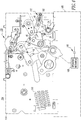
- a status indicating assembly 100 is for an electrical switching apparatus such as, for example and without limitation, a circuit breaker 104 (partially shown in simplified form).
- the circuit breaker 104 includes a housing 105 (shown in phantom line drawing), separable contacts 106 (shown in simplified form) enclosed by the housing 105, and an operating mechanism 108 (shown in simplified form) for opening and closing the separable contacts 106.
- the operating mechanism 108 includes a stored energy mechanism, which in this example includes a closing spring 110 (partially shown in phantom line drawing).
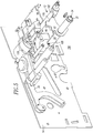
- the operating mechanism 108 also includes an opening latch or trip latch 112, which is pivotable between a latched position (as shown), and an unlatched position ( Figure 5 ).
- the stored energy mechanism (only the closing spring 110 is shown) applies force to a toggle knee 118 and closes the circuit breaker 104.
- the separable contacts 106 can remain closed and the stored energy mechanism can be recharged while the circuit breaker 104 remains closed.
- the circuit breaker separable contacts 106 are closed and the opening latch 112 is latched ( Figure 4 ). When the opening latch 112 is rotated to the open position ( Figure 5 ), the separable contacts 106 then break connection.
- the circuit breaker housing 105 further includes a pair of opposing side plates (only one side plate 114 is shown), and the status indicating assembly 100 is substantially disposed between the side plates.
- the opening latch or trip latch 112 includes the latch assembly 34 and the trip D-shaft 102.
- the latch assembly 34 is pivotally coupled to the side plates 14 (only one side plate 14 is shown) and is structured to pivot, or rock, between the latched position ( Figure 4 ) and the unlatched position ( Figure 5 ). In the latched position, the latch edge 40 engages the outer diameter of the trip D-shaft 102 and is held in place thereby.
- the trip D-shaft 102 is structured to rotate (clockwise with respect to Figure 4 ) in response to a user input (e.g., actuation of a solenoid (not shown)).
- a user input e.g., actuation of a solenoid (not shown)
- the latch edge 40 passes over the trip D-shaft 102 and enters the trip D-shaft opening 116, thereby allowing the latch assembly 34 to move into the unlatched position ( Figure 5 ).
- the disclosed concept employs a low cost, multipart, purely mechanically joined latch assembly 34.
- optimum materials can be employed for the main latch components, which are the latch plate 20 and the latch shaft 22.
- a suitably high hardness latch assembly 34 is provided without compromising the hardness during a joining operation as is the case with a prior brazed latch assembly.
- the joining operation is a swaging operation that locates the latch plate 20 on the latch shaft 22 and locks these main latch components together by only a mechanical force.
- the cylindrical swaging or pressing tool 30 ( Figure 6 ) includes a central longitudinal opening 42 for receiving the shaft member 32 and a swaging surface 44 for swaging the sacrificial section 28.
Landscapes
- Engineering & Computer Science (AREA)
- Manufacturing & Machinery (AREA)
- Breakers (AREA)
- Forging (AREA)
Abstract
A latch assembly includes a latch plate having an opening therethrough; and a latch shaft having a shaft member and a positioning shoulder disposed on the shaft member. The positioning shoulder has a seating surface thereon. The shaft member passes through the opening of the latch plate. The latch plate engages the positioning shoulder of the shaft member. The seating surface of the shaft member is swaged to retain the latch plate to the shaft member.
Description
- The disclosed concept pertains generally to electrical switching apparatus and, more particularly, to circuit breakers. The disclosed concept also pertains to latch assemblies for such circuit breakers.
- Latches are an important part of electrical switching apparatus, such as circuit breakers, and can take the form shown in
Figure 1 . Alatch assembly 2 includes three components: a D-shaft 4, a latch plate 6 and a latch shaft 8. The latch plate 6 and the latch shaft 8 are joined together (i.e., by copper brazing; by soldering; by welding followed by heat treating) and the latch plate 6 rotates about the longitudinal axis 9 of the latch shaft 8. The D-shaft 4 blocks (near D-shaft slot 10 when in a corresponding range of suitable axial positions), as shown, or allows the movement of the latch plate 6 (through the D-shaft slot 10 when in a corresponding suitable axial position (not shown)) as the D-shaft 4 rotates (e.g., clockwise with respect toFigure 1 ) on its longitudinal axis 9. The latch shaft 8 and the D-shaft 4 both rotate about their respective longitudinal axes, which are disposed a fixed distance apart. Thelatch assembly 2 can only rotate clockwise (with respect toFigure 1 ) when the D-shaft 4 is suitably oriented (not shown) to allow the latch plate 6 to pass through the D-shaft slot 10. - In order to optimize performance, the strength and the hardness of the latch plate 6 and the latch shaft 8 are carefully controlled, preferably inexpensively. For example, the latch plate 6 is made of 420 stainless steel and the latch shaft 8 is made of 410 stainless steel. These are copper brazed together and heat treated at the same time. However, the stainless steel will not get hard enough to hold up to life testing and, thus, the
tip 12 of the latch plate 6 can deform. Also, a problem with copper brazing certain types of steel, such as 1070 stainless steel, is that the copper braze would melt when such steel is heat treated and, hence, the parts would not stay together in a heat treatment furnace. - Known current practices of rigidly joining the latch plate 6 to the latch shaft 8 include brazing or welding operations. However, for example, cracks in the welds after heat treatment can be an issue with welded parts. These operations present severe limitations on the choice of materials for these components and corresponding heat treatment options. The processes available with acceptable materials limit the component hardness and/or are difficult to control in a repeatable manner in an industrial environment. Hence, there is room for improvement in latch assemblies.
- There is also room for improvement in electrical switching apparatus, such as circuit breakers, including a latch assembly.
- These needs and others are met by embodiments of the disclosed concept, which provide a latch assembly in which a latch plate and a shaft member of a latch shaft are swaged to retain the latch plate to the shaft member.
- In accordance with one aspect of the disclosed concept, a latch assembly comprises: a latch plate having an opening therethrough; and a latch shaft comprising a shaft member and a positioning shoulder disposed on the shaft member, the positioning shoulder having a seating surface thereon, wherein the shaft member passes through the opening of the latch plate, wherein the latch plate engages the positioning shoulder of the shaft member, and wherein the seating surface of the shaft member is swaged to retain the latch plate to the shaft member.
- As another aspect of the disclosed concept, an electrical switching apparatus comprises: separable contacts; an operating mechanism structured to open and close the separable contacts; and a latch comprising: a D-shaft, a latch plate having an opening therethrough, the latch plate having a portion structured to engage the D-shaft, and a latch shaft comprising a shaft member and a positioning shoulder disposed on the shaft member, the positioning shoulder having a seating surface thereon, wherein the shaft member passes through the opening of the latch plate, wherein the latch plate engages the positioning shoulder of the shaft member, and wherein the seating surface of the shaft member is swaged to retain the latch plate to the shaft member.
- As another aspect of the disclosed concept, a latch comprises: a D-shaft; a latch plate having an opening therethrough, the latch plate having a portion structured to engage the D-shaft; and a latch shaft comprising a shaft member and a positioning shoulder disposed on the shaft member, the positioning shoulder having a seating surface thereon, wherein the shaft member passes through the opening of the latch plate, wherein the latch plate engages the positioning shoulder of the shaft member, and wherein the seating surface of the shaft member is swaged to retain the latch plate to the shaft member.
- A full understanding of the disclosed concept can be gained from the following description of the preferred embodiments when read in conjunction with the accompanying drawings in which:
-
Figure 1 is an isometric view of a latch assembly including a D-shaft, a latch shaft and a latch plate. -
Figure 2 is an unassembled isometric view of a latch shaft and a latch plate in accordance with embodiments of the disclosed concept. -
Figures 3A and 3B are assembled isometric views of the latch shaft and the latch plate ofFigure 2 before and after swaging, respectively. -
Figure 4 is a side elevation view of a portion of a circuit breaker and a status indicating assembly therefor, including the latch assembly ofFigure 3B , with the circuit breaker housing and hidden components being shown in simplified form. -
Figure 5 is an isometric view of the status indicating assembly ofFigure 4 , shown in the position corresponding to the circuit breaker being discharged and open. -
Figure 6 is an isometric view of a swaging or pressing tool in accordance with embodiments of the disclosed concept. - As employed herein, the term "number" shall mean one or an integer greater than one (i.e., a plurality).
- As employed herein, the statement that two or more parts are "connected" or "coupled" together shall mean that the parts are joined together either directly or joined through one or more intermediate parts. Further, as employed herein, the statement that two or more parts are "attached" shall mean that the parts are joined together directly.
- As employed herein, the term "swaging" shall mean a process of forging in which the dimensions of an item are altered using a die or dies, a swaging tool or a pressing tool. Swaging is usually a cold working process; however, it is sometimes done as a hot working process. The term "is swaged" as applied to an item (e.g., "an item is swaged") shall mean that the structure of such item is altered by swaging.
- The disclosed concept is described in association with a circuit breaker, although the disclosed concept is applicable to a wide range of electrical switching apparatus.
-
Figure 2 shows alatch plate 20 and alatch shaft 22 before assembly. Thelatch shaft 22 includes a positioningshoulder 24 and aseating surface 26 having an additionalsacrificial section 28. Theseating surface 26 of thelatch shaft 22 abutting the positioningshoulder 24 is employed to locate thelatch plate 20 on thelatch shaft 22 as will be described in connection withFigures 3A and 3B . The additional sacrificial section 28 (Figures 2 and3A ) of theseating surface 26 is then suitably mechanically deformed (i.e., swaged) using a suitable cylindrical swaging or pressing tool 30 (Figure 6 ), in order to retain thelatch plate 20 to theshaft member 32 and lock thelatch plate 20 in place. The mechanical deformation of thesacrificial section 28 provides the joining force. The fully assembled latch assembly 34 (Figure 3B ) then undergoes a suitable heat treatment using a suitably robust industrial process as will be described. -
Figures 2 ,3A and 3B show the mechanical joining of thelatch plate 20 and thelatch shaft 22. This allows a wide range of material selections and heat treatments. The resulting available materials and heat treatment processes are relatively less expensive, relatively more reliable, and allow a more suitable combination of material properties (e.g., strength and toughness) than are possible with known prior brazing or welding operations.Figure 3A shows thelatch assembly 34 having thesacrificial section 28 before swaging.Figure 3B shows thelatch assembly 34 having a raisedsurface 36 after swaging. - The
latch assembly 34 includes thelatch plate 20 having an opening 38 therethrough, and thelatch shaft 22 having theshaft member 32 and thepositioning shoulder 24 disposed on theshaft member 32. The positioningshoulder 24 has theseating surface 26 thereon. Theshaft member 32 and a portion of theseating surface 26 pass through the latch plate opening 38. Thelatch plate 20 engages the shaftmember positioning shoulder 24. Thesacrificial section 28 of the shaftmember seating surface 26 is swaged to retain thelatch plate 20 to theshaft member 32. - The disclosed
latch plate 20 is perpendicular to thelatch shaft 22. Also, it is desired that thelatch edge 40 be hard enough to not deform under Hertzian contact stress (e.g., localized stresses that develop as two curved surfaces come in contact and deform slightly under the imposed loads) but not so brittle that it chips when the corresponding circuit breaker 104 (Figure 4 ) latches. Theroller surface 46 of thelatch plate 20 is precisely placed to give a moment arm about thelatch shaft 22 to get the correct load on the trip D-shaft 102 (Figures 4 and5 ) in order that thecircuit breaker 104 can be interrupted by a trip actuator (not shown), which has, for example and without limitation, only a maximum of about two pounds of force. Thelatch plate 20 is a planar member having thelatch edge 40 engaging the trip D-shaft 102 as shown inFigure 4 . - The
latch shaft 22, positioningshoulder 24 andseating surface 26 are a single piece. This can be formed, for example, on a lathe (not shown) in one operation to ensure that the single piece is concentric, has a centrallongitudinal axis 39, and that thepositioning shoulder 24 is perpendicular to the latch shaftlongitudinal axis 39. - The disclosed concept employs 1070 or 1095 spring steel for the
latch plate 20, in order to get a suitably hardlatch edge 40 to prevent deformation, and a 1045steel latch shaft 22. The two parts are pressed together when the parts are soft and then thelatch shaft 22 is swaged to retain thelatch plate 20 thereon. When thelatch shaft 22 is swaged, the sacrificial section 28 (Figures 2 and3A ) of theseating surface 26 of thelatch shaft 22 is pushed into thelatch plate 20 taking up any clearance and making a tight fit. Thesacrificial section 28 portion of theseating surface 26 forms, for example and without limitation, a .020" bead of material around theopening 38 of thelatch plate 20 at the raised surface 36 (Figure 3B ) to mechanically retain thelatch plate 20 to theshaft member 32 and ensure that thelatch plate 20 does not come off. - Next, the parts are heat treated and plated. All of the formed material of the
latch shaft 22 then becomes hardened to Rockwell C (HRC) 35 toHRC 40 for a 1045 steel latch shaft, in order that it will not deform during life testing. Thelatch plate 20 will then become hardened in the range of HRC 50 to HRC 55 for a 1070 or 1095 spring steel for the latch plate, in order to prevent thelatch edge 40 from deforming under Hertzian contact stress. The Rockwell scale is a hardness scale based on the indentation hardness of a material. The Rockwell test determines the hardness by measuring the depth of penetration of an indenter under a large load compared to the penetration made by a preload. There are different scales, which are denoted by a single letter, that use different loads or indenters. The result, which is a dimensionless number, is noted by HRX where X (e.g., C for relatively harder steels) is the scale letter. - An example heat treatment process for 1070 spring steel austenitizes (e.g., without limitation, heats the steel to a temperature at which it changes crystal structure from ferrite to austenite; the presence of carbides may occur or be present during a two-phase austenitization) in a match carbon atmosphere (e.g., 0.70%), quenches in water, and tempers the steel to obtain a hardness of HRC 50 to HRC 55. The process cycle can include heating to 1475 °F, holding for 3 to 7 minutes at temperature, quenching in water, cleaning the parts to remove quench oil, and tempering at 500 to 700 °F for one hour.
- An example plating process for the
latch assembly 34 is ASTM B733 - 04(2009) Standard Specification for Autocatalytic (Electroless) Nickel-Phosphorus Coatings on Metal. - Referring to
Figure 4 , astatus indicating assembly 100 is for an electrical switching apparatus such as, for example and without limitation, a circuit breaker 104 (partially shown in simplified form). Thecircuit breaker 104 includes a housing 105 (shown in phantom line drawing), separable contacts 106 (shown in simplified form) enclosed by thehousing 105, and an operating mechanism 108 (shown in simplified form) for opening and closing theseparable contacts 106. Theoperating mechanism 108 includes a stored energy mechanism, which in this example includes a closing spring 110 (partially shown in phantom line drawing). Theoperating mechanism 108 also includes an opening latch ortrip latch 112, which is pivotable between a latched position (as shown), and an unlatched position (Figure 5 ). The stored energy mechanism (only theclosing spring 110 is shown) applies force to atoggle knee 118 and closes thecircuit breaker 104. Theseparable contacts 106 can remain closed and the stored energy mechanism can be recharged while thecircuit breaker 104 remains closed. The circuit breakerseparable contacts 106 are closed and theopening latch 112 is latched (Figure 4 ). When theopening latch 112 is rotated to the open position (Figure 5 ), theseparable contacts 106 then break connection. - In the example shown and described herein, the
circuit breaker housing 105 further includes a pair of opposing side plates (only oneside plate 114 is shown), and thestatus indicating assembly 100 is substantially disposed between the side plates. The opening latch ortrip latch 112 includes thelatch assembly 34 and the trip D-shaft 102. Thelatch assembly 34 is pivotally coupled to the side plates 14 (only oneside plate 14 is shown) and is structured to pivot, or rock, between the latched position (Figure 4 ) and the unlatched position (Figure 5 ). In the latched position, thelatch edge 40 engages the outer diameter of the trip D-shaft 102 and is held in place thereby. The trip D-shaft 102 is structured to rotate (clockwise with respect toFigure 4 ) in response to a user input (e.g., actuation of a solenoid (not shown)). When the trip D-shaft 102 rotates, thelatch edge 40 passes over the trip D-shaft 102 and enters the trip D-shaft opening 116, thereby allowing thelatch assembly 34 to move into the unlatched position (Figure 5 ). - The disclosed concept employs a low cost, multipart, purely mechanically joined
latch assembly 34. As a result, optimum materials can be employed for the main latch components, which are thelatch plate 20 and thelatch shaft 22. Hence, a suitably highhardness latch assembly 34 is provided without compromising the hardness during a joining operation as is the case with a prior brazed latch assembly. The joining operation is a swaging operation that locates thelatch plate 20 on thelatch shaft 22 and locks these main latch components together by only a mechanical force. The cylindrical swaging or pressing tool 30 (Figure 6 ) includes a centrallongitudinal opening 42 for receiving theshaft member 32 and aswaging surface 44 for swaging thesacrificial section 28. - While specific embodiments of the disclosed concept have been described in detail, it will be appreciated by those skilled in the art that various modifications and alternatives to those details could be developed in light of the overall teachings of the disclosure. Accordingly, the particular arrangements disclosed are meant to be illustrative only and not limiting as to the scope of the disclosed concept which is to be given the full breadth of the claims appended and any and all equivalents thereof.
-
- 1. A latch assembly (34) comprising:
- a latch plate (20) having an opening (38) therethrough; and
- a latch shaft (22) comprising a shaft member (32) and a positioning shoulder (24) disposed on said shaft member, said positioning shoulder having a seating surface (26) thereon,
- wherein said shaft member passes through the opening of said latch plate,
- wherein said latch plate engages the positioning shoulder of said shaft member, and
- wherein the seating surface of said shaft member is swaged to retain said latch plate to said shaft member.
- 2. The latch assembly (34) of 1 wherein said shaft member retains said latch plate by only a mechanical force.
- 3. The latch assembly (34) of 1 wherein said latch plate is made of a material selected from the group consisting of 1070 spring steel and 1095 spring steel; and wherein said latch shaft is made of 1045 steel.
- 4. The latch assembly (34) of 1 wherein said latch assembly is heat treated to provide a hardness of said latch plate in the range of HRC 50 to HRC 55.
- 5. The latch assembly (34) of 4 wherein said latch assembly is plated per ASTM B733.
- 6. The latch assembly (34) of 1 wherein a portion (28) of the seating surface of said shaft member forms a bead of material (36) around the opening of said latch plate to mechanically retain said latch plate to said shaft member.
- 7. The latch assembly (34) of 1 wherein said latch shaft, the positioning shoulder and the seating surface are formed as a single piece; wherein said single piece is concentric and has a central longitudinal axis (39); and wherein the positioning shoulder is perpendicular to said central longitudinal axis.
- 8. The latch assembly (34) of 1 wherein said latch plate is a planar member having a latch edge (40).
- 9. The latch assembly (34) of 1 wherein the seating surface of said shaft member is structured to be swaged by a swaging or pressing tool (30).
- 10. The latch assembly (34) of 1 wherein said seating surface comprises a sacrificial seating surface (28) that is mechanical deformed when said sacrificial seating surface is swaged to retain said latch plate to said shaft member.
- 11. An electrical switching apparatus (104) comprising:
- separable contacts (106);
- an operating mechanism (108) structured to open and close said separable contacts; and
- a latch (112) comprising:
- a D-shaft (102),
- a latch plate (20) having an opening (38) therethrough, said latch plate having a portion (40) structured to engage said D-shaft, and
- a latch shaft (22) comprising a shaft member (32) and a positioning shoulder (24) disposed on said shaft member, said positioning shoulder having a seating surface (26) thereon,
- wherein said shaft member passes through the opening of said latch plate,
- wherein said latch plate engages the positioning shoulder of said shaft member, and
- wherein the seating surface of said shaft member is swaged to retain said latch plate to said shaft member.
- 12. The electrical switching apparatus (104) of 11 wherein said shaft member retains said latch plate by only a mechanical force.
- 13. The electrical switching apparatus (104) of 11 wherein said latch plate is made of a material selected from the group consisting of 1070 spring steel and 1095 spring steel; and wherein said latch shaft is made of 1045 steel.
- 14. The electrical switching apparatus (104) of 11 wherein after being swaged said latch plate and said latch shaft are heat treated to provide a hardness of said latch plate in the range of HRC 50 to HRC 55.
- 15. The electrical switching apparatus (104) of 11 wherein after being heat treated said latch plate and said latch shaft are plated per ASTM B733.
- 16. The electrical switching apparatus (104) of 11 wherein a portion (28) of the seating surface of said shaft member forms a bead of material (36) around the opening of said latch plate to mechanically retain said latch plate to said shaft member.
- 17. The electrical switching apparatus (104) of 11 wherein said latch shaft, the positioning shoulder and the seating surface are formed as a single piece; wherein said single piece is concentric and has a central longitudinal axis (39); and wherein the positioning shoulder is perpendicular to said central longitudinal axis.
- 18. The electrical switching apparatus (104) of 11 wherein said latch plate is a planar member having a latch edge (40) engaging said D-shaft; and wherein the portion of said latch plate is the latch edge of the planar member.
- 19. The electrical switching apparatus (104) of 11 wherein the seating surface of said shaft member is structured to be swaged by a swaging or pressing tool (30).
- 20. The electrical switching apparatus (104) of 11 wherein said seating surface comprises a sacrificial seating surface (28) that is mechanical deformed when said sacrificial seating surface is swaged to retain said latch plate to said shaft member.
- 21. A latch (112) comprising:
- a D-shaft (102);
- a latch plate (20) having an opening (38) therethrough, said latch plate having a portion (40) structured to engage said D-shaft; and
- a latch shaft (22) comprising a shaft member (32) and a positioning shoulder (24) disposed on said shaft member, said positioning shoulder having a seating surface (26) thereon,
- wherein said shaft member passes through the opening of said latch plate,
- wherein said latch plate engages the positioning shoulder of said shaft member, and
- wherein the seating surface of said shaft member is swaged to retain said latch plate to said shaft member.
-
- 2
- latch assembly
- 4
- D-shaft
- 6
- latch plate
- 8
- latch shaft
- 9
- longitudinal axis
- 10
- D-shaft slot
- 12
- tip
- 20
- latch plate
- 22
- latch shaft
- 24
- positioning shoulder
- 26
- sacrificial seating surface
- 28
- sacrificial section
- 30
- swaging or pressing tool
- 32
- shaft member
- 34
- latch assembly
- 36
- raised surface
- 38
- opening
- 39
- central longitudinal axis
- 40
- latch edge
- 42
- central longitudinal opening
- 44
- swaging surface
- 46
- roller surface
- 100
- status indicating assembly
- 102
- trip D-shaft
- 104
- electrical switching apparatus such as, for example and without limitation, a circuit breaker
- 105
- housing
- 106
- separable contacts
- 108
- operating mechanism
- 110
- closing spring
- 112
- opening latch or trip latch
- 114
- side plate
- 116
- trip D-shaft opening
- 118
- toggle knee
Claims (15)
- A latch assembly (34) comprising:a latch plate (20) having an opening (38) therethrough; anda latch shaft (22) comprising a shaft member (32) and a positioning shoulder (24) disposed on said shaft member, said positioning shoulder having a seating surface (26) thereon,wherein said shaft member passes through the opening of said latch plate,wherein said latch plate engages the positioning shoulder of said shaft member, andwherein the seating surface of said shaft member is swaged to retain said latch plate to said shaft member.
- The latch assembly (34) of Claim 1 wherein said shaft member retains said latch plate by only a mechanical force.
- The latch assembly (34) of Claim 1 wherein said latch plate is made of a material selected from the group consisting of 1070 spring steel and 1095 spring steel; and wherein said latch shaft is made of 1045 steel.
- The latch assembly (34) of Claim 1 wherein said latch assembly is heat treated to provide a hardness of said latch plate in the range of HRC 50 to HRC 55, said heat treatment preferably being performed after swaging the seating surface.
- The latch assembly (34) of Claim 4 wherein said latch assembly is plated per ASTM B733.
- The latch assembly (34) of Claim 1 wherein a portion (28) of the seating surface of said shaft member forms a bead of material (36) around the opening of said latch plate to mechanically retain said latch plate to said shaft member.
- The latch assembly (34) of Claim 1 wherein said latch shaft, the positioning shoulder and the seating surface are formed as a single piece; wherein said single piece is concentric and has a central longitudinal axis (39); and wherein the positioning shoulder is perpendicular to said central longitudinal axis.
- The latch assembly (34) of Claim 1 wherein said latch plate is a planar member having a latch edge (40).
- The latch assembly (34) of Claim 1 wherein the seating surface of said shaft member is structured to be swaged by a swaging or pressing tool (30).
- The latch assembly (34) of Claim 1 wherein said seating surface comprises a sacrificial seating surface (28) that is mechanical deformed when said sacrificial seating surface is swaged to retain said latch plate to said shaft member.
- An electrical switching apparatus (104) comprising:separable contacts (106);an operating mechanism (108) structured to open and close said separable contacts; anda latch (112) comprising:a D-shaft (102),a latch plate (20) having an opening (38) therethrough, said latch plate having a portion (40) structured to engage said D-shaft, anda latch shaft (22) comprising a shaft member (32) and a positioning shoulder (24) disposed on said shaft member, said positioning shoulder having a seating surface (26) thereon,wherein said shaft member passes through the opening of said latch plate,wherein said latch plate engages the positioning shoulder of said shaft member, andwherein the seating surface of said shaft member is swaged to retain said latch plate to said shaft member.
- The electrical switching apparatus (104) of Claim 11 wherein said latch (112) comprises a latch assembly as set forth in any one of claims 1 to 10.
- The electrical switching apparatus (104) of Claim 11 wherein said latch plate is a planar member having a latch edge (40) engaging said D-shaft; and wherein the portion of said latch plate is the latch edge of the planar member.
- A latch (112) comprising:a D-shaft (102);a latch plate (20) having an opening (38) therethrough, said latch plate having a portion (40) structured to engage said D-shaft; anda latch shaft (22) comprising a shaft member (32) and a positioning shoulder (24) disposed on said shaft member, said positioning shoulder having a seating surface (26) thereon,wherein said shaft member passes through the opening of said latch plate,wherein said latch plate engages the positioning shoulder of said shaft member, andwherein the seating surface of said shaft member is swaged to retain said latch plate to said shaft member.
- A latch (112) as set forth in claim 14, comprising a latch assembly (34), as set forth in any one of claims 1 to 10.
Applications Claiming Priority (1)
| Application Number | Priority Date | Filing Date | Title |
|---|---|---|---|
| US13/028,291 US8507817B2 (en) | 2011-02-16 | 2011-02-16 | Latch assembly and electrical switching apparatus including the same |
Publications (1)
| Publication Number | Publication Date |
|---|---|
| EP2490243A1 true EP2490243A1 (en) | 2012-08-22 |
Family
ID=45655051
Family Applications (1)
| Application Number | Title | Priority Date | Filing Date |
|---|---|---|---|
| EP20120001012 Withdrawn EP2490243A1 (en) | 2011-02-16 | 2012-02-16 | Latch assembly and electrical switching apparatus including the same |
Country Status (4)
| Country | Link |
|---|---|
| US (1) | US8507817B2 (en) |
| EP (1) | EP2490243A1 (en) |
| CN (1) | CN102683126B (en) |
| CA (1) | CA2768533A1 (en) |
Cited By (1)
| Publication number | Priority date | Publication date | Assignee | Title |
|---|---|---|---|---|
| WO2014204605A3 (en) * | 2013-06-21 | 2015-05-07 | Eaton Corporation | Shaft assemblies suitable for circuit breakers and related circuit breakers |
Families Citing this family (5)
| Publication number | Priority date | Publication date | Assignee | Title |
|---|---|---|---|---|
| US7062563B1 (en) | 2001-02-28 | 2006-06-13 | Oracle International Corporation | Method and system for implementing current user links |
| US9384911B2 (en) | 2014-04-03 | 2016-07-05 | Eaton Corporation | Electrical switching apparatus and dampening assembly therefor |
| US9460867B2 (en) * | 2014-05-14 | 2016-10-04 | Eatong Corporation | Electrical switching apparatus and pole shaft assembly therefor |
| US9552950B2 (en) | 2015-06-11 | 2017-01-24 | General Electric Company | Retaining assembly for a circuit breaker contact system |
| US9576753B2 (en) | 2015-06-16 | 2017-02-21 | General Electric Company | Moveable contact arm releases latch plate engagement in a circuit breaker |
Citations (5)
| Publication number | Priority date | Publication date | Assignee | Title |
|---|---|---|---|---|
| US3012800A (en) * | 1959-06-23 | 1961-12-12 | Gen Electric | Trip mechanism |
| GB2034439A (en) * | 1978-11-21 | 1980-06-04 | Bosch Gmbh Robert | Fixing piston to piston rod |
| EP0340128A1 (en) * | 1988-04-28 | 1989-11-02 | Valtubes | Camshaft assembling method and camshaft obtained |
| EP1057552A1 (en) * | 1999-06-02 | 2000-12-06 | Peugeot Citroen Automobiles SA | Method for assembling a ball joint and a triangular suspension arm and assembly ball joint and triangular suspention arm made by this method |
| DE10144588C1 (en) * | 2001-09-11 | 2003-01-02 | Moeller Gmbh | Switch lock lever shaft fixing method uses pressure tool for deforming edge of lever bore after insertion of stepped diameter shaft |
Family Cites Families (8)
| Publication number | Priority date | Publication date | Assignee | Title |
|---|---|---|---|---|
| US4125008A (en) | 1975-05-13 | 1978-11-14 | Monitron Industries, Inc. | Electrically operated lock |
| US6015959A (en) * | 1998-10-30 | 2000-01-18 | Eaton Corporation | Molded case electric power switches with cam driven, spring powered open and close mechanism |
| US7633031B2 (en) * | 2007-03-29 | 2009-12-15 | Eaton Corporation | Spring driven ram for closing a electrical switching apparatus |
| US7449652B2 (en) | 2007-03-29 | 2008-11-11 | Eaton Corporation | Catchment mechanism to prevent camshaft over-rotation during closure in a direct-drive stored energy mechanism |
| US7294804B1 (en) | 2007-03-29 | 2007-11-13 | Eaton Corporation | Energy dissipating spring seat |
| US7598467B2 (en) * | 2007-05-04 | 2009-10-06 | Eaton Corporation | Electrical switching apparatus having a cradle with combined pivot and over-toggle reversing pin |
| US7696448B2 (en) | 2007-06-08 | 2010-04-13 | Eaton Corporation | Closing protection mechanism for a closing assembly over-toggle linkage |
| US8217291B2 (en) * | 2010-03-04 | 2012-07-10 | Eaton Corporation | Electrical switching apparatus and status indicating assembly therefor |
-
2011
- 2011-02-16 US US13/028,291 patent/US8507817B2/en active Active
-
2012
- 2012-02-16 EP EP20120001012 patent/EP2490243A1/en not_active Withdrawn
- 2012-02-16 CN CN201210092058.4A patent/CN102683126B/en active Active
- 2012-02-16 CA CA 2768533 patent/CA2768533A1/en not_active Abandoned
Patent Citations (5)
| Publication number | Priority date | Publication date | Assignee | Title |
|---|---|---|---|---|
| US3012800A (en) * | 1959-06-23 | 1961-12-12 | Gen Electric | Trip mechanism |
| GB2034439A (en) * | 1978-11-21 | 1980-06-04 | Bosch Gmbh Robert | Fixing piston to piston rod |
| EP0340128A1 (en) * | 1988-04-28 | 1989-11-02 | Valtubes | Camshaft assembling method and camshaft obtained |
| EP1057552A1 (en) * | 1999-06-02 | 2000-12-06 | Peugeot Citroen Automobiles SA | Method for assembling a ball joint and a triangular suspension arm and assembly ball joint and triangular suspention arm made by this method |
| DE10144588C1 (en) * | 2001-09-11 | 2003-01-02 | Moeller Gmbh | Switch lock lever shaft fixing method uses pressure tool for deforming edge of lever bore after insertion of stepped diameter shaft |
Non-Patent Citations (2)
| Title |
|---|
| BUDYNAS, NISBETT: "Shigley's Mechanical Engineering Design", 2008, MCGRAW-HILL, USA, ISBN: 0-390-76487-6, pages: 347 - 354 * |
| MIKELL P. GROOVER: "FUNDAMENTALS OF MODERN MANUFACTURING", 2010, JOHN WILEY & SONS, INC., USA, ISBN: 978- 0470- 467002, pages: 774 - 777 * |
Cited By (1)
| Publication number | Priority date | Publication date | Assignee | Title |
|---|---|---|---|---|
| WO2014204605A3 (en) * | 2013-06-21 | 2015-05-07 | Eaton Corporation | Shaft assemblies suitable for circuit breakers and related circuit breakers |
Also Published As
| Publication number | Publication date |
|---|---|
| CN102683126A (en) | 2012-09-19 |
| CN102683126B (en) | 2015-10-21 |
| CA2768533A1 (en) | 2012-08-16 |
| US20120205226A1 (en) | 2012-08-16 |
| US8507817B2 (en) | 2013-08-13 |
Similar Documents
| Publication | Publication Date | Title |
|---|---|---|
| US8507817B2 (en) | Latch assembly and electrical switching apparatus including the same | |
| Lee et al. | Effects of tempering and PWHT on microstructures and mechanical properties of SA508 GR. 4N steel | |
| Kumar et al. | Small Punch Creep deformation and rupture behavior of 316L (N) stainless steel | |
| PL202382B1 (en) | Positional fixing of a pin | |
| Mathew et al. | Small punch creep studies for optimization of nitrogen content in 316LN SS for enhanced creep resistance | |
| Dittrich et al. | HAZ characterization of welded 42SiCr steel treated by quenching and partitioning | |
| Baali et al. | An experimental study of the influence of carburizing treatment holding time on the structure and hardness of 16NC6 steel | |
| Kožuh et al. | The effect of annealing on properties of AISI 316L base and weld metals | |
| Atxaga et al. | Failure analysis of a set of stainless steel disc springs | |
| Qamar et al. | Regression-based CVN–KIC Models for hot work tool steels | |
| Nawrocki et al. | The postweld heat-treatment response of simulated coarse-grained heat-affected zones in a new ferritic steel | |
| JP6642034B2 (en) | Steel pipe torsion fatigue test method and specimen used for it | |
| Ren | Development of a controlled material specification for Alloy 617 for nuclear applications | |
| Holdsworth et al. | The response of 1CrMoV rotor steel to service-cycle thermomechanical fatigue testing | |
| US20190161818A1 (en) | Collet chuck for clamping a dental tool and method for manufacturing such a collet chuck | |
| Wang et al. | Damage Behavior of Boron Steels with Various Hardness Using the GTN and the Johnson-Cook Model | |
| Ge et al. | Effect of Rare Earth Ce on the Microstructure and Mechanical Properties of 34CrNiMo6 Steel for Wind Turbine Main Shaft | |
| KAPPOU et al. | Small punch creep tests for grade 92 forgings | |
| Gigović-Gekić et al. | THE EFFECT OF SOLUTION ANNEALING ON PROPERTIES OF STEEL NITRONIC 60. | |
| Sah et al. | Tensile Property of the Diffusion-Welded Alloy 617 at Elevated Temperatures | |
| Yushchenko et al. | Weldability and changes in the physicomechanical properties of welded joints | |
| Pilic | Profit by selectively heat treating | |
| Cheruvu et al. | Metallurgical characterization of a high-pressure rotor for remaining service life assessment after 26 years of service | |
| Kandrotaitė-Janutienė et al. | Low carbon chromium steel Transformation plasticity during tempering | |
| KR20030046277A (en) | Creep properties evaluation technique for heat resistant steel weldment using miniaturize specimen |
Legal Events
| Date | Code | Title | Description |
|---|---|---|---|
| PUAI | Public reference made under article 153(3) epc to a published international application that has entered the european phase |
Free format text: ORIGINAL CODE: 0009012 |
|
| AK | Designated contracting states |
Kind code of ref document: A1 Designated state(s): AL AT BE BG CH CY CZ DE DK EE ES FI FR GB GR HR HU IE IS IT LI LT LU LV MC MK MT NL NO PL PT RO RS SE SI SK SM TR |
|
| AX | Request for extension of the european patent |
Extension state: BA ME |
|
| 17P | Request for examination filed |
Effective date: 20121010 |
|
| 17Q | First examination report despatched |
Effective date: 20130913 |
|
| STAA | Information on the status of an ep patent application or granted ep patent |
Free format text: STATUS: THE APPLICATION IS DEEMED TO BE WITHDRAWN |
|
| 18D | Application deemed to be withdrawn |
Effective date: 20140124 |