EP2490098A1 - Natural exhaustion type ultrasonic diagnostic apparatus - Google Patents
Natural exhaustion type ultrasonic diagnostic apparatus Download PDFInfo
- Publication number
- EP2490098A1 EP2490098A1 EP12152798A EP12152798A EP2490098A1 EP 2490098 A1 EP2490098 A1 EP 2490098A1 EP 12152798 A EP12152798 A EP 12152798A EP 12152798 A EP12152798 A EP 12152798A EP 2490098 A1 EP2490098 A1 EP 2490098A1
- Authority
- EP
- European Patent Office
- Prior art keywords
- ultrasonic diagnostic
- diagnostic apparatus
- type ultrasonic
- case unit
- exhaustion type
- Prior art date
- Legal status (The legal status is an assumption and is not a legal conclusion. Google has not performed a legal analysis and makes no representation as to the accuracy of the status listed.)
- Withdrawn
Links
Images



Classifications
-
- A—HUMAN NECESSITIES
- A61—MEDICAL OR VETERINARY SCIENCE; HYGIENE
- A61B—DIAGNOSIS; SURGERY; IDENTIFICATION
- A61B8/00—Diagnosis using ultrasonic, sonic or infrasonic waves
- A61B8/44—Constructional features of the ultrasonic, sonic or infrasonic diagnostic device
- A61B8/4427—Device being portable or laptop-like
-
- G—PHYSICS
- G01—MEASURING; TESTING
- G01S—RADIO DIRECTION-FINDING; RADIO NAVIGATION; DETERMINING DISTANCE OR VELOCITY BY USE OF RADIO WAVES; LOCATING OR PRESENCE-DETECTING BY USE OF THE REFLECTION OR RERADIATION OF RADIO WAVES; ANALOGOUS ARRANGEMENTS USING OTHER WAVES
- G01S7/00—Details of systems according to groups G01S13/00, G01S15/00, G01S17/00
- G01S7/52—Details of systems according to groups G01S13/00, G01S15/00, G01S17/00 of systems according to group G01S15/00
- G01S7/52017—Details of systems according to groups G01S13/00, G01S15/00, G01S17/00 of systems according to group G01S15/00 particularly adapted to short-range imaging
- G01S7/52079—Constructional features
-
- H—ELECTRICITY
- H10—SEMICONDUCTOR DEVICES; ELECTRIC SOLID-STATE DEVICES NOT OTHERWISE PROVIDED FOR
- H10W—GENERIC PACKAGES, INTERCONNECTIONS, CONNECTORS OR OTHER CONSTRUCTIONAL DETAILS OF DEVICES COVERED BY CLASS H10
- H10W40/00—Arrangements for thermal protection or thermal control
- H10W40/40—Arrangements for thermal protection or thermal control involving heat exchange by flowing fluids
- H10W40/43—Arrangements for thermal protection or thermal control involving heat exchange by flowing fluids by flowing gases, e.g. forced air cooling
-
- A—HUMAN NECESSITIES
- A61—MEDICAL OR VETERINARY SCIENCE; HYGIENE
- A61B—DIAGNOSIS; SURGERY; IDENTIFICATION
- A61B8/00—Diagnosis using ultrasonic, sonic or infrasonic waves
- A61B8/54—Control of the diagnostic device
- A61B8/546—Control of the diagnostic device involving monitoring or regulation of device temperature
-
- G—PHYSICS
- G01—MEASURING; TESTING
- G01S—RADIO DIRECTION-FINDING; RADIO NAVIGATION; DETERMINING DISTANCE OR VELOCITY BY USE OF RADIO WAVES; LOCATING OR PRESENCE-DETECTING BY USE OF THE REFLECTION OR RERADIATION OF RADIO WAVES; ANALOGOUS ARRANGEMENTS USING OTHER WAVES
- G01S15/00—Systems using the reflection or reradiation of acoustic waves, e.g. sonar systems
- G01S15/88—Sonar systems specially adapted for specific applications
- G01S15/89—Sonar systems specially adapted for specific applications for mapping or imaging
- G01S15/8906—Short-range imaging systems; Acoustic microscope systems using pulse-echo techniques
- G01S15/899—Combination of imaging systems with ancillary equipment
-
- G—PHYSICS
- G06—COMPUTING OR CALCULATING; COUNTING
- G06F—ELECTRIC DIGITAL DATA PROCESSING
- G06F1/00—Details not covered by groups G06F3/00 - G06F13/00 and G06F21/00
- G06F1/16—Constructional details or arrangements
- G06F1/20—Cooling means
- G06F1/203—Cooling means for portable computers, e.g. for laptops
Definitions
- Embodiments of the present invention relate to a natural exhaustion type ultrasonic diagnostic apparatus which exhausts heated air without a separate power device to reduce noise and power consumption.
- An ultrasonic diagnostic apparatus irradiates an ultrasonic signal from the skin of the body of a subject toward a desired portion within the body, and obtains an image regarding a tomogram of soft tissue or a bloodstream using the reflected ultrasonic signal (ultrasonic echo signal).
- the ultrasonic diagnostic apparatus has a small size, is inexpensive, displays an image in real time, and does not cause X-ray exposure, as compared to an X-ray diagnostic apparatus, a computerized tomography (CT) scanner, a magnetic resonance imager (MRI) and a nuclear medicine diagnostic apparatus, thus having high safety. Therefore, the ultrasonic diagnostic apparatus is widely used for diagnoses of the heart and the abdomen, and urinary and maternity diagnoses.
- CT computerized tomography
- MRI magnetic resonance imager
- nuclear medicine diagnostic apparatus thus having high safety. Therefore, the ultrasonic diagnostic apparatus is widely used for diagnoses of the heart and the abdomen, and urinary and maternity diagnoses.
- the ultrasonic diagnostic apparatus includes a probe which transmits an ultrasonic signal to a subject and receives the ultrasonic signal reflected by the subject in order to obtain an ultrasonic image of the subject.
- the probe is connected to a control panel, and thus an operating signal is transmitted from the control panel to the probe and an image measured by the probe is transmitted to the control panel.
- a separate cooling device to cool the heat source member is installed.
- a natural exhaustion type ultrasonic diagnostic apparatus includes a case unit forming the outer portion of a control panel for ultrasonic diagnostic apparatuses, a suction part provided at the lower portion of the case unit and forming a path through which air is sucked into the case unit, and an exhaust part provided at the upper portion of the case unit and forming a path through which the air introduced into the case unit through the suction part is discharged to the outside.
- the case unit may include a lower case provided with the suction part, and an upper case connected to the upper portion of the lower case and provided with the suction part.
- the case may include an inclined guide part provided with a bottom surface inclined toward the exhaust part.
- the case unit may include guide diaphragms to guide a channel of air introduced into the guide unit through the suction part and moved to the exhaust part.
- the guide diaphragms may protrude along both sides of the channel of air.
- the channel of air formed at the inside of the guide diaphragms may be gradually narrowed toward the exhaust part.
- a heat source member may contact a channel of air introduced into the guide unit through the suction part and moved to the exhaust part.
- the natural exhaustion type ultrasonic diagnostic apparatus may further include a heat dissipation unit to cool the heat source member by thermal conduction.
- the heat dissipation unit may include a heat dissipation body contacting the outer surface of the heat source member, and heat dissipation fins protruding from the heat dissipation body to increase a contact area with air.
- Noise generated from the inside of the case unit may be 20 decibels or less.
- a natural exhaustion type ultrasonic diagnosis device in accordance with one embodiment of the present invention will be described with reference to the accompanying drawings.
- a natural exhaustion type ultrasonic diagnosis device used as a hand-carried ultrasound (HCU) system will be exemplarily illustrated. Thicknesses of lines and sizes of components shown in the drawings may be exaggerated for precision and convenience of description.
- the terms used in the following description are terms defined taking into consideration the functions obtained in the description and may be changed in accordance with the intention of an operator or a usual practice. Therefore, the definitions of these terms should be determined based on the whole content of this specification.
- FIG. 1 is an exploded perspective view schematically illustrating a portion of a natural exhaustion type ultrasonic diagnosis device in accordance with one embodiment of the present invention
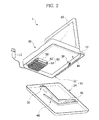
- FIG. 2 is a perspective view illustrating a connection between a heat source member and a heat dissipation unit in accordance with the embodiment of the present invention
- FIG. 3 is a sectional view schematically illustrating a portion of the natural exhaustion type ultrasonic diagnosis device in a disassembled state in accordance with the embodiment of the present invention
- FIG. 4 is a sectional view schematically illustrating a portion of the natural exhaustion type ultrasonic diagnosis device in an assembled state in accordance with the embodiment of the present invention.
- a natural exhaustion type ultrasonic diagnostic apparatus 1 in accordance with the embodiment of the present invention includes a case unit 30 forming the outer portion of a control panel 20 for ultrasonic diagnostic apparatuses, a suction part 36 provided at the lower portion of the case unit 30 and forming a path through which air is sucked into the case unit 30, and an exhaust part 38 provided at the upper portion of the case unit 30 and forming a path through which the air introduced into the case unit 30 through the suction part 36 is discharged to the outside.
- the natural exhaustion type ultrasonic diagnostic apparatus 1 in accordance with the embodiment of the present invention is used as a hand-carried ultrasound (HCU) system and is easy to carry, and the inside of the natural exhaustion type ultrasonic diagnostic apparatus 1 dissipates heat without separate power.
- HCU hand-carried ultrasound
- a probe 12 serving as ultrasonic diagnosis equipment is connected to the control panel 20, and a display 10 to display an ultrasonic image of a subject is installed at the upper portion of the control panel 20 (based on FIG. 1 ).
- the case unit 30 is installed at the outer portion of the control panel 20 for ultrasonic diagnostic apparatuses.
- the suction part 36 forming the path through which air is sucked into the case unit 30 is provided at the lower portion of the case unit 30, and the exhaust part 38 through which air is discharged to the outside of the case unit 30 is provided at the upper portion of the case unit 30.
- a handle 42 is installed at one side of the case unit 30 so as to be gripped by a user, and thus movement of the natural exhaustion type ultrasonic diagnostic apparatus 1 is more conveniently carried out.
- Air introduced into the case unit 30 through the suction part 36 is heated while cooling a heat source member 50, and is then discharged to the outside of the case unit 30 through the exhaust part 38 provided at the upper portion of the case unit 30.
- the exhaust part 38 is located above the suction part 36 so that air is naturally exhausted using upward movement of air heated while cooling the heat source member 50 due to convection, and the installed positions of the suction part 36 and the exhaust part 38 may be variously modified within such a technical conception.
- the case unit 30 in accordance with the embodiment includes a lower case 34 provided with the suction part 36, and an upper case 32 connected to the upper portion of the lower case 34 and provided with the exhaust part 38.
- An electronic unit 44 in which electronic parts are installed on a printed circuit board is installed within the upper case 32, and the heat source member 50, such as a hard disk or a central processing unit, is installed under the electronic unit 44.
- the heat source member 50 Since such a heat source member 50 contacts a channel of air introduced through the suction part 36 and moved to the exhaust part 38, the heat source member 50 may be cooled.
- a separate heat dissipation unit 60 may be installed on the heat source member 50.
- the heat dissipation unit 60 cooling the heat source member 50 through thermal conduction is formed by molding using a material exhibiting a high thermal conductivity and has a large area contacting air to achieve heat exchange with the air, the heat source member 50 may be more effectively cooled.
- the heat dissipation unit 60 in accordance with the embodiment includes a heat dissipation body 62 contacting the outer surface of the heat source member 50 and heat dissipation fins 64 protruding from the heat dissipation body 62 to increase a contact area with air.
- the heat dissipation body 62 is fixed to the outer surface of the heat source member 50 and contacts the channel of air moving from the suction part 36 to the exhaust part 38.
- a plurality of heat dissipation fins 64 is provided at the outer surface of the heat dissipation body 62, thus increasing an area contacting air to exchange heat.
- the case 30 is provided with guide diaphragms 40 guiding the channel of air moving from the suction part 36 to the exhaust part 38 to improve cooling efficiency.
- Such guide diaphragms 40 may have various shapes within a technical conception in which structures guiding the channel of air introduced into the case unit 30 through the suction part 36 and then moved to the exhaust part 38 are installed within the case unit 30.
- the guide diaphragms 40 in accordance with the embodiment protrude along both sides of the channel of air.
- the guide diaphragms 40 may connect the suction part 36 and the exhaust part 38 in a straight line, and in order to increase the velocity of air using Bernoulli's theorem to improve cooling efficiency of the heat source member 50, the guide diaphragms 40 may be configured such that the channel of air at the inside of the guide diaphragms 40 becomes narrow toward the exhaust part 38.
- the guide diaphragms 40 protrude along both sides of the channel of air, and thus guide movement of air.
- the guide diaphragms 40 in accordance with the embodiment may be formed integrally with the inner surface of the lower case 34 by molding, or may be manufactured separately and then fixed to the lower caser 34.
- an interval between the inner surfaces of the diaphragms 40 is gradually narrowed from the suction part 36 to the exhaust part 38.
- the natural exhaustion type ultrasonic diagnostic apparatus 1 in accordance with the embodiment may omit a separate fan to dissipate heat of the inside of the case unit 30 and a motor to drive the fan, and thus reduces noise generated from the inside of the case unit 30 to 20 decibels or less.
- noise generated from the inside of the case unit 30 is only operating noise generated from the hard disk drive and the central processing unit, the operating noise may be reduced and thus power consumption may be reduced.
- the heated air moves upwardly by convection, thus moving to the exhaust part 38 located above the suction part 36.
- the interval between the guide diaphragms 40 guiding the channel of the heated air is gradually narrowed from the suction part 36 to the exhaust part 38, the velocity of the air increases due to Bernoulli's theorem. Therefore, the air moving from the suction part 36 to the exhaust part 38 effectively flows and cooling efficiency of the heat source member 50 is improved.
- FIG. 5 is a sectional view schematically illustrating an inclined guide part of the natural exhaustion type ultrasonic diagnosis device in accordance with this embodiment of the present invention.
- a lower case 34 includes an inclined guide part 70 in which a bottom surface 47 is inclined toward an exhaust part 38.
- a channel of air moving between the inclined guide part 70 and an electronic unit 44 is gradually narrowed, and thus the velocity of the air toward the exhaust part 38 increases.
- the channel for the air is gradually narrowed from the suction part 36 to the exhaust part 38, the velocity of the air toward the exhaust part 38 increases due to Bernoulli's theorem, thus improving cooling efficiency of the inside of the case unit 30.
Landscapes
- Health & Medical Sciences (AREA)
- Engineering & Computer Science (AREA)
- Life Sciences & Earth Sciences (AREA)
- Physics & Mathematics (AREA)
- Pathology (AREA)
- Heart & Thoracic Surgery (AREA)
- Radar, Positioning & Navigation (AREA)
- General Physics & Mathematics (AREA)
- Biophysics (AREA)
- Nuclear Medicine, Radiotherapy & Molecular Imaging (AREA)
- Computer Networks & Wireless Communication (AREA)
- Radiology & Medical Imaging (AREA)
- Biomedical Technology (AREA)
- Remote Sensing (AREA)
- Medical Informatics (AREA)
- Molecular Biology (AREA)
- Surgery (AREA)
- Animal Behavior & Ethology (AREA)
- General Health & Medical Sciences (AREA)
- Public Health (AREA)
- Veterinary Medicine (AREA)
- Ultra Sonic Daignosis Equipment (AREA)
Abstract
A natural exhaustion type ultrasonic diagnostic apparatus. The natural exhaustion type ultrasonic diagnostic apparatus includes a case unit (30) forming the outer portion of a control panel for ultrasonic diagnostic apparatuses, a suction part (36) provided at the lower portion of the case unit and forming a path through which air is sucked into the case unit, and an exhaust part (38) provided at the upper portion of the case unit and forming a path through which the air introduced into the case unit through the suction part is discharged to the outside.
Description
- Embodiments of the present invention relate to a natural exhaustion type ultrasonic diagnostic apparatus which exhausts heated air without a separate power device to reduce noise and power consumption.
- An ultrasonic diagnostic apparatus irradiates an ultrasonic signal from the skin of the body of a subject toward a desired portion within the body, and obtains an image regarding a tomogram of soft tissue or a bloodstream using the reflected ultrasonic signal (ultrasonic echo signal).
- The ultrasonic diagnostic apparatus has a small size, is inexpensive, displays an image in real time, and does not cause X-ray exposure, as compared to an X-ray diagnostic apparatus, a computerized tomography (CT) scanner, a magnetic resonance imager (MRI) and a nuclear medicine diagnostic apparatus, thus having high safety. Therefore, the ultrasonic diagnostic apparatus is widely used for diagnoses of the heart and the abdomen, and urinary and maternity diagnoses.
- The ultrasonic diagnostic apparatus includes a probe which transmits an ultrasonic signal to a subject and receives the ultrasonic signal reflected by the subject in order to obtain an ultrasonic image of the subject.
- The probe is connected to a control panel, and thus an operating signal is transmitted from the control panel to the probe and an image measured by the probe is transmitted to the control panel.
- Since a heat source member including a hard disk drive and a central processing unit is installed within the control panel, a separate cooling device to cool the heat source member is installed.
- The above-described technical configuration is only a background to assist in understanding embodiments of the present invention, and does not mean the conventional technique is well known in the art.
- In order to dissipate heat from the inside of the control panel, a cooling fan and a motor to rotate the fan are installed, and thus operating noise and power consumption are increased. Therefore, measures to improve these negative aspects are required.
- Therefore, it is an aspect of the present invention to provide a natural exhaustion type ultrasonic diagnostic apparatus which exhausts heated air without a separate power device to reduce noise and power consumption.
- Additional aspects of the invention will be set forth in part in the description which follows and, in part, will be obvious from the description, or may be learned by practice of the invention.
- In accordance with one aspect of the present invention, a natural exhaustion type ultrasonic diagnostic apparatus includes a case unit forming the outer portion of a control panel for ultrasonic diagnostic apparatuses, a suction part provided at the lower portion of the case unit and forming a path through which air is sucked into the case unit, and an exhaust part provided at the upper portion of the case unit and forming a path through which the air introduced into the case unit through the suction part is discharged to the outside.
- The case unit may include a lower case provided with the suction part, and an upper case connected to the upper portion of the lower case and provided with the suction part.
- The case may include an inclined guide part provided with a bottom surface inclined toward the exhaust part.
- The case unit may include guide diaphragms to guide a channel of air introduced into the guide unit through the suction part and moved to the exhaust part.
- The guide diaphragms may protrude along both sides of the channel of air.
- The channel of air formed at the inside of the guide diaphragms may be gradually narrowed toward the exhaust part.
- A heat source member may contact a channel of air introduced into the guide unit through the suction part and moved to the exhaust part.
- The natural exhaustion type ultrasonic diagnostic apparatus may further include a heat dissipation unit to cool the heat source member by thermal conduction.
- The heat dissipation unit may include a heat dissipation body contacting the outer surface of the heat source member, and heat dissipation fins protruding from the heat dissipation body to increase a contact area with air.
- Noise generated from the inside of the case unit may be 20 decibels or less.
- These and/or other aspects of the invention will become apparent and more readily appreciated from the following description of the embodiments, taken in conjunction with the accompanying drawings of which:
-
FIG. 1 is an exploded perspective view schematically illustrating a portion of a natural exhaustion type ultrasonic diagnosis device in accordance with one embodiment of the present invention; -
FIG. 2 is a perspective view illustrating a connection between a heat source member and a heat dissipation unit in accordance with the embodiment of the present invention; -
FIG. 3 is a sectional view schematically illustrating a portion of the natural exhaustion type ultrasonic diagnosis device in a disassembled state in accordance with the embodiment of the present invention; -
FIG. 4 is a sectional view schematically illustrating a portion of the natural exhaustion type ultrasonic diagnosis device in an assembled state in accordance with the embodiment of the present invention; and -
FIG. 5 is a sectional view schematically illustrating an inclined guide part of a natural exhaustion type ultrasonic diagnosis device in accordance with another embodiment of the present invention. - Reference will now be made in detail to exemplary embodiments of the present invention, examples of which are illustrated in the accompanying drawings, wherein like reference numerals refer to like elements throughout.
- Hereinafter, a natural exhaustion type ultrasonic diagnosis device in accordance with one embodiment of the present invention will be described with reference to the accompanying drawings. For convenience of description, a natural exhaustion type ultrasonic diagnosis device used as a hand-carried ultrasound (HCU) system will be exemplarily illustrated. Thicknesses of lines and sizes of components shown in the drawings may be exaggerated for precision and convenience of description. Also, the terms used in the following description are terms defined taking into consideration the functions obtained in the description and may be changed in accordance with the intention of an operator or a usual practice. Therefore, the definitions of these terms should be determined based on the whole content of this specification.
-
FIG. 1 is an exploded perspective view schematically illustrating a portion of a natural exhaustion type ultrasonic diagnosis device in accordance with one embodiment of the present invention,FIG. 2 is a perspective view illustrating a connection between a heat source member and a heat dissipation unit in accordance with the embodiment of the present invention,FIG. 3 is a sectional view schematically illustrating a portion of the natural exhaustion type ultrasonic diagnosis device in a disassembled state in accordance with the embodiment of the present invention, andFIG. 4 is a sectional view schematically illustrating a portion of the natural exhaustion type ultrasonic diagnosis device in an assembled state in accordance with the embodiment of the present invention. - As shown in
FIGS. 1 to 4 , a natural exhaustion type ultrasonicdiagnostic apparatus 1 in accordance with the embodiment of the present invention includes acase unit 30 forming the outer portion of acontrol panel 20 for ultrasonic diagnostic apparatuses, asuction part 36 provided at the lower portion of thecase unit 30 and forming a path through which air is sucked into thecase unit 30, and anexhaust part 38 provided at the upper portion of thecase unit 30 and forming a path through which the air introduced into thecase unit 30 through thesuction part 36 is discharged to the outside. - The natural exhaustion type ultrasonic
diagnostic apparatus 1 in accordance with the embodiment of the present invention is used as a hand-carried ultrasound (HCU) system and is easy to carry, and the inside of the natural exhaustion type ultrasonicdiagnostic apparatus 1 dissipates heat without separate power. - A
probe 12 serving as ultrasonic diagnosis equipment is connected to thecontrol panel 20, and adisplay 10 to display an ultrasonic image of a subject is installed at the upper portion of the control panel 20 (based onFIG. 1 ). - The
case unit 30 is installed at the outer portion of thecontrol panel 20 for ultrasonic diagnostic apparatuses. Thesuction part 36 forming the path through which air is sucked into thecase unit 30 is provided at the lower portion of thecase unit 30, and theexhaust part 38 through which air is discharged to the outside of thecase unit 30 is provided at the upper portion of thecase unit 30. - A
handle 42 is installed at one side of thecase unit 30 so as to be gripped by a user, and thus movement of the natural exhaustion type ultrasonicdiagnostic apparatus 1 is more conveniently carried out. - Air introduced into the
case unit 30 through thesuction part 36 is heated while cooling aheat source member 50, and is then discharged to the outside of thecase unit 30 through theexhaust part 38 provided at the upper portion of thecase unit 30. - The
exhaust part 38 is located above thesuction part 36 so that air is naturally exhausted using upward movement of air heated while cooling theheat source member 50 due to convection, and the installed positions of thesuction part 36 and theexhaust part 38 may be variously modified within such a technical conception. - The
case unit 30 in accordance with the embodiment includes alower case 34 provided with thesuction part 36, and anupper case 32 connected to the upper portion of thelower case 34 and provided with theexhaust part 38. - An
electronic unit 44 in which electronic parts are installed on a printed circuit board is installed within theupper case 32, and theheat source member 50, such as a hard disk or a central processing unit, is installed under theelectronic unit 44. - Since such a
heat source member 50 contacts a channel of air introduced through thesuction part 36 and moved to theexhaust part 38, theheat source member 50 may be cooled. - In order to improve cooling efficiency of the
heat source member 50, a separateheat dissipation unit 60 may be installed on theheat source member 50. - Since the
heat dissipation unit 60 cooling theheat source member 50 through thermal conduction is formed by molding using a material exhibiting a high thermal conductivity and has a large area contacting air to achieve heat exchange with the air, theheat source member 50 may be more effectively cooled. - The
heat dissipation unit 60 in accordance with the embodiment includes aheat dissipation body 62 contacting the outer surface of theheat source member 50 and heat dissipation fins 64 protruding from theheat dissipation body 62 to increase a contact area with air. - The
heat dissipation body 62 is fixed to the outer surface of theheat source member 50 and contacts the channel of air moving from thesuction part 36 to theexhaust part 38. - A plurality of
heat dissipation fins 64 is provided at the outer surface of theheat dissipation body 62, thus increasing an area contacting air to exchange heat. - The
case 30 is provided withguide diaphragms 40 guiding the channel of air moving from thesuction part 36 to theexhaust part 38 to improve cooling efficiency. -
Such guide diaphragms 40 may have various shapes within a technical conception in which structures guiding the channel of air introduced into thecase unit 30 through thesuction part 36 and then moved to theexhaust part 38 are installed within thecase unit 30. - The
guide diaphragms 40 in accordance with the embodiment protrude along both sides of the channel of air. - The
guide diaphragms 40 may connect thesuction part 36 and theexhaust part 38 in a straight line, and in order to increase the velocity of air using Bernoulli's theorem to improve cooling efficiency of theheat source member 50, theguide diaphragms 40 may be configured such that the channel of air at the inside of theguide diaphragms 40 becomes narrow toward theexhaust part 38. - The
guide diaphragms 40 protrude along both sides of the channel of air, and thus guide movement of air. - The
guide diaphragms 40 in accordance with the embodiment may be formed integrally with the inner surface of thelower case 34 by molding, or may be manufactured separately and then fixed to thelower caser 34. - In order to gradually narrow the channel of air moving along the
guide diaphragms 40 to increase the velocity of air, an interval between the inner surfaces of thediaphragms 40 is gradually narrowed from thesuction part 36 to theexhaust part 38. - That is, since the interval between the inner surfaces of the portions of the
diaphragms 40 connected to thesuction part 36 is wide and the interval between the inner surfaces of the portions of thediaphragms 40 connected to theexhaust part 38 is narrow, the velocity of air moving from thesuction part 36 to theexhaust part 38 along abottom surface 46 of thelower case 34 and the inner surfaces of theguide diaphragms 40 is gradually increased, and thus natural exhaustion of the air is effectively carried out. - The natural exhaustion type ultrasonic
diagnostic apparatus 1 in accordance with the embodiment may omit a separate fan to dissipate heat of the inside of thecase unit 30 and a motor to drive the fan, and thus reduces noise generated from the inside of thecase unit 30 to 20 decibels or less. - That is, since noise generated from the inside of the
case unit 30 is only operating noise generated from the hard disk drive and the central processing unit, the operating noise may be reduced and thus power consumption may be reduced. - Hereinafter, an operating state of the natural exhaustion type ultrasonic
diagnostic apparatus 1 in accordance with the embodiment of the present invention will be described in detail with reference to the accompanying drawings. - Air introduced into the
case unit 30 through thesuction part 36 exchanges heat while contacting theheat dissipation fins 64 installed at the outside of theheat source member 50, and thereby, the air is heated and theheat source member 50 is cooled. - The heated air moves upwardly by convection, thus moving to the
exhaust part 38 located above thesuction part 36. - Further, since the interval between the
guide diaphragms 40 guiding the channel of the heated air is gradually narrowed from thesuction part 36 to theexhaust part 38, the velocity of the air increases due to Bernoulli's theorem. Therefore, the air moving from thesuction part 36 to theexhaust part 38 effectively flows and cooling efficiency of theheat source member 50 is improved. - Hereinafter, a natural exhaustion type ultrasonic
diagnostic apparatus 1 in accordance with another embodiment of the present invention will be described with reference toFIG. 5 . -
FIG. 5 is a sectional view schematically illustrating an inclined guide part of the natural exhaustion type ultrasonic diagnosis device in accordance with this embodiment of the present invention. - As shown in
FIG. 5 , alower case 34 includes aninclined guide part 70 in which abottom surface 47 is inclined toward anexhaust part 38. Thereby, a channel of air moving between theinclined guide part 70 and anelectronic unit 44 is gradually narrowed, and thus the velocity of the air toward theexhaust part 38 increases. - That is, since the
bottom surface 47 of thelower case 34 adjacent to theexhaust part 38 is upwardly inclined toward the exhaust part 38 (based onFIG. 5 ) and a moving area of air moving along the inner surfaces ofguide diaphragms 41 installed along theinclined guide part 70 is narrowed, the velocity of the air increases due to Bernoulli's theorem and thus cooling efficiency of theheat source member 50 is improved. - In the natural exhaustion type ultrasonic diagnostic apparatus having the above-described configuration in accordance with this embodiment, since the
exhaust part 38 is located at a position higher than thesuction part 36, heated air is naturally exhausted to the outside using convection of air, thereby reducing operating noise and power consumption. - Further, since the channel for the air is gradually narrowed from the
suction part 36 to theexhaust part 38, the velocity of the air toward theexhaust part 38 increases due to Bernoulli's theorem, thus improving cooling efficiency of the inside of thecase unit 30. - Although a few embodiments of the present invention have been shown and described, it would be appreciated by those skilled in the art that changes may be made in these embodiments without departing from the principles and spirit of the invention, the scope of which is defined in the claims and their equivalents.
- That is, although a natural exhaustion type ultrasonic diagnostic apparatus used as a hand-carried ultrasound (HCU) system has been exemplarily illustrated, the natural exhaustion type ultrasonic diagnostic apparatus in accordance with [[one]] an embodiment of the present invention may be applied to other apparatuses requiring dissipation of heat from the insides thereof.
Claims (10)
- A natural exhaustion type ultrasonic diagnostic apparatus comprising:a case unit forming an outer portion of a control panel for ultrasonic diagnostic apparatuses;a suction part provided at a lower portion of the case unit and forming a path through which air is sucked into the case unit; andan exhaust part provided at an upper portion of the case unit and forming a path through which the air introduced into the case unit through the suction part is discharged to outside the case unit.
- The natural exhaustion type ultrasonic diagnostic apparatus according to claim 1, wherein the case unit includes:a lower case provided with the suction part; andan upper case connected to an upper portion of the lower case and provided with the exhaust part.
- The natural exhaustion type ultrasonic diagnostic apparatus according to claim 2, wherein the lower case includes an inclined guide part provided with a bottom surface inclined toward the exhaust part.
- The natural exhaustion type ultrasonic diagnostic apparatus according to claim 1, wherein the case unit includes guide diaphragms to guide a channel of air introduced into the case unit through the suction part and moved to the exhaust part.
- The natural exhaustion type ultrasonic diagnostic apparatus according to claim 4, wherein the guide diaphragms protrude along both sides of the channel of air.
- The natural exhaustion type ultrasonic diagnostic apparatus according to claim 5, wherein the channel of air formed between the guide diaphragms is gradually narrowed toward the exhaust part.
- The natural exhaustion type ultrasonic diagnostic apparatus according to claim 1, wherein a heat source member contacts a channel of air introduced into the case unit through the suction part and moved to the exhaust part.
- The natural exhaustion type ultrasonic diagnostic apparatus according to claim 7, further comprising a heat dissipation unit to cool the heat source member by thermal conduction.
- The natural exhaustion type ultrasonic diagnostic apparatus according to claim 8, wherein the heat dissipation unit includes:a heat dissipation body contacting an outer surface of the heat source member; andheat dissipation fins protruding from the heat dissipation body to increase a contact area with air.
- The natural exhaustion type ultrasonic diagnostic apparatus according to claim 7, wherein noise generated from inside the case unit is 20 decibels or less.
Applications Claiming Priority (2)
| Application Number | Priority Date | Filing Date | Title |
|---|---|---|---|
| KR1020110014743A KR20120095214A (en) | 2011-02-18 | 2011-02-18 | Natural exhaustion type ultrasonic diagnosis apparatus |
| KR1020110014744A KR20120095215A (en) | 2011-02-18 | 2011-02-18 | Natural exhaustion type ultrasonic diagnosis apparatus |
Publications (1)
| Publication Number | Publication Date |
|---|---|
| EP2490098A1 true EP2490098A1 (en) | 2012-08-22 |
Family
ID=45540822
Family Applications (1)
| Application Number | Title | Priority Date | Filing Date |
|---|---|---|---|
| EP12152798A Withdrawn EP2490098A1 (en) | 2011-02-18 | 2012-01-27 | Natural exhaustion type ultrasonic diagnostic apparatus |
Country Status (2)
| Country | Link |
|---|---|
| US (1) | US20120215111A1 (en) |
| EP (1) | EP2490098A1 (en) |
Families Citing this family (1)
| Publication number | Priority date | Publication date | Assignee | Title |
|---|---|---|---|---|
| KR20170014395A (en) * | 2015-07-30 | 2017-02-08 | 삼성메디슨 주식회사 | Medical imaging device |
Citations (3)
| Publication number | Priority date | Publication date | Assignee | Title |
|---|---|---|---|---|
| US6577502B1 (en) * | 2000-06-28 | 2003-06-10 | Intel Corporation | Mobile computer having a housing with openings for cooling |
| US20080089023A1 (en) * | 2006-10-11 | 2008-04-17 | David Bruce Kumhyr | Venturi bernoulli heat extraction system for laptop computers |
| US20090153548A1 (en) * | 2007-11-12 | 2009-06-18 | Stein Inge Rabben | Method and system for slice alignment in diagnostic imaging systems |
Family Cites Families (1)
| Publication number | Priority date | Publication date | Assignee | Title |
|---|---|---|---|---|
| US6601390B1 (en) * | 2002-02-05 | 2003-08-05 | Sony Corporation | Method and apparatus for converting dissipated heat to work energy |
-
2012
- 2012-01-20 US US13/355,236 patent/US20120215111A1/en not_active Abandoned
- 2012-01-27 EP EP12152798A patent/EP2490098A1/en not_active Withdrawn
Patent Citations (3)
| Publication number | Priority date | Publication date | Assignee | Title |
|---|---|---|---|---|
| US6577502B1 (en) * | 2000-06-28 | 2003-06-10 | Intel Corporation | Mobile computer having a housing with openings for cooling |
| US20080089023A1 (en) * | 2006-10-11 | 2008-04-17 | David Bruce Kumhyr | Venturi bernoulli heat extraction system for laptop computers |
| US20090153548A1 (en) * | 2007-11-12 | 2009-06-18 | Stein Inge Rabben | Method and system for slice alignment in diagnostic imaging systems |
Non-Patent Citations (1)
| Title |
|---|
| SUZUKI M ET AL: "FAN-LESS COOLING TECHNOLOGY FOR NOTEBOOK COMPUTERS", FUJITSU-SCIENTIFIC AND TECHNICAL JOURNAL, FUJITSU LTD, JP, vol. 34, no. 1, 1 September 1998 (1998-09-01), pages 87 - 95, XP000859889, ISSN: 0016-2523 * |
Also Published As
| Publication number | Publication date |
|---|---|
| US20120215111A1 (en) | 2012-08-23 |
Similar Documents
| Publication | Publication Date | Title |
|---|---|---|
| US11484289B2 (en) | Probe for ultrasonic diagnostic apparatus | |
| CN103533896B (en) | There is the matrix ultrasonic probe that passive heat dissipates | |
| CN106232014A (en) | Radiator structure for portable ultrasonic diagnostic equipment | |
| US20100331702A1 (en) | Ultrasonic probe and ultrasonic diagnostic apparatus | |
| CN105078510B (en) | The device of the connector of ultrasonic probe can be connected | |
| JP5608008B2 (en) | Probe for ultrasonic diagnostic apparatus and control method thereof | |
| US10117642B2 (en) | Ultrasound transducer with sealed, active cooling | |
| CN101273906B (en) | medical device | |
| TWI565451B (en) | Thin medical positioning device | |
| US20180014813A1 (en) | Ultrasound transducer probe with heat transfer device | |
| CN101809459B (en) | Systems and methods for mechanical translation of full matrix arrays | |
| EP2878269A1 (en) | Ultrasonic probe and ultrasonic imaging apparatus having the same | |
| US20120215111A1 (en) | Natural exhaustion type ultrasonic diagnostic apparatus | |
| KR100992446B1 (en) | Probe | |
| CN204147210U (en) | Sick bed X-ray magazine placement mechanism and X-ray film making sick bed | |
| KR20180056970A (en) | Cooling system for ultrasound diagnosis apparatus | |
| KR20120095214A (en) | Natural exhaustion type ultrasonic diagnosis apparatus | |
| JP4851210B2 (en) | Ultrasonic diagnostic equipment | |
| KR20120095215A (en) | Natural exhaustion type ultrasonic diagnosis apparatus | |
| KR20110097148A (en) | Fluid thermostat and probe device | |
| CN216090456U (en) | Medical clinical image diagnostic instrument | |
| KR20200098193A (en) | Ultrasonic Diagnostic Apparatus | |
| KR102660587B1 (en) | Ultrasonic probe | |
| CN201414812Y (en) | Medical ultrasonic B probe constant temperature heating equipment | |
| JP2010000220A (en) | Ultrasonic diagnostic apparatus |
Legal Events
| Date | Code | Title | Description |
|---|---|---|---|
| PUAI | Public reference made under article 153(3) epc to a published international application that has entered the european phase |
Free format text: ORIGINAL CODE: 0009012 |
|
| AK | Designated contracting states |
Kind code of ref document: A1 Designated state(s): AL AT BE BG CH CY CZ DE DK EE ES FI FR GB GR HR HU IE IS IT LI LT LU LV MC MK MT NL NO PL PT RO RS SE SI SK SM TR |
|
| AX | Request for extension of the european patent |
Extension state: BA ME |
|
| 17P | Request for examination filed |
Effective date: 20130222 |
|
| 17Q | First examination report despatched |
Effective date: 20160727 |
|
| STAA | Information on the status of an ep patent application or granted ep patent |
Free format text: STATUS: THE APPLICATION IS DEEMED TO BE WITHDRAWN |
|
| 18D | Application deemed to be withdrawn |
Effective date: 20170207 |