EP2490016A1 - Contact member for a gas sensor, gas sensor, restraint member, method for connecting a contact member with a sensor element in a gas sensor, and method for manufacturing a gas sensor - Google Patents
Contact member for a gas sensor, gas sensor, restraint member, method for connecting a contact member with a sensor element in a gas sensor, and method for manufacturing a gas sensor Download PDFInfo
- Publication number
- EP2490016A1 EP2490016A1 EP10823311A EP10823311A EP2490016A1 EP 2490016 A1 EP2490016 A1 EP 2490016A1 EP 10823311 A EP10823311 A EP 10823311A EP 10823311 A EP10823311 A EP 10823311A EP 2490016 A1 EP2490016 A1 EP 2490016A1
- Authority
- EP
- European Patent Office
- Prior art keywords
- pair
- sensor element
- housing members
- constraint
- contact
- Prior art date
- Legal status (The legal status is an assumption and is not a legal conclusion. Google has not performed a legal analysis and makes no representation as to the accuracy of the status listed.)
- Granted
Links
- 238000000034 method Methods 0.000 title claims description 15
- 238000004519 manufacturing process Methods 0.000 title claims description 9
- 238000006073 displacement reaction Methods 0.000 claims abstract description 18
- 238000006243 chemical reaction Methods 0.000 claims abstract description 11
- 238000003780 insertion Methods 0.000 claims description 22
- 230000037431 insertion Effects 0.000 claims description 22
- 230000007246 mechanism Effects 0.000 claims description 21
- 239000002184 metal Substances 0.000 description 77
- 239000007789 gas Substances 0.000 description 58
- 238000003825 pressing Methods 0.000 description 16
- MCMNRKCIXSYSNV-UHFFFAOYSA-N Zirconium dioxide Chemical compound O=[Zr]=O MCMNRKCIXSYSNV-UHFFFAOYSA-N 0.000 description 8
- 238000005259 measurement Methods 0.000 description 7
- 230000000694 effects Effects 0.000 description 6
- WABPQHHGFIMREM-UHFFFAOYSA-N lead(0) Chemical compound [Pb] WABPQHHGFIMREM-UHFFFAOYSA-N 0.000 description 6
- 239000000919 ceramic Substances 0.000 description 2
- 239000001301 oxygen Substances 0.000 description 2
- 229910052760 oxygen Inorganic materials 0.000 description 2
- 230000000717 retained effect Effects 0.000 description 2
- 230000015572 biosynthetic process Effects 0.000 description 1
- 239000000567 combustion gas Substances 0.000 description 1
- 230000007547 defect Effects 0.000 description 1
- 238000001514 detection method Methods 0.000 description 1
- 230000010354 integration Effects 0.000 description 1
- 238000010030 laminating Methods 0.000 description 1
- 230000014759 maintenance of location Effects 0.000 description 1
- 239000007784 solid electrolyte Substances 0.000 description 1
Images




Classifications
-
- G—PHYSICS
- G01—MEASURING; TESTING
- G01N—INVESTIGATING OR ANALYSING MATERIALS BY DETERMINING THEIR CHEMICAL OR PHYSICAL PROPERTIES
- G01N27/00—Investigating or analysing materials by the use of electric, electrochemical, or magnetic means
- G01N27/26—Investigating or analysing materials by the use of electric, electrochemical, or magnetic means by investigating electrochemical variables; by using electrolysis or electrophoresis
- G01N27/403—Cells and electrode assemblies
- G01N27/406—Cells and probes with solid electrolytes
- G01N27/407—Cells and probes with solid electrolytes for investigating or analysing gases
-
- G—PHYSICS
- G01—MEASURING; TESTING
- G01N—INVESTIGATING OR ANALYSING MATERIALS BY DETERMINING THEIR CHEMICAL OR PHYSICAL PROPERTIES
- G01N27/00—Investigating or analysing materials by the use of electric, electrochemical, or magnetic means
- G01N27/26—Investigating or analysing materials by the use of electric, electrochemical, or magnetic means by investigating electrochemical variables; by using electrolysis or electrophoresis
- G01N27/403—Cells and electrode assemblies
- G01N27/406—Cells and probes with solid electrolytes
- G01N27/4062—Electrical connectors associated therewith
-
- H—ELECTRICITY
- H01—ELECTRIC ELEMENTS
- H01R—ELECTRICALLY-CONDUCTIVE CONNECTIONS; STRUCTURAL ASSOCIATIONS OF A PLURALITY OF MUTUALLY-INSULATED ELECTRICAL CONNECTING ELEMENTS; COUPLING DEVICES; CURRENT COLLECTORS
- H01R11/00—Individual connecting elements providing two or more spaced connecting locations for conductive members which are, or may be, thereby interconnected, e.g. end pieces for wires or cables supported by the wire or cable and having means for facilitating electrical connection to some other wire, terminal, or conductive member, blocks of binding posts
- H01R11/11—End pieces or tapping pieces for wires, supported by the wire and for facilitating electrical connection to some other wire, terminal or conductive member
- H01R11/22—End pieces terminating in a spring clip
-
- H—ELECTRICITY
- H01—ELECTRIC ELEMENTS
- H01R—ELECTRICALLY-CONDUCTIVE CONNECTIONS; STRUCTURAL ASSOCIATIONS OF A PLURALITY OF MUTUALLY-INSULATED ELECTRICAL CONNECTING ELEMENTS; COUPLING DEVICES; CURRENT COLLECTORS
- H01R24/00—Two-part coupling devices, or either of their cooperating parts, characterised by their overall structure
- H01R24/60—Contacts spaced along planar side wall transverse to longitudinal axis of engagement
- H01R24/62—Sliding engagements with one side only, e.g. modular jack coupling devices
-
- Y—GENERAL TAGGING OF NEW TECHNOLOGICAL DEVELOPMENTS; GENERAL TAGGING OF CROSS-SECTIONAL TECHNOLOGIES SPANNING OVER SEVERAL SECTIONS OF THE IPC; TECHNICAL SUBJECTS COVERED BY FORMER USPC CROSS-REFERENCE ART COLLECTIONS [XRACs] AND DIGESTS
- Y10—TECHNICAL SUBJECTS COVERED BY FORMER USPC
- Y10T—TECHNICAL SUBJECTS COVERED BY FORMER US CLASSIFICATION
- Y10T29/00—Metal working
- Y10T29/49—Method of mechanical manufacture
- Y10T29/49826—Assembling or joining
Definitions
- the present invention relates to a gas sensor for measuring a concentration of a predetermined gas component in a measurement gas, and more particularly to a technique of retaining and fixing a sensor element thereof.
- a concentration of a desired gas component in a measurement gas there have been known various measuring apparatuses.
- an apparatus which measures an NOx concentration in the measurement gas such as a combustion gas or the like
- a gas sensor an NOx sensor
- ZrO 2 zirconia
- the sensor element of the gas sensor mentioned above typically has a plurality of electrode terminals on a surface for applying an electric voltage, picking up a detection signal, supplying an electric power to a heater part and the like.
- the gas sensor is provided with a contact member in which the sensor element is inserted so as to retain.
- a gas sensor having a contact member which is provided with a housing forming an insertion port in which the sensor element is inserted by a pair of housing members arranged so as to be opposed to each other, a plurality of contact point members which are additionally provided in the housing members and constructed by metal terminals, and a plurality of lead wires which are connected to the contact point members and achieve an electric continuity between the sensor element and an external portion (for example, refer to Japanese Utility Model Application Laid-Open No. 4-110972 (patent document 2)).
- the contact member retains the sensor element which is inserted in an insertion port, in a state that the contact point member is brought into contact with the electrode terminal, thereby obtaining the electric continuity between the sensor element and the external portion.
- the contact point member plays a role in a contact point with the electrode terminal.
- housing members are fitted into a fixing metal fixture having a C-shaped form in a cross sectional view with the pressing spring in its upper and lower sides, while the sensor element is inserted in the insertion port therebetween, and then, a caulking ring is arranged in an outer periphery of the fixing metal fixture and the pressing spring and is caulked so that the spring ring is displaced to energize the contact point member to the electrode terminal with an elastic force of the pressing spring.
- the fixing metal fixture disclosed in Japanese Utility Model Application Laid-Open No. 4-110972 not only has a role for fixing the spring member as mentioned above, but also has a role for constraining a pair of housing members in a predetermined arrangement relationship as long as the sensor element is inserted and the caulking ring is caulked.
- the constraint mentioned above is necessary for correctly bringing the electrode terminal with the corresponding contact point member without any displacement, at a time of retaining and fixing the sensor element to the contact member between a pair of housing members (that is, in the insertion port) by caulking the caulking ring.
- Japanese Utility Mode Application Laid-Open No. 4-110972 by forming the fixing metal fixture in the C-shaped form in the cross section, its elasticity as a leaf spring is utilized for retaining and constraining the housing member.
- the elastic force of the pressing spring acts on the housing via the fixing metal fixture with the caulking ring being caulked, whereby the sensor element is fixed to the housing.
- the contact point member provided in the housing energizes the electrode terminal, whereby a contact between the electrode terminal and the contact point member is secured.
- the present invention is made by taking the problem mentioned above into consideration, and an object of the present invention is to provide a gas sensor which can stably carry out a securement of an electric continuity between a sensor element and a contact member.
- a first aspect of the present invention provides a contact member for a gas sensor in which an electric connection to a sensor element is obtained by pinching and fixing the sensor element in an inserting port formed by a pair of housing members, including: a constraint member which is provided in an outer periphery of the pair of housing members and has a constraining function of constraining a displacement of the pair of housing members within a predetermined range; and an annular member which is provided in an outer periphery of the constraint member, wherein the pair of housing members and the sensor element are brought into pressure contact, and the sensor element is pinched and fixed by the pair of housing members in a state that an electrode terminal provided in the sensor element comes into contact with a contact point member provided in the pair of housing members, due to contractive deformation of the annular member with receiving an external force in a state that the sensor element is inserted in the insertion port, and the constraint member constrains a displacement of the pair of housing members within a predetermined range before the sensor element is pinched and
- the constraint member is constructed by a first member and a second member, and the engagement of the first member and the second member causes the constraint of the pair of housing members with the constraint member.
- the constraint member is provided with two sets of engaging mechanisms which engage the first member and the second member, and each of the two sets of engaging mechanisms is constructed by an engaging part which is provided in one of the first member and the second member and an engaged part which is provided in the other.
- each of the first member and the second member is provided with the engaging part and the engaged part of the two sets of engaging mechanisms one by one.
- the first member and the second member are members having approximately the same shape.
- the engaging parts of both of the two sets of engaging mechanisms are provided in one of the first member and the second member, and the engaged parts of both of the two sets of engaging mechanisms are provided in the other of the first member and the second member.
- a seventh aspect of the present invention provides a gas sensor including: a sensor element; and the contact member for the gas sensor according to any one of the first to sixth aspects.
- An eighth aspect of the present invention provides a constraint member used in the contact member for the gas sensor according to any one of the first to sixth aspects.
- a ninth aspect of the present invention provides a connecting method of a sensor element of a gas sensor and a contact member, including: a step of preparing a contact member that includes a pair of housing members which are arranged to form an insertion port in which the sensor element is inserted, a constraint member which is provided in an outer periphery of the pair of housing members, and has a constraining function of constraining a displacement of the pair of housing members within a predetermined range, and an annular member which is provided in an outer periphery of the constraint member; a step of inserting the sensor element in the insertion port; and a step of bringing the pair of housing members into pressure contact with the sensor element by applying an external force to the annular member to deform the annular member so as to contract, thereby pinching and fixing the sensor element in the pair of housing members in a state that an electrode terminal provided in the sensor element is brought into contact with a contact point member provided in the pair of housing members, wherein the constraint member constrains a displacement of the pair of housing
- the constraint member is constructed by a first member and a second member, and the engagement of the first member and the second member causes the constraint of the pair of housing members with the constraint member.
- the constraint member is provided with two sets of engaging mechanisms which engage the first member and the second member, and each of the two sets of engaging mechanisms is constructed by an engaging part which is provided in one of the first member and the second member and an engaged part which is provided in the other.
- a twelfth aspect of the present invention provides a manufacturing method of a gas sensor including: a step of arranging a pair of housing members in a state of forming an inserting port in which a sensor element is inserted; a step of providing a constraint member having a constraining function of constraining a displacement of the pair of housing members within a predetermined range, in an outer periphery of the pair of housing members; a step of providing an annular member in an outer periphery of the constraint member; a step of inserting the sensor element in the insertion port; and a step of bringing the pair of housing members into pressure contact with the sensor element by applying an external force to the annular member to deform the annular member so as to contract, thereby pinching and fixing the sensor element in the pair of housing members in a state that an electrode terminal provided in the sensor element is brought into contact with a contact point member provided in the pair of housing members, wherein the constraint member constrains a displacement of the pair of housing members within a predetermined range before the
- the constraint member is constructed by a first member and a second member, and the engagement of the first member and the second member causes the constraint of the pair of housing members with the constraint member.
- the constraint member is provided with two sets of engaging mechanisms which engage the first member and the second member, and each of the two sets of engaging mechanisms is constructed by an engaging part which is provided in one of the first member and the second member and an engaged part which is provided in the other.
- a fifteenth aspect of the present invention provides a gas sensor manufactured by the manufacturing method of the gas sensor according to any one of the twelfth to fourteenth aspects.
- the gas sensor 100 is structured such as to detect a predetermined gas component (a target gas component) in a gas that is a measuring target (a measurement gas), and measure a concentration thereof.
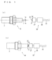
- Fig. 1 is a view showing a situation at a time of assembling the gas sensor 100.
- Fig. 1(a) shows a situation before the assembling
- Fig. 1(b) shows a situation after the assembling.
- the gas sensor 100 has a structure in which a gas sensor main body 10 and a contact member 20 are integrated.
- the gas sensor main body 10 is provided with a sensor element 1 which is a gas detector, and an accommodating member 2 which accommodates the sensor element 1.
- the contact member 20 is mainly provided with a plurality of contact point members 21, a lead wire 22 which is connected to the contact point members 21, a housing which is made of a ceramic and where the sensor element 1 is fitted in its insertion port 23 via the contact point members 21 so as to retain, and a grommet 28 which is formed in such a manner that the lead wire 22 can be inserted inside thereof in an airtight manner.
- the sensor element 1 provided in the gas sensor main body 10 is inserted to the insertion port 23 of the housing 24 provided in the contact member 20, and the sensor element 1 is retained in the housing 24 via the contact point members 21, whereby the gas sensor 100 is integrated.
- Fig. 2 is a perspective view showing an outer shape of the sensor element 1.
- the sensor element 1 has a structure in which a plurality of layers are laminated, each of which is constructed by an oxygen ion conducting solid electrolyte such as a zirconia (ZrO 2 ) or the like. Further, front and back surfaces of the sensor element 1 are provided with a plurality of electrode terminals 1a for applying an electric voltage, picking up a detected signal, supplying an electric power to a heater part and the like.
- ZrO 2 zirconia
- the sensor element 1 in which four electrode terminals 1a are provided in one surface (an illustration of the electrode terminals 1a in the back surface side is omitted), however, this is just an exemplification, and the number of the electrode terminals 1a can be appropriately determined in accordance with the structure of the sensor element 1.
- the sensor element 1 has a gas introduction port 3 introducing a reference gas in an end surface 1s in a side where the electrode terminal 1a is provided, and is provided with a measurement gas introduction port which is not illustrated, in another end portion.
- the sensor element 1 is manufactured, for example, by carrying out following steps: performing a predetermined processing and printing electrodes and wiring patterns on ceramics green sheets each corresponding to each of the layers of the sensor element 1, thereafter laminating them and cut in a predetermined magnitude, and burning the obtained laminated body.
- the target gas component is detected by utilizing a matter that an electric current corresponding to an abundance of the target gas component in the measurement gas flows between the predetermined electrodes provided inside at a time when the measurement gas is introduced to the sensor element 1.
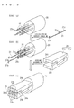
- Fig. 3 and Fig. 4 are views schematically showing the assembling process of the contact member 20.
- the assembling process of the contact member 20 is called as “preliminary assembling process”, and the assembly is called as “preliminary assembly”.
- a state (a) in Fig. 3 the lead wire 22 is inserted to the grommet 28.
- a state (b) a crimp part 21a of the contact point member 21 is connected to an end part 22a of the lead wire 22.
- the connection is achieved by caulking the contact part 21a from its outer side with the end part 22a of the lead wire 22 pinched to the crimp part 21a.
- a state (b) there is exemplified a case that the contact point members 21 are connected only to two lead wires 22 for simplifying an illustration, however, the contact point members 21 are practically connected to all the lead wires 22.
- the housing 24 is next assembled as shown as a state (c).
- the housing 24 is constructed by a pair of housing members 24a which are arranged so as to be opposed to each other, and a first attaching part 21b and a second attaching part 21c provided in the respective contact point members 21 are attached to predetermined positions of the housing member 24a, whereby an assembly of the housing 24 is achieved.
- the first attaching part 21b is attached to a first attached part 241 which is provided in one end part of the housing member 24a. Accordingly, the shapes of the first attaching part 21b and the first attached part 241 are defined in a manner that such attaching state can be well maintained. That is, the first attaching part 21b is processed to have a shape which is along a side cross sectional shape of the first attached part 241.
- the second attaching part 21c is attached to the housing member 24a by being inserted and fitted to a second attached part (not shown) provided in a center part of the housing member 24a.
- the respective housing members 24a have approximately the same cross sectional shape, at a time of assembling, and are set to a mutually spaced state so that a space having a rectangular shape in a cross sectional view serving as the insertion port 23 is formed between both the members.
- gaps 24b are provided in end parts of two housing members 24a.
- the housing member 24a can be said to have such a shape that the housing having a space inside and formed as a rectangular shape in a cross sectional view is divided into two pieces.
- a fixing metal fixture 25 to which a pressing spring 26 is previously fixed is assembled in an outer side of the housing 24 concurrently.
- the pressing spring 26 is a leaf spring member which is formed as a trapezoidal shape without an upper base part in a cross sectional view, and generates an elastic force if an external force acts on a free end part 261 thereof, as its restoring force.
- the fixing metal fixture 25 has a role for fixing the pressing spring 26, and has a role for maintaining an assembled state of the housing 24, more particularly, a state in which the insertion port 23 is formed, while the sensor element 1 is pinched and fixed.
- the fixing metal fixture 25 is a constraint member which constrains a pair of housing members 24a within a predetermined arrangement range so that the formation of the insertion port 23 is kept.
- the gas sensor 100 according to the present embodiment is characterized in that the fixing metal fixture 25 is constructed by combining a first fixture member 25a and a second fixture member 25b. Details of the fixing metal fixture 25 will be mentioned later.
- a caulking member 27 which is an annular (a cylindrical) member is assembled, as shown as a state (e).
- the preliminary assembly is finished.
- the state (e) shows a state after the contact member 20 is assembled.
- the caulking ring 27 is caulked in a state that the sensor element 1 is inserted in the insertion port 23 of the housing 24 at a time of integrating the gas sensor main body 10 and the contact member 20, after the preliminary assembly. In other words, the caulking ring 27 is deformed to shrink by an external force. In accordance with this, a clearance of the insertion port 23 of the housing 24 is narrowed, and the sensor element 1 is energized from two of upper and lower directions by the contact point member 21 provided in each of the housing members 24a. In other words, a state that the sensor element 1 is pinched and fixed by a pair of housing members 24a is achieved. At this time, since each of the contact point members 21 comes into contact with the corresponding electrode terminal 1a, an electric continuity between the sensor element 1 and the exterior is achieved via the lead wire 22 which is connected to the contact point member 21.
- the present embodiment is characterized in that the fixing metal fixture 25 is constructed by a combination of the first fixture member 25a and the second fixture member 25b.
- a description will be given below of an operation and effect by employing the structure mentioned above, in addition to a specific description of the structure of the fixing metal fixture 25.
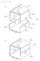
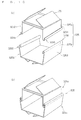
- Fig. 5 is a perspective view showing a structure of the fixing metal fixture 25.
- Fig. 5(a) shows a state before assembling the first fixture member 25a and the second fixture member 25b
- Fig. 5(b) shows a state in which the first fixture member 25a and the second fixture member 25b are assembled.
- the first fixture member 25a and the second fixture member 25b are the members having the same shape of approximately C-shaped form in a cross sectional view.
- the first fixture member 25a and the second fixture member 25b have a structure in which a first side surface part 251 and a second side surface part 252 opposed to each other are connected vertically to an upper surface part 253.
- each of side surface parts of the first fixture member 25a and the second fixture member 25b is formed in such a manner as to be deformable in an elastic range having a line of intersection with the upper surface part 253 as an axis.
- the first side surface part 251 is provided with an engaging part 254.
- the engaging part 254 is a protruding part which is provided in such a manner that a cut part of the C-shaped form is bent toward an outer side of the first side surface part 251 while having an end part side of the first side surface part 251 as a supporting point, so as to form an angle of about several degrees to the maximum with respect to the first side surface part 251.
- the second side surface part 252 is provided with an engaged part 255 which is a rectangular opening part with which the engaging part 254 can engage.
- a set of the engaging part 254 in one of the first fixture member 25a and the second fixture member 25b and the engaged part 255 of another of them form one engaging mechanism. That is, this can be said that the fixing metal fixture 25 have two sets of engaging mechanisms (a pair of engaging mechanism pairs).
- the upper surface part 253 is structured such that the pressing spring 26 is retained by a pair of retaining part 256 (in this case, only a part of which is illustrated in Fig. 5 ).
- the upper surface part 253 is previously provided with an extending part which extends from itself at its end part, and a lower base part of the pressing spring 26 is pinched between the upper surface part 253 and the extending part by folding back the extending part, thereby retaining the pressing spring 26.
- a retaining aspect of the pressing spring 26 by the fixing metal fixture 25 is not limited to this.
- the fixing metal fixture 25 in which the first fixture member 25a and the second fixture member 25b are combined as shown in Fig. 5(b) is constructed.
- each of the side surface parts of the first fixture member 25a and the second fixture member 25b is formed so as to be elastically deformable, the engagement can be easily achieved.
- the assembly of the fixing metal fixture 25 shown in the state (d) in Fig. 4 is achieved by carrying out an engagement shown in Fig. 5(b) in a state that the housing 24 is arranged therebetween. In other words, it can be said that the fixing metal fixture 25 functions as a constraint member constraining the housing member 24a owing to this engaged state.
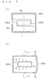
- Fig. 6 is a view schematically showing a state of the fixing metal fixture 25 before and after, in the case that the caulking ring 27 is caulked for integrating the gas sensor main body 10 and the contact member 20.
- the contact point member 21, the pressing spring 26 and the caulking ring 27 are omitted.
- Fig. 6(a) is a cross sectional view of the contact member 20 showing a state before the caulking ring 27 is caulked
- Fig. 6(b) is a cross sectional view of the contact member 20 showing a state after the caulking ring 27 is caulked.
- Figs. 6(c) and (d) are partly enlarged views of the fixing metal fixture 25 in the respective cases.
- the fixing metal fixture 25 functions as a constraint member, and constrains the housing member 24a and the second element 1, however, the housing member 24a and the sensor element 1 are not completely fixed, but can displace within a certain range.
- the contact point member attached to the housing member 24a comes into contact with the sensor element 1, and the sensor element 1 is pinched and fixed by a pair of housing members 24a in such a manner that the elastic force F1 mentioned above goes with a drag F2 acting as a reaction force of the elastic force which the sensor element 1 receives from the contact point member 21 (accurately, a sum of the drags F2 from the individual contact point members 21).
- each of the first fixture member 25a and the second fixture member 25b displaces at ⁇ z, however, in the fixing metal fixture 25, as shown in Fig. 6(d) , the engagement of the engaging part 254 of each of the first fixture member 25a and the second fixture member 25b with respect to the engaged part 255 of the other is released, in accordance with the displacement mentioned above.
- the first fixture member 25a and the second fixture member 25b turns to a non-engaged state so as to be simply pinched by the pressing spring 26 and the housing member 24a.
- the elastic force F1 from the pressing spring 26 is directly applied to the housing member 24a regardless of the constraint by the fixing metal fixture 25.
- Fig. 7 is a view schematically showing a state of a conventional fixing metal fixture 1025 having a C-shaped form in a cross section in use before and after caulking the caulking ring 27 for comparison.
- the fixing metal fixture 1025 is structured such that a gap 1025a is formed by making one side open, however, a side opposing to the gap 1025a is a fixed end 1025b.
- the housing member 24a and the sensor element 1 are constrained by the fixing metal fixture 1025, however, the housing member 24a and the sensor element 1 can displace in a certain range.
- the gap 1025a becomes smaller in the fixing metal fixture 1025, and a deformation is generated in the side of the fixing end 1025b, as shown in Fig. 7(b) .
- the elastic force which the sensor element 1 receives from the contact point member 21 and the drag F2 thereof become non-uniform which are different in the individual contact point members 21, and a reaction force F3 with respect to the deformation is generated in the fixing metal fixture 1025 itself. Accordingly, the contact state between the contact point member 21 and the electrode terminal 1a of the sensor element 1 does not become uniform. In some cases, contact point defect is generated.
- the fixing metal fixture 25 constrains the housing member 24a and the sensor element 1 before caulking as mentioned above, it does not generate any reaction force at a time of caulking. This is why a non-uniformity depending on the location is not occurred in the contact state between the contact point member 21 and the electrode terminal 1a of the sensor element 1. That is, a stable contact state can be securely achieved by using the fixing metal fixture 25 in accordance with the present embodiment.
- the fixing metal fixture 25 by the first fixture member 25a and the second fixture member 25b having such the structure that they can be engaged with each other before being caulked but their the engagement is released after caulking.
- Fig. 8 , Fig. 9 and Fig. 10 are perspective views schematically showing structures of fixing metal fixtures in accordance with various modified embodiments.
- (a) shows a non-engaged state
- (b) shows an engaged state.
- All of the fixing metal fixtures shown in Fig. 8 , Fig. 9 and Fig. 10 are in common with the embodiment mentioned above, in that each of them is constructed by the first fixture member and the second fixture member which have approximately the C-shaped form in the cross sectional view.
- the fixing metal fixture 125 shown in Fig. 8 is structured such that the same engaging part 254 as the embodiment mentioned above is provided in both of a first side surface part 1251 and a second side surface part 1252 of the first fixture member 125a, and the same engaged part 255 as the embodiment mentioned above is provided in both of a first side surface part 1253 and a second side surface part 1254 of the second fixture member 125b, in accordance with the engaging part 254 in each of the first fixture members 1251a.
- the fixing metal fixture 125 is different from the fixing metal fixture 25 in that the first fixture member 125a and the second fixture member 125b have the different shapes, whereas two fixture members have the same shape in the fixing metal fixture 25.
- the fixing metal fixture 125 having the structure mentioned above is the same as the fixing metal fixture 25 in that the engaged state is established by engaging the engaging part 254 in each of the first fixture members 1251a with the corresponding engaged part 255 in the second fixture member 125b, and the non-engaged state is established by releasing the engagement by the application of the force compressing in the vertical direction. Accordingly, in the case that the fixing metal fixture 125 mentioned above is used for the preliminary assembly of the contact member 20, it is possible to obtain the same operation and effect as the case of using the fixing metal fixture 25.
- a fixing metal fixture 225 shown in Fig. 9 is structured such that an engaging part 2255 formed as a semispherical shape is provided in both of a first side surface part 2251 and a second side surface part 2252 of a first fixture member 225a, and a circular engaged part 2256 is provided in both of a first side surface part 2253 and a second side surface part 2254 of a second fixture member 225b in accordance with the respective engaging parts 2255 of the first fixture member 2251a.
- the fixing metal fixture 225 is different from the fixing metal fixtures 25 and 125 in the structure for engaging two members.
- the fixing metal fixture 225 having the structure mentioned above is the same as the fixing metal fixtures 25 and 125 in that the engaged state is established by engaging the engaging part 2255 in each of the first fixture members 225a with the corresponding engaged part 2256 in the second fixture member 225b, and the non-engaged state is established by releasing the engagement by the application of the force compressing in the vertical direction.
- the engagement between the engaging part 2255 and the engaged part 2256 can be easily achieved by setting each of the side surface parts of the first fixture member 225a and the second fixture member 225b so as to be elastically deformable in the same manner as the fixing metal fixture 25. Accordingly, even in the case that the fixing metal fixture 225 mentioned above is used for the preliminary assembly of the contact member 20, it is possible to obtain the same operations and effects as the case of using the fixing metal fixture 25.
- the engaging part 2255 is provided only in the first fixture member 225a
- the engaged part 2256 is provided only in the second fixture member 225b
- two members having the same shape may be used as the first fixture member and the second fixture member, in the same manner as the fixing metal fixture 25 in accordance with the embodiment mentioned above. That is, two members each of which is provided with the engaging part 2255 in one side surface part, and the engaged part 2256 in another side surface part may be prepared, and they may be respectively defined as the first fixture member and the second fixture member.
- a fixing metal fixture 325 shown in Fig. 10 is structured such that an engaging part 3255 is provided in end parts of both of a first side surface part 3251 and a second side surface part 3252 of a first fixture member 325a, and an engaged part 3256 is provided in end parts of both of a first side surface part 3253 and a second side surface part 3254 of a second fixture member 325b in accordance with the respective engaging parts 3255 of the first fixture member 3251a.
- the structure for engaging two members is different from the fixing metal fixtures 25 and 125.
- the engaging part 3255 provided in the first fixture member 325a has such a shape that the end parts of both of the first side surface part 3251 and the second side surface part 3252 are bent to an outer side so as to form an approximately U-shaped form in a cross section
- the engaged part 3256 provided in the second fixture member 325b has such a shape that the end parts of both of the first side surface part 3253 and the second side surface part 3254 are bent to an inner side so as to form an approximately U-shaped form in a cross section.
- the fixing metal fixture 325 having the structure mentioned above is the same as the fixing metal fixtures 25 and 125 in that the engaged state is established by engaging the respective engaging part 3255 of the first fixture member 325a with the corresponding engaged parts 3256 of the second fixture member 325b, and the non-engaged state is established on the basis of the application of the force compressing in the vertical direction.
- the engagement between the engaging part 3255 and the engaged part 3256 can be easily achieved by setting each of the side surface parts of the first fixture member 325a and the second fixture member 325b so as to be elastically deformable in the same manner as the fixing metal fixture 25. Accordingly, even in the case that the fixing metal fixture 325 mentioned above is used for the preliminary assembly of the contact member 20, it is possible to obtain the same operations and effects as the case of using the fixing metal fixture 25.
- the first part 3255 is provided only in the first fixture member 325a
- the engaged part 3256 is provided only in the second fixture member 325b
- two members having the same shape may be used as the first fixture member and the second fixture member, in the same manner as the fixing metal fixture 25 in accordance with the embodiment mentioned above.
- two members each of which is provided with the engaging part 3255 in one side surface part, and the engaged part 3256 in another side surface part may be prepared, and they may be respectively defined as the first fixture member and the second fixture member.
Landscapes
- Chemical & Material Sciences (AREA)
- Life Sciences & Earth Sciences (AREA)
- Health & Medical Sciences (AREA)
- Physics & Mathematics (AREA)
- Chemical Kinetics & Catalysis (AREA)
- Electrochemistry (AREA)
- Molecular Biology (AREA)
- Analytical Chemistry (AREA)
- Biochemistry (AREA)
- General Health & Medical Sciences (AREA)
- General Physics & Mathematics (AREA)
- Immunology (AREA)
- Pathology (AREA)
- Measuring Oxygen Concentration In Cells (AREA)
Abstract
Description
- The present invention relates to a gas sensor for measuring a concentration of a predetermined gas component in a measurement gas, and more particularly to a technique of retaining and fixing a sensor element thereof.
- Conventionally, in order to know a concentration of a desired gas component in a measurement gas, there have been known various measuring apparatuses. For example, as an apparatus which measures an NOx concentration in the measurement gas such as a combustion gas or the like, there has been known a gas sensor (an NOx sensor) having an oxygen ion conductivity such as a zirconia (ZrO2) or the like (for example, refer to Japanese Patent Application Laid-Open No.
2006-284223 - On the other hand, the gas sensor is provided with a contact member in which the sensor element is inserted so as to retain. For example, there has already known a gas sensor having a contact member which is provided with a housing forming an insertion port in which the sensor element is inserted by a pair of housing members arranged so as to be opposed to each other, a plurality of contact point members which are additionally provided in the housing members and constructed by metal terminals, and a plurality of lead wires which are connected to the contact point members and achieve an electric continuity between the sensor element and an external portion (for example, refer to Japanese Utility Model Application Laid-Open No.
4-110972 - In the gas sensor disclosed in Japanese Utility Model Application Laid-Open No.
4-110972 4-110972 - The fixing metal fixture disclosed in Japanese Utility Model Application Laid-Open No.
4-110972 4-110972 - In the gas sensor disclosed in Japanese Utility Model Application Laid-Open No.
4-110972 - However, at that time, since the fixing metal fixture has the C-shaped form in the cross section as mentioned above, there is such a problem that a force acting on the housing comes to have an asymmetry (a nonuniformity). In the gas sensor structured such that a plurality of electrode terminals come into contact with the corresponding contact point members, the force with which each of contact point members energizes the electrode terminal differs according to its position, because of such nonuniformity. As a result, a local contact failure is likely to occur.
- The present invention is made by taking the problem mentioned above into consideration, and an object of the present invention is to provide a gas sensor which can stably carry out a securement of an electric continuity between a sensor element and a contact member.
- In order to solve the above problems, a first aspect of the present invention provides a contact member for a gas sensor in which an electric connection to a sensor element is obtained by pinching and fixing the sensor element in an inserting port formed by a pair of housing members, including: a constraint member which is provided in an outer periphery of the pair of housing members and has a constraining function of constraining a displacement of the pair of housing members within a predetermined range; and an annular member which is provided in an outer periphery of the constraint member, wherein the pair of housing members and the sensor element are brought into pressure contact, and the sensor element is pinched and fixed by the pair of housing members in a state that an electrode terminal provided in the sensor element comes into contact with a contact point member provided in the pair of housing members, due to contractive deformation of the annular member with receiving an external force in a state that the sensor element is inserted in the insertion port, and the constraint member constrains a displacement of the pair of housing members within a predetermined range before the sensor element is pinched and fixed by the pair of housing members, and exists in a state of being pinched between the annular member and the pair of housing member without generating any reaction force with respect to the external force, after the sensor element is pinched and fixed.
- In a second aspect of the present invention, in the contact member for the gas sensor according to the first aspect, the constraint member is constructed by a first member and a second member, and the engagement of the first member and the second member causes the constraint of the pair of housing members with the constraint member.
- In a third aspect of the present invention, in the contact member for the gas sensor according to the second aspect, the constraint member is provided with two sets of engaging mechanisms which engage the first member and the second member, and each of the two sets of engaging mechanisms is constructed by an engaging part which is provided in one of the first member and the second member and an engaged part which is provided in the other.
- In a fourth aspect of the present invention, in the contact member for the gas sensor according to the third aspect, wherein each of the first member and the second member is provided with the engaging part and the engaged part of the two sets of engaging mechanisms one by one.
- In a fifth aspect of the present invention, in the contact member for the gas sensor according to the fourth aspect, the first member and the second member are members having approximately the same shape.
- In a sixth aspect of the present invention, in the contact member for the gas sensor according to the third aspect, the engaging parts of both of the two sets of engaging mechanisms are provided in one of the first member and the second member, and the engaged parts of both of the two sets of engaging mechanisms are provided in the other of the first member and the second member.
- A seventh aspect of the present invention provides a gas sensor including: a sensor element; and the contact member for the gas sensor according to any one of the first to sixth aspects.
- An eighth aspect of the present invention provides a constraint member used in the contact member for the gas sensor according to any one of the first to sixth aspects.
- A ninth aspect of the present invention provides a connecting method of a sensor element of a gas sensor and a contact member, including: a step of preparing a contact member that includes a pair of housing members which are arranged to form an insertion port in which the sensor element is inserted, a constraint member which is provided in an outer periphery of the pair of housing members, and has a constraining function of constraining a displacement of the pair of housing members within a predetermined range, and an annular member which is provided in an outer periphery of the constraint member; a step of inserting the sensor element in the insertion port; and a step of bringing the pair of housing members into pressure contact with the sensor element by applying an external force to the annular member to deform the annular member so as to contract, thereby pinching and fixing the sensor element in the pair of housing members in a state that an electrode terminal provided in the sensor element is brought into contact with a contact point member provided in the pair of housing members, wherein the constraint member constrains a displacement of the pair of housing members within a predetermined range before the sensor element is pinched and fixed by the pair of housing members, and exists in a state of being pinched between the annular member and the pair of housing members without generating any reaction force with respect to the external force, after the sensor element is pinched and fixed.
- In a tenth aspect of the present invention, in the connecting method of the sensor element of the gas sensor and the contact member according to the ninth aspect, the constraint member is constructed by a first member and a second member, and the engagement of the first member and the second member causes the constraint of the pair of housing members with the constraint member.
- In an eleventh aspect of the present invention, in the connecting method of the sensor element of the gas sensor and the contact member according to the tenth aspect, the constraint member is provided with two sets of engaging mechanisms which engage the first member and the second member, and each of the two sets of engaging mechanisms is constructed by an engaging part which is provided in one of the first member and the second member and an engaged part which is provided in the other.
- A twelfth aspect of the present invention provides a manufacturing method of a gas sensor including: a step of arranging a pair of housing members in a state of forming an inserting port in which a sensor element is inserted; a step of providing a constraint member having a constraining function of constraining a displacement of the pair of housing members within a predetermined range, in an outer periphery of the pair of housing members; a step of providing an annular member in an outer periphery of the constraint member; a step of inserting the sensor element in the insertion port; and a step of bringing the pair of housing members into pressure contact with the sensor element by applying an external force to the annular member to deform the annular member so as to contract, thereby pinching and fixing the sensor element in the pair of housing members in a state that an electrode terminal provided in the sensor element is brought into contact with a contact point member provided in the pair of housing members, wherein the constraint member constrains a displacement of the pair of housing members within a predetermined range before the sensor element is pinched and fixed by the pair of housing members, and exists in a state of being pinched between the annular member and the pair of housing members without generating any reaction force with respect to the external force, after the sensor element is pinched and fixed.
- In a thirteenth aspect of the present invention, in the manufacturing method of the gas sensor according to the twelfth aspect, the constraint member is constructed by a first member and a second member, and the engagement of the first member and the second member causes the constraint of the pair of housing members with the constraint member.
- In a fourteenth aspect of the present invention, in the manufacturing method of the gas sensor according to the thirteenth aspect, the constraint member is provided with two sets of engaging mechanisms which engage the first member and the second member, and each of the two sets of engaging mechanisms is constructed by an engaging part which is provided in one of the first member and the second member and an engaged part which is provided in the other.
- A fifteenth aspect of the present invention provides a gas sensor manufactured by the manufacturing method of the gas sensor according to any one of the twelfth to fourteenth aspects.
- In accordance with the first to fifteenth aspect of the present invention, since it is possible to securely achieve a uniform and stable contact state between the contact point member provided in the housing member and the electrode terminal of the sensor element, it is possible to a more stable electric connection than the conventional one between the sensor element and the contact member.
- Particularly, in accordance with the second to sixth, ninth, tenth, thirteenth and fourteenth aspects, since it is possible to more securely prevent a generation of a reaction force with respect to an external force which is applied for deforming the annular member so as to contract, it is possible to obtain more securely achieve the uniform and stable contact state between the contact point member provided in the housing member and the electrode terminal of the sensor element.
-
-
Fig. 1 is a view showing a situation at a time of assembling a gas sensor 100. -
Fig. 2 is a perspective view showing an outer shape of asensor element 1. -
Fig. 3 is a view schematically showing an assembling process of acontact member 20. -
Fig. 4 is a view schematically showing the assembling process of thecontact member 20. -
Fig. 5 is a perspective view showing a structure of afixing metal fixture 25. -
Fig. 6 is a view schematically showing a state of thefixing metal fixture 25 before and after a caulkingring 27 is caulked. -
Fig. 7 is a view schematically showing a state of a conventionalfixing metal fixture 1025 formed as a C-shaped form in a cross section in use before and after thecaulking ring 27 is caulked. -
Fig. 8 is a perspective view schematically showing a structure of a fixing metal fixture in accordance with a modified embodiment. -
Fig. 9 is a perspective view schematically showing a structure of a fixing metal fixture in accordance with a modified embodiment. -
Fig. 10 is a perspective view schematically showing a structure of a fixing metal fixture in accordance with a modified embodiment. - First of all, a description will be given of an outline structure of a gas sensor 100. The gas sensor 100 is structured such as to detect a predetermined gas component (a target gas component) in a gas that is a measuring target (a measurement gas), and measure a concentration thereof.
Fig. 1 is a view showing a situation at a time of assembling the gas sensor 100.Fig. 1(a) shows a situation before the assembling, andFig. 1(b) shows a situation after the assembling. - The gas sensor 100 has a structure in which a gas sensor
main body 10 and acontact member 20 are integrated. The gas sensormain body 10 is provided with asensor element 1 which is a gas detector, and anaccommodating member 2 which accommodates thesensor element 1. On the other hand, thecontact member 20 is mainly provided with a plurality ofcontact point members 21, alead wire 22 which is connected to thecontact point members 21, a housing which is made of a ceramic and where thesensor element 1 is fitted in itsinsertion port 23 via thecontact point members 21 so as to retain, and agrommet 28 which is formed in such a manner that thelead wire 22 can be inserted inside thereof in an airtight manner. - As shown in
Fig. 1(b) , thesensor element 1 provided in the gas sensormain body 10 is inserted to theinsertion port 23 of thehousing 24 provided in thecontact member 20, and thesensor element 1 is retained in thehousing 24 via thecontact point members 21, whereby the gas sensor 100 is integrated. -
Fig. 2 is a perspective view showing an outer shape of thesensor element 1. Thesensor element 1 has a structure in which a plurality of layers are laminated, each of which is constructed by an oxygen ion conducting solid electrolyte such as a zirconia (ZrO2) or the like. Further, front and back surfaces of thesensor element 1 are provided with a plurality ofelectrode terminals 1a for applying an electric voltage, picking up a detected signal, supplying an electric power to a heater part and the like. InFig. 2 , there is illustrated thesensor element 1 in which fourelectrode terminals 1a are provided in one surface (an illustration of theelectrode terminals 1a in the back surface side is omitted), however, this is just an exemplification, and the number of theelectrode terminals 1a can be appropriately determined in accordance with the structure of thesensor element 1. Further, thesensor element 1 has a gas introduction port 3 introducing a reference gas in anend surface 1s in a side where theelectrode terminal 1a is provided, and is provided with a measurement gas introduction port which is not illustrated, in another end portion. - The
sensor element 1 is manufactured, for example, by carrying out following steps: performing a predetermined processing and printing electrodes and wiring patterns on ceramics green sheets each corresponding to each of the layers of thesensor element 1, thereafter laminating them and cut in a predetermined magnitude, and burning the obtained laminated body. In the gas sensor 100, the target gas component is detected by utilizing a matter that an electric current corresponding to an abundance of the target gas component in the measurement gas flows between the predetermined electrodes provided inside at a time when the measurement gas is introduced to thesensor element 1. - Next, a description will be given of a detailed structure of the
contact member 20 by showing an assembling process thereof.Fig. 3 andFig. 4 are views schematically showing the assembling process of thecontact member 20. In the sense of being previously carried out prior to the integration of the gas sensormain body 10 and thecontact member 20, the assembling process of thecontact member 20 is called as "preliminary assembling process", and the assembly is called as "preliminary assembly". - In the preliminary assembly of the
contact member 20, first of all, as shown as a state (a) inFig. 3 , thelead wire 22 is inserted to thegrommet 28. Next, as shown as a state (b), acrimp part 21a of thecontact point member 21 is connected to anend part 22a of thelead wire 22. The connection is achieved by caulking thecontact part 21a from its outer side with theend part 22a of thelead wire 22 pinched to thecrimp part 21a. In a state (b), there is exemplified a case that thecontact point members 21 are connected only to twolead wires 22 for simplifying an illustration, however, thecontact point members 21 are practically connected to all thelead wires 22. - After the
contact point members 21 are connected, thehousing 24 is next assembled as shown as a state (c). In more detail, thehousing 24 is constructed by a pair ofhousing members 24a which are arranged so as to be opposed to each other, and a first attachingpart 21b and a second attachingpart 21c provided in the respectivecontact point members 21 are attached to predetermined positions of thehousing member 24a, whereby an assembly of thehousing 24 is achieved. - Specifically, the first attaching
part 21b is attached to a first attachedpart 241 which is provided in one end part of thehousing member 24a. Accordingly, the shapes of the first attachingpart 21b and the first attachedpart 241 are defined in a manner that such attaching state can be well maintained. That is, the first attachingpart 21b is processed to have a shape which is along a side cross sectional shape of the first attachedpart 241. On the other hand, the second attachingpart 21c is attached to thehousing member 24a by being inserted and fitted to a second attached part (not shown) provided in a center part of thehousing member 24a. - In this case, the
respective housing members 24a have approximately the same cross sectional shape, at a time of assembling, and are set to a mutually spaced state so that a space having a rectangular shape in a cross sectional view serving as theinsertion port 23 is formed between both the members. In accordance with this,gaps 24b are provided in end parts of twohousing members 24a. In other words, thehousing member 24a can be said to have such a shape that the housing having a space inside and formed as a rectangular shape in a cross sectional view is divided into two pieces. By being assembled in the aspect mentioned above, when each ofhousing members 24a receives an external force which heads for a vertical direction in the drawing view ofFig. 3 from inside of theinsertion port 23, the vicinity of an end part of each ofhousing members 24a (the adjacence of an end part of the insertion port 23) can deviate upward or downward within a certain range. Thus, when this pair ofhousing members 24a receiving the external force pinches thesensor element 1 in theinsertion port 23, thesensor element 1 is fixed to the contact member. - At a time of assembling the
housing 24, as shown as a state (d) inFig. 4 , a fixingmetal fixture 25 to which apressing spring 26 is previously fixed is assembled in an outer side of thehousing 24 concurrently. - The
pressing spring 26 is a leaf spring member which is formed as a trapezoidal shape without an upper base part in a cross sectional view, and generates an elastic force if an external force acts on afree end part 261 thereof, as its restoring force. - The fixing
metal fixture 25 has a role for fixing thepressing spring 26, and has a role for maintaining an assembled state of thehousing 24, more particularly, a state in which theinsertion port 23 is formed, while thesensor element 1 is pinched and fixed. In other words, the fixingmetal fixture 25 is a constraint member which constrains a pair ofhousing members 24a within a predetermined arrangement range so that the formation of theinsertion port 23 is kept. By assembling the fixingmetal fixture 25 together with thehousing 24, a displacement between each of thecontact point members 21 of thesensor element 1 and the correspondingelectrode terminal 1a is prevented from occurring, at a time when thesensor element 1 is fixed. In other words, it can be said that the fixingmetal fixture 25 has a role for constraining the arrangement range of thesensor element 1 at a time of pinching and fixing. - The gas sensor 100 according to the present embodiment is characterized in that the fixing
metal fixture 25 is constructed by combining afirst fixture member 25a and asecond fixture member 25b. Details of the fixingmetal fixture 25 will be mentioned later. - If the fixing
metal fixture 25 is assembled, acaulking member 27 which is an annular (a cylindrical) member is assembled, as shown as a state (e). In accordance with the above, the preliminary assembly is finished. In other words, the state (e) shows a state after thecontact member 20 is assembled. - The
caulking ring 27 is caulked in a state that thesensor element 1 is inserted in theinsertion port 23 of thehousing 24 at a time of integrating the gas sensormain body 10 and thecontact member 20, after the preliminary assembly. In other words, thecaulking ring 27 is deformed to shrink by an external force. In accordance with this, a clearance of theinsertion port 23 of thehousing 24 is narrowed, and thesensor element 1 is energized from two of upper and lower directions by thecontact point member 21 provided in each of thehousing members 24a. In other words, a state that thesensor element 1 is pinched and fixed by a pair ofhousing members 24a is achieved. At this time, since each of thecontact point members 21 comes into contact with the correspondingelectrode terminal 1a, an electric continuity between thesensor element 1 and the exterior is achieved via thelead wire 22 which is connected to thecontact point member 21. - The present embodiment is characterized in that the fixing
metal fixture 25 is constructed by a combination of thefirst fixture member 25a and thesecond fixture member 25b. A description will be given below of an operation and effect by employing the structure mentioned above, in addition to a specific description of the structure of the fixingmetal fixture 25. -
Fig. 5 is a perspective view showing a structure of the fixingmetal fixture 25.Fig. 5(a) shows a state before assembling thefirst fixture member 25a and thesecond fixture member 25b, andFig. 5(b) shows a state in which thefirst fixture member 25a and thesecond fixture member 25b are assembled. - The
first fixture member 25a and thesecond fixture member 25b are the members having the same shape of approximately C-shaped form in a cross sectional view. In more detail, thefirst fixture member 25a and thesecond fixture member 25b have a structure in which a firstside surface part 251 and a secondside surface part 252 opposed to each other are connected vertically to anupper surface part 253. In this case, each of side surface parts of thefirst fixture member 25a and thesecond fixture member 25b is formed in such a manner as to be deformable in an elastic range having a line of intersection with theupper surface part 253 as an axis. - The first
side surface part 251 is provided with anengaging part 254. Theengaging part 254 is a protruding part which is provided in such a manner that a cut part of the C-shaped form is bent toward an outer side of the firstside surface part 251 while having an end part side of the firstside surface part 251 as a supporting point, so as to form an angle of about several degrees to the maximum with respect to the firstside surface part 251. On the other hand, the secondside surface part 252 is provided with anengaged part 255 which is a rectangular opening part with which theengaging part 254 can engage. In other words, it is said that a set of theengaging part 254 in one of thefirst fixture member 25a and thesecond fixture member 25b and theengaged part 255 of another of them form one engaging mechanism. That is, this can be said that the fixingmetal fixture 25 have two sets of engaging mechanisms (a pair of engaging mechanism pairs). - Although an illustration is omitted in
Fig. 4 , theupper surface part 253 is structured such that thepressing spring 26 is retained by a pair of retaining part 256 (in this case, only a part of which is illustrated inFig. 5 ). In the case of the present embodiment, theupper surface part 253 is previously provided with an extending part which extends from itself at its end part, and a lower base part of thepressing spring 26 is pinched between theupper surface part 253 and the extending part by folding back the extending part, thereby retaining thepressing spring 26. However, a retaining aspect of thepressing spring 26 by the fixingmetal fixture 25 is not limited to this. - If the
first fixture member 25a and thesecond fixture member 25b having the structure mentioned above are arranged in a point symmetrical manner in a cross sectional view as shown inFig. 5(a) , and the respective engagingparts 254 are engaged with the engagedparts 255 in another by moving the both close to each other, the fixingmetal fixture 25 in which thefirst fixture member 25a and thesecond fixture member 25b are combined as shown inFig. 5(b) is constructed. In this case, since each of the side surface parts of thefirst fixture member 25a and thesecond fixture member 25b is formed so as to be elastically deformable, the engagement can be easily achieved. The assembly of the fixingmetal fixture 25 shown in the state (d) inFig. 4 is achieved by carrying out an engagement shown inFig. 5(b) in a state that thehousing 24 is arranged therebetween. In other words, it can be said that the fixingmetal fixture 25 functions as a constraint member constraining thehousing member 24a owing to this engaged state. -
Fig. 6 is a view schematically showing a state of the fixingmetal fixture 25 before and after, in the case that thecaulking ring 27 is caulked for integrating the gas sensormain body 10 and thecontact member 20. In this case, in order to simplify an illustration, thecontact point member 21, thepressing spring 26 and thecaulking ring 27 are omitted.Fig. 6(a) is a cross sectional view of thecontact member 20 showing a state before thecaulking ring 27 is caulked, andFig. 6(b) is a cross sectional view of thecontact member 20 showing a state after thecaulking ring 27 is caulked. Further,Figs. 6(c) and (d) are partly enlarged views of the fixingmetal fixture 25 in the respective cases. - Until the
caulking ring 27 is caulked, thefirst fixture member 25a and thesecond fixture member 25b are combined, with the respective engagingparts 254 being engaged with the engagedparts 255 in another, as shown inFig. 6(c) . At this time, as shown inFig. 6(a) , the fixingmetal fixture 25 functions as a constraint member, and constrains thehousing member 24a and thesecond element 1, however, thehousing member 24a and thesensor element 1 are not completely fixed, but can displace within a certain range. - On the other hand, once the
caulking ring 27 is caulked, an elastic force F1 is generated in thepressing spring 26 since afree end part 261 is in contact with thecaulking ring 27, and the elastic force F1 acts on the fixingmetal fixture 25 as a force in a direction of compressing it, as shown inFig. 6(b) . In accordance with this, thefirst fixture member 25a and thesecond fixture member 25b displace in a direction of coming close to each other (a displacement of thefirst fixture member 25a and thesecond fixture member 25b at this time is set to Δz). Accordingly, the contact point member attached to thehousing member 24a comes into contact with thesensor element 1, and thesensor element 1 is pinched and fixed by a pair ofhousing members 24a in such a manner that the elastic force F1 mentioned above goes with a drag F2 acting as a reaction force of the elastic force which thesensor element 1 receives from the contact point member 21 (accurately, a sum of the drags F2 from the individual contact point members 21). - At this time, each of the
first fixture member 25a and thesecond fixture member 25b displaces at Δz, however, in the fixingmetal fixture 25, as shown inFig. 6(d) , the engagement of theengaging part 254 of each of thefirst fixture member 25a and thesecond fixture member 25b with respect to theengaged part 255 of the other is released, in accordance with the displacement mentioned above. Thus, after thecaulking ring 27 is caulked, thefirst fixture member 25a and thesecond fixture member 25b turns to a non-engaged state so as to be simply pinched by thepressing spring 26 and thehousing member 24a. In other words, the elastic force F1 from thepressing spring 26 is directly applied to thehousing member 24a regardless of the constraint by the fixingmetal fixture 25. This means that a constraining function by the fixingmetal fixture 25 is made disenabled after thecaulking ring 27 is caulked. As a result, an elastic force uniformly acts on thesensor element 1 from the individualcontact point member 21. Of course, this is equivalent to a matter that the drag F2 uniformly acts. -
Fig. 7 is a view schematically showing a state of a conventionalfixing metal fixture 1025 having a C-shaped form in a cross section in use before and after caulking thecaulking ring 27 for comparison. - As shown in
Fig. 7(a) , the fixingmetal fixture 1025 is structured such that agap 1025a is formed by making one side open, however, a side opposing to thegap 1025a is afixed end 1025b. In a state before the caulking, in the same manner as the present embodiment, thehousing member 24a and thesensor element 1 are constrained by the fixingmetal fixture 1025, however, thehousing member 24a and thesensor element 1 can displace in a certain range. - On the other hand, once the
caulking ring 27 is caulked, and the elastic force F1 is applied from the pressing spring F1, thegap 1025a becomes smaller in the fixingmetal fixture 1025, and a deformation is generated in the side of the fixingend 1025b, as shown inFig. 7(b) . In accordance with this, the elastic force which thesensor element 1 receives from thecontact point member 21 and the drag F2 thereof become non-uniform which are different in the individualcontact point members 21, and a reaction force F3 with respect to the deformation is generated in the fixingmetal fixture 1025 itself. Accordingly, the contact state between thecontact point member 21 and theelectrode terminal 1a of thesensor element 1 does not become uniform. In some cases, contact point defect is generated. - On the contrary, in the present embodiment, although the fixing
metal fixture 25 constrains thehousing member 24a and thesensor element 1 before caulking as mentioned above, it does not generate any reaction force at a time of caulking. This is why a non-uniformity depending on the location is not occurred in the contact state between thecontact point member 21 and theelectrode terminal 1a of thesensor element 1. That is, a stable contact state can be securely achieved by using the fixingmetal fixture 25 in accordance with the present embodiment. - Further, it can be said that it results in the operation and effect mentioned above specifically to construct the fixing
metal fixture 25 by thefirst fixture member 25a and thesecond fixture member 25b having such the structure that they can be engaged with each other before being caulked but their the engagement is released after caulking. - As mentioned above, in accordance with the present embodiment, it is possible to securely achieve a uniform and stable contact state between the contact point member of the contact member and the electrode terminal of the sensor element by using the fixing metal fixture which constrains the housing member and the sensor element in the inner side thereof before caulking, however, having the constraining function being made disenable after caulking.
- The structure of the fixing metal fixture achieving the operation and effect mentioned above is not limited to that shown in the embodiment mentioned above.
Fig. 8 ,Fig. 9 andFig. 10 are perspective views schematically showing structures of fixing metal fixtures in accordance with various modified embodiments. In each of the drawings, (a) shows a non-engaged state, and (b) shows an engaged state. All of the fixing metal fixtures shown inFig. 8 ,Fig. 9 andFig. 10 are in common with the embodiment mentioned above, in that each of them is constructed by the first fixture member and the second fixture member which have approximately the C-shaped form in the cross sectional view. - The fixing
metal fixture 125 shown inFig. 8 is structured such that the same engagingpart 254 as the embodiment mentioned above is provided in both of a firstside surface part 1251 and a secondside surface part 1252 of thefirst fixture member 125a, and the sameengaged part 255 as the embodiment mentioned above is provided in both of a firstside surface part 1253 and a secondside surface part 1254 of thesecond fixture member 125b, in accordance with theengaging part 254 in each of the first fixture members 1251a. In other words, the fixingmetal fixture 125 is different from the fixingmetal fixture 25 in that thefirst fixture member 125a and thesecond fixture member 125b have the different shapes, whereas two fixture members have the same shape in the fixingmetal fixture 25. - However, the fixing
metal fixture 125 having the structure mentioned above is the same as the fixingmetal fixture 25 in that the engaged state is established by engaging theengaging part 254 in each of the first fixture members 1251a with the correspondingengaged part 255 in thesecond fixture member 125b, and the non-engaged state is established by releasing the engagement by the application of the force compressing in the vertical direction. Accordingly, in the case that the fixingmetal fixture 125 mentioned above is used for the preliminary assembly of thecontact member 20, it is possible to obtain the same operation and effect as the case of using the fixingmetal fixture 25. - A fixing
metal fixture 225 shown inFig. 9 is structured such that anengaging part 2255 formed as a semispherical shape is provided in both of a firstside surface part 2251 and a secondside surface part 2252 of afirst fixture member 225a, and a circularengaged part 2256 is provided in both of a firstside surface part 2253 and a secondside surface part 2254 of asecond fixture member 225b in accordance with the respectiveengaging parts 2255 of the first fixture member 2251a. In other words, the fixingmetal fixture 225 is different from the fixingmetal fixtures - The fixing
metal fixture 225 having the structure mentioned above is the same as the fixingmetal fixtures engaging part 2255 in each of thefirst fixture members 225a with the corresponding engagedpart 2256 in thesecond fixture member 225b, and the non-engaged state is established by releasing the engagement by the application of the force compressing in the vertical direction. In this case, the engagement between theengaging part 2255 and theengaged part 2256 can be easily achieved by setting each of the side surface parts of thefirst fixture member 225a and thesecond fixture member 225b so as to be elastically deformable in the same manner as the fixingmetal fixture 25. Accordingly, even in the case that the fixingmetal fixture 225 mentioned above is used for the preliminary assembly of thecontact member 20, it is possible to obtain the same operations and effects as the case of using the fixingmetal fixture 25. - In the fixing
metal fixture 225, theengaging part 2255 is provided only in thefirst fixture member 225a, and theengaged part 2256 is provided only in thesecond fixture member 225b, however, in place of this, two members having the same shape may be used as the first fixture member and the second fixture member, in the same manner as the fixingmetal fixture 25 in accordance with the embodiment mentioned above. That is, two members each of which is provided with theengaging part 2255 in one side surface part, and theengaged part 2256 in another side surface part may be prepared, and they may be respectively defined as the first fixture member and the second fixture member. - A fixing
metal fixture 325 shown inFig. 10 is structured such that anengaging part 3255 is provided in end parts of both of a firstside surface part 3251 and a secondside surface part 3252 of afirst fixture member 325a, and anengaged part 3256 is provided in end parts of both of a firstside surface part 3253 and a secondside surface part 3254 of asecond fixture member 325b in accordance with the respectiveengaging parts 3255 of the first fixture member 3251a. In other words, even in the fixingmetal fixture 325, the structure for engaging two members is different from the fixingmetal fixtures - Specifically, the
engaging part 3255 provided in thefirst fixture member 325a has such a shape that the end parts of both of the firstside surface part 3251 and the secondside surface part 3252 are bent to an outer side so as to form an approximately U-shaped form in a cross section, and theengaged part 3256 provided in thesecond fixture member 325b has such a shape that the end parts of both of the firstside surface part 3253 and the secondside surface part 3254 are bent to an inner side so as to form an approximately U-shaped form in a cross section. - The fixing
metal fixture 325 having the structure mentioned above is the same as the fixingmetal fixtures engaging part 3255 of thefirst fixture member 325a with the corresponding engagedparts 3256 of thesecond fixture member 325b, and the non-engaged state is established on the basis of the application of the force compressing in the vertical direction. In this case, the engagement between theengaging part 3255 and theengaged part 3256 can be easily achieved by setting each of the side surface parts of thefirst fixture member 325a and thesecond fixture member 325b so as to be elastically deformable in the same manner as the fixingmetal fixture 25. Accordingly, even in the case that the fixingmetal fixture 325 mentioned above is used for the preliminary assembly of thecontact member 20, it is possible to obtain the same operations and effects as the case of using the fixingmetal fixture 25. - In this case, in the fixing
metal fixture 325, thefirst part 3255 is provided only in thefirst fixture member 325a, and theengaged part 3256 is provided only in thesecond fixture member 325b, however, in place of this, two members having the same shape may be used as the first fixture member and the second fixture member, in the same manner as the fixingmetal fixture 25 in accordance with the embodiment mentioned above. In other words, two members each of which is provided with theengaging part 3255 in one side surface part, and theengaged part 3256 in another side surface part may be prepared, and they may be respectively defined as the first fixture member and the second fixture member.
Claims (15)
- A contact member for a gas sensor in which an electric connection to a sensor element is obtained by pinching and fixing said sensor element in an inserting port formed by a pair of housing members, comprising:a constraint member which is provided in an outer periphery of said pair of housing members and has a constraining function of constraining a displacement of said pair of housing members within a predetermined range; andan annular member which is provided in an outer periphery of said constraint member, whereinsaid pair of housing members and said sensor element are brought into pressure contact, and said sensor element is pinched and fixed by said pair of housing members in a state that an electrode terminal provided in said sensor element comes into contact with a contact point member provided in said pair of housing members, due to contractive deformation of said annular member with receiving an external force in a state that said sensor element is inserted in said insertion port, andsaid constraint member constrains a displacement of said pair of housing members within a predetermined range before said sensor element is pinched and fixed by said pair of housing members, and exists in a state of being pinched between said annular member and said pair of housing member without generating any reaction force with respect to said external force, after said sensor element is pinched and fixed.
- The contact member for the gas sensor according to claim 1, wherein said constraint member is constructed by a first member and a second member, and
the engagement of said first member and said second member causes the constraint of said pair of housing members with said constraint member. - The contact member for the gas sensor according to claim 2, wherein said constraint member is provided with two sets of engaging mechanisms which engage said first member and said second member, and
each of said two sets of engaging mechanisms is constructed by an engaging part which is provided in one of said first member and said second member and an engaged part which is provided in the other. - The contact member for the gas sensor according to claim 3, wherein each of said first member and said second member is provided with said engaging part and said engaged part of said two sets of engaging mechanisms one by one.
- The contact member for the gas sensor according to claim 4, wherein said first member and said second member are members having approximately the same shape.
- The contact member for the gas sensor according to claim 3, wherein said engaging parts of both of said two sets of engaging mechanisms are provided in one of said first member and said second member, and said engaged parts of both of said two sets of engaging mechanisms are provided in the other of said first member and said second member.
- A gas sensor comprising:a sensor element; andthe contact member for the gas sensor according to any one of claims 1 to 6.
- A constraint member used in the contact member for the gas sensor according to any one of claims 1 to 6.
- A connecting method of a sensor element of a gas sensor and a contact member, comprising:a step of preparing a contact member that comprisesa pair of housing members which are arranged to form an insertion port in which the sensor element is inserted,a constraint member which is provided in an outer periphery of said pair of housing members, and has a constraining function of constraining a displacement of said pair of housing members within a predetermined range, andan annular member which is provided in an outer periphery of said constraint member;a step of inserting said sensor element in said insertion port; anda step of bringing said pair of housing members into pressure contact with said sensor element by applying an external force to said annular member to deform said annular member so as to contract, thereby pinching and fixing said sensor element in said pair of housing members in a state that an electrode terminal provided in said sensor element is brought into contact with a contact point member provided in said pair of housing members, whereinsaid constraint member constrains a displacement of said pair of housing members within a predetermined range before said sensor element is pinched and fixed by said pair of housing members, and exists in a state of being pinched between said annular member and said pair of housing members without generating any reaction force with respect to said external force, after said sensor element is pinched and fixed.
- The connecting method of the sensor element of the gas sensor and the contact member according to claim 9, wherein said constraint member is constructed by a first member and a second member, and
the engagement of said first member and said second member caused the constraint of said pair of housing members with said constraint member. - The connecting method of the sensor element of the gas sensor and the contact member according to claim 10, wherein said constraint member is provided with two sets of engaging mechanisms which engage said first member and said second member, and
each of said two sets of engaging mechanisms is constructed by an engaging part which is provided in one of said first member and said second member and an engaged part which is provided in the other. - A manufacturing method of a gas sensor comprising:a step of arranging a pair of housing members in a state of forming an inserting port in which a sensor element is inserted;a step of providing a constraint member having a constraining function of constraining a displacement of said pair of housing members within a predetermined range, in an outer periphery of said pair of housing members;a step of providing an annular member in an outer periphery of said constraint member;a step of inserting said sensor element in said insertion port; anda step of bringing said pair of housing members into pressure contact with said sensor element by applying an external force to said annular member to deform said annular member so as to contract, thereby pinching and fixing said sensor element in said pair of housing members in a state that an electrode terminal provided in said sensor element is brought into contact with a contact point member provided in said pair of housing members, whereinsaid constraint member constrains a displacement of said pair of housing members within a predetermined range before said sensor element is pinched and fixed by said pair of housing members, and exists in a state of being pinched between said annular member and said pair of housing members without generating any reaction force with respect to said external force, after said sensor element is pinched and fixed.
- The manufacturing method of the gas sensor according to claim 12, wherein said constraint member is constructed by a first member and a second member, and
the engagement of said first member and said second member causes the constraint of said pair of housing members with said constraint member. - The manufacturing method of the gas sensor according to claim 13, wherein said constraint member is provided with two sets of engaging mechanisms which engage said first member and said second member, and
each of said two sets of engaging mechanisms is constructed by an engaging part which is provided in one of said first member and said second member and an engaged part which is provided in the other. - A gas sensor manufactured by the manufacturing method of the gas sensor according to any one of claims 12 to 14.
Applications Claiming Priority (2)
| Application Number | Priority Date | Filing Date | Title |
|---|---|---|---|
| JP2009235864 | 2009-10-13 | ||
| PCT/JP2010/067445 WO2011046043A1 (en) | 2009-10-13 | 2010-10-05 | Contact member for a gas sensor, gas sensor, restraint member, method for connecting a contact member with a sensor element in a gas sensor, and method for manufacturing a gas sensor |
Publications (3)
| Publication Number | Publication Date |
|---|---|
| EP2490016A1 true EP2490016A1 (en) | 2012-08-22 |
| EP2490016A4 EP2490016A4 (en) | 2016-02-17 |
| EP2490016B1 EP2490016B1 (en) | 2017-04-26 |
Family
ID=43876094
Family Applications (1)
| Application Number | Title | Priority Date | Filing Date |
|---|---|---|---|
| EP10823311.5A Active EP2490016B1 (en) | 2009-10-13 | 2010-10-05 | Contact member for a gas sensor, gas sensor and method for manufacturing a gas sensor |
Country Status (5)
| Country | Link |
|---|---|
| US (1) | US8677804B2 (en) |
| EP (1) | EP2490016B1 (en) |
| JP (1) | JP5096621B2 (en) |
| CN (1) | CN102576002B (en) |
| WO (1) | WO2011046043A1 (en) |
Families Citing this family (9)
| Publication number | Priority date | Publication date | Assignee | Title |
|---|---|---|---|---|
| CN102597758B (en) * | 2009-11-09 | 2014-07-09 | 日本碍子株式会社 | Gas sensor, its contact member and its holding member |
| CN103370326B (en) | 2010-12-16 | 2016-05-11 | 阿勒根公司 | As the phosphorus derivant of chemokine receptor modulators |
| JP5639030B2 (en) * | 2011-10-08 | 2014-12-10 | 日本特殊陶業株式会社 | Sensor |
| JP6441580B2 (en) * | 2013-03-29 | 2018-12-19 | 日本碍子株式会社 | Contact member and sensor manufacturing method |
| DE102014222236B3 (en) * | 2014-10-30 | 2016-03-24 | Continental Automotive Gmbh | Contact device for a rod-shaped sensor element, system and assembly method |
| CN106600886B (en) * | 2017-02-09 | 2017-11-24 | 温州威腾国际贸易有限公司 | Convenient smoke detector is installed and pulled down to one kind |
| JP7232168B2 (en) | 2019-10-30 | 2023-03-02 | 日本航空電子工業株式会社 | Ceramic applied electronic devices and connectors |
| JP7249262B2 (en) * | 2019-10-30 | 2023-03-30 | 日本航空電子工業株式会社 | Ceramic applied electronic devices and connectors |
| CN115954700A (en) * | 2022-12-09 | 2023-04-11 | 长春一汽富维汽车零部件股份有限公司 | Gas Sensor Terminal Assemblies and Gas Sensors |
Family Cites Families (23)
| Publication number | Priority date | Publication date | Assignee | Title |
|---|---|---|---|---|
| JPH0637326Y2 (en) * | 1989-05-15 | 1994-09-28 | 日本碍子株式会社 | Oxygen sensor |
| JPH081493Y2 (en) | 1991-03-11 | 1996-01-17 | 日本碍子株式会社 | Oxygen sensor |
| US5556526A (en) * | 1994-03-24 | 1996-09-17 | Nippondenso Co., Ltd. | Gas sensor having enhanced external connectivity characteristics |
| JP3625627B2 (en) * | 1996-10-14 | 2005-03-02 | 日本特殊陶業株式会社 | Ceramic applied electronic device used under high temperature and manufacturing method thereof |
| JPH11248671A (en) * | 1998-02-26 | 1999-09-17 | Ngk Spark Plug Co Ltd | Gas sensor |
| JP2001343356A (en) * | 2000-03-30 | 2001-12-14 | Denso Corp | Gas sensor |
| US6527573B2 (en) * | 2001-05-22 | 2003-03-04 | Delphi Technologies, Inc. | Slide contact electrical connector |
| US20040040370A1 (en) | 2002-08-30 | 2004-03-04 | Takashi Kojima | Gas sensor having improved structure of electric connector |
| JP2004093306A (en) * | 2002-08-30 | 2004-03-25 | Denso Corp | Gas sensor |
| WO2005012895A1 (en) * | 2003-05-29 | 2005-02-10 | Ngk Spark Plug Co., Ltd. | Gas sensor, gas sensor cap, and gas sensor unit |
| WO2005031334A1 (en) * | 2003-09-29 | 2005-04-07 | Ngk Spark Plug Co., Ltd. | Gas sensor |
| JP4911910B2 (en) | 2005-03-31 | 2012-04-04 | 日本碍子株式会社 | NOx measuring electrode part structure, method for forming the same, and NOx sensor element |
| CN100549688C (en) * | 2005-11-10 | 2009-10-14 | 株式会社电装 | gas sensor |
| DE102007000527A1 (en) * | 2006-10-30 | 2008-05-08 | Denso Corp., Kariya | Gas sensor with increased reliability and associated manufacturing process |
| DE102007004895B4 (en) * | 2007-01-31 | 2014-06-05 | Ifm Electronic Gmbh | Arrangement for use in process measuring technology |
| DE102008042942B4 (en) | 2007-10-18 | 2021-09-30 | Denso Corporation | Gas sensor and method for producing the life |
| JP4479842B2 (en) * | 2007-10-18 | 2010-06-09 | 株式会社デンソー | Gas sensor and manufacturing method thereof |
| US7798855B2 (en) * | 2007-12-14 | 2010-09-21 | Caterpillar Inc | Connector for sensor assembly |
| CN101320011B (en) * | 2008-05-22 | 2012-11-21 | 联合汽车电子有限公司 | Production method of gas transducer |
| US7563118B1 (en) * | 2008-06-20 | 2009-07-21 | Delphi Technologies, Inc. | High temperature connector |
| CN102597758B (en) * | 2009-11-09 | 2014-07-09 | 日本碍子株式会社 | Gas sensor, its contact member and its holding member |
| EP2392920B1 (en) * | 2009-12-25 | 2015-02-11 | NGK Insulators, Ltd. | Connector |
| WO2011125476A1 (en) * | 2010-03-31 | 2011-10-13 | 日本碍子株式会社 | Contact member for gas sensor, gas sensor, restraining member, method of connecting sensor elements of gas sensor to contact member and method of manufacturing gas sensor |
-
2010
- 2010-10-05 WO PCT/JP2010/067445 patent/WO2011046043A1/en not_active Ceased
- 2010-10-05 CN CN201080045504.5A patent/CN102576002B/en active Active
- 2010-10-05 EP EP10823311.5A patent/EP2490016B1/en active Active
- 2010-10-05 JP JP2011536104A patent/JP5096621B2/en active Active
-
2012
- 2012-04-09 US US13/442,151 patent/US8677804B2/en not_active Expired - Fee Related
Non-Patent Citations (1)
| Title |
|---|
| See references of WO2011046043A1 * |
Also Published As
| Publication number | Publication date |
|---|---|
| CN102576002B (en) | 2014-07-09 |
| US8677804B2 (en) | 2014-03-25 |
| EP2490016B1 (en) | 2017-04-26 |
| EP2490016A4 (en) | 2016-02-17 |
| JPWO2011046043A1 (en) | 2013-03-07 |
| WO2011046043A1 (en) | 2011-04-21 |
| JP5096621B2 (en) | 2012-12-12 |
| CN102576002A (en) | 2012-07-11 |
| US20120192653A1 (en) | 2012-08-02 |
Similar Documents
| Publication | Publication Date | Title |
|---|---|---|
| EP2490016A1 (en) | Contact member for a gas sensor, gas sensor, restraint member, method for connecting a contact member with a sensor element in a gas sensor, and method for manufacturing a gas sensor | |
| US9003867B2 (en) | Gas sensor, contact member of gas sensor and sensor element retaining member for contact member of gas sensor | |
| US9385463B2 (en) | Contact member and manufacturing method of sensor | |
| JP5475715B2 (en) | Sensor | |
| JP5082013B2 (en) | Contact member for gas sensor, gas sensor, restraining member, method for connecting sensor element of gas sensor and contact member, and method for manufacturing gas sensor | |
| US20060237315A1 (en) | Gas sensor | |
| CN109211986B (en) | Method for manufacturing gas sensor | |
| JP2021071346A (en) | Ceramic-applied electronic apparatus and connector | |
| JP5255076B2 (en) | Gas sensor | |
| JP4648781B2 (en) | Sensor manufacturing method | |
| JP4723309B2 (en) | Sensor | |
| JP2018013474A (en) | Gas sensor and manufacturing method of gas sensor | |
| JP2012233787A (en) | Gas sensor | |
| CN112345613B (en) | Sensor and method for manufacturing the same | |
| JP2005091289A (en) | Sensor | |
| JP7232168B2 (en) | Ceramic applied electronic devices and connectors | |
| JP2005315757A (en) | Sensor connector and gas sensor | |
| JP2016099268A (en) | Gas sensor | |
| JP4031387B2 (en) | Sensor terminal connection structure and sensor terminal connection method | |
| JP2004296218A (en) | Sensor |
Legal Events
| Date | Code | Title | Description |
|---|---|---|---|
| PUAI | Public reference made under article 153(3) epc to a published international application that has entered the european phase |
Free format text: ORIGINAL CODE: 0009012 |
|
| 17P | Request for examination filed |
Effective date: 20120511 |
|
| AK | Designated contracting states |
Kind code of ref document: A1 Designated state(s): AL AT BE BG CH CY CZ DE DK EE ES FI FR GB GR HR HU IE IS IT LI LT LU LV MC MK MT NL NO PL PT RO RS SE SI SK SM TR |
|
| DAX | Request for extension of the european patent (deleted) | ||
| RA4 | Supplementary search report drawn up and despatched (corrected) |
Effective date: 20160114 |
|
| RIC1 | Information provided on ipc code assigned before grant |
Ipc: G01N 27/406 20060101AFI20160108BHEP Ipc: G01N 27/409 20060101ALI20160108BHEP Ipc: G01N 27/407 20060101ALI20160108BHEP Ipc: G01N 27/416 20060101ALI20160108BHEP |
|
| REG | Reference to a national code |
Ref country code: DE Ref legal event code: R079 Ref document number: 602010041918 Country of ref document: DE Free format text: PREVIOUS MAIN CLASS: G01N0027409000 Ipc: G01N0027406000 |
|
| RIC1 | Information provided on ipc code assigned before grant |
Ipc: G01N 27/406 20060101AFI20160826BHEP Ipc: H01R 11/22 20060101ALI20160826BHEP Ipc: H01R 24/62 20110101ALI20160826BHEP Ipc: G01N 27/407 20060101ALI20160826BHEP |
|
| GRAP | Despatch of communication of intention to grant a patent |
Free format text: ORIGINAL CODE: EPIDOSNIGR1 |
|
| INTG | Intention to grant announced |
Effective date: 20161103 |
|
| GRAS | Grant fee paid |
Free format text: ORIGINAL CODE: EPIDOSNIGR3 |
|
| GRAA | (expected) grant |
Free format text: ORIGINAL CODE: 0009210 |
|
| AK | Designated contracting states |
Kind code of ref document: B1 Designated state(s): AL AT BE BG CH CY CZ DE DK EE ES FI FR GB GR HR HU IE IS IT LI LT LU LV MC MK MT NL NO PL PT RO RS SE SI SK SM TR |
|
| REG | Reference to a national code |
Ref country code: GB Ref legal event code: FG4D |
|
| REG | Reference to a national code |
Ref country code: CH Ref legal event code: EP |
|
| REG | Reference to a national code |
Ref country code: AT Ref legal event code: REF Ref document number: 888315 Country of ref document: AT Kind code of ref document: T Effective date: 20170515 |
|
| REG | Reference to a national code |
Ref country code: IE Ref legal event code: FG4D |
|
| REG | Reference to a national code |
Ref country code: DE Ref legal event code: R096 Ref document number: 602010041918 Country of ref document: DE |
|
| REG | Reference to a national code |
Ref country code: NL Ref legal event code: MP Effective date: 20170426 |
|
| REG | Reference to a national code |
Ref country code: LT Ref legal event code: MG4D |
|
| REG | Reference to a national code |
Ref country code: AT Ref legal event code: MK05 Ref document number: 888315 Country of ref document: AT Kind code of ref document: T Effective date: 20170426 |
|
| PG25 | Lapsed in a contracting state [announced via postgrant information from national office to epo] |
Ref country code: NL Free format text: LAPSE BECAUSE OF FAILURE TO SUBMIT A TRANSLATION OF THE DESCRIPTION OR TO PAY THE FEE WITHIN THE PRESCRIBED TIME-LIMIT Effective date: 20170426 |
|
| PG25 | Lapsed in a contracting state [announced via postgrant information from national office to epo] |
Ref country code: ES Free format text: LAPSE BECAUSE OF FAILURE TO SUBMIT A TRANSLATION OF THE DESCRIPTION OR TO PAY THE FEE WITHIN THE PRESCRIBED TIME-LIMIT Effective date: 20170426 Ref country code: AT Free format text: LAPSE BECAUSE OF FAILURE TO SUBMIT A TRANSLATION OF THE DESCRIPTION OR TO PAY THE FEE WITHIN THE PRESCRIBED TIME-LIMIT Effective date: 20170426 Ref country code: FI Free format text: LAPSE BECAUSE OF FAILURE TO SUBMIT A TRANSLATION OF THE DESCRIPTION OR TO PAY THE FEE WITHIN THE PRESCRIBED TIME-LIMIT Effective date: 20170426 Ref country code: NO Free format text: LAPSE BECAUSE OF FAILURE TO SUBMIT A TRANSLATION OF THE DESCRIPTION OR TO PAY THE FEE WITHIN THE PRESCRIBED TIME-LIMIT Effective date: 20170726 Ref country code: GR Free format text: LAPSE BECAUSE OF FAILURE TO SUBMIT A TRANSLATION OF THE DESCRIPTION OR TO PAY THE FEE WITHIN THE PRESCRIBED TIME-LIMIT Effective date: 20170727 Ref country code: LT Free format text: LAPSE BECAUSE OF FAILURE TO SUBMIT A TRANSLATION OF THE DESCRIPTION OR TO PAY THE FEE WITHIN THE PRESCRIBED TIME-LIMIT Effective date: 20170426 Ref country code: HR Free format text: LAPSE BECAUSE OF FAILURE TO SUBMIT A TRANSLATION OF THE DESCRIPTION OR TO PAY THE FEE WITHIN THE PRESCRIBED TIME-LIMIT Effective date: 20170426 |
|
| PG25 | Lapsed in a contracting state [announced via postgrant information from national office to epo] |
Ref country code: RS Free format text: LAPSE BECAUSE OF FAILURE TO SUBMIT A TRANSLATION OF THE DESCRIPTION OR TO PAY THE FEE WITHIN THE PRESCRIBED TIME-LIMIT Effective date: 20170426 Ref country code: BG Free format text: LAPSE BECAUSE OF FAILURE TO SUBMIT A TRANSLATION OF THE DESCRIPTION OR TO PAY THE FEE WITHIN THE PRESCRIBED TIME-LIMIT Effective date: 20170726 Ref country code: PL Free format text: LAPSE BECAUSE OF FAILURE TO SUBMIT A TRANSLATION OF THE DESCRIPTION OR TO PAY THE FEE WITHIN THE PRESCRIBED TIME-LIMIT Effective date: 20170426 Ref country code: SE Free format text: LAPSE BECAUSE OF FAILURE TO SUBMIT A TRANSLATION OF THE DESCRIPTION OR TO PAY THE FEE WITHIN THE PRESCRIBED TIME-LIMIT Effective date: 20170426 Ref country code: LV Free format text: LAPSE BECAUSE OF FAILURE TO SUBMIT A TRANSLATION OF THE DESCRIPTION OR TO PAY THE FEE WITHIN THE PRESCRIBED TIME-LIMIT Effective date: 20170426 Ref country code: IS Free format text: LAPSE BECAUSE OF FAILURE TO SUBMIT A TRANSLATION OF THE DESCRIPTION OR TO PAY THE FEE WITHIN THE PRESCRIBED TIME-LIMIT Effective date: 20170826 |
|
| REG | Reference to a national code |
Ref country code: DE Ref legal event code: R097 Ref document number: 602010041918 Country of ref document: DE |
|
| PG25 | Lapsed in a contracting state [announced via postgrant information from national office to epo] |
Ref country code: RO Free format text: LAPSE BECAUSE OF FAILURE TO SUBMIT A TRANSLATION OF THE DESCRIPTION OR TO PAY THE FEE WITHIN THE PRESCRIBED TIME-LIMIT Effective date: 20170426 Ref country code: CZ Free format text: LAPSE BECAUSE OF FAILURE TO SUBMIT A TRANSLATION OF THE DESCRIPTION OR TO PAY THE FEE WITHIN THE PRESCRIBED TIME-LIMIT Effective date: 20170426 Ref country code: SK Free format text: LAPSE BECAUSE OF FAILURE TO SUBMIT A TRANSLATION OF THE DESCRIPTION OR TO PAY THE FEE WITHIN THE PRESCRIBED TIME-LIMIT Effective date: 20170426 Ref country code: EE Free format text: LAPSE BECAUSE OF FAILURE TO SUBMIT A TRANSLATION OF THE DESCRIPTION OR TO PAY THE FEE WITHIN THE PRESCRIBED TIME-LIMIT Effective date: 20170426 Ref country code: DK Free format text: LAPSE BECAUSE OF FAILURE TO SUBMIT A TRANSLATION OF THE DESCRIPTION OR TO PAY THE FEE WITHIN THE PRESCRIBED TIME-LIMIT Effective date: 20170426 |
|
| PG25 | Lapsed in a contracting state [announced via postgrant information from national office to epo] |
Ref country code: IT Free format text: LAPSE BECAUSE OF FAILURE TO SUBMIT A TRANSLATION OF THE DESCRIPTION OR TO PAY THE FEE WITHIN THE PRESCRIBED TIME-LIMIT Effective date: 20170426 Ref country code: SM Free format text: LAPSE BECAUSE OF FAILURE TO SUBMIT A TRANSLATION OF THE DESCRIPTION OR TO PAY THE FEE WITHIN THE PRESCRIBED TIME-LIMIT Effective date: 20170426 |
|
| PLBE | No opposition filed within time limit |
Free format text: ORIGINAL CODE: 0009261 |
|
| STAA | Information on the status of an ep patent application or granted ep patent |
Free format text: STATUS: NO OPPOSITION FILED WITHIN TIME LIMIT |
|
| 26N | No opposition filed |
Effective date: 20180129 |
|
| PG25 | Lapsed in a contracting state [announced via postgrant information from national office to epo] |
Ref country code: SI Free format text: LAPSE BECAUSE OF FAILURE TO SUBMIT A TRANSLATION OF THE DESCRIPTION OR TO PAY THE FEE WITHIN THE PRESCRIBED TIME-LIMIT Effective date: 20170426 Ref country code: MC Free format text: LAPSE BECAUSE OF FAILURE TO SUBMIT A TRANSLATION OF THE DESCRIPTION OR TO PAY THE FEE WITHIN THE PRESCRIBED TIME-LIMIT Effective date: 20170426 |
|
| REG | Reference to a national code |
Ref country code: CH Ref legal event code: PL |
|
| GBPC | Gb: european patent ceased through non-payment of renewal fee |
Effective date: 20171005 |
|
| REG | Reference to a national code |
Ref country code: IE Ref legal event code: MM4A |
|
| REG | Reference to a national code |
Ref country code: FR Ref legal event code: ST Effective date: 20180629 |
|
| PG25 | Lapsed in a contracting state [announced via postgrant information from national office to epo] |
Ref country code: GB Free format text: LAPSE BECAUSE OF NON-PAYMENT OF DUE FEES Effective date: 20171005 Ref country code: LU Free format text: LAPSE BECAUSE OF NON-PAYMENT OF DUE FEES Effective date: 20171005 Ref country code: LI Free format text: LAPSE BECAUSE OF NON-PAYMENT OF DUE FEES Effective date: 20171031 Ref country code: CH Free format text: LAPSE BECAUSE OF NON-PAYMENT OF DUE FEES Effective date: 20171031 |
|
| REG | Reference to a national code |
Ref country code: BE Ref legal event code: MM Effective date: 20171031 |
|
| PG25 | Lapsed in a contracting state [announced via postgrant information from national office to epo] |
Ref country code: FR Free format text: LAPSE BECAUSE OF NON-PAYMENT OF DUE FEES Effective date: 20171031 Ref country code: BE Free format text: LAPSE BECAUSE OF NON-PAYMENT OF DUE FEES Effective date: 20171031 |
|
| PG25 | Lapsed in a contracting state [announced via postgrant information from national office to epo] |
Ref country code: MT Free format text: LAPSE BECAUSE OF NON-PAYMENT OF DUE FEES Effective date: 20171005 |
|
| PG25 | Lapsed in a contracting state [announced via postgrant information from national office to epo] |
Ref country code: IE Free format text: LAPSE BECAUSE OF NON-PAYMENT OF DUE FEES Effective date: 20171005 |
|
| PG25 | Lapsed in a contracting state [announced via postgrant information from national office to epo] |
Ref country code: HU Free format text: LAPSE BECAUSE OF FAILURE TO SUBMIT A TRANSLATION OF THE DESCRIPTION OR TO PAY THE FEE WITHIN THE PRESCRIBED TIME-LIMIT; INVALID AB INITIO Effective date: 20101005 |
|
| PG25 | Lapsed in a contracting state [announced via postgrant information from national office to epo] |
Ref country code: CY Free format text: LAPSE BECAUSE OF NON-PAYMENT OF DUE FEES Effective date: 20170426 |
|
| PG25 | Lapsed in a contracting state [announced via postgrant information from national office to epo] |
Ref country code: MK Free format text: LAPSE BECAUSE OF FAILURE TO SUBMIT A TRANSLATION OF THE DESCRIPTION OR TO PAY THE FEE WITHIN THE PRESCRIBED TIME-LIMIT Effective date: 20170426 |
|
| PG25 | Lapsed in a contracting state [announced via postgrant information from national office to epo] |
Ref country code: TR Free format text: LAPSE BECAUSE OF FAILURE TO SUBMIT A TRANSLATION OF THE DESCRIPTION OR TO PAY THE FEE WITHIN THE PRESCRIBED TIME-LIMIT Effective date: 20170426 |
|
| PG25 | Lapsed in a contracting state [announced via postgrant information from national office to epo] |
Ref country code: PT Free format text: LAPSE BECAUSE OF FAILURE TO SUBMIT A TRANSLATION OF THE DESCRIPTION OR TO PAY THE FEE WITHIN THE PRESCRIBED TIME-LIMIT Effective date: 20170426 |
|
| PG25 | Lapsed in a contracting state [announced via postgrant information from national office to epo] |
Ref country code: AL Free format text: LAPSE BECAUSE OF FAILURE TO SUBMIT A TRANSLATION OF THE DESCRIPTION OR TO PAY THE FEE WITHIN THE PRESCRIBED TIME-LIMIT Effective date: 20170426 |
|
| PGFP | Annual fee paid to national office [announced via postgrant information from national office to epo] |
Ref country code: DE Payment date: 20240828 Year of fee payment: 15 |