EP2489966A2 - Heater and hot water supply apparatus - Google Patents
Heater and hot water supply apparatus Download PDFInfo
- Publication number
- EP2489966A2 EP2489966A2 EP10823574A EP10823574A EP2489966A2 EP 2489966 A2 EP2489966 A2 EP 2489966A2 EP 10823574 A EP10823574 A EP 10823574A EP 10823574 A EP10823574 A EP 10823574A EP 2489966 A2 EP2489966 A2 EP 2489966A2
- Authority
- EP
- European Patent Office
- Prior art keywords
- water
- heater
- inlet
- outlet
- hot water
- Prior art date
- Legal status (The legal status is an assumption and is not a legal conclusion. Google has not performed a legal analysis and makes no representation as to the accuracy of the status listed.)
- Granted
Links
Images



Classifications
-
- F—MECHANICAL ENGINEERING; LIGHTING; HEATING; WEAPONS; BLASTING
- F25—REFRIGERATION OR COOLING; COMBINED HEATING AND REFRIGERATION SYSTEMS; HEAT PUMP SYSTEMS; MANUFACTURE OR STORAGE OF ICE; LIQUEFACTION SOLIDIFICATION OF GASES
- F25D—REFRIGERATORS; COLD ROOMS; ICE-BOXES; COOLING OR FREEZING APPARATUS NOT OTHERWISE PROVIDED FOR
- F25D23/00—General constructional features
- F25D23/08—Parts formed wholly or mainly of plastics materials
-
- F—MECHANICAL ENGINEERING; LIGHTING; HEATING; WEAPONS; BLASTING
- F24—HEATING; RANGES; VENTILATING
- F24H—FLUID HEATERS, e.g. WATER OR AIR HEATERS, HAVING HEAT-GENERATING MEANS, e.g. HEAT PUMPS, IN GENERAL
- F24H1/00—Water heaters, e.g. boilers, continuous-flow heaters or water-storage heaters
- F24H1/10—Continuous-flow heaters, i.e. heaters in which heat is generated only while the water is flowing, e.g. with direct contact of the water with the heating medium
- F24H1/12—Continuous-flow heaters, i.e. heaters in which heat is generated only while the water is flowing, e.g. with direct contact of the water with the heating medium in which the water is kept separate from the heating medium
- F24H1/121—Continuous-flow heaters, i.e. heaters in which heat is generated only while the water is flowing, e.g. with direct contact of the water with the heating medium in which the water is kept separate from the heating medium using electric energy supply
-
- F—MECHANICAL ENGINEERING; LIGHTING; HEATING; WEAPONS; BLASTING
- F24—HEATING; RANGES; VENTILATING
- F24D—DOMESTIC- OR SPACE-HEATING SYSTEMS, e.g. CENTRAL HEATING SYSTEMS; DOMESTIC HOT-WATER SUPPLY SYSTEMS; ELEMENTS OR COMPONENTS THEREFOR
- F24D17/00—Domestic hot-water supply systems
- F24D17/0026—Domestic hot-water supply systems with conventional heating means
- F24D17/0031—Domestic hot-water supply systems with conventional heating means with accumulation of the heated water
-
- F—MECHANICAL ENGINEERING; LIGHTING; HEATING; WEAPONS; BLASTING
- F24—HEATING; RANGES; VENTILATING
- F24H—FLUID HEATERS, e.g. WATER OR AIR HEATERS, HAVING HEAT-GENERATING MEANS, e.g. HEAT PUMPS, IN GENERAL
- F24H1/00—Water heaters, e.g. boilers, continuous-flow heaters or water-storage heaters
- F24H1/10—Continuous-flow heaters, i.e. heaters in which heat is generated only while the water is flowing, e.g. with direct contact of the water with the heating medium
- F24H1/12—Continuous-flow heaters, i.e. heaters in which heat is generated only while the water is flowing, e.g. with direct contact of the water with the heating medium in which the water is kept separate from the heating medium
- F24H1/121—Continuous-flow heaters, i.e. heaters in which heat is generated only while the water is flowing, e.g. with direct contact of the water with the heating medium in which the water is kept separate from the heating medium using electric energy supply
- F24H1/122—Continuous-flow heaters, i.e. heaters in which heat is generated only while the water is flowing, e.g. with direct contact of the water with the heating medium in which the water is kept separate from the heating medium using electric energy supply combined with storage tank
-
- F—MECHANICAL ENGINEERING; LIGHTING; HEATING; WEAPONS; BLASTING
- F24—HEATING; RANGES; VENTILATING
- F24H—FLUID HEATERS, e.g. WATER OR AIR HEATERS, HAVING HEAT-GENERATING MEANS, e.g. HEAT PUMPS, IN GENERAL
- F24H1/00—Water heaters, e.g. boilers, continuous-flow heaters or water-storage heaters
- F24H1/10—Continuous-flow heaters, i.e. heaters in which heat is generated only while the water is flowing, e.g. with direct contact of the water with the heating medium
- F24H1/12—Continuous-flow heaters, i.e. heaters in which heat is generated only while the water is flowing, e.g. with direct contact of the water with the heating medium in which the water is kept separate from the heating medium
- F24H1/14—Continuous-flow heaters, i.e. heaters in which heat is generated only while the water is flowing, e.g. with direct contact of the water with the heating medium in which the water is kept separate from the heating medium by tubes, e.g. bent in serpentine form
- F24H1/142—Continuous-flow heaters, i.e. heaters in which heat is generated only while the water is flowing, e.g. with direct contact of the water with the heating medium in which the water is kept separate from the heating medium by tubes, e.g. bent in serpentine form using electric energy supply
-
- F—MECHANICAL ENGINEERING; LIGHTING; HEATING; WEAPONS; BLASTING
- F24—HEATING; RANGES; VENTILATING
- F24H—FLUID HEATERS, e.g. WATER OR AIR HEATERS, HAVING HEAT-GENERATING MEANS, e.g. HEAT PUMPS, IN GENERAL
- F24H9/00—Details
- F24H9/20—Arrangement or mounting of control or safety devices
- F24H9/2007—Arrangement or mounting of control or safety devices for water heaters
- F24H9/2014—Arrangement or mounting of control or safety devices for water heaters using electrical energy supply
-
- F—MECHANICAL ENGINEERING; LIGHTING; HEATING; WEAPONS; BLASTING
- F25—REFRIGERATION OR COOLING; COMBINED HEATING AND REFRIGERATION SYSTEMS; HEAT PUMP SYSTEMS; MANUFACTURE OR STORAGE OF ICE; LIQUEFACTION SOLIDIFICATION OF GASES
- F25D—REFRIGERATORS; COLD ROOMS; ICE-BOXES; COOLING OR FREEZING APPARATUS NOT OTHERWISE PROVIDED FOR
- F25D11/00—Self-contained movable devices, e.g. domestic refrigerators
-
- F—MECHANICAL ENGINEERING; LIGHTING; HEATING; WEAPONS; BLASTING
- F25—REFRIGERATION OR COOLING; COMBINED HEATING AND REFRIGERATION SYSTEMS; HEAT PUMP SYSTEMS; MANUFACTURE OR STORAGE OF ICE; LIQUEFACTION SOLIDIFICATION OF GASES
- F25D—REFRIGERATORS; COLD ROOMS; ICE-BOXES; COOLING OR FREEZING APPARATUS NOT OTHERWISE PROVIDED FOR
- F25D23/00—General constructional features
- F25D23/12—Arrangements of compartments additional to cooling compartments; Combinations of refrigerators with other equipment, e.g. stove
-
- F—MECHANICAL ENGINEERING; LIGHTING; HEATING; WEAPONS; BLASTING
- F25—REFRIGERATION OR COOLING; COMBINED HEATING AND REFRIGERATION SYSTEMS; HEAT PUMP SYSTEMS; MANUFACTURE OR STORAGE OF ICE; LIQUEFACTION SOLIDIFICATION OF GASES
- F25D—REFRIGERATORS; COLD ROOMS; ICE-BOXES; COOLING OR FREEZING APPARATUS NOT OTHERWISE PROVIDED FOR
- F25D25/00—Charging, supporting, and discharging the articles to be cooled
-
- F—MECHANICAL ENGINEERING; LIGHTING; HEATING; WEAPONS; BLASTING
- F25—REFRIGERATION OR COOLING; COMBINED HEATING AND REFRIGERATION SYSTEMS; HEAT PUMP SYSTEMS; MANUFACTURE OR STORAGE OF ICE; LIQUEFACTION SOLIDIFICATION OF GASES
- F25D—REFRIGERATORS; COLD ROOMS; ICE-BOXES; COOLING OR FREEZING APPARATUS NOT OTHERWISE PROVIDED FOR
- F25D2400/00—General features of, or devices for refrigerators, cold rooms, ice-boxes, or for cooling or freezing apparatus not covered by any other subclass
- F25D2400/02—Refrigerators including a heater
Definitions
- the present invention relates to a heater for supplying hot water provided in a refrigerator or water purifier, and a hot water supplying device capable of preventing a heater from being reversely heated by hot water, and a refrigerator having the same.
- a refrigerator serves as an apparatus for storing food items in a fresh or frozen state for a predetermined time as a refrigerant repeatedly passes through a refrigerating cycle for compression, condensation, expansion and evaporation.
- Such refrigerator is considered as one of necessities.
- a recent large-sized refrigerator is provided with a dispenser through which ice or water stored therein is taken out without causing a user to open a door. This may prevent cool air inside the refrigerator from leaking to the outside, and may enhance a user's convenience.
- a dispenser for supplying hot water (hereinafter, will be referred to as hot water supplying dispenser) is being widely used at an office or other public facility, because it allows a user to conveniently make a cup of tea thereby.
- a hot water pipe is connected to a hot water taking-out pipe and a water supply pipe of the dispenser. And, a heater for heating the hot water pipe is installed at the door.
- the water is introduced to the hot water pipe via a switching valve of the water supply pipe. Then, the water is instantaneously heated via the heater, and is discharged to the dispenser via the hot water taking-out pipe.
- the heater may be formed in various manners. Recently, a so-called 'heat plate contact type heater' is being developed.
- a water container of a wide box shape has an opening covered by a heat plate having thermal lines therein, so that water contained in the water container can be heated by contacting the heat plate.
- a water path is formed in a zigzag shape in the water container so as to increase a contact area between the water contained in the water container and the heat plate.
- the heater of the hot water supplying dispenser has the following problems.
- the heater of the dispenser is designed to discharge hot water at temperature of about 95°C. If the heater discharges hot water at temperature more than 100°C, a heat jumping phenomenon occurs from the heater. This may cause the thermal lines to have drastic temperature increase, resulting in damage of the thermal lines.
- an object of the present invention is to provide a hot water supplying device capable of preventing overheating of a heater by properly cooling hot water to be discharged, using low-temperature water introduced into the heater.
- a heater including a water container formed with at least one water line having an inlet and outlet through which water flows; and a heating element combined with the water container to apply heat to the water flowing through the water line of the water container, wherein the water line is formed such that a first section from the inlet to the middle thereof is heat-exchanged with a second section from the middle to the outlet thereof.
- a hot water supply apparatus in which a dispenser is further provided to dispense hot water without opening the door, wherein a heater provided within the hot water supply apparatus to apply heat to the water has the foregoing configuration.
- the temperature stabilizing unit is formed by arranging an inlet and an outlet of a water container close to each other. Under this configuration, cool water introduced into a water path of the water container via the inlet serves to cool hot water to be discharged via the outlet of the water container. This may prevent the hot water from being overheated to temperature more than a preset value. As a result, this may prevent damage of thermal lines of a heating element, due to overheating, the overheating occurring as water inside the water container is overheated.
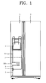
- FIG. 1 is a frontal view of a refrigerator having a heater according to the present disclosure
- FIG. 2 is a disassembled perspective view of the heater of the refrigerator of FIG. 1
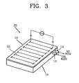
- FIG. 3 is an assembled perspective view of the heater of FIG. 2
- FIG. 4 is a planar view of the heater of FIG. 2 .
- a refrigerator having a heater for a dispenser comprises a freezing chamber door 1 configured to open and close a freezing chamber, a cooling chamber 2 configured to open and close a cooling chamber, a water supply pipe 3 configured to supply water from the outside, a heater 100 disposed in the freezing chamber door 1, and configured to heat water supplied from the water supply pipe 3, and a dispenser 4 configured to discharge hot water heated by the heater 100 or cool water.
- a switching valve 7 configured to distribute water supplied from the water supply pipe 3 to a cool water pipe 5 or a hot water pipe 6 is provided at an upper end of the water supply pipe 3.
- the heater 100 may be installed above or below the dispenser according to a type of the refrigerator. In this embodiment, the heater is installed below the dispenser.
- the heater 100 includes a water container 110 having a water path 111 including an inlet 112 and an outlet 113, and a heating element 120 coupled to the water container 110 so that water flowing along the water path 111 of the water container 110 can be heated.
- the water container 110 is formed in a rectangular parallelepiped shape. And, the water path 111 is formed on one side surface of the water container 110, i.e., a contact surface 110a in a zigzag shape, or a spiral shape (not shown).
- the inlet 112 and the outlet 113 of the water path 111 are formed on the same side surface of the water container 110 close to each other, so that water introduced into the inlet can be heat-exchanged with water discharged from the outlet 113.
- the water path 111 is formed on an entire region of the contact surface 110a, one side surface of the water container 110, so that a single water path 111 can be implemented from the inlet 112 to the outlet 113.
- the water path 111 is formed so that a first section (A) from the inlet 112 to an intermediate portion thereof can be heat-exchanged with a second section (B) from the intermediate portion thereof to the outlet 113.
- the first section (A) has a bent section from the inlet 112 to a predetermined part, but has a linear section at the rest part.
- the linear section passes through the edge of the water container 110.
- the second section (B) is bent several times in a zigzag form so as to increase a contact area to the heating element 120.
- a temperature stabilizing unit 115 is implemented by forming an outlet section (D) of the second section (B) in parallel to an inlet section (C) of the first section (A), i.e., the bent section of the first section (A). This is in order to allow cool water introduced via the inlet section (C) of the first section (A) to be heat-exchanged with hot water discharged via the outlet section (D) of the second section (B).
- the water path 111 may be configured such that a linear distance (L1) from the inlet 112 to the outlet 113 is shorter than a linear distance from the inlet 112 or the outlet 113 to an intermediate portion of the inlet 112 and the outlet 113.
- a linear distance indicates a distance from the outlet to an intermediate portion of the inlet 112 and the outlet 113.
- the water path 111 may be configured such that an interval between at least part of the first section (A) and at least part of the second section (B) in a vertical direction is greater than an interval between the inlet 112 and the outlet 113 in a vertical direction.
- the heating element 120 may be formed to have an area large enough to accommodate therein the entire part of the water path 111 of the water container 110. More specifically, the heating element 120 may be formed in a cubic or thin plate shape having the same area as the contact surface 110a of the water container 110.
- the heating element 120 may be provided with thermal lines 121 mounted therein, in correspondence to an entire area of the water path 111 of the water container 110, i.e., an area including the inlet section (C) of the first section (A) and the outlet section (D) of the second section (B). That is, the thermal lines 121 may be installed in the heating element 120 so as to have an area corresponding to the water container 110 including the temperature stabilizing unit 115.
- the refrigerator having the heater according to the present disclosure has the following advantages.
- water is guided to the inside of the refrigerator via the water supply pipe 3. Then, the water guided to the inside of the refrigerator is heated via the heater 100 disposed inside the refrigerator thus to be stored as hot water, or to be discharged out through the dispenser 4.
- the water path 111 is formed in a zigzag shape so that water passing through the heater 100 can be smoothly heat-exchanged with the heater 100. This may cause the water path 111 to be blocked, or water inside the water path 111 to have temperature increase to temperature more than a preset value, i.e., 95°C. As a result, steam is generated to heat the heating element 120. This may cause the thermal lines 121 mounted in the heating element 120 to have drastic temperature increase, resulting in damage of the thermal lines 121.
- the temperature stabilizing unit 115 is provided by arranging the inlet 112 and the outlet 113 of the water container 110 close to each other.
- cool water introduced to the water path 111 of the water container 110 from the hot water pipe 6 via the inlet 112 serves to cool hot water to be discharged to a hot water taking-out pipe 8 via the outlet 113 of the water container 110. This may prevent the hot water from being overheated to temperature more than a preset value.
- this may prevent damage of the thermal lines 121 of the heating element 120 due to overheating, the overheating occurring as water inside the water container 110 is overheated.
- the thermal lines 121 of the heating element 120 are arranged to correspond to the entire region of the water path 111 of the water container 110, i.e., the water path 111 including the temperature stabilizing unit 115.
- overheating of water is prevented by preventing the thermal lines 121 of the heating element 120 from being accommodated in part of the water path 111 of the water container 110, i.e., by allowing the temperature stabilizing unit 115 of the water path 111 not to correspond to the thermal lines 121.
- the water container 110 is formed in the same shape as that of the aforementioned embodiment.
- the heating element 120 is arranged such that the thermal lines mounted therein do not include the inlet section (C) and the outlet section (D) of the water container 120. Under this configuration, water inside the outlet section (D) is not rapidly heated, but slowly heated by the thermal lines 121. This may allow water to maintain a proper temperature at a section where overheating easily occurs.
- the heater 100 is formed in a plate shape.
- the heater 200 is formed in a tube shape.
- the heater 200 is formed in a tube shape where the water container 210 has an inner space 211 so as to form a water path. And, heating elements 220 are wound, in a band shape, on an outer circumferential surface of the water container 210.
- An upper end of the inner space 211 of the water container 210 is open, and a cap 212 is coupled to the opening.
- An inlet 213 through which a hot water pipe (not shown) is communicated with the inner space 211 is formed at a central region of the cap 212.
- an outlet 214 through which a hot water taking-out pipe (not shown) is communicated with the inner space 211 is formed close to the inlet 213.
- the inlet 213 is extended in a tube shape so that water introduced via the hot water pipe 6 can be guided to the bottom of the inner space 211 of the water container 210. And, an exit of the inner space 211 is inserted into the inlet 213 by a particular depth.
- An entrance of the outlet 214 is positioned on the bottom surface of the cap 212 such that water introduced into the inner space 211 via the inlet 213 is sufficiently heat-exchanged with the heating element 220 at the inner space 211.
- a temperature stabilizing unit 215 may be implemented at the cap 212 by forming a water path 216 from the inlet 213 to the outlet 214 in a zigzag or spiral shape.
- the heating element 220 may be provided on an entire region of an outer circumferential surface of the water container 210, i.e., a region of the cap 212.
- the heating element 220 may not be provided on the region of the cap 212.
- the water container is vertically installed such that a cover is positioned thereabove. This may cause hot water to rapidly upward move, resulting in a higher possibility that a heat pumping phenomenon occurs at the upside, than in the aforementioned plate-shape heater.
- overheating of the heater can be prevented by forming the temperature stabilizing unit at the cover.
- the heater according to embodiments of the present invention may be also applicable similarly to a water purifier and the like as well as the foregoing refrigerator.
Landscapes
- Engineering & Computer Science (AREA)
- Physics & Mathematics (AREA)
- Thermal Sciences (AREA)
- Chemical & Material Sciences (AREA)
- Combustion & Propulsion (AREA)
- Mechanical Engineering (AREA)
- General Engineering & Computer Science (AREA)
- Instantaneous Water Boilers, Portable Hot-Water Supply Apparatuses, And Control Of Portable Hot-Water Supply Apparatuses (AREA)
- Heat-Pump Type And Storage Water Heaters (AREA)
Abstract
Description
- The present invention relates to a heater for supplying hot water provided in a refrigerator or water purifier, and a hot water supplying device capable of preventing a heater from being reversely heated by hot water, and a refrigerator having the same.
- Generally, a refrigerator serves as an apparatus for storing food items in a fresh or frozen state for a predetermined time as a refrigerant repeatedly passes through a refrigerating cycle for compression, condensation, expansion and evaporation. Such refrigerator is considered as one of necessities.
- A recent large-sized refrigerator is provided with a dispenser through which ice or water stored therein is taken out without causing a user to open a door. This may prevent cool air inside the refrigerator from leaking to the outside, and may enhance a user's convenience. Especially, a dispenser for supplying hot water (hereinafter, will be referred to as hot water supplying dispenser) is being widely used at an office or other public facility, because it allows a user to conveniently make a cup of tea thereby.
- In a refrigerator having the hot water supplying dispenser, a hot water pipe is connected to a hot water taking-out pipe and a water supply pipe of the dispenser. And, a heater for heating the hot water pipe is installed at the door.
- In the conventional refrigerator, once water is supplied through a water supply pipe connected to a water source, the water is introduced to the hot water pipe via a switching valve of the water supply pipe. Then, the water is instantaneously heated via the heater, and is discharged to the dispenser via the hot water taking-out pipe.
- The heater may be formed in various manners. Recently, a so-called 'heat plate contact type heater' is being developed. In the heat plate contact type heater, a water container of a wide box shape has an opening covered by a heat plate having thermal lines therein, so that water contained in the water container can be heated by contacting the heat plate. In order to uniformly heat the water contained in the water container, a water path is formed in a zigzag shape in the water container so as to increase a contact area between the water contained in the water container and the heat plate.
- However, the heater of the hot water supplying dispenser has the following problems.
- Firstly, since an inlet and an outlet of the water path are provided at both sides of the water container, a distance between the inlet and the outlet is long. Therefore, if the outlet of the water path is blocked, steam is generated from the water path. This may cause water to heat the heat plate, resulting in damage of the thermal lines. Generally, the heater of the dispenser is designed to discharge hot water at temperature of about 95°C. If the heater discharges hot water at temperature more than 100°C, a heat jumping phenomenon occurs from the heater. This may cause the thermal lines to have drastic temperature increase, resulting in damage of the thermal lines.
- Therefore, an object of the present invention is to provide a hot water supplying device capable of preventing overheating of a heater by properly cooling hot water to be discharged, using low-temperature water introduced into the heater.
- According to an aspect of the present invention, there is provided a heater, including a water container formed with at least one water line having an inlet and outlet through which water flows; and a heating element combined with the water container to apply heat to the water flowing through the water line of the water container, wherein the water line is formed such that a first section from the inlet to the middle thereof is heat-exchanged with a second section from the middle to the outlet thereof.
- In order to accomplish another objective of the present invention, there is provided a hot water supply apparatus in which a dispenser is further provided to dispense hot water without opening the door, wherein a heater provided within the hot water supply apparatus to apply heat to the water has the foregoing configuration.
- In the heater and hot water supplying device according to embodiments of the present invention, the temperature stabilizing unit is formed by arranging an inlet and an outlet of a water container close to each other. Under this configuration, cool water introduced into a water path of the water container via the inlet serves to cool hot water to be discharged via the outlet of the water container. This may prevent the hot water from being overheated to temperature more than a preset value. As a result, this may prevent damage of thermal lines of a heating element, due to overheating, the overheating occurring as water inside the water container is overheated..
-
-
FIG. 1 is a frontal view of a refrigerator having a heater according to the present disclosure; -
FIG. 2 is a disassembled perspective view of the heater of the refrigerator ofFIG. 1 ; -
FIG. 3 is an assembled perspective view of the heater ofFIG. 2 ; -
FIG. 4 is a planar view of the heater ofFIG. 2 ; -
FIG. 5 is a planar view showing another embodiment of the heater ofFIG. 2 ; and -
FIGS. 6 and7 are frontal views showing other embodiments of the heater ofFIG. 1 . - Description will now be given in detail of a heater and hot water supplying device having the same according to an embodiment, with reference to the accompanying drawings.
-
FIG. 1 is a frontal view of a refrigerator having a heater according to the present disclosure,FIG. 2 is a disassembled perspective view of the heater of the refrigerator ofFIG. 1 ,FIG. 3 is an assembled perspective view of the heater ofFIG. 2 , andFIG. 4 is a planar view of the heater ofFIG. 2 . - As shown, a refrigerator having a heater for a dispenser according to the present disclosure comprises a
freezing chamber door 1 configured to open and close a freezing chamber, acooling chamber 2 configured to open and close a cooling chamber, awater supply pipe 3 configured to supply water from the outside, aheater 100 disposed in thefreezing chamber door 1, and configured to heat water supplied from thewater supply pipe 3, and adispenser 4 configured to discharge hot water heated by theheater 100 or cool water. - A
switching valve 7 configured to distribute water supplied from thewater supply pipe 3 to acool water pipe 5 or ahot water pipe 6 is provided at an upper end of thewater supply pipe 3. - The
heater 100 may be installed above or below the dispenser according to a type of the refrigerator. In this embodiment, the heater is installed below the dispenser. - As shown in
FIGS. 2 and3 , theheater 100 includes awater container 110 having awater path 111 including aninlet 112 and anoutlet 113, and aheating element 120 coupled to thewater container 110 so that water flowing along thewater path 111 of thewater container 110 can be heated. - The
water container 110 is formed in a rectangular parallelepiped shape. And, thewater path 111 is formed on one side surface of thewater container 110, i.e., acontact surface 110a in a zigzag shape, or a spiral shape (not shown). Theinlet 112 and theoutlet 113 of thewater path 111 are formed on the same side surface of thewater container 110 close to each other, so that water introduced into the inlet can be heat-exchanged with water discharged from theoutlet 113. - The
water path 111 is formed on an entire region of thecontact surface 110a, one side surface of thewater container 110, so that asingle water path 111 can be implemented from theinlet 112 to theoutlet 113. Here, thewater path 111 is formed so that a first section (A) from theinlet 112 to an intermediate portion thereof can be heat-exchanged with a second section (B) from the intermediate portion thereof to theoutlet 113. More specifically, as shown inFIG. 4 , the first section (A) has a bent section from theinlet 112 to a predetermined part, but has a linear section at the rest part. The linear section passes through the edge of thewater container 110. The second section (B) is bent several times in a zigzag form so as to increase a contact area to theheating element 120. - Preferably, a
temperature stabilizing unit 115 is implemented by forming an outlet section (D) of the second section (B) in parallel to an inlet section (C) of the first section (A), i.e., the bent section of the first section (A). This is in order to allow cool water introduced via the inlet section (C) of the first section (A) to be heat-exchanged with hot water discharged via the outlet section (D) of the second section (B). - To this end, the
water path 111 may be configured such that a linear distance (L1) from theinlet 112 to theoutlet 113 is shorter than a linear distance from theinlet 112 or theoutlet 113 to an intermediate portion of theinlet 112 and theoutlet 113. In this embodiment, a linear distance indicates a distance from the outlet to an intermediate portion of theinlet 112 and theoutlet 113. Alternatively, thewater path 111 may be configured such that an interval between at least part of the first section (A) and at least part of the second section (B) in a vertical direction is greater than an interval between theinlet 112 and theoutlet 113 in a vertical direction. - As shown in
FIGS. 2 to 4 , theheating element 120 may be formed to have an area large enough to accommodate therein the entire part of thewater path 111 of thewater container 110. More specifically, theheating element 120 may be formed in a cubic or thin plate shape having the same area as thecontact surface 110a of thewater container 110. Theheating element 120 may be provided withthermal lines 121 mounted therein, in correspondence to an entire area of thewater path 111 of thewater container 110, i.e., an area including the inlet section (C) of the first section (A) and the outlet section (D) of the second section (B). That is, thethermal lines 121 may be installed in theheating element 120 so as to have an area corresponding to thewater container 110 including thetemperature stabilizing unit 115. - The refrigerator having the heater according to the present disclosure has the following advantages.
- Once a user selects hot water using the
dispenser 4, water is guided to the inside of the refrigerator via thewater supply pipe 3. Then, the water guided to the inside of the refrigerator is heated via theheater 100 disposed inside the refrigerator thus to be stored as hot water, or to be discharged out through thedispenser 4. - Here, the
water path 111 is formed in a zigzag shape so that water passing through theheater 100 can be smoothly heat-exchanged with theheater 100. This may cause thewater path 111 to be blocked, or water inside thewater path 111 to have temperature increase to temperature more than a preset value, i.e., 95°C. As a result, steam is generated to heat theheating element 120. This may cause thethermal lines 121 mounted in theheating element 120 to have drastic temperature increase, resulting in damage of thethermal lines 121. - In order to solve such problems, in the present invention, the
temperature stabilizing unit 115 is provided by arranging theinlet 112 and theoutlet 113 of thewater container 110 close to each other. In this case, cool water introduced to thewater path 111 of thewater container 110 from thehot water pipe 6 via theinlet 112 serves to cool hot water to be discharged to a hot water taking-outpipe 8 via theoutlet 113 of thewater container 110. This may prevent the hot water from being overheated to temperature more than a preset value. - As a result, this may prevent damage of the
thermal lines 121 of theheating element 120 due to overheating, the overheating occurring as water inside thewater container 110 is overheated. - A heater according to another embodiment of the present invention will be explained.
- In the aforementioned embodiment, the
thermal lines 121 of theheating element 120 are arranged to correspond to the entire region of thewater path 111 of thewater container 110, i.e., thewater path 111 including thetemperature stabilizing unit 115. However, in this embodiment, as shown inFIG. 5 , overheating of water is prevented by preventing thethermal lines 121 of theheating element 120 from being accommodated in part of thewater path 111 of thewater container 110, i.e., by allowing thetemperature stabilizing unit 115 of thewater path 111 not to correspond to thethermal lines 121. - To this end, the
water container 110 is formed in the same shape as that of the aforementioned embodiment. However, unlike in the aforementioned embodiment, theheating element 120 is arranged such that the thermal lines mounted therein do not include the inlet section (C) and the outlet section (D) of thewater container 120. Under this configuration, water inside the outlet section (D) is not rapidly heated, but slowly heated by thethermal lines 121. This may allow water to maintain a proper temperature at a section where overheating easily occurs. - A heater for a dispenser according to still another embodiment of the present invention will be explained.
- In the aforementioned embodiments, the
heater 100 is formed in a plate shape. However, in this embodiment, as shown inFIGS. 6 and7 , theheater 200 is formed in a tube shape. - Referring to
FIG. 6 , theheater 200 is formed in a tube shape where thewater container 210 has aninner space 211 so as to form a water path. And,heating elements 220 are wound, in a band shape, on an outer circumferential surface of thewater container 210. - An upper end of the
inner space 211 of thewater container 210 is open, and acap 212 is coupled to the opening. Aninlet 213 through which a hot water pipe (not shown) is communicated with theinner space 211 is formed at a central region of thecap 212. And, anoutlet 214 through which a hot water taking-out pipe (not shown) is communicated with theinner space 211 is formed close to theinlet 213. - The
inlet 213 is extended in a tube shape so that water introduced via thehot water pipe 6 can be guided to the bottom of theinner space 211 of thewater container 210. And, an exit of theinner space 211 is inserted into theinlet 213 by a particular depth. - An entrance of the
outlet 214 is positioned on the bottom surface of thecap 212 such that water introduced into theinner space 211 via theinlet 213 is sufficiently heat-exchanged with theheating element 220 at theinner space 211. - As shown in
FIG. 7 , in order to increase a heat transfer area between theinlet 213 and theoutlet 214, atemperature stabilizing unit 215 may be implemented at thecap 212 by forming awater path 216 from theinlet 213 to theoutlet 214 in a zigzag or spiral shape. - As shown in
FIG. 6 , theheating element 220 may be provided on an entire region of an outer circumferential surface of thewater container 210, i.e., a region of thecap 212. Alternatively, as shown inFIG. 7 , theheating element 220 may not be provided on the region of thecap 212. - The operation and effects of this embodiment are similar to those of the aforementioned embodiments, and thus detailed explanations thereof will be omitted.
- In this embodiment, the water container is vertically installed such that a cover is positioned thereabove. This may cause hot water to rapidly upward move, resulting in a higher possibility that a heat pumping phenomenon occurs at the upside, than in the aforementioned plate-shape heater. In this embodiment, overheating of the heater can be prevented by forming the temperature stabilizing unit at the cover.
- The heater according to embodiments of the present invention may be also applicable similarly to a water purifier and the like as well as the foregoing refrigerator.
Claims (9)
- A heater, comprising:a water container formed with at least one water path having an inlet and outlet through which water flows; anda heating element combined with the water container to apply heat to the water flowing through the water path of the water container,wherein the water path is formed with a temperature stabilizing unit such that a first section from the inlet to the middle thereof is heat-exchanged with a second section from the intermediate portion to the outlet thereof.
- The heater of claim 1, wherein a linear distance from the inlet to the outlet of the water path is formed to be shorter than that from the inlet or outlet to an intermediate portion of the inlet and the outlet.
- The heater of claim 2, wherein the water path is formed with at least part of the region where a perpendicular directional interval between the first section and the second section is greater than that between the inlet and the outlet.
- The heater of claim 1, wherein the water path is configured such that at least part of a section from the inlet to the outlet is formed in a zigzag or spiral shape.
- The heater of claim 1, wherein the heating element is formed to accommodate at least part of the temperature stabilizing unit.
- The heater of claim 1, wherein the heating element is formed not to accommodate the temperature stabilizing unit.
- The heater of claim 1, wherein the water container is formed in a plate shape and the water path is formed in a groove shape at a side surface thereof, and the heating element is formed in a plate shape and combined with one side surface on which the water path of the water container is formed.
- The heater of claim 1, wherein the water container is formed in a plate shape having an internal space, and the heating element is formed to be wound around an outer circumferential surface of the water container, and the water container is formed such that an inlet is inserted from the upper end thereof to a predetermined depth while an outlet is formed at a side of the inlet to communicate with the internal space.
- A hot water supply apparatus in which a dispenser is further provided to dispense hot water without opening the door, wherein a heater provided within the hot water supply apparatus to apply heat to the water is made of any one of claims 1 through 8.
Applications Claiming Priority (2)
| Application Number | Priority Date | Filing Date | Title |
|---|---|---|---|
| KR1020090096919A KR101059879B1 (en) | 2009-10-12 | 2009-10-12 | Heater and hot water supply device |
| PCT/KR2010/006945 WO2011046335A2 (en) | 2009-10-12 | 2010-10-11 | Heater and hot water supply apparatus |
Publications (3)
| Publication Number | Publication Date |
|---|---|
| EP2489966A2 true EP2489966A2 (en) | 2012-08-22 |
| EP2489966A4 EP2489966A4 (en) | 2017-11-22 |
| EP2489966B1 EP2489966B1 (en) | 2024-04-10 |
Family
ID=43876681
Family Applications (1)
| Application Number | Title | Priority Date | Filing Date |
|---|---|---|---|
| EP10823574.8A Active EP2489966B1 (en) | 2009-10-12 | 2010-10-11 | Hot water supply apparatus and refrigerator having the same |
Country Status (4)
| Country | Link |
|---|---|
| US (1) | US20120195577A1 (en) |
| EP (1) | EP2489966B1 (en) |
| KR (1) | KR101059879B1 (en) |
| WO (1) | WO2011046335A2 (en) |
Families Citing this family (7)
| Publication number | Priority date | Publication date | Assignee | Title |
|---|---|---|---|---|
| US20140169774A1 (en) * | 2012-12-18 | 2014-06-19 | General Electric Company | Water heating assembly for a refrigerator appliance |
| KR101977215B1 (en) | 2017-07-19 | 2019-09-10 | 엘지전자 주식회사 | water dispensing apparatus and control method thereof |
| GB2566261B (en) * | 2017-09-01 | 2021-09-22 | Douwe Egberts Bv | Coffee-making Apparatus |
| US10563909B2 (en) | 2017-09-26 | 2020-02-18 | Midea Group Co., Ltd. | Refrigerator with a quick fill dispenser |
| CN107917573B (en) * | 2017-10-13 | 2020-03-17 | 青岛海尔股份有限公司 | Refrigerator with a door |
| US10955187B2 (en) | 2018-12-10 | 2021-03-23 | Midea Group Co., Ltd. | Refrigerator with quick fill dispenser incorporating removable fluid storage receptacle |
| US12104846B2 (en) | 2021-09-02 | 2024-10-01 | Midea Group Co., Ltd. | Refrigerator with quick fill dispenser incorporating removable fluid storage receptacle and combined inlet/outlet |
Family Cites Families (12)
| Publication number | Priority date | Publication date | Assignee | Title |
|---|---|---|---|---|
| NL135170C (en) * | 1962-10-31 | 1900-01-01 | ||
| JP3451708B2 (en) * | 1994-04-01 | 2003-09-29 | 松下電器産業株式会社 | Water heater |
| JP2004206301A (en) * | 2002-12-24 | 2004-07-22 | Benten:Kk | Sterilizer for water heater |
| KR100487799B1 (en) * | 2003-02-18 | 2005-05-06 | 엘지전자 주식회사 | Dispenser heater for refrigerator |
| KR100487815B1 (en) * | 2003-02-18 | 2005-05-06 | 엘지전자 주식회사 | Device for hot water dispensing for refrigerator |
| KR100561624B1 (en) * | 2003-06-20 | 2006-03-15 | 박성돈 | Electric boiler |
| KR200342870Y1 (en) | 2003-10-23 | 2004-02-19 | 주식회사 대우일렉트로닉스 | Refrigerators having water dispenser |
| NL1026873C2 (en) * | 2004-02-25 | 2005-08-26 | Ferro Techniek Holding Bv | Device and method for heating liquids, and basic structure. |
| KR100614227B1 (en) * | 2005-01-03 | 2006-08-21 | 엘지전자 주식회사 | Detachable hot water heater for refrigerator |
| KR100638908B1 (en) * | 2005-04-06 | 2006-10-25 | 엘지전자 주식회사 | Integrated heating tube |
| KR100763388B1 (en) * | 2005-04-11 | 2007-10-05 | 엘지전자 주식회사 | Apparatus for hot water supplying |
| KR20060107663A (en) * | 2005-04-11 | 2006-10-16 | 엘지전자 주식회사 | Instantaneous hot water supply device of the refrigerator and its control method |
-
2009
- 2009-10-12 KR KR1020090096919A patent/KR101059879B1/en not_active Expired - Fee Related
-
2010
- 2010-10-11 US US13/500,967 patent/US20120195577A1/en not_active Abandoned
- 2010-10-11 WO PCT/KR2010/006945 patent/WO2011046335A2/en not_active Ceased
- 2010-10-11 EP EP10823574.8A patent/EP2489966B1/en active Active
Non-Patent Citations (1)
| Title |
|---|
| See references of WO2011046335A2 * |
Also Published As
| Publication number | Publication date |
|---|---|
| WO2011046335A3 (en) | 2011-07-14 |
| EP2489966B1 (en) | 2024-04-10 |
| EP2489966A4 (en) | 2017-11-22 |
| US20120195577A1 (en) | 2012-08-02 |
| KR20110039885A (en) | 2011-04-20 |
| KR101059879B1 (en) | 2011-08-29 |
| WO2011046335A2 (en) | 2011-04-21 |
Similar Documents
| Publication | Publication Date | Title |
|---|---|---|
| EP2489966B1 (en) | Hot water supply apparatus and refrigerator having the same | |
| KR101312742B1 (en) | A beverage cooler, a refrigerator comprising such a beverage cooler and a method for cooling beverage | |
| US10266385B2 (en) | Cold-water generating tank, and water cooler equipped with same | |
| US20120000899A1 (en) | Heater for refrigerator and refrigerator including the same | |
| US8534089B2 (en) | Ice maker and refrigerator having the same | |
| KR20170135609A (en) | A refrigerator | |
| EP3964773B1 (en) | Refrigerator | |
| US20110203305A1 (en) | Ice and water system in refrigerator with stirring fan in ice chamber | |
| KR20230048261A (en) | Water purifying apparatus | |
| JP5450462B2 (en) | refrigerator | |
| US20180274828A1 (en) | On-door ice maker cooling | |
| JP5839224B2 (en) | Water server | |
| US10443914B2 (en) | Ice-making device for refrigerator | |
| WO2023202519A1 (en) | Refrigerator having air-cooled transparent ice-making device | |
| KR102474197B1 (en) | Refrigerator | |
| JP4959474B2 (en) | refrigerator | |
| JP5490853B2 (en) | refrigerator | |
| KR20080112710A (en) | Refrigerator | |
| JP5133634B2 (en) | refrigerator | |
| US20220412638A1 (en) | Refrigerator comprising module having multiple storage chambers | |
| US12196477B2 (en) | Refrigerator including module having plurality of storage chambers | |
| JP2013130355A (en) | Refrigerator | |
| CN110671862A (en) | Refrigerator and shelf for refrigerator | |
| KR20200031371A (en) | Refrigerator including a water heating module without hot water tank | |
| KR200251032Y1 (en) | Vending cart for draft beer |
Legal Events
| Date | Code | Title | Description |
|---|---|---|---|
| PUAI | Public reference made under article 153(3) epc to a published international application that has entered the european phase |
Free format text: ORIGINAL CODE: 0009012 |
|
| 17P | Request for examination filed |
Effective date: 20120424 |
|
| AK | Designated contracting states |
Kind code of ref document: A2 Designated state(s): AL AT BE BG CH CY CZ DE DK EE ES FI FR GB GR HR HU IE IS IT LI LT LU LV MC MK MT NL NO PL PT RO RS SE SI SK SM TR |
|
| DAX | Request for extension of the european patent (deleted) | ||
| A4 | Supplementary search report drawn up and despatched |
Effective date: 20171024 |
|
| RIC1 | Information provided on ipc code assigned before grant |
Ipc: F24H 1/12 20060101ALI20171018BHEP Ipc: F24H 1/14 20060101ALI20171018BHEP Ipc: F24H 9/20 20060101ALI20171018BHEP Ipc: F25D 23/08 20060101AFI20171018BHEP Ipc: F25D 25/00 20060101ALI20171018BHEP Ipc: F24D 17/00 20060101ALI20171018BHEP Ipc: F25D 11/00 20060101ALI20171018BHEP Ipc: F25D 23/12 20060101ALI20171018BHEP |
|
| STAA | Information on the status of an ep patent application or granted ep patent |
Free format text: STATUS: EXAMINATION IS IN PROGRESS |
|
| 17Q | First examination report despatched |
Effective date: 20200205 |
|
| GRAP | Despatch of communication of intention to grant a patent |
Free format text: ORIGINAL CODE: EPIDOSNIGR1 |
|
| STAA | Information on the status of an ep patent application or granted ep patent |
Free format text: STATUS: GRANT OF PATENT IS INTENDED |
|
| INTG | Intention to grant announced |
Effective date: 20231108 |
|
| RAP3 | Party data changed (applicant data changed or rights of an application transferred) |
Owner name: LG ELECTRONICS INC. |
|
| GRAS | Grant fee paid |
Free format text: ORIGINAL CODE: EPIDOSNIGR3 |
|
| GRAA | (expected) grant |
Free format text: ORIGINAL CODE: 0009210 |
|
| STAA | Information on the status of an ep patent application or granted ep patent |
Free format text: STATUS: THE PATENT HAS BEEN GRANTED |
|
| AK | Designated contracting states |
Kind code of ref document: B1 Designated state(s): AL AT BE BG CH CY CZ DE DK EE ES FI FR GB GR HR HU IE IS IT LI LT LU LV MC MK MT NL NO PL PT RO RS SE SI SK SM TR |
|
| REG | Reference to a national code |
Ref country code: GB Ref legal event code: FG4D |
|
| REG | Reference to a national code |
Ref country code: CH Ref legal event code: EP |
|
| REG | Reference to a national code |
Ref country code: DE Ref legal event code: R096 Ref document number: 602010069340 Country of ref document: DE |
|
| REG | Reference to a national code |
Ref country code: IE Ref legal event code: FG4D |
|
| REG | Reference to a national code |
Ref country code: LT Ref legal event code: MG9D |
|
| REG | Reference to a national code |
Ref country code: NL Ref legal event code: MP Effective date: 20240410 |
|
| REG | Reference to a national code |
Ref country code: AT Ref legal event code: MK05 Ref document number: 1675282 Country of ref document: AT Kind code of ref document: T Effective date: 20240410 |
|
| PG25 | Lapsed in a contracting state [announced via postgrant information from national office to epo] |
Ref country code: NL Free format text: LAPSE BECAUSE OF FAILURE TO SUBMIT A TRANSLATION OF THE DESCRIPTION OR TO PAY THE FEE WITHIN THE PRESCRIBED TIME-LIMIT Effective date: 20240410 |
|
| PG25 | Lapsed in a contracting state [announced via postgrant information from national office to epo] |
Ref country code: NL Free format text: LAPSE BECAUSE OF FAILURE TO SUBMIT A TRANSLATION OF THE DESCRIPTION OR TO PAY THE FEE WITHIN THE PRESCRIBED TIME-LIMIT Effective date: 20240410 |
|
| PG25 | Lapsed in a contracting state [announced via postgrant information from national office to epo] |
Ref country code: IS Free format text: LAPSE BECAUSE OF FAILURE TO SUBMIT A TRANSLATION OF THE DESCRIPTION OR TO PAY THE FEE WITHIN THE PRESCRIBED TIME-LIMIT Effective date: 20240810 |
|
| PG25 | Lapsed in a contracting state [announced via postgrant information from national office to epo] |
Ref country code: BG Free format text: LAPSE BECAUSE OF FAILURE TO SUBMIT A TRANSLATION OF THE DESCRIPTION OR TO PAY THE FEE WITHIN THE PRESCRIBED TIME-LIMIT Effective date: 20240410 |
|
| PG25 | Lapsed in a contracting state [announced via postgrant information from national office to epo] |
Ref country code: HR Free format text: LAPSE BECAUSE OF FAILURE TO SUBMIT A TRANSLATION OF THE DESCRIPTION OR TO PAY THE FEE WITHIN THE PRESCRIBED TIME-LIMIT Effective date: 20240410 Ref country code: FI Free format text: LAPSE BECAUSE OF FAILURE TO SUBMIT A TRANSLATION OF THE DESCRIPTION OR TO PAY THE FEE WITHIN THE PRESCRIBED TIME-LIMIT Effective date: 20240410 |
|
| PG25 | Lapsed in a contracting state [announced via postgrant information from national office to epo] |
Ref country code: GR Free format text: LAPSE BECAUSE OF FAILURE TO SUBMIT A TRANSLATION OF THE DESCRIPTION OR TO PAY THE FEE WITHIN THE PRESCRIBED TIME-LIMIT Effective date: 20240711 |
|
| PG25 | Lapsed in a contracting state [announced via postgrant information from national office to epo] |
Ref country code: PT Free format text: LAPSE BECAUSE OF FAILURE TO SUBMIT A TRANSLATION OF THE DESCRIPTION OR TO PAY THE FEE WITHIN THE PRESCRIBED TIME-LIMIT Effective date: 20240812 |
|
| PG25 | Lapsed in a contracting state [announced via postgrant information from national office to epo] |
Ref country code: ES Free format text: LAPSE BECAUSE OF FAILURE TO SUBMIT A TRANSLATION OF THE DESCRIPTION OR TO PAY THE FEE WITHIN THE PRESCRIBED TIME-LIMIT Effective date: 20240410 |
|
| PG25 | Lapsed in a contracting state [announced via postgrant information from national office to epo] |
Ref country code: AT Free format text: LAPSE BECAUSE OF FAILURE TO SUBMIT A TRANSLATION OF THE DESCRIPTION OR TO PAY THE FEE WITHIN THE PRESCRIBED TIME-LIMIT Effective date: 20240410 |
|
| PG25 | Lapsed in a contracting state [announced via postgrant information from national office to epo] |
Ref country code: PL Free format text: LAPSE BECAUSE OF FAILURE TO SUBMIT A TRANSLATION OF THE DESCRIPTION OR TO PAY THE FEE WITHIN THE PRESCRIBED TIME-LIMIT Effective date: 20240410 |
|
| PG25 | Lapsed in a contracting state [announced via postgrant information from national office to epo] |
Ref country code: LV Free format text: LAPSE BECAUSE OF FAILURE TO SUBMIT A TRANSLATION OF THE DESCRIPTION OR TO PAY THE FEE WITHIN THE PRESCRIBED TIME-LIMIT Effective date: 20240410 |
|
| PG25 | Lapsed in a contracting state [announced via postgrant information from national office to epo] |
Ref country code: PT Free format text: LAPSE BECAUSE OF FAILURE TO SUBMIT A TRANSLATION OF THE DESCRIPTION OR TO PAY THE FEE WITHIN THE PRESCRIBED TIME-LIMIT Effective date: 20240812 Ref country code: PL Free format text: LAPSE BECAUSE OF FAILURE TO SUBMIT A TRANSLATION OF THE DESCRIPTION OR TO PAY THE FEE WITHIN THE PRESCRIBED TIME-LIMIT Effective date: 20240410 Ref country code: NO Free format text: LAPSE BECAUSE OF FAILURE TO SUBMIT A TRANSLATION OF THE DESCRIPTION OR TO PAY THE FEE WITHIN THE PRESCRIBED TIME-LIMIT Effective date: 20240710 Ref country code: LV Free format text: LAPSE BECAUSE OF FAILURE TO SUBMIT A TRANSLATION OF THE DESCRIPTION OR TO PAY THE FEE WITHIN THE PRESCRIBED TIME-LIMIT Effective date: 20240410 Ref country code: IS Free format text: LAPSE BECAUSE OF FAILURE TO SUBMIT A TRANSLATION OF THE DESCRIPTION OR TO PAY THE FEE WITHIN THE PRESCRIBED TIME-LIMIT Effective date: 20240810 Ref country code: HR Free format text: LAPSE BECAUSE OF FAILURE TO SUBMIT A TRANSLATION OF THE DESCRIPTION OR TO PAY THE FEE WITHIN THE PRESCRIBED TIME-LIMIT Effective date: 20240410 Ref country code: GR Free format text: LAPSE BECAUSE OF FAILURE TO SUBMIT A TRANSLATION OF THE DESCRIPTION OR TO PAY THE FEE WITHIN THE PRESCRIBED TIME-LIMIT Effective date: 20240711 Ref country code: FI Free format text: LAPSE BECAUSE OF FAILURE TO SUBMIT A TRANSLATION OF THE DESCRIPTION OR TO PAY THE FEE WITHIN THE PRESCRIBED TIME-LIMIT Effective date: 20240410 Ref country code: ES Free format text: LAPSE BECAUSE OF FAILURE TO SUBMIT A TRANSLATION OF THE DESCRIPTION OR TO PAY THE FEE WITHIN THE PRESCRIBED TIME-LIMIT Effective date: 20240410 Ref country code: BG Free format text: LAPSE BECAUSE OF FAILURE TO SUBMIT A TRANSLATION OF THE DESCRIPTION OR TO PAY THE FEE WITHIN THE PRESCRIBED TIME-LIMIT Effective date: 20240410 Ref country code: AT Free format text: LAPSE BECAUSE OF FAILURE TO SUBMIT A TRANSLATION OF THE DESCRIPTION OR TO PAY THE FEE WITHIN THE PRESCRIBED TIME-LIMIT Effective date: 20240410 Ref country code: RS Free format text: LAPSE BECAUSE OF FAILURE TO SUBMIT A TRANSLATION OF THE DESCRIPTION OR TO PAY THE FEE WITHIN THE PRESCRIBED TIME-LIMIT Effective date: 20240710 |
|
| REG | Reference to a national code |
Ref country code: DE Ref legal event code: R097 Ref document number: 602010069340 Country of ref document: DE |
|
| PG25 | Lapsed in a contracting state [announced via postgrant information from national office to epo] |
Ref country code: DK Free format text: LAPSE BECAUSE OF FAILURE TO SUBMIT A TRANSLATION OF THE DESCRIPTION OR TO PAY THE FEE WITHIN THE PRESCRIBED TIME-LIMIT Effective date: 20240410 |
|
| PG25 | Lapsed in a contracting state [announced via postgrant information from national office to epo] |
Ref country code: EE Free format text: LAPSE BECAUSE OF FAILURE TO SUBMIT A TRANSLATION OF THE DESCRIPTION OR TO PAY THE FEE WITHIN THE PRESCRIBED TIME-LIMIT Effective date: 20240410 |
|
| PG25 | Lapsed in a contracting state [announced via postgrant information from national office to epo] |
Ref country code: CZ Free format text: LAPSE BECAUSE OF FAILURE TO SUBMIT A TRANSLATION OF THE DESCRIPTION OR TO PAY THE FEE WITHIN THE PRESCRIBED TIME-LIMIT Effective date: 20240410 |
|
| PG25 | Lapsed in a contracting state [announced via postgrant information from national office to epo] |
Ref country code: SK Free format text: LAPSE BECAUSE OF FAILURE TO SUBMIT A TRANSLATION OF THE DESCRIPTION OR TO PAY THE FEE WITHIN THE PRESCRIBED TIME-LIMIT Effective date: 20240410 Ref country code: RO Free format text: LAPSE BECAUSE OF FAILURE TO SUBMIT A TRANSLATION OF THE DESCRIPTION OR TO PAY THE FEE WITHIN THE PRESCRIBED TIME-LIMIT Effective date: 20240410 |
|
| PG25 | Lapsed in a contracting state [announced via postgrant information from national office to epo] |
Ref country code: SM Free format text: LAPSE BECAUSE OF FAILURE TO SUBMIT A TRANSLATION OF THE DESCRIPTION OR TO PAY THE FEE WITHIN THE PRESCRIBED TIME-LIMIT Effective date: 20240410 |
|
| PG25 | Lapsed in a contracting state [announced via postgrant information from national office to epo] |
Ref country code: SM Free format text: LAPSE BECAUSE OF FAILURE TO SUBMIT A TRANSLATION OF THE DESCRIPTION OR TO PAY THE FEE WITHIN THE PRESCRIBED TIME-LIMIT Effective date: 20240410 Ref country code: SK Free format text: LAPSE BECAUSE OF FAILURE TO SUBMIT A TRANSLATION OF THE DESCRIPTION OR TO PAY THE FEE WITHIN THE PRESCRIBED TIME-LIMIT Effective date: 20240410 Ref country code: RO Free format text: LAPSE BECAUSE OF FAILURE TO SUBMIT A TRANSLATION OF THE DESCRIPTION OR TO PAY THE FEE WITHIN THE PRESCRIBED TIME-LIMIT Effective date: 20240410 Ref country code: EE Free format text: LAPSE BECAUSE OF FAILURE TO SUBMIT A TRANSLATION OF THE DESCRIPTION OR TO PAY THE FEE WITHIN THE PRESCRIBED TIME-LIMIT Effective date: 20240410 Ref country code: DK Free format text: LAPSE BECAUSE OF FAILURE TO SUBMIT A TRANSLATION OF THE DESCRIPTION OR TO PAY THE FEE WITHIN THE PRESCRIBED TIME-LIMIT Effective date: 20240410 Ref country code: CZ Free format text: LAPSE BECAUSE OF FAILURE TO SUBMIT A TRANSLATION OF THE DESCRIPTION OR TO PAY THE FEE WITHIN THE PRESCRIBED TIME-LIMIT Effective date: 20240410 |
|
| PG25 | Lapsed in a contracting state [announced via postgrant information from national office to epo] |
Ref country code: IT Free format text: LAPSE BECAUSE OF FAILURE TO SUBMIT A TRANSLATION OF THE DESCRIPTION OR TO PAY THE FEE WITHIN THE PRESCRIBED TIME-LIMIT Effective date: 20240410 |
|
| PLBE | No opposition filed within time limit |
Free format text: ORIGINAL CODE: 0009261 |
|
| STAA | Information on the status of an ep patent application or granted ep patent |
Free format text: STATUS: NO OPPOSITION FILED WITHIN TIME LIMIT |
|
| 26N | No opposition filed |
Effective date: 20250113 |
|
| PG25 | Lapsed in a contracting state [announced via postgrant information from national office to epo] |
Ref country code: SI Free format text: LAPSE BECAUSE OF FAILURE TO SUBMIT A TRANSLATION OF THE DESCRIPTION OR TO PAY THE FEE WITHIN THE PRESCRIBED TIME-LIMIT Effective date: 20240410 |
|
| REG | Reference to a national code |
Ref country code: CH Ref legal event code: PL |
|
| GBPC | Gb: european patent ceased through non-payment of renewal fee |
Effective date: 20241011 |
|
| PG25 | Lapsed in a contracting state [announced via postgrant information from national office to epo] |
Ref country code: MC Free format text: LAPSE BECAUSE OF FAILURE TO SUBMIT A TRANSLATION OF THE DESCRIPTION OR TO PAY THE FEE WITHIN THE PRESCRIBED TIME-LIMIT Effective date: 20240410 |
|
| PG25 | Lapsed in a contracting state [announced via postgrant information from national office to epo] |
Ref country code: GB Free format text: LAPSE BECAUSE OF NON-PAYMENT OF DUE FEES Effective date: 20241011 |
|
| PG25 | Lapsed in a contracting state [announced via postgrant information from national office to epo] |
Ref country code: LU Free format text: LAPSE BECAUSE OF NON-PAYMENT OF DUE FEES Effective date: 20241011 Ref country code: BE Free format text: LAPSE BECAUSE OF NON-PAYMENT OF DUE FEES Effective date: 20241031 |
|
| PG25 | Lapsed in a contracting state [announced via postgrant information from national office to epo] |
Ref country code: FR Free format text: LAPSE BECAUSE OF NON-PAYMENT OF DUE FEES Effective date: 20241031 |
|
| PG25 | Lapsed in a contracting state [announced via postgrant information from national office to epo] |
Ref country code: CH Free format text: LAPSE BECAUSE OF NON-PAYMENT OF DUE FEES Effective date: 20241031 |
|
| REG | Reference to a national code |
Ref country code: BE Ref legal event code: MM Effective date: 20241031 |
|
| PG25 | Lapsed in a contracting state [announced via postgrant information from national office to epo] |
Ref country code: SE Free format text: LAPSE BECAUSE OF FAILURE TO SUBMIT A TRANSLATION OF THE DESCRIPTION OR TO PAY THE FEE WITHIN THE PRESCRIBED TIME-LIMIT Effective date: 20240410 |
|
| PG25 | Lapsed in a contracting state [announced via postgrant information from national office to epo] |
Ref country code: IE Free format text: LAPSE BECAUSE OF NON-PAYMENT OF DUE FEES Effective date: 20241011 |
|
| PGFP | Annual fee paid to national office [announced via postgrant information from national office to epo] |
Ref country code: DE Payment date: 20250908 Year of fee payment: 16 |
|
| PG25 | Lapsed in a contracting state [announced via postgrant information from national office to epo] |
Ref country code: CY Free format text: LAPSE BECAUSE OF FAILURE TO SUBMIT A TRANSLATION OF THE DESCRIPTION OR TO PAY THE FEE WITHIN THE PRESCRIBED TIME-LIMIT; INVALID AB INITIO Effective date: 20101011 |
|
| PG25 | Lapsed in a contracting state [announced via postgrant information from national office to epo] |
Ref country code: HU Free format text: LAPSE BECAUSE OF FAILURE TO SUBMIT A TRANSLATION OF THE DESCRIPTION OR TO PAY THE FEE WITHIN THE PRESCRIBED TIME-LIMIT; INVALID AB INITIO Effective date: 20101011 |
|
| PG25 | Lapsed in a contracting state [announced via postgrant information from national office to epo] |
Ref country code: TR Free format text: LAPSE BECAUSE OF FAILURE TO SUBMIT A TRANSLATION OF THE DESCRIPTION OR TO PAY THE FEE WITHIN THE PRESCRIBED TIME-LIMIT Effective date: 20240410 |
|
| PG25 | Lapsed in a contracting state [announced via postgrant information from national office to epo] |
Ref country code: LT Free format text: LAPSE BECAUSE OF FAILURE TO SUBMIT A TRANSLATION OF THE DESCRIPTION OR TO PAY THE FEE WITHIN THE PRESCRIBED TIME-LIMIT Effective date: 20240410 |