EP2489937A2 - Combustor assembly for use in a turbine engine and methods of fabricating same - Google Patents
Combustor assembly for use in a turbine engine and methods of fabricating same Download PDFInfo
- Publication number
- EP2489937A2 EP2489937A2 EP12155362A EP12155362A EP2489937A2 EP 2489937 A2 EP2489937 A2 EP 2489937A2 EP 12155362 A EP12155362 A EP 12155362A EP 12155362 A EP12155362 A EP 12155362A EP 2489937 A2 EP2489937 A2 EP 2489937A2
- Authority
- EP
- European Patent Office
- Prior art keywords
- transition piece
- upstream
- downstream
- combustor
- cooling passages
- Prior art date
- Legal status (The legal status is an assumption and is not a legal conclusion. Google has not performed a legal analysis and makes no representation as to the accuracy of the status listed.)
- Granted
Links
Images



Classifications
-
- F—MECHANICAL ENGINEERING; LIGHTING; HEATING; WEAPONS; BLASTING
- F23—COMBUSTION APPARATUS; COMBUSTION PROCESSES
- F23R—GENERATING COMBUSTION PRODUCTS OF HIGH PRESSURE OR HIGH VELOCITY, e.g. GAS-TURBINE COMBUSTION CHAMBERS
- F23R3/00—Continuous combustion chambers using liquid or gaseous fuel
- F23R3/002—Wall structures
-
- F—MECHANICAL ENGINEERING; LIGHTING; HEATING; WEAPONS; BLASTING
- F01—MACHINES OR ENGINES IN GENERAL; ENGINE PLANTS IN GENERAL; STEAM ENGINES
- F01D—NON-POSITIVE DISPLACEMENT MACHINES OR ENGINES, e.g. STEAM TURBINES
- F01D9/00—Stators
- F01D9/02—Nozzles; Nozzle boxes; Stator blades; Guide conduits, e.g. individual nozzles
- F01D9/023—Transition ducts between combustor cans and first stage of the turbine in gas-turbine engines; their cooling or sealings
-
- F—MECHANICAL ENGINEERING; LIGHTING; HEATING; WEAPONS; BLASTING
- F23—COMBUSTION APPARATUS; COMBUSTION PROCESSES
- F23R—GENERATING COMBUSTION PRODUCTS OF HIGH PRESSURE OR HIGH VELOCITY, e.g. GAS-TURBINE COMBUSTION CHAMBERS
- F23R3/00—Continuous combustion chambers using liquid or gaseous fuel
- F23R3/42—Continuous combustion chambers using liquid or gaseous fuel characterised by the arrangement or form of the flame tubes or combustion chambers
- F23R3/60—Support structures; Attaching or mounting means
-
- F—MECHANICAL ENGINEERING; LIGHTING; HEATING; WEAPONS; BLASTING
- F05—INDEXING SCHEMES RELATING TO ENGINES OR PUMPS IN VARIOUS SUBCLASSES OF CLASSES F01-F04
- F05D—INDEXING SCHEME FOR ASPECTS RELATING TO NON-POSITIVE-DISPLACEMENT MACHINES OR ENGINES, GAS-TURBINES OR JET-PROPULSION PLANTS
- F05D2260/00—Function
- F05D2260/20—Heat transfer, e.g. cooling
- F05D2260/202—Heat transfer, e.g. cooling by film cooling
-
- F—MECHANICAL ENGINEERING; LIGHTING; HEATING; WEAPONS; BLASTING
- F23—COMBUSTION APPARATUS; COMBUSTION PROCESSES
- F23R—GENERATING COMBUSTION PRODUCTS OF HIGH PRESSURE OR HIGH VELOCITY, e.g. GAS-TURBINE COMBUSTION CHAMBERS
- F23R2900/00—Special features of, or arrangements for continuous combustion chambers; Combustion processes therefor
- F23R2900/03042—Film cooled combustion chamber walls or domes
-
- Y—GENERAL TAGGING OF NEW TECHNOLOGICAL DEVELOPMENTS; GENERAL TAGGING OF CROSS-SECTIONAL TECHNOLOGIES SPANNING OVER SEVERAL SECTIONS OF THE IPC; TECHNICAL SUBJECTS COVERED BY FORMER USPC CROSS-REFERENCE ART COLLECTIONS [XRACs] AND DIGESTS
- Y02—TECHNOLOGIES OR APPLICATIONS FOR MITIGATION OR ADAPTATION AGAINST CLIMATE CHANGE
- Y02T—CLIMATE CHANGE MITIGATION TECHNOLOGIES RELATED TO TRANSPORTATION
- Y02T50/00—Aeronautics or air transport
- Y02T50/60—Efficient propulsion technologies, e.g. for aircraft
-
- Y—GENERAL TAGGING OF NEW TECHNOLOGICAL DEVELOPMENTS; GENERAL TAGGING OF CROSS-SECTIONAL TECHNOLOGIES SPANNING OVER SEVERAL SECTIONS OF THE IPC; TECHNICAL SUBJECTS COVERED BY FORMER USPC CROSS-REFERENCE ART COLLECTIONS [XRACs] AND DIGESTS
- Y10—TECHNICAL SUBJECTS COVERED BY FORMER USPC
- Y10T—TECHNICAL SUBJECTS COVERED BY FORMER US CLASSIFICATION
- Y10T29/00—Metal working
- Y10T29/49—Method of mechanical manufacture
- Y10T29/49346—Rocket or jet device making
Definitions
- the subject matter described relates generally to turbine engines and more particularly, to combustor assemblies for use with turbine engines.
- At least some known gas turbine engines include a combustion assembly that is coupled to a turbine section. At least some known combustion assemblies include a combustor liner that is coupled to a transition piece. The transition piece is coupled to the turbine section with a transition piece frame assembly.
- known gas turbine engines use cooling air to cool a combustion assembly included within the engine. Often cooling air is supplied from a compressor that is coupled in flow communication upstream from the combustion assembly. More specifically, in at least some known turbine engines, cooling air is discharged from the compressor into a plenum that extends at least partially around the transition piece of the combustor assembly.
- a portion of the cooling air entering the plenum is supplied to an impingement sleeve that circumscribes the transition piece, prior to the air being channeled into a channel defined between the impingement sleeve and the transition piece. Cooling air entering the channel is discharged downstream into a second channel defined between a combustor liner and a flowsleeve.
- transition piece frame assembly A portion of cooling air entering the cooling channel is channeled towards transition piece frame assembly.
- transition piece frame assemblies include a plurality of cooling passages that channel cooling air through the transition piece frame assembly in a non-uniform air flow pattern.
- the non-uniform flow distribution may create temperature variations throughout the transition piece frame assembly and may cause an uneven heat transfer between the transition piece frame assembly and the cooling air. Over time, the uneven heat transfer may result in thermal cracking and/or damage to the transition piece frame assembly. Over time continued operation with a damaged transition piece frame assembly may reduce the useful life of the transition piece frame assembly and/or increase the cost of maintaining and operating the turbine engine.
- the invention resides in a combustor assembly including a combustor liner that defines a combustion chamber there within and a transition piece that includes a forward portion that is coupled to the combustion liner and an aft portion that extends from the forward portion.
- the aft portion includes a transition piece frame.
- the transition piece frame includes an upstream surface, a downstream surface, and a radially inner surface extending between the upstream and downstream surfaces.
- the radially inner surface includes a leading edge that extends between the radially inner surface and the upstream surface.
- a plurality of first cooling passages extend from the upstream surface to the downstream surface. Each of the first cooling passages is oriented obliquely with respect to the leading edge from the upstream surface towards the downstream surface.
- the invention resides in a turbine engine including a compressor, and a combustor that is in flow communication with the compressor to receive at least some fluid discharged by the compressor.
- the combustor includes a plurality of combustor assemblies, as described above, at least one of the combustor assemblies including a casing, that includes a plenum, the combustor liner assembly coupled to the casing, and the combustion liner is at least partially positioned within the plenum.
- the invention resides in a method of fabricating a combustor assembly for use in a turbine engine.
- the method includes coupling a combustor liner assembly to a casing such that the combustion liner is at least partially positioned within the casing to define a combustion chamber therein.
- a transition piece that includes a transition piece frame is formed.
- the transition piece frame includes an upstream surface, a downstream surface, and a radially inner surface that extends between the upstream and downstream surfaces.
- the radially inner surface includes a leading edge that extends between the radially inner surface and the upstream surface.
- a plurality of first cooling passages is defined through the transition piece frame.
- Each of the first cooling passages extends from the upstream surface towards the downstream surface and is oriented at a first oblique angle with respect to the leading edge.
- the transition piece is coupled to the combustor liner for channeling combustion gases from the combustion chamber to a turbine section.
- the exemplary methods and systems described herein overcome at least some disadvantages of known combustor assemblies by providing a transition piece frame that channels a substantially uniform flow distribution of cooling fluid through the transition piece frame to facilitate enhanced heat transfer between the cooling fluid and the transition piece frame. More specifically, the embodiments described herein provide a transition piece frame that includes a cooling passage that enables a flow of cooling fluid having a uniform distribution to be channeled through the transition piece frame. The uniform distribution of cooling fluid facilitates substantially evenly reducing a temperature of the transition piece frame, which facilitates increasing the operating life of the combustor assembly.
- upstream refers to a forward end of a turbine engine
- downstream refers to an aft end of a turbine engine
- FIG. 1 is a schematic view of an exemplary turbine engine 10.
- Turbine engine 10 includes an intake section 12, a compressor section 14 that is downstream from intake section 12, a combustor section 16 downstream from compressor section 14, a turbine section 18 downstream from combustor section 16, and an exhaust section 20 downstream from turbine section 18.
- Turbine section 18 is coupled to compressor section 14 via a rotor assembly 22 that includes a shaft 24.
- Combustor section 16 includes a plurality of combustor assemblies 26 that are each coupled in flow communication with the compressor section 14.
- a fuel nozzle assembly 28 is coupled to each combustor assembly 26.
- Turbine section 18 is rotatably coupled to compressor section 14 and to a load 29 such as, but not limited to, an electrical generator and/or a mechanical drive application.
- turbine engine 10 is a MS9001E engine, commercially available from General Electric Company, Schenectady, NY. It should be noted that turbine engine 10 is exemplary only, and that the present invention is not limited to being used only with turbine engine 10, but rather may instead be implemented within any turbine engine that functions as described herein.
- Combustor assembly 26 injects fuel, for example, natural gas and/or fuel oil, into the air flow, ignites the fuel-air mixture to expand the fuel-air mixture through combustion, and generates high temperature combustion gases. Combustion gases are discharged from combustor assembly 26 towards turbine section 18 wherein thermal energy in the gases is converted to mechanical rotational energy. Combustion gases impart rotational energy to turbine section 18 and to rotor assembly 22, which subsequently provides rotational power to compressor section 14.
- fuel for example, natural gas and/or fuel oil
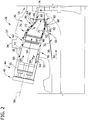
- FIG. 2 is an enlarged cross-sectional illustration of a portion of combustor assembly 26.
- combustor assembly 26 is coupled in flow communication with turbine section 18 and with compressor section 14.
- compressor section 14 includes a diffuser 30 that is coupled in flow communication with a discharge plenum 32 that enables air to be channeled downstream from compressor section 14 towards combustor assembly 26.
- combustor assembly 26 includes a combustor casing 34 that defines a chamber 36 therein and a combustor liner 38 that is positioned within chamber 36.
- a dome plate 40 is coupled to a substantially cylindrical combustor flowsleeve 42 that includes a forward section 44 and an aft section 46.
- Flowsleeve 42 is coupled to combustor casing 34 and is at least partially positioned within chamber 36.
- Combustor liner 38 is positioned within flowsleeve 42 and is supported by, flowsleeve 42.
- flowsleeve 42 is coupled radially outwardly from combustor liner 38 such that an annular cooling passage 48 is defined between flowsleeve 42 and combustor liner 38.
- Flowsleeve 42 and combustor casing 34 substantially isolate combustor liner 38 and its associated combustion processes from surrounding turbine components.
- a dome plate 40 is coupled to forward section 44 of flowsleeve 42 to support a plurality of fuel nozzles 50 that are positioned within flowsleeve 42.
- combustor liner 38 includes a substantially cylindrically-shaped inner surface 52 that defines an annular combustion chamber 54 that has a centerline axis 56 extending therethrough. Combustor liner 38 is also coupled to fuel nozzles 50 that channel fuel into combustion chamber 54. Combustion chamber 54 defines a combustion gas flow path 58 that extends from fuel nozzles 50 to turbine section 18. Annular cooling passage 48 channels cooling fluid across an outer surface 60 of combustor liner 38 towards fuel nozzles 50.
- flowsleeve 42 includes an inlet opening 62 that defines a flow path into cooling passage 48.
- transition piece 64 is coupled to combustor liner 38 for use in channeling combustion gases from combustor liner 38 towards turbine section 18.
- transition piece 64 includes a transition piece frame 66 that extends from a downstream portion, i.e. an aft portion 68 of transition piece 64.
- transition piece frame 66 is formed integrally with transition piece 64.
- transition piece frame 66 is coupled to transition piece 64 with a weld, a fastener, a bolt, and/or any other suitable method to coupled transition piece frame 66 to transition piece 64 to enable transition piece frame 66 to function as described herein.
- transition piece 64 includes an inner surface 70 that defmes a guide cavity 72 that channels combustion gases from combustion chamber 54 downstream to a turbine nozzle 74. Combustion gases generated within combustion chamber 54 are channeled along path 58 towards transition piece 64. An upstream portion, i.e. a forward portion 76 of transition piece 64 is coupled to liner aft section 46. In one embodiment, combustor liner 38 is at least partially inserted into forward portion 76 such that combustion chamber 54 is positioned in flow communication with guide cavity 72, and such that combustion chamber 54 and guide cavity 72 are substantially isolated from plenum 32.
- aft portion 68 of transition piece 64 extends from forward portion 76 such that transition piece frame 66 is positioned adjacent turbine nozzle 74.
- transition piece frame 66 is coupled to casing 34 to support transition piece frame 66 from casing 34.
- forward portion 76 of transition piece frame 66 is couple to casing 34.
- an impingement sleeve 80 is spaced a distance radially outwardly from transition piece 64. More specifically, a downstream end 82 of impingement sleeve 80 is coupled to transition piece frame 66 such that impingement sleeve 80 is positioned radially outwardly from transition piece 64 such that a transition piece cooling passage 84 is defined between impingement sleeve 80 and transition piece 64.
- a plurality of openings 86 extending through impingement sleeve 80 enable a portion of air flow from compressor discharge plenum 32 to be channeled into cooling passage 84.
- a plurality of cooling passages 88 are defined within transition piece frame 66.
- Each cooling passage 88 is sized and shaped to channel a portion of air flow from compressor discharge plenum 32 through cooling passage 88 to facilitate reducing a temperature of transition piece frame 66.
- compressor section 14 is driven by turbine section 18 via shaft 24 (shown in FIG. 1 ).
- compressed air 90 is discharged into diffuser 30.
- the majority of compressed air 90 discharged from compressor section 14 into diffuser 30 is channeled through compressor discharge plenum 32 towards combustor assembly 26.
- a first flow 92 of pressurized compressed air 90 within plenum 32 is channeled into cooling passage 84 through impingement sleeve openings 86.
- Air 90 entering cooling passage 84 is then discharged from cooling passage 84 towards fuel nozzles 50.
- Air 90 is then mixed with fuel discharged from fuel nozzles 50 and ignited within combustion chamber 54 to form a combustion gas stream 94.
- Combustion gases 94 are channeled from chamber 54 through transition piece guide cavity 72 towards turbine nozzle 74.
- a second flow 96 of pressurized compressed air 90 within plenum 32 is channeled from cooling passage 84 towards transition piece frame 66 and into cooling passages 88. Air 90 entering cooling passages 88 facilitates reducing a temperature of transition piece 64 during operation of combustor assembly 26.
- FIG. 3 is a sectional view of an exemplary embodiment of transition piece frame 66 shown in FIG. 2 and taken along line 3-3.
- FIG. 4 is a partial cross-sectional view of transition piece frame 66 and taken along line 4-4.
- FIG. 5 is a partial cross-sectional view of transition piece frame 66 and taken along line 5-5.
- transition piece frame 66 includes an upstream surface 98, downstream surface 100, a radially inner surface 102, and a radially outer surface 104.
- Upstream surface 98 is spaced a distance from downstream surface 100, and surfaces 102 and 104 each extend generally axially between surfaces 98 and 100.
- Radially inner surface 102 defmes an inner cavity 106 that extends along a centerline axis 108.
- cavity 106 has a substantially rectangular shape that at least partially defines combustion gas flow path 58 and that provides flow communication between transition piece guide cavity 72 and turbine section 18. More specifically, in the exemplary embodiment, transition piece frame 66 has a height H that is defmed between surfaces 102 and 104, and an axial width W that is defined between surfaces 98 and 100.
- inner surface 102 extends between a leading edge 110 and a trailing edge 112.
- Leading edge 110 extends between radially inner surface 102 and upstream surface 98.
- Trailing edge 112 extends between radially inner surface 102 and downstream surface 100.
- Edges 110 and 112 are oriented substantially perpendicular with respect to centerline axis 108.
- edges 110 and 112 define a transverse axis 114 that is perpendicular to centerline axis 108.
- upstream surface 98 includes a projection 120 that extends outwardly from upstream surface 98 towards transition piece 64.
- Projection 120 is sized, shaped, and oriented to facilitate coupling transition piece 64 to transition piece frame 66.
- a first axial width W 1 of radially inner surface 102 is larger than a second axial width W 2 of radially outer surface 104.
- axes X, Y, and Z each extend substantially perpendicularly through transition piece frame 66 and are oriented to define a three-dimensional Cartesian coordinate system that is oriented such that the Z-axis is aligned substantially coaxially with centerline axis 108, and such that the X-axis is substantially coaxial with transverse axis 114.
- transition piece frame 66 includes a plurality of cooling passages 88 that extend from upstream surface 98 towards downstream surface 100.
- Upstream surface 98 includes a plurality of upstream openings 122 defined therein that provide flow communication between cooling passage 88 and plenum 32.
- Downstream surface 100 includes a plurality of downstream openings 126 defined therein that provide flow communication between plenum 32 and turbine section 18.
- each cooling passage 88 extends between opening 122 and downstream opening 126 and defmes a longitudinal axis 130 that extends between upstream opening 122 and downstream opening 126.
- Each cooling passage 88 has an axial length L measured between upstream opening 122 and downstream opening 126 and along longitudinal axis 130.
- Cooling passage 88 is sized and shaped to channel cooling fluid from plenum 32 through transition piece 64 towards turbine section 18 to facilitate cooling transition piece 64.
- Cooling passage 88 extends from upstream opening 122 to downstream opening 126 and is oriented at a first oblique angle ⁇ 1 with respect to radially inner surface 102.
- openings 122 are defined at a first radial distance D 1 from radially inner surface 102, and downstream openings 126 are defmed at a second radial distance D 2 from radially inner surface 102.
- distance D 2 is shorter than distance D 1 .
- second radial distance D 2 is approximately the same length as first radial distance D 1 such that each cooling passage 88 is oriented substantially parallel to radially inner surface 102 and/or to centerline axis 108.
- second radial distance D 2 may be longer than first radial distance D 1 .
- transition piece frame 66 includes at least one first cooling passage 132 and at least one second cooling passage 134.
- First cooling passage 132 extends from a first upstream opening 136 to a first downstream opening 138.
- first downstream opening 138 is offset a circumferential distance D 3 along transverse axis 114 with respect to first upstream opening 136.
- First cooling passage 132 extends between first upstream opening 136 and first downstream opening 138, and is oriented at a second oblique angle ⁇ 2 with respect to leading edge 110.
- Second cooling passage 134 extends between a second upstream opening 140 and a second downstream opening 142, and is oriented substantially perpendicularly to leading edge 110.
- first cooling passage 132 has a first axial length L 1 measured between first upstream opening 136 and first downstream opening 138.
- Second cooling passage 134 has a second axial length L 2 measured between second upstream opening 140 and second downstream opening 142. In the exemplary embodiment, length L 2 is shorter than length L 1 .
- transition piece frame 66 includes at least one third cooling passage 144 that extends between a third upstream opening 146 and a third downstream opening 148.
- Third downstream opening 148 is offset a circumferential distance D 4 with respect to third upstream opening 146 such that third cooling passage 144 is oriented at a third oblique angle ⁇ 3 , with respect to leading edge 110, that is different than second oblique angle ⁇ 2 .
- third cooling passage 144 is oriented in a mirrored relationship with first cooling passage 132.
- radially inner surface 102 includes at least one opening 150.
- at least one cooling passage 152 extends between upstream opening 122 and opening 150 to provide flow communication between plenum 32 and combustion gas flow path 58 to facilitate cooling transition piece 64 and radially inner surface 102.
- cooling air is discharged from plenum 32 into flowsleeve 42 and impingement sleeve 80.
- flow 92 enters transition piece cooling passage 84 through openings 86 to facilitate cooling transition piece 64 as flow 92 moves through transition piece cooling passage 84.
- Transition piece cooling passage 84 channels second flow 96 through transition piece frame 66 towards cooling passages 88. Cooling passages 88 channel second flow 96 from plenum 32 to turbine section 18 to facilitate heat transfer between transition piece frame 66 and cooling fluid to reduce a temperature of transition piece frame 66.
- the orientation and length of cooling passages 88 is selected to facilitate a substantially uniform flow distribution of cooling fluid through transition piece frame 66.
- the uniform cooling flow distribution facilitates enhancing heat transfer between transition piece frame 66 and the cooling fluid channeled through cooling passage 88, and facilitates reducing damage to downstream surface 100 caused by overcooling downstream surface 100.
- the above-described apparatus and methods overcome at least some disadvantages of known combustor assemblies by providing a transition piece frame that channels a substantially uniform flow distribution of cooling fluid through the transition piece frame to facilitate enhanced heat transfer between the cooling fluid and the transition piece frame. More specifically, by providing a transition piece frame that includes cooling passages that are oriented obliquely with respect to a centerline axis of the transition piece frame, the cooling fluid is channeled through passages that are longer than known transition piece frame cooling passages. As such, the contact time between the cooling fluid and the transition piece is increased, such that an amount of heat transfer is also increased, which facilitates increasing the operating life of the combustor assembly. As such, the cost of maintaining the gas turbine engine system is facilitated to be reduced.
- Exemplary embodiments of a combustor assembly for use in a turbine engine and methods for assembling the same are described above in detail.
- the methods and apparatus are not limited to the specific embodiments described herein, but rather, components of systems and/or steps of the method may be utilized independently and separately from other components and/or steps described herein.
- the methods and apparatus may also be used in combination with other combustion systems and methods, and are not limited to practice with only the turbine engine assembly as described herein. Rather, the exemplary embodiment can be implemented and utilized in connection with many other combustion system applications.
Landscapes
- Engineering & Computer Science (AREA)
- Mechanical Engineering (AREA)
- General Engineering & Computer Science (AREA)
- Chemical & Material Sciences (AREA)
- Combustion & Propulsion (AREA)
- Turbine Rotor Nozzle Sealing (AREA)
Abstract
Description
- The subject matter described relates generally to turbine engines and more particularly, to combustor assemblies for use with turbine engines.
- At least some known gas turbine engines include a combustion assembly that is coupled to a turbine section. At least some known combustion assemblies include a combustor liner that is coupled to a transition piece. The transition piece is coupled to the turbine section with a transition piece frame assembly. In general, known gas turbine engines use cooling air to cool a combustion assembly included within the engine. Often cooling air is supplied from a compressor that is coupled in flow communication upstream from the combustion assembly. More specifically, in at least some known turbine engines, cooling air is discharged from the compressor into a plenum that extends at least partially around the transition piece of the combustor assembly. A portion of the cooling air entering the plenum is supplied to an impingement sleeve that circumscribes the transition piece, prior to the air being channeled into a channel defined between the impingement sleeve and the transition piece. Cooling air entering the channel is discharged downstream into a second channel defined between a combustor liner and a flowsleeve.
- A portion of cooling air entering the cooling channel is channeled towards transition piece frame assembly. At least some known transition piece frame assemblies include a plurality of cooling passages that channel cooling air through the transition piece frame assembly in a non-uniform air flow pattern. However, the non-uniform flow distribution may create temperature variations throughout the transition piece frame assembly and may cause an uneven heat transfer between the transition piece frame assembly and the cooling air. Over time, the uneven heat transfer may result in thermal cracking and/or damage to the transition piece frame assembly. Over time continued operation with a damaged transition piece frame assembly may reduce the useful life of the transition piece frame assembly and/or increase the cost of maintaining and operating the turbine engine.
- In one aspect, the invention resides in a combustor assembly including a combustor liner that defines a combustion chamber there within and a transition piece that includes a forward portion that is coupled to the combustion liner and an aft portion that extends from the forward portion. The aft portion includes a transition piece frame. The transition piece frame includes an upstream surface, a downstream surface, and a radially inner surface extending between the upstream and downstream surfaces. The radially inner surface includes a leading edge that extends between the radially inner surface and the upstream surface. A plurality of first cooling passages extend from the upstream surface to the downstream surface. Each of the first cooling passages is oriented obliquely with respect to the leading edge from the upstream surface towards the downstream surface.
- In another aspect, the invention resides in a turbine engine including a compressor, and a combustor that is in flow communication with the compressor to receive at least some fluid discharged by the compressor. The combustor includes a plurality of combustor assemblies, as described above, at least one of the combustor assemblies including a casing, that includes a plenum, the combustor liner assembly coupled to the casing, and the combustion liner is at least partially positioned within the plenum.
- In a further aspect, the invention resides in a method of fabricating a combustor assembly for use in a turbine engine. The method includes coupling a combustor liner assembly to a casing such that the combustion liner is at least partially positioned within the casing to define a combustion chamber therein. A transition piece that includes a transition piece frame is formed. The transition piece frame includes an upstream surface, a downstream surface, and a radially inner surface that extends between the upstream and downstream surfaces. The radially inner surface includes a leading edge that extends between the radially inner surface and the upstream surface. A plurality of first cooling passages is defined through the transition piece frame. Each of the first cooling passages extends from the upstream surface towards the downstream surface and is oriented at a first oblique angle with respect to the leading edge. The transition piece is coupled to the combustor liner for channeling combustion gases from the combustion chamber to a turbine section.
- Embodiments of the present invention will now be described, by way of example only, with reference to the accompanying drawings in which:
-
FIG. 1 is a schematic cross-sectional illustration of an exemplary turbine engine. -
FIG. 2 is an enlarged cross-sectional illustration of a portion of an exemplary combustor assembly that may be used with the turbine engine shown inFIG. 1 . -
FIG. 3 is a cross-sectional view of an exemplary transition piece frame that may be used with the combustor assembly shown inFIG. 2 and taken along line 3-3. -
FIG. 4 is a partial cross-sectional view of the transition piece shown inFIG. 3 and taken along line 4-4. -
FIG. 5 is a partial cross-sectional view of the transition piece shown inFIG. 4 and taken along line 5-5. - The exemplary methods and systems described herein overcome at least some disadvantages of known combustor assemblies by providing a transition piece frame that channels a substantially uniform flow distribution of cooling fluid through the transition piece frame to facilitate enhanced heat transfer between the cooling fluid and the transition piece frame. More specifically, the embodiments described herein provide a transition piece frame that includes a cooling passage that enables a flow of cooling fluid having a uniform distribution to be channeled through the transition piece frame. The uniform distribution of cooling fluid facilitates substantially evenly reducing a temperature of the transition piece frame, which facilitates increasing the operating life of the combustor assembly.
- As used herein, the term "upstream" refers to a forward end of a turbine engine, and the term "downstream" refers to an aft end of a turbine engine.
-
FIG. 1 is a schematic view of anexemplary turbine engine 10.Turbine engine 10 includes anintake section 12, acompressor section 14 that is downstream fromintake section 12, acombustor section 16 downstream fromcompressor section 14, aturbine section 18 downstream fromcombustor section 16, and anexhaust section 20 downstream fromturbine section 18.Turbine section 18 is coupled tocompressor section 14 via arotor assembly 22 that includes ashaft 24.Combustor section 16 includes a plurality ofcombustor assemblies 26 that are each coupled in flow communication with thecompressor section 14. Afuel nozzle assembly 28 is coupled to eachcombustor assembly 26.Turbine section 18 is rotatably coupled tocompressor section 14 and to aload 29 such as, but not limited to, an electrical generator and/or a mechanical drive application. In one embodiment,turbine engine 10 is a MS9001E engine, commercially available from General Electric Company, Schenectady, NY. It should be noted thatturbine engine 10 is exemplary only, and that the present invention is not limited to being used only withturbine engine 10, but rather may instead be implemented within any turbine engine that functions as described herein. - During operation, air flows through
compressor section 14 and compressed air is discharged intocombustor section 16.Combustor assembly 26 injects fuel, for example, natural gas and/or fuel oil, into the air flow, ignites the fuel-air mixture to expand the fuel-air mixture through combustion, and generates high temperature combustion gases. Combustion gases are discharged fromcombustor assembly 26 towardsturbine section 18 wherein thermal energy in the gases is converted to mechanical rotational energy. Combustion gases impart rotational energy toturbine section 18 and torotor assembly 22, which subsequently provides rotational power tocompressor section 14. -
FIG. 2 is an enlarged cross-sectional illustration of a portion ofcombustor assembly 26. In the exemplary embodiment,combustor assembly 26 is coupled in flow communication withturbine section 18 and withcompressor section 14. Moreover, in the exemplary embodiment,compressor section 14 includes adiffuser 30 that is coupled in flow communication with adischarge plenum 32 that enables air to be channeled downstream fromcompressor section 14 towardscombustor assembly 26. - In the exemplary embodiment,
combustor assembly 26 includes acombustor casing 34 that defines achamber 36 therein and acombustor liner 38 that is positioned withinchamber 36. Adome plate 40 is coupled to a substantially cylindrical combustor flowsleeve 42 that includes aforward section 44 and anaft section 46. Flowsleeve 42 is coupled tocombustor casing 34 and is at least partially positioned withinchamber 36.Combustor liner 38 is positioned withinflowsleeve 42 and is supported by, flowsleeve 42. More specifically, in the exemplary embodiment,flowsleeve 42 is coupled radially outwardly fromcombustor liner 38 such that anannular cooling passage 48 is defined betweenflowsleeve 42 andcombustor liner 38. Flowsleeve 42 andcombustor casing 34 substantially isolatecombustor liner 38 and its associated combustion processes from surrounding turbine components. Adome plate 40 is coupled toforward section 44 offlowsleeve 42 to support a plurality offuel nozzles 50 that are positioned withinflowsleeve 42. - In the exemplary embodiment,
combustor liner 38 includes a substantially cylindrically-shapedinner surface 52 that defines anannular combustion chamber 54 that has acenterline axis 56 extending therethrough.Combustor liner 38 is also coupled tofuel nozzles 50 that channel fuel intocombustion chamber 54.Combustion chamber 54 defines a combustiongas flow path 58 that extends fromfuel nozzles 50 toturbine section 18.Annular cooling passage 48 channels cooling fluid across anouter surface 60 ofcombustor liner 38 towardsfuel nozzles 50. In the exemplary embodiment, flowsleeve 42 includes aninlet opening 62 that defines a flow path into coolingpassage 48. - A
transition piece 64 is coupled tocombustor liner 38 for use in channeling combustion gases fromcombustor liner 38 towardsturbine section 18. In the exemplary embodiment,transition piece 64 includes atransition piece frame 66 that extends from a downstream portion, i.e. anaft portion 68 oftransition piece 64. In the exemplary embodiment,transition piece frame 66 is formed integrally withtransition piece 64. In an alternative embodiment,transition piece frame 66 is coupled totransition piece 64 with a weld, a fastener, a bolt, and/or any other suitable method to coupledtransition piece frame 66 to transitionpiece 64 to enabletransition piece frame 66 to function as described herein. - In the exemplary embodiment,
transition piece 64 includes aninner surface 70 that defmes aguide cavity 72 that channels combustion gases fromcombustion chamber 54 downstream to aturbine nozzle 74. Combustion gases generated withincombustion chamber 54 are channeled alongpath 58 towardstransition piece 64. An upstream portion, i.e. aforward portion 76 oftransition piece 64 is coupled toliner aft section 46. In one embodiment,combustor liner 38 is at least partially inserted intoforward portion 76 such thatcombustion chamber 54 is positioned in flow communication withguide cavity 72, and such thatcombustion chamber 54 and guidecavity 72 are substantially isolated fromplenum 32. In the exemplary embodiment,aft portion 68 oftransition piece 64 extends fromforward portion 76 such thattransition piece frame 66 is positionedadjacent turbine nozzle 74. In one embodiment,transition piece frame 66 is coupled to casing 34 to supporttransition piece frame 66 fromcasing 34. Alternatively,forward portion 76 oftransition piece frame 66 is couple tocasing 34. - In the exemplary embodiment, an
impingement sleeve 80 is spaced a distance radially outwardly fromtransition piece 64. More specifically, adownstream end 82 ofimpingement sleeve 80 is coupled totransition piece frame 66 such thatimpingement sleeve 80 is positioned radially outwardly fromtransition piece 64 such that a transitionpiece cooling passage 84 is defined betweenimpingement sleeve 80 andtransition piece 64. A plurality ofopenings 86 extending throughimpingement sleeve 80 enable a portion of air flow fromcompressor discharge plenum 32 to be channeled into coolingpassage 84. - A plurality of
cooling passages 88 are defined withintransition piece frame 66. Eachcooling passage 88 is sized and shaped to channel a portion of air flow fromcompressor discharge plenum 32 through coolingpassage 88 to facilitate reducing a temperature oftransition piece frame 66. - During operation,
compressor section 14 is driven byturbine section 18 via shaft 24 (shown inFIG. 1 ). Ascompressor section 14 rotates,compressed air 90 is discharged intodiffuser 30. In the exemplary embodiment, the majority ofcompressed air 90 discharged fromcompressor section 14 intodiffuser 30 is channeled throughcompressor discharge plenum 32 towardscombustor assembly 26. Afirst flow 92 of pressurizedcompressed air 90 withinplenum 32 is channeled into coolingpassage 84 throughimpingement sleeve openings 86.Air 90 enteringcooling passage 84 is then discharged from coolingpassage 84 towardsfuel nozzles 50.Air 90 is then mixed with fuel discharged fromfuel nozzles 50 and ignited withincombustion chamber 54 to form acombustion gas stream 94.Combustion gases 94 are channeled fromchamber 54 through transitionpiece guide cavity 72 towardsturbine nozzle 74. Asecond flow 96 of pressurizedcompressed air 90 withinplenum 32 is channeled from coolingpassage 84 towardstransition piece frame 66 and intocooling passages 88.Air 90 enteringcooling passages 88 facilitates reducing a temperature oftransition piece 64 during operation ofcombustor assembly 26. -
FIG. 3 is a sectional view of an exemplary embodiment oftransition piece frame 66 shown inFIG. 2 and taken along line 3-3.FIG. 4 is a partial cross-sectional view oftransition piece frame 66 and taken along line 4-4.FIG. 5 is a partial cross-sectional view oftransition piece frame 66 and taken along line 5-5. In the exemplary embodiment,transition piece frame 66 includes anupstream surface 98,downstream surface 100, a radiallyinner surface 102, and a radiallyouter surface 104.Upstream surface 98 is spaced a distance fromdownstream surface 100, and surfaces 102 and 104 each extend generally axially betweensurfaces inner surface 102 defmes aninner cavity 106 that extends along acenterline axis 108. In the exemplary embodiment,cavity 106 has a substantially rectangular shape that at least partially defines combustiongas flow path 58 and that provides flow communication between transitionpiece guide cavity 72 andturbine section 18. More specifically, in the exemplary embodiment,transition piece frame 66 has a height H that is defmed betweensurfaces surfaces - In the exemplary embodiment,
inner surface 102 extends between aleading edge 110 and a trailingedge 112. Leadingedge 110 extends between radiallyinner surface 102 andupstream surface 98. Trailingedge 112 extends between radiallyinner surface 102 anddownstream surface 100.Edges centerline axis 108. Moreover, in the exemplary embodiment, edges 110 and 112 define atransverse axis 114 that is perpendicular tocenterline axis 108. - In the exemplary embodiment,
upstream surface 98 includes aprojection 120 that extends outwardly fromupstream surface 98 towardstransition piece 64.Projection 120 is sized, shaped, and oriented to facilitatecoupling transition piece 64 to transitionpiece frame 66. In the exemplary embodiment, a first axial width W1 of radiallyinner surface 102 is larger than a second axial width W2 of radiallyouter surface 104. - In the exemplary embodiment, axes X, Y, and Z each extend substantially perpendicularly through
transition piece frame 66 and are oriented to define a three-dimensional Cartesian coordinate system that is oriented such that the Z-axis is aligned substantially coaxially withcenterline axis 108, and such that the X-axis is substantially coaxial withtransverse axis 114. In the exemplary embodiment,transition piece frame 66 includes a plurality ofcooling passages 88 that extend fromupstream surface 98 towardsdownstream surface 100.Upstream surface 98 includes a plurality ofupstream openings 122 defined therein that provide flow communication betweencooling passage 88 andplenum 32.Downstream surface 100 includes a plurality ofdownstream openings 126 defined therein that provide flow communication betweenplenum 32 andturbine section 18. In the exemplary embodiment, each coolingpassage 88 extends betweenopening 122 anddownstream opening 126 and defmes alongitudinal axis 130 that extends betweenupstream opening 122 anddownstream opening 126. Eachcooling passage 88 has an axial length L measured betweenupstream opening 122 anddownstream opening 126 and alonglongitudinal axis 130. Coolingpassage 88 is sized and shaped to channel cooling fluid fromplenum 32 throughtransition piece 64 towardsturbine section 18 to facilitatecooling transition piece 64. Coolingpassage 88 extends fromupstream opening 122 todownstream opening 126 and is oriented at a first oblique angle α1 with respect to radiallyinner surface 102. - Referring to
FIG. 4 , in the exemplary embodiment,openings 122 are defined at a first radial distance D1 from radiallyinner surface 102, anddownstream openings 126 are defmed at a second radial distance D2 from radiallyinner surface 102. In the exemplary embodiment, distance D2 is shorter than distance D1. In one embodiment, second radial distance D2 is approximately the same length as first radial distance D1 such that each coolingpassage 88 is oriented substantially parallel to radiallyinner surface 102 and/or to centerlineaxis 108. Alternatively, second radial distance D2 may be longer than first radial distance D1. - Referring to
FIG. 5 , in the exemplary embodiment,transition piece frame 66 includes at least onefirst cooling passage 132 and at least onesecond cooling passage 134.First cooling passage 132 extends from a firstupstream opening 136 to a firstdownstream opening 138. In the exemplary embodiment, firstdownstream opening 138 is offset a circumferential distance D3 alongtransverse axis 114 with respect to firstupstream opening 136.First cooling passage 132 extends between firstupstream opening 136 and firstdownstream opening 138, and is oriented at a second oblique angle α2 with respect to leadingedge 110.Second cooling passage 134 extends between a secondupstream opening 140 and a seconddownstream opening 142, and is oriented substantially perpendicularly to leadingedge 110. In the exemplary embodiment,first cooling passage 132 has a first axial length L1 measured between firstupstream opening 136 and firstdownstream opening 138.Second cooling passage 134 has a second axial length L2 measured between secondupstream opening 140 and seconddownstream opening 142. In the exemplary embodiment, length L2 is shorter than length L1. - In one embodiment,
transition piece frame 66 includes at least onethird cooling passage 144 that extends between a thirdupstream opening 146 and a thirddownstream opening 148. Thirddownstream opening 148 is offset a circumferential distance D4 with respect to thirdupstream opening 146 such thatthird cooling passage 144 is oriented at a third oblique angle α3, with respect to leadingedge 110, that is different than second oblique angle α2. In one embodiment,third cooling passage 144 is oriented in a mirrored relationship withfirst cooling passage 132. - In the exemplary embodiment, radially
inner surface 102 includes at least oneopening 150. Moreover, in the exemplary embodiment, at least onecooling passage 152 extends betweenupstream opening 122 andopening 150 to provide flow communication betweenplenum 32 and combustiongas flow path 58 to facilitatecooling transition piece 64 and radiallyinner surface 102. - In the exemplary embodiment, during operation of
turbine engine 10, cooling air is discharged fromplenum 32 intoflowsleeve 42 andimpingement sleeve 80. Moreover, flow 92 enters transitionpiece cooling passage 84 throughopenings 86 to facilitatecooling transition piece 64 asflow 92 moves through transitionpiece cooling passage 84. Transitionpiece cooling passage 84 channels second flow 96 throughtransition piece frame 66 towardscooling passages 88. Coolingpassages 88 channel second flow 96 fromplenum 32 toturbine section 18 to facilitate heat transfer betweentransition piece frame 66 and cooling fluid to reduce a temperature oftransition piece frame 66. - The orientation and length of
cooling passages 88 is selected to facilitate a substantially uniform flow distribution of cooling fluid throughtransition piece frame 66. The uniform cooling flow distribution facilitates enhancing heat transfer betweentransition piece frame 66 and the cooling fluid channeled through coolingpassage 88, and facilitates reducing damage todownstream surface 100 caused by overcoolingdownstream surface 100. - The above-described apparatus and methods overcome at least some disadvantages of known combustor assemblies by providing a transition piece frame that channels a substantially uniform flow distribution of cooling fluid through the transition piece frame to facilitate enhanced heat transfer between the cooling fluid and the transition piece frame. More specifically, by providing a transition piece frame that includes cooling passages that are oriented obliquely with respect to a centerline axis of the transition piece frame, the cooling fluid is channeled through passages that are longer than known transition piece frame cooling passages. As such, the contact time between the cooling fluid and the transition piece is increased, such that an amount of heat transfer is also increased, which facilitates increasing the operating life of the combustor assembly. As such, the cost of maintaining the gas turbine engine system is facilitated to be reduced.
- Exemplary embodiments of a combustor assembly for use in a turbine engine and methods for assembling the same are described above in detail. The methods and apparatus are not limited to the specific embodiments described herein, but rather, components of systems and/or steps of the method may be utilized independently and separately from other components and/or steps described herein. For example, the methods and apparatus may also be used in combination with other combustion systems and methods, and are not limited to practice with only the turbine engine assembly as described herein. Rather, the exemplary embodiment can be implemented and utilized in connection with many other combustion system applications.
- Although specific features of various embodiments of the invention may be shown in some drawings and not in others, this is for convenience only. Moreover, references to "one embodiment" in the above description are not intended to be interpreted as excluding the existence of additional embodiments that also incorporate the recited features. In accordance with the principles of the invention, any feature of a drawing may be referenced and/or claimed in combination with any feature of any other drawing.
- This written description uses examples to disclose the invention, including the best mode, and also to enable any person skilled in the art to practice the invention, including making and using any devices or systems and performing any incorporated methods. The patentable scope of the invention is defined by the claims, and may include other examples that occur to those skilled in the art. Such other examples are intended to be within the scope of the claims if they have structural elements that do not differ from the literal language of the claims, or if they include equivalent structural elements with insubstantial differences from the literal languages of the claims.
Claims (14)
- A combustor assembly (26) comprising:a combustor liner (38) defining a combustion chamber (36) there within; anda transition piece (64) comprising a forward portion (76) coupled to said combustion liner and an aft portion (68) extending from said forward portion, said aft portion comprising a transition piece frame (66), said transition piece frame comprising:an upstream surface (98), a downstream surface (100), and a radially inner surface (102) extending between said upstream and downstream surfaces, said radially inner surface comprises a leading edge (110) extending between said radially inner surface and said upstream surface; anda plurality of first cooling passages (132) extending from said upstream surface to said downstream surface, each of said first cooling passages oriented obliquely with respect to said leading edge from the upstream surface towards the downstream surface.
- A combustor assembly (26) in accordance with Claim 1, wherein each of said first cooling passages (132) is oriented at an oblique angle with respect to said radially inner surface (102) from the upstream surface towards the downstream surface (100).
- A combustor assembly (26) in accordance with Claim 1 or 2, wherein said transition piece frame (66) further comprises a plurality of second cooling passages (134) extending between said upstream surface (98) and said downstream surface (100), each of said second cooling passages is oriented substantially perpendicularly to said leading edge (110).
- A combustor assembly (26) in accordance with Claim 3, wherein said transition piece frame (66) further comprises a plurality of third cooling passages (146) extending between said upstream surface (98) and said radially inner surface (102).
- A combustor assembly (26) in accordance with any preceding Claim, wherein said first cooling passage (146) extends between an upstream opening (136) defined in said upstream surface (98) and a downstream opening defined in said downstream surface (100), said downstream opening offset a circumferential distance from said upstream opening.
- A combustor assembly (26) in accordance with Claim 5, wherein said upstream opening (136) is positioned a first radial distance from said radially inner surface (102), said downstream opening (138) positioned a second radial distance from said radially inner surface that is shorter than said first radial distance.
- A combustor assembly (26) in accordance with any preceding Claim, wherein said transition piece frame (66) further comprises a first cooling passage (132) oriented at a first oblique angle with respect to said leading edge (110) and a second cooling passage (134) oriented at a second oblique angle with respect to said leading edge that is different than the first oblique angle.
- A turbine engine (10) comprising:a compressor (14); anda combustor (16) in flow communication with said compressor to receive at least some fluid discharged by said compressor, said combustor comprising a plurality of combustor assemblies (26), at least one of said combustor assemblies as recited in any of claims 1 to 7 wherein the combustor assembly further comprising:a casing (34) comprising a plenum (32) and wherein said combustion liner (38) is at least partially positioned within said plenum.
- A method of fabricating a combustor assembly (26) for use in a turbine engine (10), said method comprising:coupling a combustor liner assembly (38) to a casing (34) such that the combustion liner (38) is at least partially positioned within the casing (34) to define a combustion chamber (36) therein;forming a transition piece (64) including a transition piece frame (66), the transition piece frame including an upstream surface (98), a downstream surface (100), and a radially inner surface (102) extending between the upstream (98) and downstream (100) surfaces, the radially inner surface (102) including a leading edge (110) extending between the radially inner surface (102) and the upstream surface (98);defining a plurality of first cooling passages (132) through the transition piece frame (66), each of the first cooling passages (132) extending from the upstream surface (98) towards the downstream surface (100) and oriented at a first oblique angle with respect to the leading edge (110); andcoupling the transition piece (64) to the combustor liner (38) for channeling combustion gases from the combustion chamber (36) to a turbine section.
- A method in accordance with Claim 9, further comprising defining a plurality of circumferentially-spaced upstream openings (136) in the upstream surface (98), wherein each of the first cooling passages (132) is coupled in flow communication with a respective upstream opening (136).
- A method in accordance with Claim 10, further comprising defining a plurality of circumferentially-spaced downstream openings (138) in the downstream surface (100), wherein each of the first cooling passages (132) extends between an upstream surface opening (136) and a downstream surface opening (138).
- A method in accordance with Claim 10 or 11, further comprising defining a plurality of circumferentially-spaced openings through the radially inner surface 102), wherein at least one of the first cooling passages (132) extends between an upstream surface opening (136) and an inner surface opening.
- A method in accordance with any of Claims 9 to 12, further comprising defining a plurality of second cooling passages (134) through the transition piece frame, each of the second cooling passages (134) extending between the upstream surface (98) and the downstream surface (100) and oriented substantially perpendicular to the leading edge (110).
- A method in accordance with Claim 13, further comprising defining a plurality of third cooling passages (146) through the transition piece frames, each of the third cooling passages (146) extending from the upstream surface (98) towards the downstream surface (100) and oriented at a third oblique angle with respect to the leading edge (110).
Applications Claiming Priority (1)
| Application Number | Priority Date | Filing Date | Title |
|---|---|---|---|
| US13/030,436 US8353165B2 (en) | 2011-02-18 | 2011-02-18 | Combustor assembly for use in a turbine engine and methods of fabricating same |
Publications (3)
| Publication Number | Publication Date |
|---|---|
| EP2489937A2 true EP2489937A2 (en) | 2012-08-22 |
| EP2489937A3 EP2489937A3 (en) | 2013-11-27 |
| EP2489937B1 EP2489937B1 (en) | 2017-04-12 |
Family
ID=45655723
Family Applications (1)
| Application Number | Title | Priority Date | Filing Date |
|---|---|---|---|
| EP12155362.2A Active EP2489937B1 (en) | 2011-02-18 | 2012-02-14 | Combustor assembly for use in a turbine engine and methods of fabricating same |
Country Status (3)
| Country | Link |
|---|---|
| US (1) | US8353165B2 (en) |
| EP (1) | EP2489937B1 (en) |
| CN (1) | CN102644935B (en) |
Cited By (1)
| Publication number | Priority date | Publication date | Assignee | Title |
|---|---|---|---|---|
| EP3473812A1 (en) * | 2017-10-13 | 2019-04-24 | General Electric Company | Aft frame assembly for gas turbine transition piece |
Families Citing this family (11)
| Publication number | Priority date | Publication date | Assignee | Title |
|---|---|---|---|---|
| US9255484B2 (en) * | 2011-03-16 | 2016-02-09 | General Electric Company | Aft frame and method for cooling aft frame |
| US20140000267A1 (en) * | 2012-06-29 | 2014-01-02 | General Electric Company | Transition duct for a gas turbine |
| US9360220B2 (en) | 2012-11-06 | 2016-06-07 | General Electric Company | Micro-mixer nozzle |
| US10690345B2 (en) * | 2016-07-06 | 2020-06-23 | General Electric Company | Combustor assemblies for use in turbine engines and methods of assembling same |
| US11215072B2 (en) * | 2017-10-13 | 2022-01-04 | General Electric Company | Aft frame assembly for gas turbine transition piece |
| US10684016B2 (en) * | 2017-10-13 | 2020-06-16 | General Electric Company | Aft frame assembly for gas turbine transition piece |
| US10718224B2 (en) * | 2017-10-13 | 2020-07-21 | General Electric Company | AFT frame assembly for gas turbine transition piece |
| US10823422B2 (en) | 2017-10-17 | 2020-11-03 | General Electric Company | Tangential bulk swirl air in a trapped vortex combustor for a gas turbine engine |
| JP7175298B2 (en) * | 2020-07-27 | 2022-11-18 | 三菱重工業株式会社 | gas turbine combustor |
| JP7503704B2 (en) | 2021-03-09 | 2024-06-20 | 三菱重工業株式会社 | Seal member and gas turbine |
| US11965653B2 (en) * | 2021-06-23 | 2024-04-23 | General Electric Company | Dilution air inlets with notched tip and slotted tail for combustor |
Family Cites Families (16)
| Publication number | Priority date | Publication date | Assignee | Title |
|---|---|---|---|---|
| US4465284A (en) | 1983-09-19 | 1984-08-14 | General Electric Company | Scalloped cooling of gas turbine transition piece frame |
| US5414999A (en) | 1993-11-05 | 1995-05-16 | General Electric Company | Integral aft frame mount for a gas turbine combustor transition piece |
| US5724816A (en) | 1996-04-10 | 1998-03-10 | General Electric Company | Combustor for a gas turbine with cooling structure |
| JP4031590B2 (en) * | 1999-03-08 | 2008-01-09 | 三菱重工業株式会社 | Combustor transition structure and gas turbine using the structure |
| US6484505B1 (en) | 2000-02-25 | 2002-11-26 | General Electric Company | Combustor liner cooling thimbles and related method |
| US6412268B1 (en) * | 2000-04-06 | 2002-07-02 | General Electric Company | Cooling air recycling for gas turbine transition duct end frame and related method |
| JP2002243154A (en) | 2001-02-16 | 2002-08-28 | Mitsubishi Heavy Ind Ltd | Gas turbine combustor and tail cylinder outlet structure thereof |
| EP1284391A1 (en) | 2001-08-14 | 2003-02-19 | Siemens Aktiengesellschaft | Combustion chamber for gas turbines |
| US6761031B2 (en) | 2002-09-18 | 2004-07-13 | General Electric Company | Double wall combustor liner segment with enhanced cooling |
| US6681578B1 (en) | 2002-11-22 | 2004-01-27 | General Electric Company | Combustor liner with ring turbulators and related method |
| US6860108B2 (en) * | 2003-01-22 | 2005-03-01 | Mitsubishi Heavy Industries, Ltd. | Gas turbine tail tube seal and gas turbine using the same |
| US7010921B2 (en) | 2004-06-01 | 2006-03-14 | General Electric Company | Method and apparatus for cooling combustor liner and transition piece of a gas turbine |
| US7574865B2 (en) | 2004-11-18 | 2009-08-18 | Siemens Energy, Inc. | Combustor flow sleeve with optimized cooling and airflow distribution |
| EP1724526A1 (en) * | 2005-05-13 | 2006-11-22 | Siemens Aktiengesellschaft | Shell for a Combustion Chamber, Gas Turbine and Method for Powering up and down a Gas Turbine. |
| FR2887588B1 (en) * | 2005-06-24 | 2011-06-03 | Snecma Moteurs | VENTILATED INTERFACE BETWEEN A COMBUSTION CHAMBER AND A HIGH PRESSURE DISTRIBUTOR OF TURBOJET AND TURBOJET COMPRISING THIS INTERFACE |
| US8245515B2 (en) * | 2008-08-06 | 2012-08-21 | General Electric Company | Transition duct aft end frame cooling and related method |
-
2011
- 2011-02-18 US US13/030,436 patent/US8353165B2/en active Active
-
2012
- 2012-02-14 EP EP12155362.2A patent/EP2489937B1/en active Active
- 2012-02-17 CN CN201210042759.7A patent/CN102644935B/en not_active Ceased
Non-Patent Citations (1)
| Title |
|---|
| None |
Cited By (1)
| Publication number | Priority date | Publication date | Assignee | Title |
|---|---|---|---|---|
| EP3473812A1 (en) * | 2017-10-13 | 2019-04-24 | General Electric Company | Aft frame assembly for gas turbine transition piece |
Also Published As
| Publication number | Publication date |
|---|---|
| CN102644935A (en) | 2012-08-22 |
| US20120210720A1 (en) | 2012-08-23 |
| EP2489937B1 (en) | 2017-04-12 |
| US8353165B2 (en) | 2013-01-15 |
| EP2489937A3 (en) | 2013-11-27 |
| CN102644935B (en) | 2015-09-23 |
Similar Documents
| Publication | Publication Date | Title |
|---|---|---|
| US8353165B2 (en) | Combustor assembly for use in a turbine engine and methods of fabricating same | |
| EP2538138A2 (en) | Combustor assembly for use in a turbine engine and methods of assembling same | |
| EP2587153B1 (en) | Fuel nozzle assembly for use in turbine engines and methods of assembling same | |
| US8438851B1 (en) | Combustor assembly for use in a turbine engine and methods of assembling same | |
| EP2669580B1 (en) | Fuel injection assembly for use in turbine engines and method of assembling same | |
| US9243506B2 (en) | Methods and systems for cooling a transition nozzle | |
| EP2226564A2 (en) | Pattern cooled combustor liner | |
| EP2236769A2 (en) | Method and apparatus for turbine interstage seal ring | |
| EP3220051A1 (en) | Bundled tube fuel nozzle with vibration damping | |
| EP3190340A1 (en) | Cooled combustor for a gas turbine engine | |
| EP3315866A1 (en) | Combustor assembly with mounted auxiliary component | |
| US20120031099A1 (en) | Combustor assembly for use in a turbine engine and methods of assembling same | |
| KR102373726B1 (en) | Air bypass system for rotor shaft cooling | |
| US10890327B2 (en) | Liner of a gas turbine engine combustor including dilution holes with airflow features | |
| JP6599167B2 (en) | Combustor cap assembly | |
| US8813501B2 (en) | Combustor assemblies for use in turbine engines and methods of assembling same | |
| US20190249875A1 (en) | Liner for a Gas Turbine Engine Combustor | |
| EP2634489A1 (en) | Fuel nozzle assembly for use in turbine engines and method of assembling same | |
| CN108019778B (en) | Fuel nozzle assembly with impingement purge | |
| JP2016044680A (en) | Combustor cap assembly | |
| US10690345B2 (en) | Combustor assemblies for use in turbine engines and methods of assembling same |
Legal Events
| Date | Code | Title | Description |
|---|---|---|---|
| PUAI | Public reference made under article 153(3) epc to a published international application that has entered the european phase |
Free format text: ORIGINAL CODE: 0009012 |
|
| AK | Designated contracting states |
Kind code of ref document: A2 Designated state(s): AL AT BE BG CH CY CZ DE DK EE ES FI FR GB GR HR HU IE IS IT LI LT LU LV MC MK MT NL NO PL PT RO RS SE SI SK SM TR |
|
| AX | Request for extension of the european patent |
Extension state: BA ME |
|
| PUAL | Search report despatched |
Free format text: ORIGINAL CODE: 0009013 |
|
| AK | Designated contracting states |
Kind code of ref document: A3 Designated state(s): AL AT BE BG CH CY CZ DE DK EE ES FI FR GB GR HR HU IE IS IT LI LT LU LV MC MK MT NL NO PL PT RO RS SE SI SK SM TR |
|
| AX | Request for extension of the european patent |
Extension state: BA ME |
|
| RIC1 | Information provided on ipc code assigned before grant |
Ipc: F01D 9/02 20060101ALI20131024BHEP Ipc: F23R 3/00 20060101AFI20131024BHEP Ipc: F23R 3/60 20060101ALI20131024BHEP |
|
| 17P | Request for examination filed |
Effective date: 20140527 |
|
| RBV | Designated contracting states (corrected) |
Designated state(s): AL AT BE BG CH CY CZ DE DK EE ES FI FR GB GR HR HU IE IS IT LI LT LU LV MC MK MT NL NO PL PT RO RS SE SI SK SM TR |
|
| GRAP | Despatch of communication of intention to grant a patent |
Free format text: ORIGINAL CODE: EPIDOSNIGR1 |
|
| INTG | Intention to grant announced |
Effective date: 20161122 |
|
| GRAS | Grant fee paid |
Free format text: ORIGINAL CODE: EPIDOSNIGR3 |
|
| GRAA | (expected) grant |
Free format text: ORIGINAL CODE: 0009210 |
|
| AK | Designated contracting states |
Kind code of ref document: B1 Designated state(s): AL AT BE BG CH CY CZ DE DK EE ES FI FR GB GR HR HU IE IS IT LI LT LU LV MC MK MT NL NO PL PT RO RS SE SI SK SM TR |
|
| REG | Reference to a national code |
Ref country code: GB Ref legal event code: FG4D |
|
| REG | Reference to a national code |
Ref country code: CH Ref legal event code: EP |
|
| REG | Reference to a national code |
Ref country code: IE Ref legal event code: FG4D |
|
| REG | Reference to a national code |
Ref country code: AT Ref legal event code: REF Ref document number: 884294 Country of ref document: AT Kind code of ref document: T Effective date: 20170515 |
|
| REG | Reference to a national code |
Ref country code: DE Ref legal event code: R096 Ref document number: 602012030969 Country of ref document: DE |
|
| REG | Reference to a national code |
Ref country code: NL Ref legal event code: MP Effective date: 20170412 |
|
| REG | Reference to a national code |
Ref country code: LT Ref legal event code: MG4D |
|
| REG | Reference to a national code |
Ref country code: AT Ref legal event code: MK05 Ref document number: 884294 Country of ref document: AT Kind code of ref document: T Effective date: 20170412 |
|
| PG25 | Lapsed in a contracting state [announced via postgrant information from national office to epo] |
Ref country code: NL Free format text: LAPSE BECAUSE OF FAILURE TO SUBMIT A TRANSLATION OF THE DESCRIPTION OR TO PAY THE FEE WITHIN THE PRESCRIBED TIME-LIMIT Effective date: 20170412 |
|
| PG25 | Lapsed in a contracting state [announced via postgrant information from national office to epo] |
Ref country code: GR Free format text: LAPSE BECAUSE OF FAILURE TO SUBMIT A TRANSLATION OF THE DESCRIPTION OR TO PAY THE FEE WITHIN THE PRESCRIBED TIME-LIMIT Effective date: 20170713 Ref country code: HR Free format text: LAPSE BECAUSE OF FAILURE TO SUBMIT A TRANSLATION OF THE DESCRIPTION OR TO PAY THE FEE WITHIN THE PRESCRIBED TIME-LIMIT Effective date: 20170412 Ref country code: AT Free format text: LAPSE BECAUSE OF FAILURE TO SUBMIT A TRANSLATION OF THE DESCRIPTION OR TO PAY THE FEE WITHIN THE PRESCRIBED TIME-LIMIT Effective date: 20170412 Ref country code: ES Free format text: LAPSE BECAUSE OF FAILURE TO SUBMIT A TRANSLATION OF THE DESCRIPTION OR TO PAY THE FEE WITHIN THE PRESCRIBED TIME-LIMIT Effective date: 20170412 Ref country code: LT Free format text: LAPSE BECAUSE OF FAILURE TO SUBMIT A TRANSLATION OF THE DESCRIPTION OR TO PAY THE FEE WITHIN THE PRESCRIBED TIME-LIMIT Effective date: 20170412 Ref country code: NO Free format text: LAPSE BECAUSE OF FAILURE TO SUBMIT A TRANSLATION OF THE DESCRIPTION OR TO PAY THE FEE WITHIN THE PRESCRIBED TIME-LIMIT Effective date: 20170712 Ref country code: FI Free format text: LAPSE BECAUSE OF FAILURE TO SUBMIT A TRANSLATION OF THE DESCRIPTION OR TO PAY THE FEE WITHIN THE PRESCRIBED TIME-LIMIT Effective date: 20170412 |
|
| PG25 | Lapsed in a contracting state [announced via postgrant information from national office to epo] |
Ref country code: SE Free format text: LAPSE BECAUSE OF FAILURE TO SUBMIT A TRANSLATION OF THE DESCRIPTION OR TO PAY THE FEE WITHIN THE PRESCRIBED TIME-LIMIT Effective date: 20170412 Ref country code: LV Free format text: LAPSE BECAUSE OF FAILURE TO SUBMIT A TRANSLATION OF THE DESCRIPTION OR TO PAY THE FEE WITHIN THE PRESCRIBED TIME-LIMIT Effective date: 20170412 Ref country code: PL Free format text: LAPSE BECAUSE OF FAILURE TO SUBMIT A TRANSLATION OF THE DESCRIPTION OR TO PAY THE FEE WITHIN THE PRESCRIBED TIME-LIMIT Effective date: 20170412 Ref country code: IS Free format text: LAPSE BECAUSE OF FAILURE TO SUBMIT A TRANSLATION OF THE DESCRIPTION OR TO PAY THE FEE WITHIN THE PRESCRIBED TIME-LIMIT Effective date: 20170812 Ref country code: BG Free format text: LAPSE BECAUSE OF FAILURE TO SUBMIT A TRANSLATION OF THE DESCRIPTION OR TO PAY THE FEE WITHIN THE PRESCRIBED TIME-LIMIT Effective date: 20170712 Ref country code: RS Free format text: LAPSE BECAUSE OF FAILURE TO SUBMIT A TRANSLATION OF THE DESCRIPTION OR TO PAY THE FEE WITHIN THE PRESCRIBED TIME-LIMIT Effective date: 20170412 |
|
| REG | Reference to a national code |
Ref country code: DE Ref legal event code: R097 Ref document number: 602012030969 Country of ref document: DE |
|
| PG25 | Lapsed in a contracting state [announced via postgrant information from national office to epo] |
Ref country code: DK Free format text: LAPSE BECAUSE OF FAILURE TO SUBMIT A TRANSLATION OF THE DESCRIPTION OR TO PAY THE FEE WITHIN THE PRESCRIBED TIME-LIMIT Effective date: 20170412 Ref country code: EE Free format text: LAPSE BECAUSE OF FAILURE TO SUBMIT A TRANSLATION OF THE DESCRIPTION OR TO PAY THE FEE WITHIN THE PRESCRIBED TIME-LIMIT Effective date: 20170412 Ref country code: SK Free format text: LAPSE BECAUSE OF FAILURE TO SUBMIT A TRANSLATION OF THE DESCRIPTION OR TO PAY THE FEE WITHIN THE PRESCRIBED TIME-LIMIT Effective date: 20170412 Ref country code: RO Free format text: LAPSE BECAUSE OF FAILURE TO SUBMIT A TRANSLATION OF THE DESCRIPTION OR TO PAY THE FEE WITHIN THE PRESCRIBED TIME-LIMIT Effective date: 20170412 Ref country code: CZ Free format text: LAPSE BECAUSE OF FAILURE TO SUBMIT A TRANSLATION OF THE DESCRIPTION OR TO PAY THE FEE WITHIN THE PRESCRIBED TIME-LIMIT Effective date: 20170412 |
|
| PLBE | No opposition filed within time limit |
Free format text: ORIGINAL CODE: 0009261 |
|
| STAA | Information on the status of an ep patent application or granted ep patent |
Free format text: STATUS: NO OPPOSITION FILED WITHIN TIME LIMIT |
|
| PG25 | Lapsed in a contracting state [announced via postgrant information from national office to epo] |
Ref country code: SM Free format text: LAPSE BECAUSE OF FAILURE TO SUBMIT A TRANSLATION OF THE DESCRIPTION OR TO PAY THE FEE WITHIN THE PRESCRIBED TIME-LIMIT Effective date: 20170412 |
|
| 26N | No opposition filed |
Effective date: 20180115 |
|
| PG25 | Lapsed in a contracting state [announced via postgrant information from national office to epo] |
Ref country code: SI Free format text: LAPSE BECAUSE OF FAILURE TO SUBMIT A TRANSLATION OF THE DESCRIPTION OR TO PAY THE FEE WITHIN THE PRESCRIBED TIME-LIMIT Effective date: 20170412 |
|
| REG | Reference to a national code |
Ref country code: CH Ref legal event code: PL |
|
| PG25 | Lapsed in a contracting state [announced via postgrant information from national office to epo] |
Ref country code: MC Free format text: LAPSE BECAUSE OF FAILURE TO SUBMIT A TRANSLATION OF THE DESCRIPTION OR TO PAY THE FEE WITHIN THE PRESCRIBED TIME-LIMIT Effective date: 20170412 |
|
| GBPC | Gb: european patent ceased through non-payment of renewal fee |
Effective date: 20180214 |
|
| REG | Reference to a national code |
Ref country code: IE Ref legal event code: MM4A |
|
| REG | Reference to a national code |
Ref country code: BE Ref legal event code: MM Effective date: 20180228 |
|
| PG25 | Lapsed in a contracting state [announced via postgrant information from national office to epo] |
Ref country code: CH Free format text: LAPSE BECAUSE OF NON-PAYMENT OF DUE FEES Effective date: 20180228 Ref country code: LU Free format text: LAPSE BECAUSE OF NON-PAYMENT OF DUE FEES Effective date: 20180214 Ref country code: LI Free format text: LAPSE BECAUSE OF NON-PAYMENT OF DUE FEES Effective date: 20180228 |
|
| REG | Reference to a national code |
Ref country code: FR Ref legal event code: ST Effective date: 20181031 |
|
| PG25 | Lapsed in a contracting state [announced via postgrant information from national office to epo] |
Ref country code: IE Free format text: LAPSE BECAUSE OF NON-PAYMENT OF DUE FEES Effective date: 20180214 |
|
| PG25 | Lapsed in a contracting state [announced via postgrant information from national office to epo] |
Ref country code: BE Free format text: LAPSE BECAUSE OF NON-PAYMENT OF DUE FEES Effective date: 20180228 Ref country code: GB Free format text: LAPSE BECAUSE OF NON-PAYMENT OF DUE FEES Effective date: 20180214 Ref country code: FR Free format text: LAPSE BECAUSE OF NON-PAYMENT OF DUE FEES Effective date: 20180228 |
|
| PG25 | Lapsed in a contracting state [announced via postgrant information from national office to epo] |
Ref country code: MT Free format text: LAPSE BECAUSE OF NON-PAYMENT OF DUE FEES Effective date: 20180214 |
|
| PG25 | Lapsed in a contracting state [announced via postgrant information from national office to epo] |
Ref country code: TR Free format text: LAPSE BECAUSE OF FAILURE TO SUBMIT A TRANSLATION OF THE DESCRIPTION OR TO PAY THE FEE WITHIN THE PRESCRIBED TIME-LIMIT Effective date: 20170412 |
|
| PGFP | Annual fee paid to national office [announced via postgrant information from national office to epo] |
Ref country code: IT Payment date: 20200121 Year of fee payment: 9 |
|
| PG25 | Lapsed in a contracting state [announced via postgrant information from national office to epo] |
Ref country code: PT Free format text: LAPSE BECAUSE OF FAILURE TO SUBMIT A TRANSLATION OF THE DESCRIPTION OR TO PAY THE FEE WITHIN THE PRESCRIBED TIME-LIMIT Effective date: 20170412 Ref country code: HU Free format text: LAPSE BECAUSE OF FAILURE TO SUBMIT A TRANSLATION OF THE DESCRIPTION OR TO PAY THE FEE WITHIN THE PRESCRIBED TIME-LIMIT; INVALID AB INITIO Effective date: 20120214 |
|
| PG25 | Lapsed in a contracting state [announced via postgrant information from national office to epo] |
Ref country code: CY Free format text: LAPSE BECAUSE OF FAILURE TO SUBMIT A TRANSLATION OF THE DESCRIPTION OR TO PAY THE FEE WITHIN THE PRESCRIBED TIME-LIMIT Effective date: 20170412 Ref country code: MK Free format text: LAPSE BECAUSE OF NON-PAYMENT OF DUE FEES Effective date: 20170412 |
|
| PG25 | Lapsed in a contracting state [announced via postgrant information from national office to epo] |
Ref country code: AL Free format text: LAPSE BECAUSE OF FAILURE TO SUBMIT A TRANSLATION OF THE DESCRIPTION OR TO PAY THE FEE WITHIN THE PRESCRIBED TIME-LIMIT Effective date: 20170412 |
|
| PG25 | Lapsed in a contracting state [announced via postgrant information from national office to epo] |
Ref country code: IT Free format text: LAPSE BECAUSE OF NON-PAYMENT OF DUE FEES Effective date: 20210214 |
|
| P01 | Opt-out of the competence of the unified patent court (upc) registered |
Effective date: 20230522 |
|
| REG | Reference to a national code |
Ref country code: DE Ref legal event code: R081 Ref document number: 602012030969 Country of ref document: DE Owner name: GENERAL ELECTRIC TECHNOLOGY GMBH, CH Free format text: FORMER OWNER: GENERAL ELECTRIC COMPANY, SCHENECTADY, NY, US |
|
| PGFP | Annual fee paid to national office [announced via postgrant information from national office to epo] |
Ref country code: DE Payment date: 20260121 Year of fee payment: 15 |