EP2489790A2 - Water pump equipment - Google Patents
Water pump equipment Download PDFInfo
- Publication number
- EP2489790A2 EP2489790A2 EP12156023A EP12156023A EP2489790A2 EP 2489790 A2 EP2489790 A2 EP 2489790A2 EP 12156023 A EP12156023 A EP 12156023A EP 12156023 A EP12156023 A EP 12156023A EP 2489790 A2 EP2489790 A2 EP 2489790A2
- Authority
- EP
- European Patent Office
- Prior art keywords
- pedestal
- water
- bracket
- pump
- horizontal
- Prior art date
- Legal status (The legal status is an assumption and is not a legal conclusion. Google has not performed a legal analysis and makes no representation as to the accuracy of the status listed.)
- Withdrawn
Links
- XLYOFNOQVPJJNP-UHFFFAOYSA-N water Substances O XLYOFNOQVPJJNP-UHFFFAOYSA-N 0.000 title claims abstract description 192
- NJPPVKZQTLUDBO-UHFFFAOYSA-N novaluron Chemical compound C1=C(Cl)C(OC(F)(F)C(OC(F)(F)F)F)=CC=C1NC(=O)NC(=O)C1=C(F)C=CC=C1F NJPPVKZQTLUDBO-UHFFFAOYSA-N 0.000 claims abstract description 133
- 230000006835 compression Effects 0.000 claims description 15
- 238000007906 compression Methods 0.000 claims description 15
- 230000000694 effects Effects 0.000 abstract description 3
- 238000003466 welding Methods 0.000 description 3
- 230000009286 beneficial effect Effects 0.000 description 1
- 238000000034 method Methods 0.000 description 1
- 238000012986 modification Methods 0.000 description 1
- 230000004048 modification Effects 0.000 description 1
Images




Classifications
-
- E—FIXED CONSTRUCTIONS
- E03—WATER SUPPLY; SEWERAGE
- E03B—INSTALLATIONS OR METHODS FOR OBTAINING, COLLECTING, OR DISTRIBUTING WATER
- E03B5/00—Use of pumping plants or installations; Layouts thereof
- E03B5/02—Use of pumping plants or installations; Layouts thereof arranged in buildings
-
- F—MECHANICAL ENGINEERING; LIGHTING; HEATING; WEAPONS; BLASTING
- F04—POSITIVE - DISPLACEMENT MACHINES FOR LIQUIDS; PUMPS FOR LIQUIDS OR ELASTIC FLUIDS
- F04B—POSITIVE-DISPLACEMENT MACHINES FOR LIQUIDS; PUMPS
- F04B23/00—Pumping installations or systems
- F04B23/02—Pumping installations or systems having reservoirs
-
- F—MECHANICAL ENGINEERING; LIGHTING; HEATING; WEAPONS; BLASTING
- F04—POSITIVE - DISPLACEMENT MACHINES FOR LIQUIDS; PUMPS FOR LIQUIDS OR ELASTIC FLUIDS
- F04B—POSITIVE-DISPLACEMENT MACHINES FOR LIQUIDS; PUMPS
- F04B23/00—Pumping installations or systems
- F04B23/04—Combinations of two or more pumps
-
- F—MECHANICAL ENGINEERING; LIGHTING; HEATING; WEAPONS; BLASTING
- F04—POSITIVE - DISPLACEMENT MACHINES FOR LIQUIDS; PUMPS FOR LIQUIDS OR ELASTIC FLUIDS
- F04B—POSITIVE-DISPLACEMENT MACHINES FOR LIQUIDS; PUMPS
- F04B53/00—Component parts, details or accessories not provided for in, or of interest apart from, groups F04B1/00 - F04B23/00 or F04B39/00 - F04B47/00
- F04B53/22—Arrangements for enabling ready assembly or disassembly
-
- F—MECHANICAL ENGINEERING; LIGHTING; HEATING; WEAPONS; BLASTING
- F04—POSITIVE - DISPLACEMENT MACHINES FOR LIQUIDS; PUMPS FOR LIQUIDS OR ELASTIC FLUIDS
- F04D—NON-POSITIVE-DISPLACEMENT PUMPS
- F04D13/00—Pumping installations or systems
- F04D13/12—Combinations of two or more pumps
-
- F—MECHANICAL ENGINEERING; LIGHTING; HEATING; WEAPONS; BLASTING
- F04—POSITIVE - DISPLACEMENT MACHINES FOR LIQUIDS; PUMPS FOR LIQUIDS OR ELASTIC FLUIDS
- F04D—NON-POSITIVE-DISPLACEMENT PUMPS
- F04D29/00—Details, component parts, or accessories
- F04D29/70—Suction grids; Strainers; Dust separation; Cleaning
- F04D29/708—Suction grids; Strainers; Dust separation; Cleaning specially for liquid pumps
-
- E—FIXED CONSTRUCTIONS
- E03—WATER SUPPLY; SEWERAGE
- E03F—SEWERS; CESSPOOLS
- E03F5/00—Sewerage structures
- E03F5/04—Gullies inlets, road sinks, floor drains with or without odour seals or sediment traps
- E03F5/041—Accessories therefor
- E03F5/0411—Devices for temporarily blocking inflow into a gully
Definitions
- the invention relates to a water pump equipment mainly used in a water supply network.
- Water pump equipments used in water supply networks are classified into two types, vertical water pump equipments and horizontal water pump equipments.
- the horizontal water pump equipment includes a base, at least two horizontal water pumps fixed on the base, and water inlet/outlet pipelines, etc..
- Each horizontal water pump has a water inlet and a water outlet, and the water inlet pipeline includes at least two water inlet components and a water inlet manifold.
- the at least two water inlet components are connected to the water inlets of at least two horizontal water pumps, respectively, and the water inlet manifold is communicating with the at least two water inlet components.
- the water outlet pipeline includes at least two water outlet components and a water outlet manifold.
- the at least two water outlet components are connected to the water outlets of at least two horizontal water pumps, respectively, and the water outlet manifold is communicating with the at least two water outlet components.
- the water inlet and outlet manifolds are communicating with a connecting pipeline of the water supply network and supported on the base by a bracket respectively.
- the base in the conventional water pump equipment is an integrated one, and particularly designed to have different sizes matching the horizontal water pump in view of the different positions of the water inlet and the water outlet in different types and models of the horizontal water pumps.
- the positions of the water inlet and outlet pipelines may be suitably adjusted according to the positions of the connecting pipeline of the water supply network, thereby providing a reliable connection with the connecting pipeline of the water supply network.
- the base of the water pump equipment needs to be changed correspondingly. This is not only costly, but also requires the horizontal water pump to be mounted on the base again, which is troublesome, ineffective, and not labor-saving.
- the object of the present invention is to overcome the drawbacks such as being inefficient in mounting and costly in replacement in the conventional water pump equipment.
- the invention provides the following solutions.
- a water pump equipment of the invention includes a base, at least two horizontal water pumps mounted on the base, a water inlet pipeline and a water outlet pipeline.
- the horizontal water pump has a water inlet and a water outlet.
- the water inlet pipeline includes at least two water inlet components which are connected to the water inlets of the at least two horizontal water pumps, respectively, and a water inlet manifold which is communicating with the least two water inlet components.
- the water outlet piping includes at least two water outlet components which are connected to the water outlets of the at least two horizontal water pumps, respectively, and a water outlet manifold which is communicating with the at least two water outlet components.
- Each of the water inlet and outlet manifolds is supported on the base by a bracket, respectively.
- the base includes a pump pedestal and at least one bracket pedestal, the at least two horizontal water pumps are fixedly mounted on the pump pedestal, and the bracket is connected to the bracket pedestal with an extending length of the bracket pedestal adjustable relative to the pump pedestal.
- the pump pedestal is provided with at least one through hole, and the at least one bracket pedestal is connected to the pump pedestal by passing through the corresponding through hole.
- the through hole is disposed transversely along the pump pedestal.
- the pump pedestal comprises two L-shaped side plates which are symmetrically arranged and a top plate which connects tops of vertical plates of the two L-shaped side plates.
- the through hole is disposed in the vertical plate of each of the two L-shaped side plate, and the at least one bracket pedestal is connected to the top plate of the pump pedestal.
- the bracket is connected to the bracket pedestal with a length of the end of the bracket adjustable relative to the bracket pedestal.
- a bottom of the bracket is provided with a bottom plate, and the bottom plate is provided with at least one screw hole.
- the bracket pedestal is provided with at least one rail.
- the rail has a U-shaped cross section with two guiding portions oppositely disposed at a top opening of the U-shaped rail, and each of the rails is provided therein with at least one nut for connecting the bottom plate of the bracket, and at least one bolt passes through at least one screw holes on the bottom plate and is connected to the nut in the rail.
- a compression spring is disposed right under each of the nuts for connecting the bottom plate, and an upper surface of the nut abuts against the guiding portion by means of a pretightening force of the compression spring.
- the bracket pedestal is provided with two rails, the guiding portion of each rail includes two horizontal portions which are oppositely disposed and two vertical portions which extend downwardly from edges of the two horizontal portions, respectively.
- the nut for connecting the bottom plate of the bracket is provided at top surface on both sides thereof with two guiding slots slidably fitting with the two vertical portions.
- the bracket pedestal is provided therein with two rails each of which is provided therein with at least one nut for connecting the pump pedestal.
- the top plate of the pump pedestal is provided with at least one screw hole at positions corresponding to each rail, and at least two bolts connect the nuts in the rails by passing through the at least two screw holes.
- a compression spring is disposed under each of the nuts for connecting the pump pedestal, and an upper surface of the nut abuts against the top plate of the pump pedestal by means of a pretightening force of the compression spring.
- Each of the rails is provided therein with two nuts for connecting the pump pedestal, and the pump pedestal is provided with four screw holes at positions corresponding to the bracket pedestal.
- the advantages beneficial effects of the water pump equipment of the invention lie in: when the water pump equipment of the invention is mounted in the water supply network, the extending length of the bracket pedestal can be adjusted relative to the pump pedestal based on actual space, thereby the water inlet and outlet manifolds can be adjusted to proper positions suitable for connecting with connecting pipelines of the water supply network. Therefore, the water pump equipment of the invention is not restricted by various spaces, and it is not necessary to change the whole base, thus the troublesome repeating of mounting the pump is avoided. As a result, the invention may not only improve mounting effect, but also reduce the cost.
- the water pump equipment in the first embodiment of the invention includes a base, three horizontal water pumps 3 mounted on the base, a water inlet pipeline and a water outlet pipeline.
- the horizontal water pump 3 has a water inlet and a water outlet.
- the water inlet pipeline includes three water inlet components 4 and a water inlet manifold 5. One end of each of the three water inlet components 4 is connected to the water inlet of each of the three horizontal water pumps, and the other end is communicating with the water inlet manifold 5. One end or two ends of the water inlet manifold 5 is/are provided with a connecting structure such as a flange or thread for connecting the water supply network.
- the water outlet pipeline includes three water outlet components 6 and a water outlet manifold 7.
- Each of the three water outlet components 6 has one end thereof connected to one of the water outlets of the three horizontal water pumps 3, and has the other end communicating with the water outlet manifold 7.
- One end or two ends of the water outlet manifold 7 is/are provided with a connecting structure such as a flange or thread for connecting a water supply network.
- the base includes a pump pedestal 1 and two bracket pedestals 2.
- the three horizontal water pumps 3 are fixedly mounted on the pump pedestal 1.
- the pump pedestal 1 includes two L-shaped side plates 11 which are symmetrically arranged and a top plate 12 which connects the tops of vertical plates of the two L-shaped side plates 11.
- the top plate 12 is provided with several screw holes 13.
- the vertical plate of each L-shaped side plate 11 is provided with two through holes 14, and two bracket pedestals 2 pass through the corresponding through holes 14 to extend under the top plate 12 to be detachably connected to the top plate 12 of the pump pedestal 1 by bolts or nuts.
- the bolts may pass through different screw holes 13 of the top plate 12 to make an extending length of the bracket pedestal 2 adjustable relative to the pump pedestal 1.
- Brackets 8 are disposed on each bracket pedestal 2, and the top of each bracket 8 is provided with a connecting part 82.
- the connecting parts 82 of the two brackets 8 on each bracket pedestal 2 fixedly support the water inlet manifold 5 and the water outlet manifold 7, respectively.
- the bracket pedestal 2 includes a front panel 22 and a back panel 23 disposed opposite to each other, and two parallel rails 21. Front and back ends of each rail 21 are fixed to the front panel 22 and the back panel 23 by welding, respectively.
- the rail 21 may be provided with a drain hole (not shown) to drain away the water in the rail 21.
- the rail 21 has a U-shaped cross section with two guiding portions oppositely disposed at a top opening of the U-shaped rail 21.
- the rails 21 are provided therein with nuts 9, and a compression spring 10 is fixed right under each of the nut 9 by welding or other ways. An upper surface of the nut 9 abuts against the guiding portion by means of a pretightening force of the compression spring 10.
- a bottom of the bracket 8 is provided with a bottom plate 81 which may be structurally integrated into the bracket 8 or fixed to the bracket 8 by welding or other ways.
- the bottom plate 81 is provided with two screw holes which are detachably connected to the two nuts 9 in the two rails 21 of the bracket pedestal 2 by the bolts 20.
- the bracket 8 may be connected to the bracket pedestal 2 with the length of the end of the bracket 8 being adjustable relative to the bracket pedestal 2.
- the guiding portion may be designed in structure to include two horizontal portions 211 which are oppositely disposed and two vertical portions 212 which extend downwardly from the edges of the horizontal portions 211, respectively, and the nut 9 is provided at its top on both sides with guiding slots 91 slidably fitting with the two vertical portions 212.
- the bracket pedestal 2 may be provided with only one rail 21 instead, in such a case, the bottom plate 81 of the bracket 8 may be provided with only one screw hole correspondingly.
- the compression springs 10 with pretightening force can prevent the adjusted nuts 9 from moving easily, and even in case of vibration occurring during operating or transporting, the nuts 9 may still be located at the special positions.
- the pump pedestal 1 is not limited to the above structure and shape, rather, as long as its strength can support the horizontal water pumps 3, the pump pedestal 1 may have other shapes or structures such as a rectangle shape, a case shape, a frame structure or any other available structures suitable for the base.
- To mount the bracket pedestal 2 and make the extending length of the bracket pedestal 2 adjustable through holes may be disposed on the pump pedestal 1. If the through holes are disposed transversely along the pump pedestal 1, the layout of pluralities of pumps may be more proper, and the force applied on the pump pedestal 1 may be more uniform.
- the two bracket pedestals 2 are not limited to have the above structure, rather, it may have other structures such as a flat board. If the bracket pedestal 2 has a flat structure, it can be directly fixed to the upper surface of the pump pedestal 1 by bolts and nuts, and its extending length is adjustable by the screw holes connected at different positions of the pump pedestal 1.
- each rail 21 may be provided with two nuts (not shown) for connecting the pump pedestal 1, and the compression springs are disposed under the nuts.
- the upper surface of the nut abuts against the top plate 12 of the pump pedestal 1 by means of a pretightening force of the compression spring, and the top plate 12 is provided with two screw holes 13 at position corresponding to each rail 21. Therefore, the top plate 12 is provided with four screw holes 13 in total at position corresponding to each bracket pedestal 2, and four bolts (not shown) are connected with the four nuts in the two rails 21 by passing through the four screw holes 13 of the top plate 12.
- the nuts for connecting the pump pedestal 1 are also provided with guiding portions just as the nuts 9 for connecting the bracket 8.
- Using the bolts and the nuts with compression springs to connect the bracket pedestal 2 and the pump pedestal 1 can prevent the adjusted nuts from moving easily, and even in case of vibration occurring during operating or transporting, the nuts may still be located at the special positions. Besides, the adjustment between the bracket pedestal 2 and the pump pedestal 1 may be more convenient and precise.
- the water pump equipment in the second embodiment of the invention has a structure generally same as that of the first embodiment with only the following difference: there are two horizontal water pumps 3 and one bracket pedestal 2 in the second embodiment. Therefore, the vertical plate on the L-shaped side plate 11 of the pump pedestal 1 is provided with only one through hole 14. The rest similar parts will not be illustrated herein for conciseness.
- the bolts which fasten the bracket pedestal 2 and the pump pedestal 1 may be released at first, and then the extending length of the bracket pedestal 2 relative to the pump pedestal 1 is adjusted according to specific size of the space, thereby adjusting the water inlet manifold 5 and the water outlet manifold 7 to the positions proper for connection with the connecting pipeline of the water supply network. Afterwards, the bracket pedestal 2 is fastened to the pump pedestal 1 by the bolts.
- the water pump equipment of the invention would not be limited by various spaces, and it is not necessary to change the whole base, so the trouble to mount the water pump again is avoided, the mounting effect is greatly improved, and the cost is reduced as well.
- the user may release the bolts 20 fixed to the bracket 8 to make the bracket 8 drive the water inlet manifold 5 or the water outlet manifold 7 to slide to a proper position along the rails 21, and tighten the bolts 20 again to fix to the bracket 8. Therefore, even if the positions of the pipelines of the water supply network are changed, what is required for the water pump equipment of the invention is only to properly adjust the positions of the brackets 8 without replacing the whole water pump equipment and the base, which is convenient and practical.
Landscapes
- Engineering & Computer Science (AREA)
- Mechanical Engineering (AREA)
- General Engineering & Computer Science (AREA)
- Structural Engineering (AREA)
- Health & Medical Sciences (AREA)
- Life Sciences & Earth Sciences (AREA)
- Hydrology & Water Resources (AREA)
- Public Health (AREA)
- Water Supply & Treatment (AREA)
- Details Of Reciprocating Pumps (AREA)
- Structures Of Non-Positive Displacement Pumps (AREA)
Abstract
Description
- The invention relates to a water pump equipment mainly used in a water supply network.
- Water pump equipments used in water supply networks are classified into two types, vertical water pump equipments and horizontal water pump equipments. The horizontal water pump equipment includes a base, at least two horizontal water pumps fixed on the base, and water inlet/outlet pipelines, etc.. Each horizontal water pump has a water inlet and a water outlet, and the water inlet pipeline includes at least two water inlet components and a water inlet manifold. The at least two water inlet components are connected to the water inlets of at least two horizontal water pumps, respectively, and the water inlet manifold is communicating with the at least two water inlet components. The water outlet pipeline includes at least two water outlet components and a water outlet manifold. The at least two water outlet components are connected to the water outlets of at least two horizontal water pumps, respectively, and the water outlet manifold is communicating with the at least two water outlet components. The water inlet and outlet manifolds are communicating with a connecting pipeline of the water supply network and supported on the base by a bracket respectively.
- Since there are different types and models of horizontal water pumps, sizes of the horizontal water pumps are different. For different horizontal water pumps, the distance between the water inlet and the water outlet, the distance between the water inlet and a center line of the horizontal water pump and the distance between the water outlet and the center line of the horizontal water pump are different. As a result, the positions of the water inlet and outlet pipelines, particularly the positions of the water inlet and outlet manifolds are different from each other. Currently, the base in the conventional water pump equipment is an integrated one, and particularly designed to have different sizes matching the horizontal water pump in view of the different positions of the water inlet and the water outlet in different types and models of the horizontal water pumps. In mounting process of the water pump equipment, the positions of the water inlet and outlet pipelines, particularly the positions of the water inlet and outlet manifolds may be suitably adjusted according to the positions of the connecting pipeline of the water supply network, thereby providing a reliable connection with the connecting pipeline of the water supply network. However, when the positions of the water inlet and outlet manifolds in the water pump equipment are changed, the base of the water pump equipment needs to be changed correspondingly. This is not only costly, but also requires the horizontal water pump to be mounted on the base again, which is troublesome, ineffective, and not labor-saving.
- The object of the present invention is to overcome the drawbacks such as being inefficient in mounting and costly in replacement in the conventional water pump equipment.
- To achieve the above object, the invention provides the following solutions.
- A water pump equipment of the invention includes a base, at least two horizontal water pumps mounted on the base, a water inlet pipeline and a water outlet pipeline. The horizontal water pump has a water inlet and a water outlet. The water inlet pipeline includes at least two water inlet components which are connected to the water inlets of the at least two horizontal water pumps, respectively, and a water inlet manifold which is communicating with the least two water inlet components. The water outlet piping includes at least two water outlet components which are connected to the water outlets of the at least two horizontal water pumps, respectively, and a water outlet manifold which is communicating with the at least two water outlet components. Each of the water inlet and outlet manifolds is supported on the base by a bracket, respectively. The base includes a pump pedestal and at least one bracket pedestal, the at least two horizontal water pumps are fixedly mounted on the pump pedestal, and the bracket is connected to the bracket pedestal with an extending length of the bracket pedestal adjustable relative to the pump pedestal.
- The pump pedestal is provided with at least one through hole, and the at least one bracket pedestal is connected to the pump pedestal by passing through the corresponding through hole.
- Preferably, the through hole is disposed transversely along the pump pedestal.
- The pump pedestal comprises two L-shaped side plates which are symmetrically arranged and a top plate which connects tops of vertical plates of the two L-shaped side plates. The through hole is disposed in the vertical plate of each of the two L-shaped side plate, and the at least one bracket pedestal is connected to the top plate of the pump pedestal.
- The bracket is connected to the bracket pedestal with a length of the end of the bracket adjustable relative to the bracket pedestal.
- A bottom of the bracket is provided with a bottom plate, and the bottom plate is provided with at least one screw hole. The bracket pedestal is provided with at least one rail. The rail has a U-shaped cross section with two guiding portions oppositely disposed at a top opening of the U-shaped rail, and each of the rails is provided therein with at least one nut for connecting the bottom plate of the bracket, and at least one bolt passes through at least one screw holes on the bottom plate and is connected to the nut in the rail.
- A compression spring is disposed right under each of the nuts for connecting the bottom plate, and an upper surface of the nut abuts against the guiding portion by means of a pretightening force of the compression spring.
- The bracket pedestal is provided with two rails, the guiding portion of each rail includes two horizontal portions which are oppositely disposed and two vertical portions which extend downwardly from edges of the two horizontal portions, respectively. The nut for connecting the bottom plate of the bracket is provided at top surface on both sides thereof with two guiding slots slidably fitting with the two vertical portions.
- The bracket pedestal is provided therein with two rails each of which is provided therein with at least one nut for connecting the pump pedestal. The top plate of the pump pedestal is provided with at least one screw hole at positions corresponding to each rail, and at least two bolts connect the nuts in the rails by passing through the at least two screw holes.
- A compression spring is disposed under each of the nuts for connecting the pump pedestal, and an upper surface of the nut abuts against the top plate of the pump pedestal by means of a pretightening force of the compression spring.
- Each of the rails is provided therein with two nuts for connecting the pump pedestal, and the pump pedestal is provided with four screw holes at positions corresponding to the bracket pedestal.
- It can be learnt from the above solutions, the advantages beneficial effects of the water pump equipment of the invention lie in: when the water pump equipment of the invention is mounted in the water supply network, the extending length of the bracket pedestal can be adjusted relative to the pump pedestal based on actual space, thereby the water inlet and outlet manifolds can be adjusted to proper positions suitable for connecting with connecting pipelines of the water supply network. Therefore, the water pump equipment of the invention is not restricted by various spaces, and it is not necessary to change the whole base, thus the troublesome repeating of mounting the pump is avoided. As a result, the invention may not only improve mounting effect, but also reduce the cost.
- Hereinafter, the embodiments of the present invention will be described in detail with reference to the accompanying drawings, in which:
-
FIG. 1 is a perspective view of a water pump equipment with three horizontal water pumps in a first embodiment of the invention; -
FIG. 2 is a perspective view of the water pump equipment mainly showing a structure of a base inFIG. 1 seen from the bottom; -
FIG. 3 is a perspective view of the base and a bracket of the water pump equipment of the invention; -
FIG. 4 is a perspective view of a pump pedestal in the water pump equipment of the invention; -
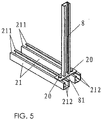
FIG. 5 is a perspective view of the connection between the rail and the bracket in the bracket pedestal of the water pump equipment of the invention; -
FIG. 6 is a sectional view of the connection between a rail and the bracket in a bracket pedestal of the water pump equipment of the invention; and -
FIG. 7 is a perspective view of a water pump equipment provided with two horizontal water pumps in a second embodiment of the invention. - The embodiments of the invention will be described in detail hereinafter. However, it would be noted, the embodiments described here are intended only to illustrate, rather than to limit the scope of the invention.
- As shown in
FIGS. 1-6 , the water pump equipment in the first embodiment of the invention includes a base, threehorizontal water pumps 3 mounted on the base, a water inlet pipeline and a water outlet pipeline. Thehorizontal water pump 3 has a water inlet and a water outlet. - The water inlet pipeline includes three
water inlet components 4 and awater inlet manifold 5. One end of each of the threewater inlet components 4 is connected to the water inlet of each of the three horizontal water pumps, and the other end is communicating with thewater inlet manifold 5. One end or two ends of thewater inlet manifold 5 is/are provided with a connecting structure such as a flange or thread for connecting the water supply network. - The water outlet pipeline includes three
water outlet components 6 and awater outlet manifold 7. Each of the threewater outlet components 6 has one end thereof connected to one of the water outlets of the threehorizontal water pumps 3, and has the other end communicating with thewater outlet manifold 7. One end or two ends of thewater outlet manifold 7 is/are provided with a connecting structure such as a flange or thread for connecting a water supply network. - As shown in
FIGS. 3 and4 , the base includes apump pedestal 1 and twobracket pedestals 2. The threehorizontal water pumps 3 are fixedly mounted on thepump pedestal 1. Thepump pedestal 1 includes two L-shaped side plates 11 which are symmetrically arranged and atop plate 12 which connects the tops of vertical plates of the two L-shaped side plates 11. Thetop plate 12 is provided withseveral screw holes 13. The vertical plate of each L-shaped side plate 11 is provided with two throughholes 14, and twobracket pedestals 2 pass through the corresponding throughholes 14 to extend under thetop plate 12 to be detachably connected to thetop plate 12 of thepump pedestal 1 by bolts or nuts. The bolts may pass throughdifferent screw holes 13 of thetop plate 12 to make an extending length of thebracket pedestal 2 adjustable relative to thepump pedestal 1. Twobrackets 8 are disposed on eachbracket pedestal 2, and the top of eachbracket 8 is provided with a connectingpart 82. The connectingparts 82 of the twobrackets 8 on eachbracket pedestal 2 fixedly support thewater inlet manifold 5 and thewater outlet manifold 7, respectively. - The
bracket pedestal 2 includes afront panel 22 and aback panel 23 disposed opposite to each other, and twoparallel rails 21. Front and back ends of eachrail 21 are fixed to thefront panel 22 and theback panel 23 by welding, respectively. Therail 21 may be provided with a drain hole (not shown) to drain away the water in therail 21. Therail 21 has a U-shaped cross section with two guiding portions oppositely disposed at a top opening of theU-shaped rail 21. Therails 21 are provided therein withnuts 9, and acompression spring 10 is fixed right under each of thenut 9 by welding or other ways. An upper surface of thenut 9 abuts against the guiding portion by means of a pretightening force of thecompression spring 10. A bottom of thebracket 8 is provided with abottom plate 81 which may be structurally integrated into thebracket 8 or fixed to thebracket 8 by welding or other ways. Thebottom plate 81 is provided with two screw holes which are detachably connected to the twonuts 9 in the tworails 21 of thebracket pedestal 2 by thebolts 20. As a result, thebracket 8 may be connected to thebracket pedestal 2 with the length of the end of thebracket 8 being adjustable relative to thebracket pedestal 2. To further improve guiding function, the guiding portion may be designed in structure to include twohorizontal portions 211 which are oppositely disposed and twovertical portions 212 which extend downwardly from the edges of thehorizontal portions 211, respectively, and thenut 9 is provided at its top on both sides with guidingslots 91 slidably fitting with the twovertical portions 212. Thus the guiding is smooth, so that the adjustment of thebracket 8 relative to thebracket pedestal 2 is more convenient. Thebracket pedestal 2 may be provided with only onerail 21 instead, in such a case, thebottom plate 81 of thebracket 8 may be provided with only one screw hole correspondingly. According to the invention, the compression springs 10 with pretightening force can prevent the adjusted nuts 9 from moving easily, and even in case of vibration occurring during operating or transporting, thenuts 9 may still be located at the special positions. - The
pump pedestal 1 is not limited to the above structure and shape, rather, as long as its strength can support the horizontal water pumps 3, thepump pedestal 1 may have other shapes or structures such as a rectangle shape, a case shape, a frame structure or any other available structures suitable for the base. To mount thebracket pedestal 2 and make the extending length of thebracket pedestal 2 adjustable, through holes may be disposed on thepump pedestal 1. If the through holes are disposed transversely along thepump pedestal 1, the layout of pluralities of pumps may be more proper, and the force applied on thepump pedestal 1 may be more uniform. The twobracket pedestals 2 are not limited to have the above structure, rather, it may have other structures such as a flat board. If thebracket pedestal 2 has a flat structure, it can be directly fixed to the upper surface of thepump pedestal 1 by bolts and nuts, and its extending length is adjustable by the screw holes connected at different positions of thepump pedestal 1. - Furthermore, in case the
bracket pedestal 2 is provided withrails 21, thebracket pedestal 2 may also be connected to thepump pedestal 1 by nuts with compression springs. Preferably, eachrail 21 may be provided with two nuts (not shown) for connecting thepump pedestal 1, and the compression springs are disposed under the nuts. The upper surface of the nut abuts against thetop plate 12 of thepump pedestal 1 by means of a pretightening force of the compression spring, and thetop plate 12 is provided with twoscrew holes 13 at position corresponding to eachrail 21. Therefore, thetop plate 12 is provided with fourscrew holes 13 in total at position corresponding to eachbracket pedestal 2, and four bolts (not shown) are connected with the four nuts in the tworails 21 by passing through the fourscrew holes 13 of thetop plate 12. The nuts for connecting thepump pedestal 1 are also provided with guiding portions just as thenuts 9 for connecting thebracket 8. Using the bolts and the nuts with compression springs to connect thebracket pedestal 2 and thepump pedestal 1 can prevent the adjusted nuts from moving easily, and even in case of vibration occurring during operating or transporting, the nuts may still be located at the special positions. Besides, the adjustment between thebracket pedestal 2 and thepump pedestal 1 may be more convenient and precise. - As shown in
FIG. 7 , the water pump equipment in the second embodiment of the invention has a structure generally same as that of the first embodiment with only the following difference: there are two horizontal water pumps 3 and onebracket pedestal 2 in the second embodiment. Therefore, the vertical plate on the L-shapedside plate 11 of thepump pedestal 1 is provided with only one throughhole 14. The rest similar parts will not be illustrated herein for conciseness. - When the water pump equipment in the invention is mounted in the water supply network, the bolts which fasten the
bracket pedestal 2 and thepump pedestal 1 may be released at first, and then the extending length of thebracket pedestal 2 relative to thepump pedestal 1 is adjusted according to specific size of the space, thereby adjusting thewater inlet manifold 5 and thewater outlet manifold 7 to the positions proper for connection with the connecting pipeline of the water supply network. Afterwards, thebracket pedestal 2 is fastened to thepump pedestal 1 by the bolts. As a result, the water pump equipment of the invention would not be limited by various spaces, and it is not necessary to change the whole base, so the trouble to mount the water pump again is avoided, the mounting effect is greatly improved, and the cost is reduced as well. Furthermore, after the water pump equipment in the invention is mounted in the water supply network, if the positions of the pipelines of the water supply network are changed, the user may release thebolts 20 fixed to thebracket 8 to make thebracket 8 drive thewater inlet manifold 5 or thewater outlet manifold 7 to slide to a proper position along therails 21, and tighten thebolts 20 again to fix to thebracket 8. Therefore, even if the positions of the pipelines of the water supply network are changed, what is required for the water pump equipment of the invention is only to properly adjust the positions of thebrackets 8 without replacing the whole water pump equipment and the base, which is convenient and practical. - Although the invention has been described as above in reference to some typical embodiments, it is to be understood that the terms used therein are just illustrative and exemplary rather than restrictive. Since the invention can be applied in various forms without departing from the spirit or principle of the invention, it is to be understood that the above-mentioned embodiments will not be limited to any specific details mentioned above, rather, they should be construed broadly in the spirit or concept of the invention defined by the appended claims. Therefore, the present invention aims to cover all the modifications or variations falling within the protection scope defined by the appended claims.
Claims (11)
- A water pump equipment comprising a base, at least two horizontal water pumps (3) mounted on the base, a water inlet pipeline and a water outlet pipeline, wherein the horizontal water pump (3) is provided with a water inlet and a water outlet; wherein the water inlet pipeline includes at least two water inlet components (4) which are connected to the water inlets of the at least two horizontal water pumps (3), respectively, and a water inlet manifold (5) which is communicating with the at least two water inlet components (4); wherein the water outlet pipeline includes at least two water outlet components (6) which are connected to the water outlets of the at least two horizontal water pumps, respectively, and a water outlet manifold (7) which is communicating with the at least two water outlet components (6); wherein each of the water inlet manifold (5) and the water outlet manifold (7) is supported on the base by a bracket (8); characterized in that the base includes a pump pedestal (1) and at least one bracket pedestal (2), the at least two horizontal water pumps (3) are fixedly mounted on the pump pedestal (1); wherein the bracket (8) is mounted on the bracket pedestal (2); and wherein the bracket pedestal (2) is connected to the pump pedestal (1) with an extending length of the bracket pedestal (2) adjustable relative to the pump pedestal (1).
- The water pump equipment according to claim 1, characterized in that the pump pedestal (1) is provided with at least one through hole (14), and the at least one bracket pedestal (2) is connected to the pump pedestal (1) by passing through the corresponding through hole (14).
- The water pump equipment according to claim 2, characterized in that the through hole is disposed transversely along the pump pedestal (1).
- The water pump equipment according to claim 2, characterized in that the pump pedestal (1) comprises two L-shaped side plates (11) which are symmetrically arranged and a top plate (12) which connects tops of vertical plates of the two L-shaped side plates (11), the through hole (14) is disposed in the vertical plate of each of the two L-shaped side plates (11), and the at least one bracket pedestal (2) is connected to the top plate (12) of the pump pedestal (1).
- The water pump equipment according to any of claims 1 to 4, characterized in that the bracket (8) is connected to the bracket pedestal (2) with an length of the end of the bracket (8) adjustable relative to the bracket pedestal (2).
- The water pump equipment according to claim 5, characterized in that a bottom of the bracket (8) is provided with a bottom plate (81), and the bottom plate (81) is provided with at least one screw hole; wherein the bracket pedestal (2) is provided with at least one rail (21); wherein the rail (21) has a U-shaped cross section with two guiding portions oppositely disposed at a top opening of the U-shaped rail (21); and wherein each of the rails (21) is provided therein with at least one nut (9) for connecting the bottom plate (81), and at least one bolt (20) passes through the least one screw hole on the bottom plate (81) and is connected with the at least one nut (9) in the at least one rail (21).
- The water pump equipment according to claim 6, characterized in that a compression spring (10) is disposed right under each of the nuts (9) for connecting the bottom plate (81), and an upper surface of the nut (9) abuts against the guiding portion by means of a pretightening force of the compression spring (10).
- The water pump equipment according to claim 6, characterized in that the bracket pedestal (2) is provided with two rails (21), the guiding portion of each rail (21) includes two horizontal portions (211) which are oppositely disposed and two vertical portions (212) which extend downwardly from edges of the two horizontal portions (211), respectively, and the nut (9) for connecting the bottom plate (81) of the bracket (8) is provided at top surface on both sides thereof with guiding slots (91) slidably fitting to the two vertical portions (212).
- The water pump equipment according to claim 6, characterized in that the bracket pedestal (2) is provided with two rails (21) each of which is provided therein with at least one nut for connecting the pump pedestal (1), the top plate (12) of the pump pedestal (1) is provided with at least two screw holes (13) at positions corresponding to each rail (21), and at least two bolts connect with the at least two nuts in two rails (21) by passing through the at least two screw holes (13).
- The water pump equipment according to claim 9, characterized in that a compression spring is disposed under each of the nuts for connecting the pump pedestal (1), and an upper surface of the nut abuts against the top plate (12) of the pump pedestal (1) by means of a pretightening force of the compression spring.
- The water pump equipment according to claim 9, characterized in that each of the rails (21) is provided therein with two nuts for connecting the pump pedestal (1), and the pump pedestal (1) is provided with four screw holes (13) at positions corresponding to each bracket pedestal (2).
Applications Claiming Priority (1)
| Application Number | Priority Date | Filing Date | Title |
|---|---|---|---|
| CN2011100433108A CN102072130B (en) | 2011-02-17 | 2011-02-17 | Water pump equipment |
Publications (2)
| Publication Number | Publication Date |
|---|---|
| EP2489790A2 true EP2489790A2 (en) | 2012-08-22 |
| EP2489790A3 EP2489790A3 (en) | 2015-07-08 |
Family
ID=44030824
Family Applications (1)
| Application Number | Title | Priority Date | Filing Date |
|---|---|---|---|
| EP12156023.9A Withdrawn EP2489790A3 (en) | 2011-02-17 | 2012-02-17 | Water pump equipment |
Country Status (2)
| Country | Link |
|---|---|
| EP (1) | EP2489790A3 (en) |
| CN (1) | CN102072130B (en) |
Cited By (8)
| Publication number | Priority date | Publication date | Assignee | Title |
|---|---|---|---|---|
| ITPD20130058A1 (en) * | 2013-03-08 | 2014-09-09 | Dab Pumps Spa | PLINTH FOR PUMPING DEVICES |
| CN110425152A (en) * | 2019-08-20 | 2019-11-08 | 济南金孚瑞供热工程技术有限公司 | A kind of SMART FLUID pump group |
| CN112282438A (en) * | 2020-11-11 | 2021-01-29 | 中铁二十五局集团第五工程有限公司 | Quick-building pumping irrigation station |
| CN112576497A (en) * | 2020-12-11 | 2021-03-30 | 无锡砝莉曼动力机械有限公司 | Water pump set with adjustable conveying direction |
| CN113266607A (en) * | 2021-06-30 | 2021-08-17 | 中国人民解放军海军工程大学 | Marine sea water cooling cycle pump package floating valve vibration isolation structure |
| CN114541518A (en) * | 2022-03-08 | 2022-05-27 | 安徽皖水水务发展有限公司 | Intelligent booster pump station |
| CN116398449A (en) * | 2023-04-12 | 2023-07-07 | 凯泉集团有限公司 | Single-stage horizontal water pump performance test equipment |
| CN118757398A (en) * | 2024-07-05 | 2024-10-11 | 山东淄博德西瑞泵业有限公司 | Improved vacuum pump |
Families Citing this family (4)
| Publication number | Priority date | Publication date | Assignee | Title |
|---|---|---|---|---|
| CN103511217A (en) * | 2012-06-18 | 2014-01-15 | 上海连成(集团)有限公司 | Water supply device for Y type diesel engine pump set |
| CN103671003A (en) * | 2013-12-09 | 2014-03-26 | 高舒林 | Pumping device |
| CN113502876B (en) * | 2021-07-13 | 2022-11-18 | 浙江融乐环境科技有限公司 | Integrated intelligent pump room with intelligent real-time monitoring mechanism |
| CN118407890B (en) * | 2024-06-07 | 2025-03-21 | 江苏岚光能源科技有限公司 | A highly wear-resistant mud pump capable of modular splicing and use method thereof |
Family Cites Families (5)
| Publication number | Priority date | Publication date | Assignee | Title |
|---|---|---|---|---|
| GB8624953D0 (en) * | 1986-10-17 | 1986-11-19 | Action Pumping Services Ltd | Hydro-pneumatic pumpsets |
| JPH0463972A (en) * | 1990-07-02 | 1992-02-28 | Kawamoto Seisakusho:Kk | Pump device |
| JP2000240564A (en) * | 1999-02-22 | 2000-09-05 | Susumu Hotta | Pump unit |
| CN201436542U (en) * | 2009-02-24 | 2010-04-07 | 宝山钢铁股份有限公司 | A water cooling device for heating simulated materials in an experimental furnace |
| CN202023220U (en) * | 2011-02-17 | 2011-11-02 | 格兰富水泵(苏州)有限公司 | Water pump equipment |
-
2011
- 2011-02-17 CN CN2011100433108A patent/CN102072130B/en not_active Expired - Fee Related
-
2012
- 2012-02-17 EP EP12156023.9A patent/EP2489790A3/en not_active Withdrawn
Non-Patent Citations (1)
| Title |
|---|
| None |
Cited By (12)
| Publication number | Priority date | Publication date | Assignee | Title |
|---|---|---|---|---|
| ITPD20130058A1 (en) * | 2013-03-08 | 2014-09-09 | Dab Pumps Spa | PLINTH FOR PUMPING DEVICES |
| EP2775145A1 (en) * | 2013-03-08 | 2014-09-10 | Dab Pumps S.p.A. | Base for pumping devices |
| US9739286B2 (en) | 2013-03-08 | 2017-08-22 | Dab Pumps S.P.A. | Modular storage base for pumping devices |
| CN110425152A (en) * | 2019-08-20 | 2019-11-08 | 济南金孚瑞供热工程技术有限公司 | A kind of SMART FLUID pump group |
| CN112282438A (en) * | 2020-11-11 | 2021-01-29 | 中铁二十五局集团第五工程有限公司 | Quick-building pumping irrigation station |
| CN112576497A (en) * | 2020-12-11 | 2021-03-30 | 无锡砝莉曼动力机械有限公司 | Water pump set with adjustable conveying direction |
| CN112576497B (en) * | 2020-12-11 | 2022-10-21 | 无锡砝莉曼动力机械有限公司 | Water pump set with adjustable conveying direction |
| CN113266607A (en) * | 2021-06-30 | 2021-08-17 | 中国人民解放军海军工程大学 | Marine sea water cooling cycle pump package floating valve vibration isolation structure |
| CN113266607B (en) * | 2021-06-30 | 2022-05-20 | 中国人民解放军海军工程大学 | Vibration isolation structure for floating valve of marine seawater cooling circulating pump set |
| CN114541518A (en) * | 2022-03-08 | 2022-05-27 | 安徽皖水水务发展有限公司 | Intelligent booster pump station |
| CN116398449A (en) * | 2023-04-12 | 2023-07-07 | 凯泉集团有限公司 | Single-stage horizontal water pump performance test equipment |
| CN118757398A (en) * | 2024-07-05 | 2024-10-11 | 山东淄博德西瑞泵业有限公司 | Improved vacuum pump |
Also Published As
| Publication number | Publication date |
|---|---|
| CN102072130A (en) | 2011-05-25 |
| CN102072130B (en) | 2012-07-25 |
| EP2489790A3 (en) | 2015-07-08 |
Similar Documents
| Publication | Publication Date | Title |
|---|---|---|
| EP2489790A2 (en) | Water pump equipment | |
| US11527815B2 (en) | Universal RRU mounting assembly | |
| US20100248610A1 (en) | Adjustable Vertical Exhaust Duct | |
| CN108225697A (en) | For tensing and cooling down the test fixture of article | |
| KR20210123115A (en) | Adsorption device for display panel with variable position and size | |
| TW201409409A (en) | Temperature control system for vending machine | |
| CN105201114A (en) | Anti-bouncing device of curtain wall | |
| CN204633137U (en) | A kind of fixed support | |
| CN216046130U (en) | Dynamic vibration absorber, compressor and air conditioner | |
| CN201113236Y (en) | distribution box | |
| EP2416047B1 (en) | Bed frame for a machine | |
| CN202023220U (en) | Water pump equipment | |
| KR200462781Y1 (en) | An assembly device of a rail | |
| CN208715182U (en) | A kind of rolling stock air damping cabinet device | |
| US20120192964A1 (en) | Fluid control apparatus | |
| CN217158944U (en) | Installation kit and capacitor box | |
| CN207765319U (en) | A kind of coil shaper and its coil clamping plate install base device | |
| CN205583429U (en) | Power distribution for cabinet components and parts install alignment jig | |
| CN102694278B (en) | Quick wire connector | |
| CN210517939U (en) | Motor installation adjusting module | |
| CN208601628U (en) | A kind of cross cutting notch waste clearing device | |
| CN207083344U (en) | A multifunctional device fixing device | |
| CN217873462U (en) | Fan base | |
| KR101115017B1 (en) | Supporting instrument for gate valve | |
| CN205275752U (en) | A wind pipe bracket for electric plate wire |
Legal Events
| Date | Code | Title | Description |
|---|---|---|---|
| PUAI | Public reference made under article 153(3) epc to a published international application that has entered the european phase |
Free format text: ORIGINAL CODE: 0009012 |
|
| AK | Designated contracting states |
Kind code of ref document: A2 Designated state(s): AL AT BE BG CH CY CZ DE DK EE ES FI FR GB GR HR HU IE IS IT LI LT LU LV MC MK MT NL NO PL PT RO RS SE SI SK SM TR |
|
| AX | Request for extension of the european patent |
Extension state: BA ME |
|
| PUAL | Search report despatched |
Free format text: ORIGINAL CODE: 0009013 |
|
| AK | Designated contracting states |
Kind code of ref document: A3 Designated state(s): AL AT BE BG CH CY CZ DE DK EE ES FI FR GB GR HR HU IE IS IT LI LT LU LV MC MK MT NL NO PL PT RO RS SE SI SK SM TR |
|
| AX | Request for extension of the european patent |
Extension state: BA ME |
|
| RIC1 | Information provided on ipc code assigned before grant |
Ipc: E03B 5/02 20060101AFI20150601BHEP |
|
| 17P | Request for examination filed |
Effective date: 20160105 |
|
| RBV | Designated contracting states (corrected) |
Designated state(s): AL AT BE BG CH CY CZ DE DK EE ES FI FR GB GR HR HU IE IS IT LI LT LU LV MC MK MT NL NO PL PT RO RS SE SI SK SM TR |
|
| GRAP | Despatch of communication of intention to grant a patent |
Free format text: ORIGINAL CODE: EPIDOSNIGR1 |
|
| STAA | Information on the status of an ep patent application or granted ep patent |
Free format text: STATUS: GRANT OF PATENT IS INTENDED |
|
| RIC1 | Information provided on ipc code assigned before grant |
Ipc: F04D 13/12 20060101ALI20170726BHEP Ipc: F04B 23/04 20060101ALI20170726BHEP Ipc: E03B 5/02 20060101AFI20170726BHEP Ipc: F04D 29/70 20060101ALI20170726BHEP Ipc: F04B 53/22 20060101ALI20170726BHEP Ipc: F04B 23/02 20060101ALI20170726BHEP |
|
| INTG | Intention to grant announced |
Effective date: 20170816 |
|
| STAA | Information on the status of an ep patent application or granted ep patent |
Free format text: STATUS: THE APPLICATION IS DEEMED TO BE WITHDRAWN |
|
| 18D | Application deemed to be withdrawn |
Effective date: 20180103 |