EP2489285A1 - Hair styling apparatus having selectively adjustable curling component - Google Patents
Hair styling apparatus having selectively adjustable curling component Download PDFInfo
- Publication number
- EP2489285A1 EP2489285A1 EP20120154843 EP12154843A EP2489285A1 EP 2489285 A1 EP2489285 A1 EP 2489285A1 EP 20120154843 EP20120154843 EP 20120154843 EP 12154843 A EP12154843 A EP 12154843A EP 2489285 A1 EP2489285 A1 EP 2489285A1
- Authority
- EP
- European Patent Office
- Prior art keywords
- curling
- hair
- edge
- component
- heating
- Prior art date
- Legal status (The legal status is an assumption and is not a legal conclusion. Google has not performed a legal analysis and makes no representation as to the accuracy of the status listed.)
- Granted
Links
- 238000010438 heat treatment Methods 0.000 claims abstract description 130
- 238000000034 method Methods 0.000 claims description 8
- 238000006073 displacement reaction Methods 0.000 claims description 4
- XEEYBQQBJWHFJM-UHFFFAOYSA-N Iron Chemical compound [Fe] XEEYBQQBJWHFJM-UHFFFAOYSA-N 0.000 description 56
- 229910052742 iron Inorganic materials 0.000 description 28
- 238000001816 cooling Methods 0.000 description 3
- 239000000463 material Substances 0.000 description 3
- 230000006835 compression Effects 0.000 description 2
- 238000007906 compression Methods 0.000 description 2
- 230000000712 assembly Effects 0.000 description 1
- 238000000429 assembly Methods 0.000 description 1
- 230000015572 biosynthetic process Effects 0.000 description 1
- 229910010293 ceramic material Inorganic materials 0.000 description 1
- 239000004020 conductor Substances 0.000 description 1
- 238000010276 construction Methods 0.000 description 1
- 238000003780 insertion Methods 0.000 description 1
- 230000037431 insertion Effects 0.000 description 1
- 239000012212 insulator Substances 0.000 description 1
- 235000000396 iron Nutrition 0.000 description 1
- 239000002184 metal Substances 0.000 description 1
- 229910052751 metal Inorganic materials 0.000 description 1
- -1 without limitation Substances 0.000 description 1
Images




Classifications
-
- A—HUMAN NECESSITIES
- A45—HAND OR TRAVELLING ARTICLES
- A45D—HAIRDRESSING OR SHAVING EQUIPMENT; EQUIPMENT FOR COSMETICS OR COSMETIC TREATMENTS, e.g. FOR MANICURING OR PEDICURING
- A45D1/00—Curling-tongs, i.e. tongs for use when hot; Curling-irons, i.e. irons for use when hot; Accessories therefor
- A45D1/02—Curling-tongs, i.e. tongs for use when hot; Curling-irons, i.e. irons for use when hot; Accessories therefor with means for internal heating, e.g. by liquid fuel
- A45D1/04—Curling-tongs, i.e. tongs for use when hot; Curling-irons, i.e. irons for use when hot; Accessories therefor with means for internal heating, e.g. by liquid fuel by electricity
Definitions
- the present disclosure relates generally to hair styling apparatus, and more particularly to a hair styling apparatus having a selectively adjustable curling component for use in curling hair.
- hair styling apparatus Many different types are available for use in styling hair, such as straightening, curling, waving or otherwise achieving a desired look.
- hair styling apparatus is the ability to apply heat to the hair, and in particular to provide one or more heated surfaces against which the hair to be styled is contacted during styling.
- flat irons which are also sometimes referred to as heated tongs or hair straighteners
- a heating member with a heating surface is provided on at least one of the arms, and more typically on both of the arms. In use, the hair being styled is sandwiched between the heating surfaces of the heating members when the arms are in their closed position.
- the hair may be straightened as a result of the heat and pressure applied by the heating members, or the hair may be curled.
- the flat iron when using the flat iron to curl hair, the flat iron may be manually rotated about its axis. Portions of the hair between the heating plates are heated, and as the flat iron is rotated and moved along the hair, the heated hair wraps over a relatively cooler cooling edge of the flat iron. The hair takes on a curled shape upon cooling of the hair on the cooling edge.
- a hair styling apparatus generally comprises first and second arms each having opposite ends and an imaginary axis extending between the opposite ends.
- the first and second arms are pivotably secured to one another for selective, pivotal movement toward one another to configure the hair styling apparatus in a closed position.
- a heating member on the first arm has a hair-heating surface in generally opposing relationship with the second arm for applying heat to hair between the first and second arms in the closed position of the hair styling apparatus.
- the hair-heating surface has a lateral edge.
- a curling component generally proximate to the hair-heating surface and operatively connected to at least one of the first and second arms has a curling edge selectively movable laterally with respect to the hair-heating surface to configure the curling component between a retracted configuration, in which the curling edge is spaced a retracted lateral distance from the lateral edge of the hair-heating surface, and an extended configuration, in which the curling edge is spaced an extended lateral distance, greater than the retracted lateral distance, from the lateral edge of the hair-heating surface.
- a hair styling apparatus generally comprises first and second arms each having opposite ends and an axis extending between the opposite ends.
- the first and second arms are pivotably secured to one another for selective, pivotal movement toward one another to configure the hair styling apparatus in a closed position.
- First and second heating members on the respective first and second arms for applying heat to hair between the first and second arms in the closed position of the hair styling apparatus have respective hair-heating surfaces in generally opposing relationship with one another.
- Each hair-heating surface has a lateral edge.
- a first curling component is operatively connected to the first arm and has a curling edge.
- the curling edge of the first curling component is selectively movable laterally with respect to the hair-heating surface of the first heating member to configure the first curling component between a retracted configuration, in which the curling edge of the first curling component is spaced a retracted lateral distance from the lateral edge of the hair-heating surface of the first heating member, and an extended configuration, in which the curling edge of the first curling component is spaced an extended lateral distance, greater than the retracted lateral distance, from the lateral edge of the hair-heating surface of the first heating member.
- a second curling component is operatively connected to the second arm and has a curling edge.
- the curling edge of the second curling component is selectively movable laterally with respect to the hair-heating surface of the second heating member to configure the second curling component between a retracted configuration, in which the curling edge of the second curling component is spaced a retracted lateral distance from the lateral edge of the hair-heating surface of the second heating member, and an extended configuration, in which the curling edge of the second curling component is spaced an extended lateral distance, greater than the retracted lateral distance, from the lateral edge of the hair-heating surface of the second heating member.
- a method of styling hair using a hair styling apparatus of the type including first and second arms that are pivotably secured to one another for selective, pivotal movement toward one another to close the hair styling apparatus, and first and second heating members on the respective first and second arms having respective hair-heating surfaces with respective lateral edges, generally comprises adjusting a lateral distance between a curling edge of a curling component of the hair styling apparatus and at the lateral edge of the first heating member to configure the curling component in a selected one of a plurality of different configurations. Hair is disposed between the hair-heating surfaces of the first and second heating members, and the hair is curled using the curling edge of the curling component.
- FIG. 1 is a perspective of a hair styling apparatus having selectively adjustable curling components, the hair styling apparatus being in a closed position;
- FIG. 2 is a perspective of the hair styling apparatus of FIG. 2 with the hair styling apparatus in an open position;
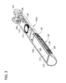
- FIG. 3 is a perspective of a first arm of the hair styling apparatus, a second arm being removed therefrom;
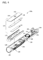
- FIG. 4 is a perspective of the first arm of FIG. 3 with a heating member assembly exploded therefrom;
- FIG. 5 is a partial perspective of the first arm of FIG. 3 with a curling component exploded therefrom;
- FIG. 6 is a partial top plan view of the first arm of FIG. 3 with a portion removed to show a locking mechanism of the curling component, the curling component being in a retracted configuration;
- FIG. 7 is similar to FIG. 6 except the curling component is in an intermediate configuration
- FIG. 8 is similar to FIG. 6 except the curling component is in an extended configuration
- FIG. 9 is a bottom plan view of the first arm of FIG. 6 ;
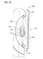
- FIG. 10 is a bottom plan view of the first arm of FIG. 8 .
- the illustrated hair styling apparatus 101 is generally in the form of a flat iron (also referred to as a hair straightener), which can be used to straighten and curl hair.
- the hair styling apparatus 101 comprises two hair curling components, generally indicated at 150, 152, for use in curling hair using the apparatus.
- the hair curling components 150, 152 are selectively adjustable to allow a user to selectively adjust curl size and/or curl tightness of the hair to a desired curl size and/or a desired curl tightness.
- the hair styling apparatus 101 may be of a different type, other than a flat iron, such as a curling iron or other suitable type of hair styling apparatus that is adapted to heat hair and facilitate curling of the hair. It is also contemplated that in other embodiments the hair styling apparatus 101 may include one, or more than two, hair curling components.
- the flat iron 101 is generally elongate with opposite longitudinal ends and has first and second arms (lower and upper arms as illustrated in FIGS. 1 and 2 ), generally indicated at 103a and 103b, respectively, held in assembly with each other by a suitable pivot connection 104 at one of the longitudinal ends of the flat iron.
- the first and second arms 103a, 103b are thus moveable relative to one another and about a pivot axis of the pivot connection 104 between an open position ( FIG. 1 ) of the flat iron 101 and a closed position ( FIG. 2 ) thereof.
- a biasing member in the form of a compression spring 105 ( FIG. 3 ) is suitably positioned between the first and second arms 103a, 103b adjacent to the pivot connection 104.
- the spring 105 is seated within opposed spring seats 106 (one of which is illustrated in FIGS. 3 and 4 ) formed on each arm to urge the arms toward the open position of the flat iron 101.
- the first arm comprises an outer shell or housing member 109 having an interior space in which various components of the flat iron are located.
- a suitable control system for controlling operation of the flat iron (such as power on/off and/or heat output control).
- the control system is electrically connected to a suitable power source (not shown) via an electrical cord 108 ( FIGS. 1 and 2 ) that is connected to the flat iron 101 rearward of the pivot connection 104, and by suitable internal wiring (not shown) between the cord and the control system.
- a suitable switch 121 and in particular a rotatable dial in the illustrated embodiment, is accessible exterior of the first arm 103a and is useable by the user to operate the control system of the flat iron 101.
- switch 121 and control system are located on the first arm 103a of the flat iron 101, it is understood that the switch and control system may instead be located on the second arm 103b of the flat iron. It is also contemplated that separate switches may be provided, one for power on/off and another for controlling the heat output, or that a single power on/off switch may be provided without the ability to control the heat output, and remain within the scope of this invention. Other configurations are also possible and do not depart from the scope of the present invention.
- a cradle insert 113 seats within the interior space of the housing member 109 and forms a cradle in which a heating member assembly 114, is seated and secured.
- the heating member assembly 114 comprises a heating member 111, which is in the form of a generally rectangular plate in the illustrated embodiment, a heating unit 117 disposed within the housing member and electrically connected to the control system via suitable wiring (not shown), and a temperature sensing unit 119, which may include a thermistor electrically connected to the control system, and heat conductor in thermal contact with the heating unit.
- the heating unit 117 suitably comprises one or more heaters, such as electrical resistance heaters (e.g., PTC heating units), positioned in contact with or in sufficiently close proximity to the heating member 111 to heat the heating member during use of the flat iron 101.
- the heating unit 117 is operable to heat the heating member 111 to a styling temperature of at least about 100 degrees Celsius, and may heat the heating member up to a temperature of about 250 degrees Celsius.
- the heating unit 117 is operable to heat the heating member 111 to a styling temperature in the range of about 180 to about 230 degrees Celsius. It is understood that other suitable heating units or heating methods may be used to heat the heating member 111 without departing from the scope of this invention.
- the heating member 111 of the illustrated embodiment is generally rectangular and sized to seat at least partially within the cradle insert 113.
- the heating member 111 has an exposed hair-heating surface 125 opposing the second arm 103b of the flat iron 101.
- the hair-heating surface 125 has opposite lateral edges 126.
- the lateral edges 126 are spaced laterally inward from respective adjacent lateral edges 128 of the housing 109 of the first arm 103a.
- the hair-heating surface 125 and lateral edges 126 are disposed above the lateral edges 128 of the housing.
- another component such as a thermal insulator, may be disposed on the hair-heating surface 125.
- the heating member 111 may be constructed of any suitable material, such as, without limitation, metal, ceramic materials or combinations thereof as is known in the art.
- the heating member 111 may be of other configurations, including other shapes and sizes, without departing from the scope of the present invention.
- the second arm is constructed substantially similar to the first arm 103a.
- the second arm 103b comprises an outer shell or housing member 129 that generally defines an interior space in which various components of the flat iron are located.
- a second heating member assembly (not shown) is carried by the second arm 103b of the flat iron 101 and is constructed substantially similar to the heating member assembly 114 carried by the first arm 103a.
- the heating member of the second heating member assembly has a hair-heating surface generally opposing the first arm 103a, and more particularly, the hair-heating surface 125 of the first hair heating member 111.
- the hair-heating surface has opposite lateral edges, similar to the first hair-heating surface 125.
- the heating members 111 of the respective heating member assemblies 114 of the first and second arms 103a, 103b are sufficiently located longitudinally on the respective arms so that in the closed position of the flat iron 101, the hair-heating surfaces 125 sandwich and compress hair therebetween. In the open position of the flat iron 101, the hair-facing surfaces 125 of the heating members 111 are spaced apart from one another a sufficient distance to allow the introduction of hair between the hair-facing surfaces.
- the first and second curling components 150, 152 are generally proximate to the respective hair-heating surfaces 125 of the first and second heating members 111, and are operatively secured to the respective first and second arms 103a, 103b to allow selective displacement of the curling components 150, 152 relative to the respective arms, as explained in more detail below.
- the illustrated first and second curling components 150, 152 are substantially identical, and therefore, for ease of explanation, only the first curling component will be described in detail herein, with the understanding that the features of the first curling component apply equally to the second curling component.
- the flat iron 101 may comprise only one or more than two adjustable curling components without departing from the scope of the present invention. It is further understood that other embodiments may include two or more curling components that are not substantially identical to each other.
- the illustrated first curling component 150 comprises a body 154 defining a curling edge 156 that is disposed laterally outward from an adjacent one of the lateral edges 126 of the heating surface 125 of the first heating member 111.
- the illustrated curling edge 156 extends along a substantially linear axis, generally parallel to the axis of the first arm 103a, and lies in a lateral plane that is generally parallel to and offset from (e.g., below) the heating surface 125 of the heating member 111.
- the curling edge 156 may extend along a non-linear path (e.g., a curved path), and/or the curling edge may be other than parallel to the axis of the first arm 103a without departing from the scope of the present invention. At least the curling edge 156, and in the illustrated embodiment the entire body 154, remains at a temperature less than the temperature of the heating member 111.
- the body 154 or at least the curling edge 156 may be formed from material that is substantially thermally non-conductive or may be substantially thermally insulated from the heating member 111 and the heating unit 117 such that the curling edge remains at a temperature less than the temperature of the heating member in use.
- the curling component 150 may be formed from a suitable plastic or from other suitable material.
- the curling component 150 is operatively connected to the first arm 103a such that the body 154 and thus the curling edge 156 are selectively movable laterally with respect to the adjacent lateral edge 126 of the first heating member 111,
- the body 154 is selectively movable along a substantially linear path that is substantially orthogonal to both the axis of the first arm 103a and the axis of the curling edge 156.
- the body 154 may be movable laterally outward from the first arm 103a along a non-linear path (e.g., a curved path) such that the curling edge 156 translates along a non-linear path.
- the curling component 150 may be hingedly secured to the first arm 103a such that the curling edge 156 moves along (i.e., rotates about) an arcuate path.
- the curling edge 156 is selectively movable laterally with respect to the adjacent lateral edge 126 of the first heating member 111.
- the curling edge 156 may be movable along an arcuate path extending alongside the first arm 103a and still be movable laterally with respect to the adjacent lateral edge 126 of the first heating member 111.
- Other ways of making the curling component 150, and in particular the curling edge 156, selectively movable laterally with respect to the adjacent lateral edge 126 of the first heating member 111 are within the scope of the present invention.
- the curling edge 156 is movable relative to the first arm 103a to configure the curling component 150 between a retracted configuration ( FIGS. 1-4 , 6 and 9 ), in which the curling edge is spaced a retracted distance D1 ( FIG. 6 ) from the lateral edge 126 of the heating surface 125; and an extended configuration ( FIGS. 8 and 10 ), in which the curling edge is spaced an extended lateral distance D2 ( FIG. 8 ), greater than the retracted lateral distance D1, from the lateral edge of the heating surface; and at least one intermediate configuration ( FIG.
- the curling component 150 is selectively configurable to a single intermediate configuration, in other embodiments the curling component may be selectively configurable to more than one intermediate configuration, Moreover, in yet another embodiment the curling component 150 may be selectively configurable only between retracted and extended configurations.
- the curling component 150 further comprises a pair of telescoping arms 160 extending outward from an inner surface of the body 154 and slidably connected to the first arm 103a. More specifically, the telescoping arms 160 are slidably received in channels 162 in the first arm 103a.
- the telescoping arms 160 support the body 154 of the curling component 150 as the body is moved relative to the first arm, and facilitate moving the body along a linear, lateral path.
- Other ways of supporting the body 154 on the first arm 103a and facilitating movement of the body and/or the curling edge 156 relative to the lateral edge 126 of the heating member 111 do not depart from the scope of the present invention.
- a locking mechanism 166 operatively connects the curling component 150 to the first arm 103a and facilitates selective locking and unlocking of the curling component in the respective retracted, extended, and intermediate configurations.
- the locking mechanism 166 includes a locking pin 168 on the curling component 150 that is selectively slidable relative to the first arm 103a between a plurality (e.g., three) of spaced apart locking slots 170 defined by the first arm.
- Each of the locking slots 170 corresponds to one of the respective retracted, extended and intermediate configurations of the curling component
- the locking pin 168 is selectively slidable into and out of engagement with the locking slots 170 to adjust the lateral displacement of the curling edge 156 relative to the lateral edge 126 of the hair-heating surface 125.
- the locking pin 168 is resiliently biased and urged toward the locking slots 170 by a spring member 172 (e.g., a compression spring) to inhibit the locking pin from inadvertently disengaging (i.e., withdrawing) from the corresponding locking slot in which it is received.
- the curling component 150 is movable to discrete intervals of displacement relative to the lateral edge 126 of the hair-heating surface 125.
- the locking mechanism 166 may be of other configurations without departing from the scope of the present invention.
- the locking mechanism may be configured to allow the curling component 150 to be movable to an infinite number of intermediate configurations.
- the locking mechanism 166 is secured to the first arm 103a by an attachment member 173 extending laterally outward from the locking pin 168.
- the attachment member 173 is secured to the locking pin 168 by a fastening ring 174, although the attachment member may be secured to the locking pin in other ways and may be formed integrally therewith.
- the attachment member 173 also functions as an anti-rotation device. Upon insertion of the locking pin 168 into a selected one of the locking slots 170, the attachment member 173 slides into a respective one of a plurality of anti-rotation slots 178 formed in the first arm 103a. Each of the anti-rotation slots 178 is aligned with a respective one of the locking slots 170. Through this configuration, the attachment member 173 inhibits rotation of the curling component 150 during use. It is understood that the locking mechanism may be secured to the first arm 103a in other ways without departing from the scope of the present invention.
- An actuator in the form of a slidable button 180 on the exterior surface of the first arm 103a, is operatively connected to the pin 168.
- the button 180 is manually operable, although it is contemplated the actuator may be automatically operable, such as by a motor.
- the button 180 is slidable relative to the first arm 103a in a direction opposite the biasing force of the spring member 172 to selectively move the pin 168 out of the corresponding slot and unlock the curling component 150.
- the body 154 of the curling component 150 can be moved laterally, as discussed above, whereby the pin moves within a slot-connecting track 182 that extends perpendicular to and connects the slots.
- the pin 168 and the anti-rotation member 173 are urged into the corresponding locking slot 170 and anti-rotation slot 178 under the force of the spring member 172, thereby temporarily locking the curling component in the selected configuration.
- the illustrated curling component 150 includes a plurality of teeth 184 that are spaced apart from one another along the body 154 of the curling component and extend partially around the body.
- the teeth 184 extend from the curling edge 156 such that the curling edge is formed as a comb.
- Other ways of forming the curling edge as a comb do not depart from the scope of the present invention.
- the teeth 184 and the illustrated curling edge 156 inhibit hair from sliding and bunching up along the curling edge 156 and the exterior surface of the body 154 when curling hair using the curling component 150.
- the curling component 150 may not include the teeth 184 and/or the curling edge 156 may not be formed as a comb without departing from the scope of the present invention.
- one or both of the curling edge 156 and the exterior surface of the body 154 may be substantially smooth or may have other surface contours.
- the body 154 of the curling component 150 is received in a recess 188 formed in the exterior surface of the first arm 103a when the curling component is configured in its retracted configuration.
- the body 154 of the curling component 150 is substantially commensurate in size and shape with the recess 160 such that an exterior surface of the body 154 visually appears to be integral with the exterior surface of the housing member 109 of the first arm 103a when the curling component is configured in its retracted configuration.
- the curling edge 156 is substantially aligned (i.e., coaxial) with the lateral edge 128 of the first arm 103a.
- the exterior surface of the body 154 is generally arcuate and, when in the retracted configuration, extends transversely and partially around the housing member 109 from adjacent to one of the lateral edges 126 of the housing member 109 to a location intermediate the two lateral edges. In the extended and intermediate configurations, the body 154 of the curling component 150 is at least partially removed from the recess 160.
- the flat iron 101 may be used to either straighten or curl hair.
- the user selects one of the retracted, expanded and intermediate configurations of the curling component 150 and makes any necessary adjustments of the curling component by sliding the button 180 to unlock the curling component and telescopingly slide the curling component laterally relative to the first arm 103a.
- the respective configurations of the curling component 150 facilitate the formation of different types of curls having different sizes and/or different tightness due to the differences in the lateral distances D1, D2, D3 from the lateral edge 126 of the hair-heating surface 125 to the curling edge 156 in the respective retracted, extended and intermediate configurations of the curling component.
- the user may configure the curling component 150 into the retracted configuration, and then use the curling component to curl the hair.
- the user may configure the curling component 150 into the extended configuration, and then use the curling component to curl the hair.
- the user may configure the curling component 150 into the intermediate configuration (or one of the intermediate configurations where there are more than one intermediate configurations), and then use the curling component to curl the hair.
Landscapes
- Hair Curling (AREA)
Abstract
Description
- The present disclosure relates generally to hair styling apparatus, and more particularly to a hair styling apparatus having a selectively adjustable curling component for use in curling hair.
- Many different types of hair styling apparatus are available for use in styling hair, such as straightening, curling, waving or otherwise achieving a desired look. Common among such hair styling apparatus is the ability to apply heat to the hair, and in particular to provide one or more heated surfaces against which the hair to be styled is contacted during styling. For example, flat irons (which are also sometimes referred to as heated tongs or hair straighteners) often have a pair of arms that are moveable relative to one another between a closed position, in which at least portions of the arms are in close proximity to one another to hold hair therebetween, and an open position, in which the arms are spaced from one other such that the arms are generally inoperative to hold hair. A heating member with a heating surface is provided on at least one of the arms, and more typically on both of the arms. In use, the hair being styled is sandwiched between the heating surfaces of the heating members when the arms are in their closed position.
- The hair may be straightened as a result of the heat and pressure applied by the heating members, or the hair may be curled. In particular, when using the flat iron to curl hair, the flat iron may be manually rotated about its axis. Portions of the hair between the heating plates are heated, and as the flat iron is rotated and moved along the hair, the heated hair wraps over a relatively cooler cooling edge of the flat iron. The hair takes on a curled shape upon cooling of the hair on the cooling edge.
- In one aspect, a hair styling apparatus generally comprises first and second arms each having opposite ends and an imaginary axis extending between the opposite ends. The first and second arms are pivotably secured to one another for selective, pivotal movement toward one another to configure the hair styling apparatus in a closed position. A heating member on the first arm has a hair-heating surface in generally opposing relationship with the second arm for applying heat to hair between the first and second arms in the closed position of the hair styling apparatus. The hair-heating surface has a lateral edge. A curling component generally proximate to the hair-heating surface and operatively connected to at least one of the first and second arms has a curling edge selectively movable laterally with respect to the hair-heating surface to configure the curling component between a retracted configuration, in which the curling edge is spaced a retracted lateral distance from the lateral edge of the hair-heating surface, and an extended configuration, in which the curling edge is spaced an extended lateral distance, greater than the retracted lateral distance, from the lateral edge of the hair-heating surface.
- In another aspect, a hair styling apparatus generally comprises first and second arms each having opposite ends and an axis extending between the opposite ends. The first and second arms are pivotably secured to one another for selective, pivotal movement toward one another to configure the hair styling apparatus in a closed position. First and second heating members on the respective first and second arms for applying heat to hair between the first and second arms in the closed position of the hair styling apparatus have respective hair-heating surfaces in generally opposing relationship with one another. Each hair-heating surface has a lateral edge. A first curling component is operatively connected to the first arm and has a curling edge. The curling edge of the first curling component is selectively movable laterally with respect to the hair-heating surface of the first heating member to configure the first curling component between a retracted configuration, in which the curling edge of the first curling component is spaced a retracted lateral distance from the lateral edge of the hair-heating surface of the first heating member, and an extended configuration, in which the curling edge of the first curling component is spaced an extended lateral distance, greater than the retracted lateral distance, from the lateral edge of the hair-heating surface of the first heating member. A second curling component is operatively connected to the second arm and has a curling edge. The curling edge of the second curling component is selectively movable laterally with respect to the hair-heating surface of the second heating member to configure the second curling component between a retracted configuration, in which the curling edge of the second curling component is spaced a retracted lateral distance from the lateral edge of the hair-heating surface of the second heating member, and an extended configuration, in which the curling edge of the second curling component is spaced an extended lateral distance, greater than the retracted lateral distance, from the lateral edge of the hair-heating surface of the second heating member.
- In yet another aspect, a method of styling hair using a hair styling apparatus of the type including first and second arms that are pivotably secured to one another for selective, pivotal movement toward one another to close the hair styling apparatus, and first and second heating members on the respective first and second arms having respective hair-heating surfaces with respective lateral edges, generally comprises adjusting a lateral distance between a curling edge of a curling component of the hair styling apparatus and at the lateral edge of the first heating member to configure the curling component in a selected one of a plurality of different configurations. Hair is disposed between the hair-heating surfaces of the first and second heating members, and the hair is curled using the curling edge of the curling component.
-
FIG. 1 is a perspective of a hair styling apparatus having selectively adjustable curling components, the hair styling apparatus being in a closed position; -
FIG. 2 is a perspective of the hair styling apparatus ofFIG. 2 with the hair styling apparatus in an open position; -
FIG. 3 is a perspective of a first arm of the hair styling apparatus, a second arm being removed therefrom; -
FIG. 4 is a perspective of the first arm ofFIG. 3 with a heating member assembly exploded therefrom; -
FIG. 5 is a partial perspective of the first arm ofFIG. 3 with a curling component exploded therefrom; -
FIG. 6 is a partial top plan view of the first arm ofFIG. 3 with a portion removed to show a locking mechanism of the curling component, the curling component being in a retracted configuration; -
FIG. 7 is similar toFIG. 6 except the curling component is in an intermediate configuration; -
FIG. 8 is similar toFIG. 6 except the curling component is in an extended configuration; -
FIG. 9 is a bottom plan view of the first arm ofFIG. 6 ; and -
FIG. 10 is a bottom plan view of the first arm ofFIG. 8 . - Corresponding reference characters indicate corresponding parts throughout the drawings.
- Referring now to the drawings and in particular to
FIGS. 1 and2 , one embodiment of a hair styling apparatus according to the present invention is generally designated 101. The illustratedhair styling apparatus 101 is generally in the form of a flat iron (also referred to as a hair straightener), which can be used to straighten and curl hair. As explained in more detail below, thehair styling apparatus 101 comprises two hair curling components, generally indicated at 150, 152, for use in curling hair using the apparatus. Thehair curling components hair styling apparatus 101 may be of a different type, other than a flat iron, such as a curling iron or other suitable type of hair styling apparatus that is adapted to heat hair and facilitate curling of the hair. It is also contemplated that in other embodiments thehair styling apparatus 101 may include one, or more than two, hair curling components. - The
flat iron 101 is generally elongate with opposite longitudinal ends and has first and second arms (lower and upper arms as illustrated inFIGS. 1 and2 ), generally indicated at 103a and 103b, respectively, held in assembly with each other by asuitable pivot connection 104 at one of the longitudinal ends of the flat iron. The first andsecond arms pivot connection 104 between an open position (FIG. 1 ) of theflat iron 101 and a closed position (FIG. 2 ) thereof. A biasing member in the form of a compression spring 105 (FIG. 3 ) is suitably positioned between the first andsecond arms pivot connection 104. In particular, thespring 105 is seated within opposed spring seats 106 (one of which is illustrated inFIGS. 3 and4 ) formed on each arm to urge the arms toward the open position of theflat iron 101. - With particular reference to the
first arm 103a of theflat iron 101 as illustrated inFIGS. 2-4 , the first arm comprises an outer shell orhousing member 109 having an interior space in which various components of the flat iron are located. For example, longitudinally adjacent to thespring seat 106 is anaccess panel 110 on the exterior surface that together with thehousing member 109 of thefirst arm 103a encloses a suitable control system (not shown) for controlling operation of the flat iron (such as power on/off and/or heat output control). The control system is electrically connected to a suitable power source (not shown) via an electrical cord 108 (FIGS. 1 and2 ) that is connected to theflat iron 101 rearward of thepivot connection 104, and by suitable internal wiring (not shown) between the cord and the control system. Asuitable switch 121, and in particular a rotatable dial in the illustrated embodiment, is accessible exterior of thefirst arm 103a and is useable by the user to operate the control system of theflat iron 101. - While in the illustrated embodiment the
switch 121 and control system are located on thefirst arm 103a of theflat iron 101, it is understood that the switch and control system may instead be located on thesecond arm 103b of the flat iron. It is also contemplated that separate switches may be provided, one for power on/off and another for controlling the heat output, or that a single power on/off switch may be provided without the ability to control the heat output, and remain within the scope of this invention. Other configurations are also possible and do not depart from the scope of the present invention. - Referring to
FIG. 4 , a cradle insert 113 seats within the interior space of thehousing member 109 and forms a cradle in which aheating member assembly 114, is seated and secured. Theheating member assembly 114 comprises aheating member 111, which is in the form of a generally rectangular plate in the illustrated embodiment, aheating unit 117 disposed within the housing member and electrically connected to the control system via suitable wiring (not shown), and atemperature sensing unit 119, which may include a thermistor electrically connected to the control system, and heat conductor in thermal contact with the heating unit. - The
heating unit 117 suitably comprises one or more heaters, such as electrical resistance heaters (e.g., PTC heating units), positioned in contact with or in sufficiently close proximity to theheating member 111 to heat the heating member during use of theflat iron 101. For example, in one suitable embodiment theheating unit 117 is operable to heat theheating member 111 to a styling temperature of at least about 100 degrees Celsius, and may heat the heating member up to a temperature of about 250 degrees Celsius. In another embodiment theheating unit 117 is operable to heat theheating member 111 to a styling temperature in the range of about 180 to about 230 degrees Celsius. It is understood that other suitable heating units or heating methods may be used to heat theheating member 111 without departing from the scope of this invention. - The
heating member 111 of the illustrated embodiment is generally rectangular and sized to seat at least partially within thecradle insert 113. Theheating member 111 has an exposed hair-heating surface 125 opposing thesecond arm 103b of theflat iron 101. The hair-heating surface 125 has opposite lateral edges 126. In the illustrated embodiment, thelateral edges 126 are spaced laterally inward from respective adjacentlateral edges 128 of thehousing 109 of thefirst arm 103a. Also in the illustrated embodiment, the hair-heating surface 125 andlateral edges 126 are disposed above thelateral edges 128 of the housing. It is understood that another component, such as a thermal insulator, may be disposed on the hair-heating surface 125. Theheating member 111 may be constructed of any suitable material, such as, without limitation, metal, ceramic materials or combinations thereof as is known in the art. Theheating member 111 may be of other configurations, including other shapes and sizes, without departing from the scope of the present invention. - With particular reference to the second or
upper arm 103b of theflat iron 101 as illustrated inFIGS. 1 and2 , the second arm is constructed substantially similar to thefirst arm 103a. Generally, thesecond arm 103b comprises an outer shell orhousing member 129 that generally defines an interior space in which various components of the flat iron are located. A second heating member assembly (not shown) is carried by thesecond arm 103b of theflat iron 101 and is constructed substantially similar to theheating member assembly 114 carried by thefirst arm 103a. In general, the heating member of the second heating member assembly has a hair-heating surface generally opposing thefirst arm 103a, and more particularly, the hair-heating surface 125 of the firsthair heating member 111. The hair-heating surface has opposite lateral edges, similar to the first hair-heating surface 125. - The
heating members 111 of the respectiveheating member assemblies 114 of the first andsecond arms flat iron 101, the hair-heating surfaces 125 sandwich and compress hair therebetween. In the open position of theflat iron 101, the hair-facingsurfaces 125 of theheating members 111 are spaced apart from one another a sufficient distance to allow the introduction of hair between the hair-facing surfaces. - Referring to
FIGS. 1 and2 , the first andsecond curling components heating surfaces 125 of the first andsecond heating members 111, and are operatively secured to the respective first andsecond arms components different arms second curling components flat iron 101 may comprise only one or more than two adjustable curling components without departing from the scope of the present invention. It is further understood that other embodiments may include two or more curling components that are not substantially identical to each other. - As seen best in
FIG. 3 , the illustrated first curlingcomponent 150 comprises abody 154 defining a curlingedge 156 that is disposed laterally outward from an adjacent one of thelateral edges 126 of theheating surface 125 of thefirst heating member 111. The illustratedcurling edge 156 extends along a substantially linear axis, generally parallel to the axis of thefirst arm 103a, and lies in a lateral plane that is generally parallel to and offset from (e.g., below) theheating surface 125 of theheating member 111. It is contemplated that the curlingedge 156 may extend along a non-linear path (e.g., a curved path), and/or the curling edge may be other than parallel to the axis of thefirst arm 103a without departing from the scope of the present invention. At least the curlingedge 156, and in the illustrated embodiment theentire body 154, remains at a temperature less than the temperature of theheating member 111. For example, thebody 154 or at least the curlingedge 156 may be formed from material that is substantially thermally non-conductive or may be substantially thermally insulated from theheating member 111 and theheating unit 117 such that the curling edge remains at a temperature less than the temperature of the heating member in use. The curlingcomponent 150 may be formed from a suitable plastic or from other suitable material. - As explained in more detail below, the curling
component 150 is operatively connected to thefirst arm 103a such that thebody 154 and thus the curlingedge 156 are selectively movable laterally with respect to the adjacentlateral edge 126 of thefirst heating member 111, Thebody 154 is selectively movable along a substantially linear path that is substantially orthogonal to both the axis of thefirst arm 103a and the axis of the curlingedge 156. In another embodiment, thebody 154 may be movable laterally outward from thefirst arm 103a along a non-linear path (e.g., a curved path) such that the curlingedge 156 translates along a non-linear path. For example, the curlingcomponent 150 may be hingedly secured to thefirst arm 103a such that the curlingedge 156 moves along (i.e., rotates about) an arcuate path. In this example, the curlingedge 156 is selectively movable laterally with respect to the adjacentlateral edge 126 of thefirst heating member 111. In another example, the curlingedge 156 may be movable along an arcuate path extending alongside thefirst arm 103a and still be movable laterally with respect to the adjacentlateral edge 126 of thefirst heating member 111. Other ways of making the curlingcomponent 150, and in particular the curlingedge 156, selectively movable laterally with respect to the adjacentlateral edge 126 of thefirst heating member 111 are within the scope of the present invention. - In particular, in the illustrated embodiment the curling
edge 156 is movable relative to thefirst arm 103a to configure thecurling component 150 between a retracted configuration (FIGS. 1-4 ,6 and9 ), in which the curling edge is spaced a retracted distance D1 (FIG. 6 ) from thelateral edge 126 of theheating surface 125; and an extended configuration (FIGS. 8 and10 ), in which the curling edge is spaced an extended lateral distance D2 (FIG. 8 ), greater than the retracted lateral distance D1, from the lateral edge of the heating surface; and at least one intermediate configuration (FIG. 7 ), in which the curling edge is spaced an intermediate lateral distance D3, intermediate the retracted and extended lateral distances, from the lateral edge of the heating surface. In one non-limiting example, the retracted lateral distance D1 may measure from about 0 mm to about 6 mm, and in one example, about 4 mm; the extended lateral distance D2 may measure from about 10 mm to about 20 mm, and in one example, about 16 mm; and one of the intermediate lateral distances D3 may measure from about 5 mm to about 15 mm, and in one example, about 10 mm. Although in the illustrated embodiment the curlingcomponent 150 is selectively configurable to a single intermediate configuration, in other embodiments the curling component may be selectively configurable to more than one intermediate configuration, Moreover, in yet another embodiment the curlingcomponent 150 may be selectively configurable only between retracted and extended configurations. - In the illustrated embodiment, the curling
component 150 further comprises a pair oftelescoping arms 160 extending outward from an inner surface of thebody 154 and slidably connected to thefirst arm 103a. More specifically, thetelescoping arms 160 are slidably received inchannels 162 in thefirst arm 103a. Thetelescoping arms 160 support thebody 154 of the curlingcomponent 150 as the body is moved relative to the first arm, and facilitate moving the body along a linear, lateral path. Other ways of supporting thebody 154 on thefirst arm 103a and facilitating movement of the body and/or the curlingedge 156 relative to thelateral edge 126 of theheating member 111 do not depart from the scope of the present invention. - A
locking mechanism 166 operatively connects the curlingcomponent 150 to thefirst arm 103a and facilitates selective locking and unlocking of the curling component in the respective retracted, extended, and intermediate configurations. Thelocking mechanism 166 includes alocking pin 168 on thecurling component 150 that is selectively slidable relative to thefirst arm 103a between a plurality (e.g., three) of spaced apart lockingslots 170 defined by the first arm. Each of the lockingslots 170 corresponds to one of the respective retracted, extended and intermediate configurations of the curling component, In particular, the lockingpin 168 is selectively slidable into and out of engagement with the lockingslots 170 to adjust the lateral displacement of the curlingedge 156 relative to thelateral edge 126 of the hair-heating surface 125. Thelocking pin 168 is resiliently biased and urged toward the lockingslots 170 by a spring member 172 (e.g., a compression spring) to inhibit the locking pin from inadvertently disengaging (i.e., withdrawing) from the corresponding locking slot in which it is received. Thus, in the illustrated embodiment the curlingcomponent 150 is movable to discrete intervals of displacement relative to thelateral edge 126 of the hair-heating surface 125. Thelocking mechanism 166 may be of other configurations without departing from the scope of the present invention. For example, the locking mechanism may be configured to allow thecurling component 150 to be movable to an infinite number of intermediate configurations. - In the illustrated embodiment, the
locking mechanism 166 is secured to thefirst arm 103a by anattachment member 173 extending laterally outward from the lockingpin 168. Theattachment member 173 is secured to thelocking pin 168 by afastening ring 174, although the attachment member may be secured to the locking pin in other ways and may be formed integrally therewith. Theattachment member 173 also functions as an anti-rotation device. Upon insertion of thelocking pin 168 into a selected one of the lockingslots 170, theattachment member 173 slides into a respective one of a plurality ofanti-rotation slots 178 formed in thefirst arm 103a. Each of theanti-rotation slots 178 is aligned with a respective one of the lockingslots 170. Through this configuration, theattachment member 173 inhibits rotation of the curlingcomponent 150 during use. It is understood that the locking mechanism may be secured to thefirst arm 103a in other ways without departing from the scope of the present invention. - An actuator, in the form of a
slidable button 180 on the exterior surface of thefirst arm 103a, is operatively connected to thepin 168. Thebutton 180 is manually operable, although it is contemplated the actuator may be automatically operable, such as by a motor. Thebutton 180 is slidable relative to thefirst arm 103a in a direction opposite the biasing force of thespring member 172 to selectively move thepin 168 out of the corresponding slot and unlock thecurling component 150. When thepin 168 is withdrawn from theslots 170, thebody 154 of the curlingcomponent 150 can be moved laterally, as discussed above, whereby the pin moves within a slot-connectingtrack 182 that extends perpendicular to and connects the slots. Upon releasing thebutton 180 when the curlingcomponent 150 is in a selected one of the retracted, extended and intermediate configurations, thepin 168 and theanti-rotation member 173 are urged into thecorresponding locking slot 170 andanti-rotation slot 178 under the force of thespring member 172, thereby temporarily locking the curling component in the selected configuration. - The illustrated
curling component 150 includes a plurality ofteeth 184 that are spaced apart from one another along thebody 154 of the curling component and extend partially around the body. Theteeth 184 extend from the curlingedge 156 such that the curling edge is formed as a comb. Other ways of forming the curling edge as a comb do not depart from the scope of the present invention. Theteeth 184 and the illustratedcurling edge 156 inhibit hair from sliding and bunching up along the curlingedge 156 and the exterior surface of thebody 154 when curling hair using thecurling component 150. The curlingcomponent 150 may not include theteeth 184 and/or the curlingedge 156 may not be formed as a comb without departing from the scope of the present invention. For example, one or both of the curlingedge 156 and the exterior surface of thebody 154 may be substantially smooth or may have other surface contours. - In the illustrated embodiment, the
body 154 of the curlingcomponent 150 is received in arecess 188 formed in the exterior surface of thefirst arm 103a when the curling component is configured in its retracted configuration. Thebody 154 of the curlingcomponent 150 is substantially commensurate in size and shape with therecess 160 such that an exterior surface of thebody 154 visually appears to be integral with the exterior surface of thehousing member 109 of thefirst arm 103a when the curling component is configured in its retracted configuration. Moreover, in the retracted configuration, the curlingedge 156 is substantially aligned (i.e., coaxial) with thelateral edge 128 of thefirst arm 103a. In the illustrated embodiment, the exterior surface of thebody 154 is generally arcuate and, when in the retracted configuration, extends transversely and partially around thehousing member 109 from adjacent to one of thelateral edges 126 of thehousing member 109 to a location intermediate the two lateral edges. In the extended and intermediate configurations, thebody 154 of the curlingcomponent 150 is at least partially removed from therecess 160. - In an exemplary method, the
flat iron 101 may be used to either straighten or curl hair. To curl hair using the illustratedflat iron 101, the user selects one of the retracted, expanded and intermediate configurations of the curlingcomponent 150 and makes any necessary adjustments of the curling component by sliding thebutton 180 to unlock the curling component and telescopingly slide the curling component laterally relative to thefirst arm 103a. It is believed that the respective configurations of the curlingcomponent 150 facilitate the formation of different types of curls having different sizes and/or different tightness due to the differences in the lateral distances D1, D2, D3 from thelateral edge 126 of the hair-heating surface 125 to the curlingedge 156 in the respective retracted, extended and intermediate configurations of the curling component. In particular, to form relatively smaller and tighter curls, the user may configure thecurling component 150 into the retracted configuration, and then use the curling component to curl the hair. To form relatively larger, less tight curls, the user may configure thecurling component 150 into the extended configuration, and then use the curling component to curl the hair. Likewise, to form curls of relatively intermediate size and tightness, the user may configure thecurling component 150 into the intermediate configuration (or one of the intermediate configurations where there are more than one intermediate configurations), and then use the curling component to curl the hair. - When introducing elements of the present invention or preferred embodiments thereof, the articles "a", "an", "the", and "said" are intended to mean that there are one or more of the elements. The terms "comprising", "including", and "having" are intended to be inclusive and mean that there may be additional elements other than the listed elements.
- As various changes could be made in the above constructions and methods without departing from the scope of the invention, it is intended that all matter contained in the above description and shown in the accompanying drawings shall be interpreted as illustrative and not in a limiting sense.
Claims (15)
- A hair styling apparatus comprising:first and second arms each having opposite ends and an imaginary axis extending between the opposite ends, the first and second arms pivotably secured to one another for selective, pivotal movement toward one another to configure the hair styling apparatus in a closed position;a heating member on the first arm, the heating member having a hair-heating surface in generally opposing relationship with the second arm for applying heat to hair between the first and second arms in the closed position of the hair styling apparatus, the hair-heating surface having a lateral edge; anda curling component generally proximate to the hair-heating surface and operatively connected to at least one of the first and second arms, the curling component having a curling edge selectively movable laterally with respect to the hair-heating surface to configure the curling component between a retracted configuration, in which the curling edge is spaced a retracted lateral distance from the lateral edge of the hair-heating surface, and an extended configuration, in which the curling edge is spaced an extended lateral distance, greater than the retracted lateral distance, from the lateral edge of the hair-heating surface.
- The hair styling apparatus set forth in claim 1 wherein the curling component comprises a locking mechanism for selectively and releasably locking the curling component in the retracted and extended configurations, wherein the locking mechanism preferably comprises an actuator to facilitate at least selective unlocking of the curling component to allow the curling edge to be selectively moved relative to said at least one of the first and second arms.
- The hair styling apparatus set forth in any preceding claim wherein the curling edge is selectively movable laterally with respect to the hair-heating surface to further configure the curling component in an intermediate configuration, in which the curling edge is spaced an intermediate lateral distance, intermediate the retracted and extended lateral distances, from the lateral edge of the hair-heating surface.
- The hair styling apparatus set forth in claim 3 wherein the curling edge is selectively movable laterally with respect to the hair-heating surface to a plurality of discrete displacement intervals to selectively configure the curling component in said retracted, extended, and intermediate configurations.
- The hair styling apparatus set forth in claim 3 or 4 wherein the intermediate configuration comprises a plurality of different intermediate configurations.
- The hair styling apparatus set forth in any preceding claim wherein the curling component comprises a body slidably connected to said at least one of the first and second arms, the body having an exterior surface, wherein the curling edge is at least partially defined by the exterior surface of the body wherein the body of the curling component is preferably telescopingly connected to the first arm.
- The hair styling apparatus set forth in claim 6 wherein the first arm has an exterior surface and a recess in the exterior surface, wherein at least a portion of the curling component is received in the recess when the curling component is in the retracted configuration and at least partially removed from the recess when the curling component is in the extended configuration.
- The hair styling apparatus set forth in claim 7 wherein the body of the curling component is substantially commensurate in size and shape with the recess in the exterior surface of the first arm.
- The hair styling apparatus set forth in claim 6, 7 or 8 wherein the exterior surface of the body is generally arcuate.
- The hair styling apparatus set forth in any preceding claim wherein at least a portion of the curling edge is formed as a comb.
- The hair styling apparatus of any preceding claim comprising first and second heating members on the respective first and second arms for applying heat to hair between the first and second arms in the closed position of the hair styling apparatus, the first and second heating members having respective hair-heating surfaces in generally opposing relationship with one another, each hair-heating surface having a lateral edge;
a first curling component operatively connected to the first arm and having a curling edge, the curling edge of the first curling component being selectively movable laterally with respect of the hair-heating surface of the first heating member to configure the first curling component between a retracted configuration, in which the curling edge of the first curling component is spaced a retracted lateral distance from the lateral edge of the hair-heating surface of the first heating member, and an extended configuration, in which the curling edge of the first curling component is spaced an extended lateral distance, greater than the retracted lateral distance, from the lateral edge of the hair-heating surface of the first heating member; and
a second curling component operatively connected to the second arm and having a curling edge, the curling edge of the second curling component being selectively movable laterally with respect of the hair-heating surface of the second heating member to configure the second curling component between a retracted configuration, in which the curling edge of the second curling component is spaced a retracted lateral distance from the lateral edge of the hair-heating surface of the second heating member, and an extended configuration, in which the curling edge of the second curling component is spaced an extended lateral distance, greater than the retracted lateral distance, from the lateral edge of the hair-heating surface of the second heating member. - The hair styling apparatus of claim 11 wherein both the first and second curling components comprise the features referred to in any of claims 2 to 10.
- A method of styling hair using a hair styling apparatus of the type including first and second arms that are pivotably secured to one another for selective, pivotal movement toward one another to close the hair styling apparatus, and first and second heating members on the respective first and second arms having respective hair-heating surfaces with respective lateral edges, the method comprising:adjusting a lateral distance between a curling edge of a curling component of the hair styling apparatus and at the lateral edge of the first heating member to configure the curling component in a selected one of a plurality of different configurations;disposing hair between the hair-heating surfaces of the first and second heating members; andcurling the hair using the curling edge of the curling component.
- The method set forth in claim 13 wherein said adjusting a lateral distance comprises displacing the curling edge lateral outward from the lateral edge of the first heating member.
- The method set forth in claim 14 further comprising locking the curling component in said selected one of a plurality of different configurations after said adjusting a lateral distance.
Applications Claiming Priority (1)
| Application Number | Priority Date | Filing Date | Title |
|---|---|---|---|
| US13/029,230 US8776805B2 (en) | 2011-02-17 | 2011-02-17 | Hair styling apparatus having selectively adjustable curling component |
Publications (2)
| Publication Number | Publication Date |
|---|---|
| EP2489285A1 true EP2489285A1 (en) | 2012-08-22 |
| EP2489285B1 EP2489285B1 (en) | 2015-11-25 |
Family
ID=45571448
Family Applications (1)
| Application Number | Title | Priority Date | Filing Date |
|---|---|---|---|
| EP12154843.2A Not-in-force EP2489285B1 (en) | 2011-02-17 | 2012-02-10 | Hair styling apparatus having selectively adjustable curling component |
Country Status (2)
| Country | Link |
|---|---|
| US (1) | US8776805B2 (en) |
| EP (1) | EP2489285B1 (en) |
Cited By (3)
| Publication number | Priority date | Publication date | Assignee | Title |
|---|---|---|---|---|
| US20160278496A1 (en) * | 2013-03-16 | 2016-09-29 | Tyme Llc | Hair styling device |
| CN107427116A (en) * | 2015-03-06 | 2017-12-01 | 品谱公司 | Hair style design equipment with heat-insulated air gap |
| WO2019115600A1 (en) * | 2017-12-15 | 2019-06-20 | L´Oreal | Hair treatment tool and spacing accessory |
Families Citing this family (17)
| Publication number | Priority date | Publication date | Assignee | Title |
|---|---|---|---|---|
| GB201211253D0 (en) | 2012-06-25 | 2012-08-08 | Jemella Ltd | Hair dryer |
| GB2500733B (en) * | 2012-06-25 | 2014-05-21 | Jemella Ltd | Hair styling appliance |
| US8967159B1 (en) | 2012-08-17 | 2015-03-03 | Nyrisha Jenkins | Hair styling iron |
| GB2555310B (en) | 2012-12-03 | 2018-07-18 | Jemella Ltd | Hair styling apparatus |
| USD788366S1 (en) | 2013-05-15 | 2017-05-30 | Ina Gordon | Hair comb device |
| DE102013107778B4 (en) * | 2013-07-22 | 2019-12-19 | Wik Far East Ltd. | Process for shaping curls or waves of hair with a hair styling device and hair styling device |
| USD776871S1 (en) * | 2014-06-20 | 2017-01-17 | Tyme, LLC | Hair styling device |
| PL3766375T3 (en) * | 2015-12-09 | 2022-05-30 | Spectrum Brands, Inc. | Temperature control system and method for hair styling apparatus |
| US10258132B2 (en) | 2015-12-31 | 2019-04-16 | Conair Corporation | Hair styling apparatus |
| USD804725S1 (en) | 2016-01-08 | 2017-12-05 | Conair Corporation | Hair styling apparatus |
| USD857292S1 (en) * | 2017-09-30 | 2019-08-20 | Dongguan Fumeikang Electrical Technology Co., Ltd. | Hair curler |
| GB2597676B (en) * | 2020-07-29 | 2022-10-26 | Dyson Technology Ltd | Hairstyling device |
| GB2597688B (en) | 2020-07-29 | 2022-09-21 | Dyson Technology Ltd | Hairstyling device |
| GB2597680B (en) | 2020-07-29 | 2022-12-28 | Dyson Technology Ltd | Hairstyling device |
| USD979134S1 (en) | 2020-12-22 | 2023-02-21 | Conair Llc | Hair styling iron |
| CN220141005U (en) * | 2023-03-09 | 2023-12-08 | 深圳市奋达科技股份有限公司 | Hair curler |
| WO2024200175A1 (en) * | 2023-03-31 | 2024-10-03 | Koninklijke Philips N.V. | A hair curler |
Citations (5)
| Publication number | Priority date | Publication date | Assignee | Title |
|---|---|---|---|---|
| US3921648A (en) * | 1975-01-02 | 1975-11-25 | George Barradas | Hair curling implement |
| US20080135537A1 (en) * | 2006-12-11 | 2008-06-12 | Suber Edward H | Apparatus and method for cordless electric curling iron with adjustable diameter barrel |
| US20090032048A1 (en) * | 2007-08-02 | 2009-02-05 | Shuhei Suzuki | Hair iron |
| DE202009005270U1 (en) * | 2009-09-11 | 2011-02-10 | Wik Far East Ltd. | The hair styling appliance |
| US20110203606A1 (en) * | 2009-09-11 | 2011-08-25 | Justin Recchion | Adjustable-barrel curling iron |
Family Cites Families (4)
| Publication number | Priority date | Publication date | Assignee | Title |
|---|---|---|---|---|
| US1473312A (en) * | 1922-11-10 | 1923-11-06 | Passard Cetal | Curling iron |
| DE19618876A1 (en) * | 1996-05-10 | 1997-11-13 | Braun Ag | Hair styling appliance |
| USD489482S1 (en) * | 2002-05-13 | 2004-05-04 | Ok-Nam Cho | Hair iron |
| US20070033754A1 (en) * | 2005-06-03 | 2007-02-15 | Diamond Ronald T | Hair brush with curved styling surfaces |
-
2011
- 2011-02-17 US US13/029,230 patent/US8776805B2/en active Active
-
2012
- 2012-02-10 EP EP12154843.2A patent/EP2489285B1/en not_active Not-in-force
Patent Citations (5)
| Publication number | Priority date | Publication date | Assignee | Title |
|---|---|---|---|---|
| US3921648A (en) * | 1975-01-02 | 1975-11-25 | George Barradas | Hair curling implement |
| US20080135537A1 (en) * | 2006-12-11 | 2008-06-12 | Suber Edward H | Apparatus and method for cordless electric curling iron with adjustable diameter barrel |
| US20090032048A1 (en) * | 2007-08-02 | 2009-02-05 | Shuhei Suzuki | Hair iron |
| DE202009005270U1 (en) * | 2009-09-11 | 2011-02-10 | Wik Far East Ltd. | The hair styling appliance |
| US20110203606A1 (en) * | 2009-09-11 | 2011-08-25 | Justin Recchion | Adjustable-barrel curling iron |
Cited By (4)
| Publication number | Priority date | Publication date | Assignee | Title |
|---|---|---|---|---|
| US20160278496A1 (en) * | 2013-03-16 | 2016-09-29 | Tyme Llc | Hair styling device |
| US11224275B2 (en) | 2013-03-16 | 2022-01-18 | Tyme Llc | Hair styling device |
| CN107427116A (en) * | 2015-03-06 | 2017-12-01 | 品谱公司 | Hair style design equipment with heat-insulated air gap |
| WO2019115600A1 (en) * | 2017-12-15 | 2019-06-20 | L´Oreal | Hair treatment tool and spacing accessory |
Also Published As
| Publication number | Publication date |
|---|---|
| US20120211018A1 (en) | 2012-08-23 |
| US8776805B2 (en) | 2014-07-15 |
| EP2489285B1 (en) | 2015-11-25 |
Similar Documents
| Publication | Publication Date | Title |
|---|---|---|
| US8776805B2 (en) | Hair styling apparatus having selectively adjustable curling component | |
| US8789539B2 (en) | Hair-care device with jaws | |
| US10506859B2 (en) | Hair care device | |
| AU2018204863B2 (en) | Hair Styling Device | |
| EP3264935B1 (en) | Hair styling apparatus with insulating air gaps | |
| US8455796B2 (en) | Hair styling iron with retractable fins | |
| US10092076B2 (en) | Hairstyling appliance | |
| US20120111354A1 (en) | Multi-zone heated hair appliance | |
| US20180042352A1 (en) | Hair styling apparatus having dual switch and lock actuator | |
| US9173466B2 (en) | Multi-functional device for styling hair | |
| JP2011104360A (en) | Device for curling hair and/or styling hair | |
| US20140353301A1 (en) | Hair styling appliance | |
| KR101960626B1 (en) | Device for treating the hair controlling the application of a product | |
| EP3982784B1 (en) | Hair styling device | |
| US20170290403A1 (en) | Flat iron with built in comb | |
| EP3675683A1 (en) | Retractable iron | |
| KR101842932B1 (en) | Multipurpose hairstyling implement | |
| CN102958400B (en) | With the hairdressing apparatus of cheek | |
| JP2012085921A (en) | Hair iron | |
| EP2633778B1 (en) | Hair styling electrical apparatus | |
| KR20170047620A (en) | Hair straightener |
Legal Events
| Date | Code | Title | Description |
|---|---|---|---|
| PUAI | Public reference made under article 153(3) epc to a published international application that has entered the european phase |
Free format text: ORIGINAL CODE: 0009012 |
|
| AK | Designated contracting states |
Kind code of ref document: A1 Designated state(s): AL AT BE BG CH CY CZ DE DK EE ES FI FR GB GR HR HU IE IS IT LI LT LU LV MC MK MT NL NO PL PT RO RS SE SI SK SM TR |
|
| AX | Request for extension of the european patent |
Extension state: BA ME |
|
| 17P | Request for examination filed |
Effective date: 20130102 |
|
| 17Q | First examination report despatched |
Effective date: 20131002 |
|
| GRAP | Despatch of communication of intention to grant a patent |
Free format text: ORIGINAL CODE: EPIDOSNIGR1 |
|
| INTG | Intention to grant announced |
Effective date: 20150526 |
|
| GRAS | Grant fee paid |
Free format text: ORIGINAL CODE: EPIDOSNIGR3 |
|
| GRAA | (expected) grant |
Free format text: ORIGINAL CODE: 0009210 |
|
| RAP1 | Party data changed (applicant data changed or rights of an application transferred) |
Owner name: SPECTRUM BRANDS, INC. |
|
| AK | Designated contracting states |
Kind code of ref document: B1 Designated state(s): AL AT BE BG CH CY CZ DE DK EE ES FI FR GB GR HR HU IE IS IT LI LT LU LV MC MK MT NL NO PL PT RO RS SE SI SK SM TR |
|
| REG | Reference to a national code |
Ref country code: GB Ref legal event code: FG4D |
|
| REG | Reference to a national code |
Ref country code: CH Ref legal event code: EP |
|
| REG | Reference to a national code |
Ref country code: AT Ref legal event code: REF Ref document number: 762145 Country of ref document: AT Kind code of ref document: T Effective date: 20151215 |
|
| REG | Reference to a national code |
Ref country code: IE Ref legal event code: FG4D |
|
| REG | Reference to a national code |
Ref country code: DE Ref legal event code: R096 Ref document number: 602012012549 Country of ref document: DE |
|
| REG | Reference to a national code |
Ref country code: FR Ref legal event code: PLFP Year of fee payment: 5 |
|
| REG | Reference to a national code |
Ref country code: LT Ref legal event code: MG4D |
|
| REG | Reference to a national code |
Ref country code: NL Ref legal event code: MP Effective date: 20160225 |
|
| REG | Reference to a national code |
Ref country code: AT Ref legal event code: MK05 Ref document number: 762145 Country of ref document: AT Kind code of ref document: T Effective date: 20151125 |
|
| PG25 | Lapsed in a contracting state [announced via postgrant information from national office to epo] |
Ref country code: NL Free format text: LAPSE BECAUSE OF FAILURE TO SUBMIT A TRANSLATION OF THE DESCRIPTION OR TO PAY THE FEE WITHIN THE PRESCRIBED TIME-LIMIT Effective date: 20151125 Ref country code: HR Free format text: LAPSE BECAUSE OF FAILURE TO SUBMIT A TRANSLATION OF THE DESCRIPTION OR TO PAY THE FEE WITHIN THE PRESCRIBED TIME-LIMIT Effective date: 20151125 Ref country code: IS Free format text: LAPSE BECAUSE OF FAILURE TO SUBMIT A TRANSLATION OF THE DESCRIPTION OR TO PAY THE FEE WITHIN THE PRESCRIBED TIME-LIMIT Effective date: 20160325 Ref country code: LT Free format text: LAPSE BECAUSE OF FAILURE TO SUBMIT A TRANSLATION OF THE DESCRIPTION OR TO PAY THE FEE WITHIN THE PRESCRIBED TIME-LIMIT Effective date: 20151125 Ref country code: ES Free format text: LAPSE BECAUSE OF FAILURE TO SUBMIT A TRANSLATION OF THE DESCRIPTION OR TO PAY THE FEE WITHIN THE PRESCRIBED TIME-LIMIT Effective date: 20151125 Ref country code: NO Free format text: LAPSE BECAUSE OF FAILURE TO SUBMIT A TRANSLATION OF THE DESCRIPTION OR TO PAY THE FEE WITHIN THE PRESCRIBED TIME-LIMIT Effective date: 20160225 |
|
| PG25 | Lapsed in a contracting state [announced via postgrant information from national office to epo] |
Ref country code: BE Free format text: LAPSE BECAUSE OF NON-PAYMENT OF DUE FEES Effective date: 20160229 Ref country code: GR Free format text: LAPSE BECAUSE OF FAILURE TO SUBMIT A TRANSLATION OF THE DESCRIPTION OR TO PAY THE FEE WITHIN THE PRESCRIBED TIME-LIMIT Effective date: 20160226 Ref country code: RS Free format text: LAPSE BECAUSE OF FAILURE TO SUBMIT A TRANSLATION OF THE DESCRIPTION OR TO PAY THE FEE WITHIN THE PRESCRIBED TIME-LIMIT Effective date: 20151125 Ref country code: LV Free format text: LAPSE BECAUSE OF FAILURE TO SUBMIT A TRANSLATION OF THE DESCRIPTION OR TO PAY THE FEE WITHIN THE PRESCRIBED TIME-LIMIT Effective date: 20151125 Ref country code: SE Free format text: LAPSE BECAUSE OF FAILURE TO SUBMIT A TRANSLATION OF THE DESCRIPTION OR TO PAY THE FEE WITHIN THE PRESCRIBED TIME-LIMIT Effective date: 20151125 Ref country code: AT Free format text: LAPSE BECAUSE OF FAILURE TO SUBMIT A TRANSLATION OF THE DESCRIPTION OR TO PAY THE FEE WITHIN THE PRESCRIBED TIME-LIMIT Effective date: 20151125 Ref country code: PT Free format text: LAPSE BECAUSE OF FAILURE TO SUBMIT A TRANSLATION OF THE DESCRIPTION OR TO PAY THE FEE WITHIN THE PRESCRIBED TIME-LIMIT Effective date: 20160325 Ref country code: PL Free format text: LAPSE BECAUSE OF FAILURE TO SUBMIT A TRANSLATION OF THE DESCRIPTION OR TO PAY THE FEE WITHIN THE PRESCRIBED TIME-LIMIT Effective date: 20151125 Ref country code: FI Free format text: LAPSE BECAUSE OF FAILURE TO SUBMIT A TRANSLATION OF THE DESCRIPTION OR TO PAY THE FEE WITHIN THE PRESCRIBED TIME-LIMIT Effective date: 20151125 |
|
| PG25 | Lapsed in a contracting state [announced via postgrant information from national office to epo] |
Ref country code: IT Free format text: LAPSE BECAUSE OF FAILURE TO SUBMIT A TRANSLATION OF THE DESCRIPTION OR TO PAY THE FEE WITHIN THE PRESCRIBED TIME-LIMIT Effective date: 20151125 Ref country code: CZ Free format text: LAPSE BECAUSE OF FAILURE TO SUBMIT A TRANSLATION OF THE DESCRIPTION OR TO PAY THE FEE WITHIN THE PRESCRIBED TIME-LIMIT Effective date: 20151125 |
|
| REG | Reference to a national code |
Ref country code: DE Ref legal event code: R097 Ref document number: 602012012549 Country of ref document: DE |
|
| PG25 | Lapsed in a contracting state [announced via postgrant information from national office to epo] |
Ref country code: SM Free format text: LAPSE BECAUSE OF FAILURE TO SUBMIT A TRANSLATION OF THE DESCRIPTION OR TO PAY THE FEE WITHIN THE PRESCRIBED TIME-LIMIT Effective date: 20151125 Ref country code: DK Free format text: LAPSE BECAUSE OF FAILURE TO SUBMIT A TRANSLATION OF THE DESCRIPTION OR TO PAY THE FEE WITHIN THE PRESCRIBED TIME-LIMIT Effective date: 20151125 Ref country code: RO Free format text: LAPSE BECAUSE OF FAILURE TO SUBMIT A TRANSLATION OF THE DESCRIPTION OR TO PAY THE FEE WITHIN THE PRESCRIBED TIME-LIMIT Effective date: 20151125 Ref country code: EE Free format text: LAPSE BECAUSE OF FAILURE TO SUBMIT A TRANSLATION OF THE DESCRIPTION OR TO PAY THE FEE WITHIN THE PRESCRIBED TIME-LIMIT Effective date: 20151125 Ref country code: SK Free format text: LAPSE BECAUSE OF FAILURE TO SUBMIT A TRANSLATION OF THE DESCRIPTION OR TO PAY THE FEE WITHIN THE PRESCRIBED TIME-LIMIT Effective date: 20151125 |
|
| PG25 | Lapsed in a contracting state [announced via postgrant information from national office to epo] |
Ref country code: MC Free format text: LAPSE BECAUSE OF FAILURE TO SUBMIT A TRANSLATION OF THE DESCRIPTION OR TO PAY THE FEE WITHIN THE PRESCRIBED TIME-LIMIT Effective date: 20151125 Ref country code: LU Free format text: LAPSE BECAUSE OF FAILURE TO SUBMIT A TRANSLATION OF THE DESCRIPTION OR TO PAY THE FEE WITHIN THE PRESCRIBED TIME-LIMIT Effective date: 20160210 |
|
| PLBE | No opposition filed within time limit |
Free format text: ORIGINAL CODE: 0009261 |
|
| REG | Reference to a national code |
Ref country code: CH Ref legal event code: PL |
|
| STAA | Information on the status of an ep patent application or granted ep patent |
Free format text: STATUS: NO OPPOSITION FILED WITHIN TIME LIMIT |
|
| PG25 | Lapsed in a contracting state [announced via postgrant information from national office to epo] |
Ref country code: LI Free format text: LAPSE BECAUSE OF NON-PAYMENT OF DUE FEES Effective date: 20160229 Ref country code: CH Free format text: LAPSE BECAUSE OF NON-PAYMENT OF DUE FEES Effective date: 20160229 |
|
| 26N | No opposition filed |
Effective date: 20160826 |
|
| PG25 | Lapsed in a contracting state [announced via postgrant information from national office to epo] |
Ref country code: SI Free format text: LAPSE BECAUSE OF FAILURE TO SUBMIT A TRANSLATION OF THE DESCRIPTION OR TO PAY THE FEE WITHIN THE PRESCRIBED TIME-LIMIT Effective date: 20151125 |
|
| REG | Reference to a national code |
Ref country code: IE Ref legal event code: MM4A |
|
| PG25 | Lapsed in a contracting state [announced via postgrant information from national office to epo] |
Ref country code: BE Free format text: LAPSE BECAUSE OF FAILURE TO SUBMIT A TRANSLATION OF THE DESCRIPTION OR TO PAY THE FEE WITHIN THE PRESCRIBED TIME-LIMIT Effective date: 20151125 |
|
| PG25 | Lapsed in a contracting state [announced via postgrant information from national office to epo] |
Ref country code: IE Free format text: LAPSE BECAUSE OF NON-PAYMENT OF DUE FEES Effective date: 20160210 |
|
| REG | Reference to a national code |
Ref country code: FR Ref legal event code: PLFP Year of fee payment: 6 |
|
| PG25 | Lapsed in a contracting state [announced via postgrant information from national office to epo] |
Ref country code: MT Free format text: LAPSE BECAUSE OF FAILURE TO SUBMIT A TRANSLATION OF THE DESCRIPTION OR TO PAY THE FEE WITHIN THE PRESCRIBED TIME-LIMIT Effective date: 20151125 |
|
| REG | Reference to a national code |
Ref country code: FR Ref legal event code: PLFP Year of fee payment: 7 |
|
| PGFP | Annual fee paid to national office [announced via postgrant information from national office to epo] |
Ref country code: GB Payment date: 20180227 Year of fee payment: 7 Ref country code: DE Payment date: 20180227 Year of fee payment: 7 |
|
| PG25 | Lapsed in a contracting state [announced via postgrant information from national office to epo] |
Ref country code: CY Free format text: LAPSE BECAUSE OF FAILURE TO SUBMIT A TRANSLATION OF THE DESCRIPTION OR TO PAY THE FEE WITHIN THE PRESCRIBED TIME-LIMIT Effective date: 20151125 Ref country code: HU Free format text: LAPSE BECAUSE OF FAILURE TO SUBMIT A TRANSLATION OF THE DESCRIPTION OR TO PAY THE FEE WITHIN THE PRESCRIBED TIME-LIMIT; INVALID AB INITIO Effective date: 20120210 |
|
| PGFP | Annual fee paid to national office [announced via postgrant information from national office to epo] |
Ref country code: FR Payment date: 20180227 Year of fee payment: 7 |
|
| PG25 | Lapsed in a contracting state [announced via postgrant information from national office to epo] |
Ref country code: MT Free format text: LAPSE BECAUSE OF FAILURE TO SUBMIT A TRANSLATION OF THE DESCRIPTION OR TO PAY THE FEE WITHIN THE PRESCRIBED TIME-LIMIT Effective date: 20160229 Ref country code: TR Free format text: LAPSE BECAUSE OF FAILURE TO SUBMIT A TRANSLATION OF THE DESCRIPTION OR TO PAY THE FEE WITHIN THE PRESCRIBED TIME-LIMIT Effective date: 20151125 Ref country code: MK Free format text: LAPSE BECAUSE OF FAILURE TO SUBMIT A TRANSLATION OF THE DESCRIPTION OR TO PAY THE FEE WITHIN THE PRESCRIBED TIME-LIMIT Effective date: 20151125 |
|
| PG25 | Lapsed in a contracting state [announced via postgrant information from national office to epo] |
Ref country code: BG Free format text: LAPSE BECAUSE OF FAILURE TO SUBMIT A TRANSLATION OF THE DESCRIPTION OR TO PAY THE FEE WITHIN THE PRESCRIBED TIME-LIMIT Effective date: 20151125 |
|
| PG25 | Lapsed in a contracting state [announced via postgrant information from national office to epo] |
Ref country code: AL Free format text: LAPSE BECAUSE OF FAILURE TO SUBMIT A TRANSLATION OF THE DESCRIPTION OR TO PAY THE FEE WITHIN THE PRESCRIBED TIME-LIMIT Effective date: 20151125 |
|
| REG | Reference to a national code |
Ref country code: DE Ref legal event code: R119 Ref document number: 602012012549 Country of ref document: DE |
|
| GBPC | Gb: european patent ceased through non-payment of renewal fee |
Effective date: 20190210 |
|
| PG25 | Lapsed in a contracting state [announced via postgrant information from national office to epo] |
Ref country code: GB Free format text: LAPSE BECAUSE OF NON-PAYMENT OF DUE FEES Effective date: 20190210 Ref country code: DE Free format text: LAPSE BECAUSE OF NON-PAYMENT OF DUE FEES Effective date: 20190903 |
|
| PG25 | Lapsed in a contracting state [announced via postgrant information from national office to epo] |
Ref country code: FR Free format text: LAPSE BECAUSE OF NON-PAYMENT OF DUE FEES Effective date: 20190228 |