EP2489097B1 - Increased gain in an array antenna through optimal suspension of piece-wise linear conductors - Google Patents
Increased gain in an array antenna through optimal suspension of piece-wise linear conductors Download PDFInfo
- Publication number
- EP2489097B1 EP2489097B1 EP10822926.1A EP10822926A EP2489097B1 EP 2489097 B1 EP2489097 B1 EP 2489097B1 EP 10822926 A EP10822926 A EP 10822926A EP 2489097 B1 EP2489097 B1 EP 2489097B1
- Authority
- EP
- European Patent Office
- Prior art keywords
- antenna
- helical
- array
- helical antenna
- conductor
- Prior art date
- Legal status (The legal status is an assumption and is not a legal conclusion. Google has not performed a legal analysis and makes no representation as to the accuracy of the status listed.)
- Active
Links
Images



Classifications
-
- H—ELECTRICITY
- H01—ELECTRIC ELEMENTS
- H01Q—ANTENNAS, i.e. RADIO AERIALS
- H01Q11/00—Electrically-long antennas having dimensions more than twice the shortest operating wavelength and consisting of conductive active radiating elements
- H01Q11/02—Non-resonant antennas, e.g. travelling-wave antenna
- H01Q11/08—Helical antennas
-
- H—ELECTRICITY
- H01—ELECTRIC ELEMENTS
- H01Q—ANTENNAS, i.e. RADIO AERIALS
- H01Q1/00—Details of, or arrangements associated with, antennas
- H01Q1/36—Structural form of radiating elements, e.g. cone, spiral, umbrella; Particular materials used therewith
- H01Q1/362—Structural form of radiating elements, e.g. cone, spiral, umbrella; Particular materials used therewith for broadside radiating helical antennas
-
- H—ELECTRICITY
- H01—ELECTRIC ELEMENTS
- H01Q—ANTENNAS, i.e. RADIO AERIALS
- H01Q21/00—Antenna arrays or systems
- H01Q21/06—Arrays of individually energised antenna units similarly polarised and spaced apart
- H01Q21/061—Two dimensional planar arrays
- H01Q21/067—Two dimensional planar arrays using endfire radiating aerial units transverse to the plane of the array
Definitions
- the present invention pertains to the field of antennas, and in particular, to helical antenna elements and arrays thereof.
- a helical antenna array generally comprises a series of helical antenna elements, each one of which comprising a conductor, such as a wire, tape, moulded conductor, stamped conductor, extrusion, or printed circuit, having a nominally helical geometry that, when energized, generates a circularly or substantially circularly polarized beam.
- a conductor such as a wire, tape, moulded conductor, stamped conductor, extrusion, or printed circuit
- the helices may have more than one winding, where the windings may have the same or different pitches and the same or different starting positions.
- the helical winding is usually supported by a dielectric former consisting of a cylinder or the like, and as such has a substantially circular helix cross-section.
- Helical antenna arrays may further comprise a ground plane, which provides a signal return or ground connection for the RF source of the antenna elements, and can further reflect that part of the electromagnetic wave generated by the antenna elements that propagates in the rearward direction, i.e. the ground plane effectively re-directs this radiation forwards.
- the live terminal of the RF source connects to the starting point of the antenna's helical winding, which in some cases lies proximal to or almost immediately above the ground plane.
- the ground plane may provide circuit continuity for the input transmission line, usually a coaxial cable, which excites the antenna.
- the center conductor of the coaxial line connects to the end of the helical winding, whereas the outer conductor of the coaxial line connects to the ground plane.
- the ground plane may have a planar surface, or alternatively, may consist of a cup, as shown in US Patent No. 6,664,938 . In some realisations there may be no ground plane with the wave being launched either between adjacent windings or at a point along one or more windings.
- a gain parameter which usually ranges from 5 to 12 dBIc. While in some cases, higher gain levels in excess of 12 dBIc can be achieved by using longer helices, significantly large length increments are often required to achieve relatively small gain increments. Therefore, a helix antenna is generally considered to be more efficient in terms of gain achieved as related to structural volume, when it is relatively short. For many purposes, a more expedient solution to achieving higher gains is to assemble an array of moderately sized helices.
- a helical antenna element may have a conical shape, where the winding diameter at the feed end of the winding may be greater than the diameter at the radiating end.
- Conical helix structures may be advantageous when a helix antenna is to be operated over a wide frequency band.
- helices are wound about formers of varying cross-section diameters, increasing linearly toward a central maximum, and reducing linearly thereafter.
- Antenna elements of this type are commonly known in the art to provide for increased broadband performance. These examples may further comprise varying helix winding densities, wherein a winding has smaller pitches at the feed end and larger pitches at the radiating end.
- a helix is generally excited by connecting the lower extremity of its winding to an RF source.
- An electromagnetic wave then travels around the winding.
- This wave ultimately launches radiated fields when it arrives at the top the radiating or terminal end of the winding.
- a major portion of the radiated fields then propagates forwards, following a direction that is dictated predominantly by the phase distribution of the wave along the helix winding.
- the termination of the antenna if open-circuited, carries no current; the dielectric material of the support structure may introduce dissipative losses and stored energy with related mismatch losses; mutual coupling between adjacent helices can broaden the beam; the axial design of conventional helices makes inefficient use of the volume within which the antenna may be rotated; and the high launching impedance resulting from small winding diameters can result in an inferior matching structure.
- US Patent No. 5,874,927 provides one approach to improving the performance of a helical antenna array by tilting the otherwise linear helical antenna elements away from one another, whereby such tilting is reported to broaden the effective aperture of the array.
- This approach while providing some advantages over parallel implementations, also has the effect of increasing the overall sweeping radius of the array, which, in some embodiments where spatial limitations are of crucial importance, can limit the applicability of such design.
- helical antenna arrays are commonly used for satellite communications in aircrafts or the like.
- satellite communications may include, but are not limited to, airborne and/or ground based communications for receiving weather reports and/or air traffic control information, or for communicating status and emergency messages, to name a few.
- satellite communication systems may also be useful in providing such services as telephone communications, Internet services, and/or other forms of data exchange to the aircraft passengers.
- helical antenna arrays are commonly mounted at the tail section of an airplane or the like, which tends to be very narrow and may limit the size of the antenna array that can be deployed. Consequently, a person of ordinary skill in the art would appreciate that the installation and operation of a helical antenna array for aircraft communications may impose certain operational and structural limitations to the type of antenna suitable for such applications.
- the associated aircraft communications antenna should generally be capable of pointing its radiation towards a selected satellite at all times. Accordingly, the antenna beam should be steered by appropriate means depending on the local latitude and longitude of the aircraft, the attitude of the aircraft, and the heading of the aircraft.
- an electronic steering method is used to reduce the number of mechanically moving or turning parts of the antenna structure. However, such steering methods generally are not applied to single helix implementations. Rather, mechanical steering methods may be used alone or in combination with electronic steering.
- the aircraft may impose certain limitations relating to the available spaces within which the antenna can be installed and operated (i.e. steered). These limitations place very demanding constraints on the size of the antenna assembly, and the scan envelope volume that the antenna assembly requires. For instance, in order to mechanically steer the antenna within the tail section of the aircraft to scan a desired coverage area, spatial limitations should generally be respected irrespective of antenna orientation, namely, the antenna should operate freely within a scan radius or volume as prescribed by a radome covering a top portion of the aircraft tail section and the antenna in operation. Similarly, radomes on top of trucks, trains, ships, fuselages and other vehicles are compact and may limit the sweeping volume of the antenna installed.
- US patent 5345248 dislcoses an antenna composed of an array of helical radiators.
- the radiators are mounted upon a mounting base, such as a ground plane element, with the helical radiators extending forward of the mounting base.
- Distances between the radiators and the mounting base are staggered in an amount approximately equal to one turn of a helix.
- the stagger distance corresponds approximately to one quarter of a free-space wavelength.
- US patent 5406693 discloses a method of manufacturing a helical antenna which has no local bent in the completed helical coil.
- US patent 5874927 discloses a tilted helical element antenna array. By tilting individual helical radiators relative to one another, the region of aperture overlap may be decreased to thereby increase the effective aperture of the array.
- US patent 4427984 discloses a phase-variable spiral antenna and steerable arrays thereof Tn antenna utilizes a conductive helix mounted in front of a conductive cup and transformer impedance-matching balun, with the helix rotatable about the antenna center line to allow adjustment of the variable phase thereof with respect to a reference phase.
- the present invention provides for an antenna as claimed in any of the accompanying claims.
- the array will comprise a ground plane and an array of helical antenna elements, each one of which comprising a support structure and a conductor helically supported thereby defining respective element axes extending from said ground plane in a direction substantially perpendicular thereto.
- different embodiments may comprise two, four or more helical antenna elements, which, depending on the embodiment and the application for which the array is intended, may be substantially identical elements, or structurally or operationally different elements.
- helical antenna arrays are commonly used for satellite communications, which may include but are not limited to ground and/or airborne satellite communications, such as described above in the context of aircraft communications.
- satellite communications may include but are not limited to ground and/or airborne satellite communications, such as described above in the context of aircraft communications.
- helical antenna arrays are commonly used for satellite communications, which may include but are not limited to ground and/or airborne satellite communications, such as described above in the context of aircraft communications.
- satellite communications may include but are not limited to ground and/or airborne satellite communications, such as described above in the context of aircraft communications.
- these embodiments are not intended to be limited as such, as the features of these embodiments, and the operational improvements and/or advantages provided thereby, may be equally applicable in other contexts where helical antenna arrays are commonly used, as will be appreciated by the person of ordinary skill in the art.
- an antenna array is generally mounted for operation within the limited spatial confines of a radome or the like, as commonly found at the tail end of an aircraft, and wherein operation of the antenna array requires a certain level of spatial freedom in allowing the array to sweep a suitable scan area to provide suitable coverage. Accordingly, in accordance with some embodiments, improvements in the performance of the antenna array are provided in comparison with traditional arrays having similar spatial dimensions or profiles, thereby providing a potential replacement for traditional arrays without imposing changes to existing spatial restrictions for such antennas.
- the antenna array may incorporate one or more of the below-described modifications, which, alone or in different combinations, may increase the overall gain in the array, reduce dissipative losses in the array, or improve the array's manufacturability,.
- these modifications may, in accordance with different embodiments, allow for maintaining an overall sweeping volume of the antenna array while achieving higher gains.
- the antenna structure can generally be rotated about each of two orthogonal axes in order to synthesize volumetric coverage.
- each axis passes through the centre of the antenna structure, thereby reducing the scan envelope of the array, i.e. the single envelope that contains the antenna assembly in all its various different scan orientations; this scan envelope will thus fix the minimum size of the radome structure within which the antenna components can be housed.
- the scan envelope of the array i.e. the single envelope that contains the antenna assembly in all its various different scan orientations; this scan envelope will thus fix the minimum size of the radome structure within which the antenna components can be housed.
- the operational gains achieved by the embodiments of the invention herein described are equally applicable in other contexts where structural size limitations are not as strictly applicable.
- the array 100 generally comprises a ground plane 102 and four substantially identical antenna elements 104, each one of which extending substantially perpendicularly from the ground plane and comprising a support structure 106 and a conductor 108 ( e.g . conductive wire) helically supported thereby.
- a conductor 108 e.g . conductive wire
- each support rib 116 may further comprise a series of notches or indentations 122 for receiving and thereby supporting the conductor 108.
- the provision of a rib-based former may provide for reduced mass and an improved RF performance due to a reduction in dielectric volume, and displacement of dielectric from the helix winding.
- the reduction in dielectric volume may further alleviate the otherwise perturbing propagations of electromagnetic fields around the winding.
- a series of apertures (i.e. windows) 124 may be provided within the sleeve 114 between the support ribs 116 to further reduce the mass and dielectric volume of the antenna element, thereby reducing dielectric loading and losses induced by the provision of the former.
- the antenna array 100 in accordance with one embodiment of the invention, further comprises a number of additional features, which, alone or in combination, may allow for an improvement in array performance.
- the ground plane 102 generally comprises a conductive sheet 130 or the like upon which the antenna elements 104 are mounted. As depicted in Figures 1 to 4 , the ground sheet 130 extends laterally to define the base of the array, and terminates along its edges in a raised lip 132.
- the ground plane 102 may be shaped to define a notch 134 through which a suitable dielectric spar 136 may be introduced for cooperative coupling to an array mounting structure 138 provided on the ground plane 102.
- the spar may allow for operative coupling of the array to a drive mechanism configured for rotating the array about an axis thereof.
- the present embodiment allows for the array to rotate about a lateral axis located through a geometrical centerline of the array such that the rotation thereabout does not outwardly extend the sweeping envelope of the array.
- the present embodiment also allows for the array to longitudinally rotate about a perpendicular axis defined by a corresponding geometrical centerline of the array.
- the longitudinal rotation may be implemented through a rotation platform 140 upon which the spar 136 is mounted.
- the combined mechanism allows for a reorientation of the antenna array 100 about orthogonal axes within a prescribed sweeping envelope substantially defined by the diameter of the base plane 102 and the diameter of the array at the terminal end of the helical antenna elements 104.
- the outer edge of the ground plane may be appropriately shaped to allow for the rotation of the four-helix array without mechanical interference with the scanning mechanism.
- one or more ground cups may be used to provide, in some implementations, for greater efficiency and gain.
- the spar 136 is manufactured of a dielectric material incorporating one or more air pockets as a means for reducing the amount of dielectric material within the array volume and thus reducing the potential impact that the spar may have on array performance.
- the base plane 102 may further comprise a series of apertures defined therein, such as apertures 142, wherein the dimension of these apertures allows one or more bands of electromagnetic field frequency to pass through the plane 102 with reduced attenuation comparing with a similar plane devoid of such apertures.
- the helix windings depicted herein as helically wound conductive wires 108, may further have electrically coupled thereto, respective conductive strips attached along a section of these wires as a means of increasing capacitive loading, thereby facilitating impedance matching.
- one or more conductive strips 152 are provided toward the feeding ends of the helical windings.
- further or alternative conductive members may be disposed about the helical windings to provide similar effects.
- the nominal helix axes may further be rotated relative to each other such that the space between their respective feed points is increased for reduced coupling and increased array gain.
- FIG. 5 an alternative helical antenna array 500 will now be described, wherein like reference numerals are used to describe similar parts.
- four linear helical antenna elements 504 are provided, each one of which comprising a substantially linear former 506 about which a conductor, such as a wire 508, is helically disposed.
- the former 506 comprises a nominally cylindrical sleeve 514 having a series of radially extending ribs 516 upon which the winding conductor 508 is mounted thereby defining a substantially piece-wise linear configuration.
Landscapes
- Details Of Aerials (AREA)
- Variable-Direction Aerials And Aerial Arrays (AREA)
- Support Of Aerials (AREA)
Description
- The present invention pertains to the field of antennas, and in particular, to helical antenna elements and arrays thereof.
- A helical antenna array generally comprises a series of helical antenna elements, each one of which comprising a conductor, such as a wire, tape, moulded conductor, stamped conductor, extrusion, or printed circuit, having a nominally helical geometry that, when energized, generates a circularly or substantially circularly polarized beam. In some realisations the helices may have more than one winding, where the windings may have the same or different pitches and the same or different starting positions. To ensure structural integrity, the helical winding is usually supported by a dielectric former consisting of a cylinder or the like, and as such has a substantially circular helix cross-section. Helical antenna arrays may further comprise a ground plane, which provides a signal return or ground connection for the RF source of the antenna elements, and can further reflect that part of the electromagnetic wave generated by the antenna elements that propagates in the rearward direction, i.e. the ground plane effectively re-directs this radiation forwards. The live terminal of the RF source, on the other hand, connects to the starting point of the antenna's helical winding, which in some cases lies proximal to or almost immediately above the ground plane. Thus, the ground plane may provide circuit continuity for the input transmission line, usually a coaxial cable, which excites the antenna. For example, the center conductor of the coaxial line connects to the end of the helical winding, whereas the outer conductor of the coaxial line connects to the ground plane. The ground plane may have a planar surface, or alternatively, may consist of a cup, as shown in
US Patent No. 6,664,938 . In some realisations there may be no ground plane with the wave being launched either between adjacent windings or at a point along one or more windings. - The performance of relatively small helical antenna elements can be characterized, at least in part, by a gain parameter, which usually ranges from 5 to 12 dBIc. While in some cases, higher gain levels in excess of 12 dBIc can be achieved by using longer helices, significantly large length increments are often required to achieve relatively small gain increments. Therefore, a helix antenna is generally considered to be more efficient in terms of gain achieved as related to structural volume, when it is relatively short. For many purposes, a more expedient solution to achieving higher gains is to assemble an array of moderately sized helices.
- In some applications, such as those shown in
US Patent Application Publication No. 2008/0012787 , a helical antenna element may have a conical shape, where the winding diameter at the feed end of the winding may be greater than the diameter at the radiating end. Conical helix structures may be advantageous when a helix antenna is to be operated over a wide frequency band. In other applications, such as the ones shown inUS Patent No. 6,172,655 andUS Patent Application Publication No. 2004/0135732 , helices are wound about formers of varying cross-section diameters, increasing linearly toward a central maximum, and reducing linearly thereafter. Antenna elements of this type are commonly known in the art to provide for increased broadband performance. These examples may further comprise varying helix winding densities, wherein a winding has smaller pitches at the feed end and larger pitches at the radiating end. - As will be appreciated by the person of ordinary skill in the art, a helix is generally excited by connecting the lower extremity of its winding to an RF source. An electromagnetic wave then travels around the winding. This wave ultimately launches radiated fields when it arrives at the top the radiating or terminal end of the winding. A major portion of the radiated fields then propagates forwards, following a direction that is dictated predominantly by the phase distribution of the wave along the helix winding. In the design of high gain, fixed beam arrays, it is generally desirable to design the individual helices for maximum gain along the axis of the helix winding.
- Many factors may contribute to the reduction of the gain of a helical antenna: the termination of the antenna, if open-circuited, carries no current; the dielectric material of the support structure may introduce dissipative losses and stored energy with related mismatch losses; mutual coupling between adjacent helices can broaden the beam; the axial design of conventional helices makes inefficient use of the volume within which the antenna may be rotated; and the high launching impedance resulting from small winding diameters can result in an inferior matching structure.
- When several helices are assembled together so as to form an array, electromagnetic couplings may occur between neighbouring helices. Conventional excitation of the array with uniform helix orientations exacerbates this problem by maximising the coupling between the elements. One impact of the coupling is to progressively pull the patterns of the individual elements towards the centre of the array. The individual elements of the array then radiate in different directions, thereby reducing the gain of the array. Additionally, the coupling narrows the impedance bandwidth, and may increase mismatch loss. For example, in a four-element array comprising non-helical elements, a power gain of roughly 5 dB can be achieved using the array, over the gain of a single element. Given the electromagnetic couplings between helix elements, however, a four-element helix array is more likely to have a power gain of only 4 dB higher than that of a single helix element.
-
US Patent No. 5,874,927 provides one approach to improving the performance of a helical antenna array by tilting the otherwise linear helical antenna elements away from one another, whereby such tilting is reported to broaden the effective aperture of the array. This approach, while providing some advantages over parallel implementations, also has the effect of increasing the overall sweeping radius of the array, which, in some embodiments where spatial limitations are of crucial importance, can limit the applicability of such design. - For example, helical antenna arrays are commonly used for satellite communications in aircrafts or the like. Examples of satellite communications may include, but are not limited to, airborne and/or ground based communications for receiving weather reports and/or air traffic control information, or for communicating status and emergency messages, to name a few. Furthermore, such satellite communication systems may also be useful in providing such services as telephone communications, Internet services, and/or other forms of data exchange to the aircraft passengers. In the context of aircraft communications, helical antenna arrays are commonly mounted at the tail section of an airplane or the like, which tends to be very narrow and may limit the size of the antenna array that can be deployed. Consequently, a person of ordinary skill in the art would appreciate that the installation and operation of a helical antenna array for aircraft communications may impose certain operational and structural limitations to the type of antenna suitable for such applications.
- Furthermore, as aircraft communication systems generally relay communications via a link from the aircraft to a communications satellite, which communications are then relayed to grounded resources via a separate link, and since such systems are generally expected to function independently of the position of the aircraft around the globe, the associated aircraft communications antenna should generally be capable of pointing its radiation towards a selected satellite at all times. Accordingly, the antenna beam should be steered by appropriate means depending on the local latitude and longitude of the aircraft, the attitude of the aircraft, and the heading of the aircraft. In some applications, an electronic steering method is used to reduce the number of mechanically moving or turning parts of the antenna structure. However, such steering methods generally are not applied to single helix implementations. Rather, mechanical steering methods may be used alone or in combination with electronic steering. As noted above, however, the aircraft may impose certain limitations relating to the available spaces within which the antenna can be installed and operated (i.e. steered). These limitations place very demanding constraints on the size of the antenna assembly, and the scan envelope volume that the antenna assembly requires. For instance, in order to mechanically steer the antenna within the tail section of the aircraft to scan a desired coverage area, spatial limitations should generally be respected irrespective of antenna orientation, namely, the antenna should operate freely within a scan radius or volume as prescribed by a radome covering a top portion of the aircraft tail section and the antenna in operation. Similarly, radomes on top of trucks, trains, ships, fuselages and other vehicles are compact and may limit the sweeping volume of the antenna installed.
- Accordingly, solutions as provided by
US Patent No. 5,874,927 , while providing some operational advantages over standard arrays, may be of limited suitability in the above context where spatial limitation applies, or where an increase to an array sweep radius cannot generally be accommodated in standard installations. - Therefore there is a need for a new helical antenna element and array thereof that overcomes some of the drawbacks of known antenna arrays, or that provides the public with a useful alternative.
-
US patent 5345248 dislcoses an antenna composed of an array of helical radiators. The radiators are mounted upon a mounting base, such as a ground plane element, with the helical radiators extending forward of the mounting base. Distances between the radiators and the mounting base are staggered in an amount approximately equal to one turn of a helix. The stagger distance corresponds approximately to one quarter of a free-space wavelength. -
US patent 5406693 discloses a method of manufacturing a helical antenna which has no local bent in the completed helical coil. -
US patent 5874927 discloses a tilted helical element antenna array. By tilting individual helical radiators relative to one another, the region of aperture overlap may be decreased to thereby increase the effective aperture of the array. -
US patent 4427984 discloses a phase-variable spiral antenna and steerable arrays thereof Tn antenna utilizes a conductive helix mounted in front of a conductive cup and transformer impedance-matching balun, with the helix rotatable about the antenna center line to allow adjustment of the variable phase thereof with respect to a reference phase. - The present invention provides for an antenna as claimed in any of the accompanying claims.
- Other aims, objects, advantages and features of the invention will become more apparent upon reading of the following non-restrictive description of specific embodiments thereof, given by way of example only with reference to the accompanying drawings.
-
-
Figure 1 is a perspective view of a helical antenna array, in accordance with one embodiment of the invention. -
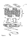
Figure 2 is an exploded view of the antenna array ofFigure 1 , showing a top down perspective of components thereof, and an optional off-axis conductive loading plate shown in relation to an antenna element thereof.Figure 3 is an exploded view of the antenna array ofFigure 1 , showing a bottom up perspective of components thereof. -
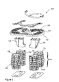
Figure 3 is an exploded view of the antenna array ofFigure 1 , showing a bottom up perspective of components thereof. -
Figure 4 is a perspective view of an antenna element of the antenna array ofFigure 1 . -
Figure 5 is a perspective view of a helical antenna array, in accordance with another embodiment of the invention. - Unless defined otherwise, all technical and scientific terms used herein have the same meaning as commonly understood by one of ordinary skill in the art to which this invention belongs.
- The following provides a description of a helical antenna array, and antenna elements thereof, in accordance with different embodiments of the invention. In general, the array will comprise a ground plane and an array of helical antenna elements, each one of which comprising a support structure and a conductor helically supported thereby defining respective element axes extending from said ground plane in a direction substantially perpendicular thereto. For example, different embodiments may comprise two, four or more helical antenna elements, which, depending on the embodiment and the application for which the array is intended, may be substantially identical elements, or structurally or operationally different elements.
- As will be appreciated by the person of skill in the art, different embodiments may be designed and used for different applications. For instance, and as introduced above, helical antenna arrays are commonly used for satellite communications, which may include but are not limited to ground and/or airborne satellite communications, such as described above in the context of aircraft communications. Clearly, while some of the embodiments described below may be particularly amenable for use in aircraft communication systems, these embodiments are not intended to be limited as such, as the features of these embodiments, and the operational improvements and/or advantages provided thereby, may be equally applicable in other contexts where helical antenna arrays are commonly used, as will be appreciated by the person of ordinary skill in the art. For the purpose of the following description, however, the embodiments of the invention will be described within the context of aircraft communications, and particularly, wherein an antenna array is generally mounted for operation within the limited spatial confines of a radome or the like, as commonly found at the tail end of an aircraft, and wherein operation of the antenna array requires a certain level of spatial freedom in allowing the array to sweep a suitable scan area to provide suitable coverage. Accordingly, in accordance with some embodiments, improvements in the performance of the antenna array are provided in comparison with traditional arrays having similar spatial dimensions or profiles, thereby providing a potential replacement for traditional arrays without imposing changes to existing spatial restrictions for such antennas.
- For instance, and in accordance with some embodiments of the invention, the antenna array may incorporate one or more of the below-described modifications, which, alone or in different combinations, may increase the overall gain in the array, reduce dissipative losses in the array, or improve the array's manufacturability,. In the context of a steerable antenna in aircraft communication systems, where a helix array may be subject to continuous reorientation by tilting the array and its beam so that it can be pointed in different directions, these modifications may, in accordance with different embodiments, allow for maintaining an overall sweeping volume of the antenna array while achieving higher gains. Further, the antenna structure can generally be rotated about each of two orthogonal axes in order to synthesize volumetric coverage. In some embodiments, each axis passes through the centre of the antenna structure, thereby reducing the scan envelope of the array, i.e. the single envelope that contains the antenna assembly in all its various different scan orientations; this scan envelope will thus fix the minimum size of the radome structure within which the antenna components can be housed. On an aircraft, there are generally many hard limitations relating to the available spaces within which the antenna can be installed; therefore, achieving significant operational gains without significantly increasing the overall antenna structure can provide significant advantages in this field. As indicated above, however, the operational gains achieved by the embodiments of the invention herein described are equally applicable in other contexts where structural size limitations are not as strictly applicable.
- It will be appreciated that the examples provided below describe, in accordance with different embodiments of the invention, different features, which, alone or in combination, can allow for an improved helical antenna array performance. Accordingly, the person of skill in the art will appreciate that while different features are combined in describing a same exemplary embodiment, these features may be equally considered alone or in different combinations to provide different desirable effects without departing from the general scope and nature of the present disclosure.
- Referring now to
Figures 1 to 4 , and in accordance with one exemplary embodiment of the invention, a helical antenna array, generally referred to using the numeral 100, will now be described. As shown in these Figures, thearray 100 generally comprises aground plane 102 and four substantiallyidentical antenna elements 104, each one of which extending substantially perpendicularly from the ground plane and comprising asupport structure 106 and a conductor 108 (e.g. conductive wire) helically supported thereby. It will be appreciated that while four antenna elements are depicted herein, different numbers of antenna elements may be considered herein without departing from the general scope and nature of the present disclosure. Namely the four-element examples depicted herein are meant as exemplary only, as the features described herein may be equally applicable to other arrays comprising two, three, four or more antenna elements. - Furthermore, and in accordance with one embodiment, each
support rib 116 may further comprise a series of notches orindentations 122 for receiving and thereby supporting theconductor 108. - In some embodiments, the provision of a rib-based former may provide for reduced mass and an improved RF performance due to a reduction in dielectric volume, and displacement of dielectric from the helix winding. The reduction in dielectric volume may further alleviate the otherwise perturbing propagations of electromagnetic fields around the winding. To enhance these positive effects, a series of apertures (i.e. windows) 124 may be provided within the
sleeve 114 between thesupport ribs 116 to further reduce the mass and dielectric volume of the antenna element, thereby reducing dielectric loading and losses induced by the provision of the former. - Referring now to
Figures 1 to 4 , theantenna array 100, in accordance with one embodiment of the invention, further comprises a number of additional features, which, alone or in combination, may allow for an improvement in array performance. - For example, the
ground plane 102 generally comprises aconductive sheet 130 or the like upon which theantenna elements 104 are mounted. As depicted inFigures 1 to 4 , theground sheet 130 extends laterally to define the base of the array, and terminates along its edges in a raisedlip 132. Theground plane 102 may be shaped to define anotch 134 through which a suitabledielectric spar 136 may be introduced for cooperative coupling to anarray mounting structure 138 provided on theground plane 102. The spar may allow for operative coupling of the array to a drive mechanism configured for rotating the array about an axis thereof. For example, the present embodiment allows for the array to rotate about a lateral axis located through a geometrical centerline of the array such that the rotation thereabout does not outwardly extend the sweeping envelope of the array. The present embodiment also allows for the array to longitudinally rotate about a perpendicular axis defined by a corresponding geometrical centerline of the array. The longitudinal rotation may be implemented through arotation platform 140 upon which thespar 136 is mounted. Accordingly, the combined mechanism allows for a reorientation of theantenna array 100 about orthogonal axes within a prescribed sweeping envelope substantially defined by the diameter of thebase plane 102 and the diameter of the array at the terminal end of thehelical antenna elements 104. For this purpose, the outer edge of the ground plane may be appropriately shaped to allow for the rotation of the four-helix array without mechanical interference with the scanning mechanism. - In another embodiment, one or more ground cups, rather than a single ground plane, may be used to provide, in some implementations, for greater efficiency and gain.
- In another embodiment, the
spar 136 is manufactured of a dielectric material incorporating one or more air pockets as a means for reducing the amount of dielectric material within the array volume and thus reducing the potential impact that the spar may have on array performance. - In another embodiment, the
base plane 102 may further comprise a series of apertures defined therein, such asapertures 142, wherein the dimension of these apertures allows one or more bands of electromagnetic field frequency to pass through theplane 102 with reduced attenuation comparing with a similar plane devoid of such apertures. - With reference to
Figures 1 to 4 , the helix windings, depicted herein as helically woundconductive wires 108, may further have electrically coupled thereto, respective conductive strips attached along a section of these wires as a means of increasing capacitive loading, thereby facilitating impedance matching. For example, in this embodiment, one or moreconductive strips 152 are provided toward the feeding ends of the helical windings. A person of ordinary skill in the art will nonetheless appreciate that further or alternative conductive members may be disposed about the helical windings to provide similar effects. - Still referring to
Figures 1 to 4 , the nominal helix axes may further be rotated relative to each other such that the space between their respective feed points is increased for reduced coupling and increased array gain. - Referring now to
Figure 5 and in accordance with another embodiment of the invention, an alternativehelical antenna array 500 will now be described, wherein like reference numerals are used to describe similar parts. In this embodiment, four linearhelical antenna elements 504 are provided, each one of which comprising a substantially linear former 506 about which a conductor, such as awire 508, is helically disposed. Like the embodiments ofFigures 1 to 4 , the former 506 comprises a nominallycylindrical sleeve 514 having a series of radially extendingribs 516 upon which the windingconductor 508 is mounted thereby defining a substantially piece-wise linear configuration. - It is apparent that the foregoing embodiments of the invention are exemplary and can be varied in many ways. Such present or future variations are not to be regarded as a departure from the scope of the invention, and all such modifications as would be obvious to one skilled in the art are intended to be included within the scope of the following claims.
Claims (8)
- An antenna comprising:a ground plane (102); andan array (100) of helical antenna elements (104), each helical antenna element (104) comprising a support structure (106) and a conductor (108) helically supported thereby defining respective element axes extending from the ground plane (102) in a direction substantially perpendicular thereto, the helical antenna element (104) having a terminal end and having a base end mounted to the ground plane (102);wherein the support structure (106) of at least one helical antenna element (104) comprises a series of support ribs (116) extending substantially radially outward from an internal, dielectric cylinder, the support ribs (116) comprising a series of substantially parallel longitudinal ribs symmetrically circumscribing the support structure (106); characterised in that the dielectric cylinder is hollow andwherein the conductor (108) of the at least one helical antenna element (104) is disposed about the support ribs (116) to define a substantially piece-wise linear conductive helix.
- The antenna of claim 1, wherein each support rib (116) comprises a plurality of notches (122) for receiving and thereby supporting the conductor (108) of the at least one helical antenna element (104).
- The antenna of claim 1, wherein the substantially piece-wise linear conductive helix defines a substantially polygonal element cross-section.
- The antenna of claim 1, wherein the support structure (106) of the at least one helical antenna element (104) has a plurality of ribs (116) for supporting the conductor (108) of the at least one helical antenna element (104), and has apertures (142) defined therein between said ribs (116).
- The antenna of any one of claims 1 to 4, wherein the conductor (108) of the at least one helical antenna element (104) comprises a conductive wire.
- The antenna of any one of claims 1 to 5, wherein one or more respective axes of the helical antenna elements (104) are rotated relative one to another thereby distancing respective feed points thereof and reducing the coupling between the helical antenna elements (104).
- The antenna of any one of claims 1 to 6, further comprising an antenna orientation mechanism for orienting the antenna about at least one axis of rotation, wherein a sweeping envelope of the antenna about the at least one axis is defined by at least one of a base plane dimension and a combined dimension of antenna element terminal ends.
- The antenna of claim 7, wherein the antenna orientation mechanism is further for orienting the antenna about two substantially orthogonal axes.
Applications Claiming Priority (2)
| Application Number | Priority Date | Filing Date | Title |
|---|---|---|---|
| US25235509P | 2009-10-16 | 2009-10-16 | |
| PCT/CA2010/000343 WO2011044656A1 (en) | 2009-10-16 | 2010-03-09 | Increased gain in an array antenna through optimal suspension of piece-wise linear conductors |
Publications (3)
| Publication Number | Publication Date |
|---|---|
| EP2489097A1 EP2489097A1 (en) | 2012-08-22 |
| EP2489097A4 EP2489097A4 (en) | 2013-03-27 |
| EP2489097B1 true EP2489097B1 (en) | 2014-06-04 |
Family
ID=43875739
Family Applications (3)
| Application Number | Title | Priority Date | Filing Date |
|---|---|---|---|
| EP10822925.3A Active EP2489098B1 (en) | 2009-10-16 | 2010-03-09 | Spherical perturbation of an array antenna |
| EP10822926.1A Active EP2489097B1 (en) | 2009-10-16 | 2010-03-09 | Increased gain in an array antenna through optimal suspension of piece-wise linear conductors |
| EP10822927.9A Active EP2489099B1 (en) | 2009-10-16 | 2010-03-09 | Optimal loading for increased gain in an array antenna |
Family Applications Before (1)
| Application Number | Title | Priority Date | Filing Date |
|---|---|---|---|
| EP10822925.3A Active EP2489098B1 (en) | 2009-10-16 | 2010-03-09 | Spherical perturbation of an array antenna |
Family Applications After (1)
| Application Number | Title | Priority Date | Filing Date |
|---|---|---|---|
| EP10822927.9A Active EP2489099B1 (en) | 2009-10-16 | 2010-03-09 | Optimal loading for increased gain in an array antenna |
Country Status (4)
| Country | Link |
|---|---|
| US (3) | US9118118B2 (en) |
| EP (3) | EP2489098B1 (en) |
| JP (3) | JP5676622B2 (en) |
| WO (3) | WO2011044657A1 (en) |
Families Citing this family (6)
| Publication number | Priority date | Publication date | Assignee | Title |
|---|---|---|---|---|
| US9118118B2 (en) | 2009-10-16 | 2015-08-25 | Ems Technologies Canada, Ltd. | Increased gain in an array antenna through optimal suspension of piece-wise linear conductors |
| EP2675013A1 (en) * | 2012-06-11 | 2013-12-18 | Microelectronics Technology Inc. | Outdoor unit system and holder for outdoor unit |
| USD744985S1 (en) * | 2013-02-08 | 2015-12-08 | Ubiquiti Networks, Inc. | Radio system |
| CN104502187B (en) * | 2014-12-31 | 2016-09-14 | 哈尔滨工业大学 | Spaceborne cylinder antenna reflecting face decouples load test pedestal with displacement |
| DE102015010917A1 (en) * | 2015-08-20 | 2017-02-23 | Diehl Metering Gmbh | Antenna device for receiving and / or transmitting radio signals |
| US11258181B2 (en) | 2019-12-20 | 2022-02-22 | Eagle Technology, Llc | Systems and methods for providing a high gain space deployable helix antenna |
Family Cites Families (38)
| Publication number | Priority date | Publication date | Assignee | Title |
|---|---|---|---|---|
| US2919442A (en) | 1955-12-09 | 1959-12-29 | American Electronics | Antenna |
| US3510877A (en) | 1967-09-07 | 1970-05-05 | Int Standard Electric Corp | Antenna positioning device for following moving bodies |
| CH499888A (en) | 1967-12-15 | 1970-11-30 | Onera (Off Nat Aerospatiale) | Helically wound single conductor antenna of reduced dimensions, and method for its manufacture |
| US3852756A (en) | 1974-02-15 | 1974-12-03 | Us Navy | Electrically small resonant antenna with capacitively coupled load |
| US4427984A (en) | 1981-07-29 | 1984-01-24 | General Electric Company | Phase-variable spiral antenna and steerable arrays thereof |
| JPS6074314U (en) * | 1983-10-28 | 1985-05-24 | 日本電気株式会社 | helical antenna |
| JPH0227610A (en) | 1988-07-18 | 1990-01-30 | Toyobo Co Ltd | Elastic conductive wire and its manufacture |
| JPH0332811U (en) * | 1989-08-02 | 1991-03-29 | ||
| JPH0372703A (en) * | 1989-08-11 | 1991-03-27 | Nakamura Seisakusho:Kk | End fire type antenna equipment |
| US5216436A (en) | 1991-05-31 | 1993-06-01 | Harris Corporation | Collapsible, low visibility, broadband tapered helix monopole antenna |
| SE468917B (en) * | 1991-08-16 | 1993-04-05 | Ericsson Ge Mobile Communicat | MINIATURE ANTENNA |
| JP3317521B2 (en) * | 1992-07-06 | 2002-08-26 | 原田工業株式会社 | Manufacturing method of helical antenna for satellite communication |
| JP3317522B2 (en) | 1992-07-06 | 2002-08-26 | 原田工業株式会社 | Helical antenna for satellite communication |
| US5345248A (en) | 1992-07-22 | 1994-09-06 | Space Systems/Loral, Inc. | Staggered helical array antenna |
| JPH0677722A (en) * | 1992-08-19 | 1994-03-18 | Mitsubishi Electric Corp | Antenna device |
| US5479182A (en) * | 1993-03-01 | 1995-12-26 | Her Majesty The Queen In Right Of Canada, As Represented By The Minister Of Communications | Short conical antenna |
| JPH07263946A (en) * | 1994-03-25 | 1995-10-13 | Mitsubishi Electric Corp | Antenna device |
| JP3417682B2 (en) * | 1994-09-01 | 2003-06-16 | 三菱電機株式会社 | Array structure of helical antenna |
| US5874927A (en) | 1996-10-21 | 1999-02-23 | Knowles; Patrick J. | Tilted element antenna having increased effective aperture and method therefor |
| JPH1188021A (en) * | 1997-09-05 | 1999-03-30 | Matsushita Electric Ind Co Ltd | Coil structure and manufacturing method thereof |
| US6181296B1 (en) * | 1998-10-29 | 2001-01-30 | Harris Corporation | Cast core fabrication of helically wound antenna |
| US6172655B1 (en) * | 1999-02-12 | 2001-01-09 | Lockheed Martin Corporation | Ultra-short helical antenna and array thereof |
| US7230572B2 (en) | 2001-02-15 | 2007-06-12 | Integral Technologies, Inc. | Low cost antenna devices comprising conductive loaded resin-based materials with conductive wrapping |
| JP2002359514A (en) | 2001-05-31 | 2002-12-13 | Anten Corp | Helical antenna |
| US6646614B2 (en) | 2001-11-07 | 2003-11-11 | Harris Corporation | Multi-frequency band antenna and related methods |
| US6664938B2 (en) * | 2002-03-01 | 2003-12-16 | Ems Technologies Canada, Ltd. | Pentagonal helical antenna array |
| JP2004120168A (en) * | 2002-09-25 | 2004-04-15 | Matsushita Electric Ind Co Ltd | Helical antenna |
| US6836258B2 (en) | 2002-11-22 | 2004-12-28 | Ems Technologies Canada, Ltd. | Complementary dual antenna system |
| US6819302B2 (en) | 2003-01-15 | 2004-11-16 | Lockheed Martin Corporation | Dual port helical-dipole antenna and array |
| JP4093077B2 (en) * | 2003-02-21 | 2008-05-28 | 三菱電機株式会社 | Helical antenna |
| US7038636B2 (en) * | 2003-06-18 | 2006-05-02 | Ems Technologies Cawada, Ltd. | Helical antenna |
| JP2005072873A (en) | 2003-08-22 | 2005-03-17 | Hitachi Kokusai Electric Inc | Planar antenna |
| JP4533619B2 (en) | 2003-11-26 | 2010-09-01 | 日本無線株式会社 | Helical antenna and its array antenna |
| JP4063833B2 (en) * | 2004-06-14 | 2008-03-19 | Necアクセステクニカ株式会社 | Antenna device and portable radio terminal |
| US7142171B1 (en) | 2005-04-14 | 2006-11-28 | Lockheed Martin Corporation | Helix radiating elements for high power applications |
| US7454203B2 (en) | 2005-09-29 | 2008-11-18 | Nextel Communications, Inc. | System and method for providing wireless services to aircraft passengers |
| FR2903234B1 (en) | 2006-06-28 | 2011-03-18 | Macdonald Dettwiller And Associates Corp | PARASITE ELEMENT FOR HELICOIDAL ANTENNA. |
| US9118118B2 (en) | 2009-10-16 | 2015-08-25 | Ems Technologies Canada, Ltd. | Increased gain in an array antenna through optimal suspension of piece-wise linear conductors |
-
2010
- 2010-03-09 US US13/501,203 patent/US9118118B2/en active Active
- 2010-03-09 WO PCT/CA2010/000344 patent/WO2011044657A1/en not_active Ceased
- 2010-03-09 US US13/501,194 patent/US9054425B2/en active Active
- 2010-03-09 EP EP10822925.3A patent/EP2489098B1/en active Active
- 2010-03-09 WO PCT/CA2010/000339 patent/WO2011044655A1/en not_active Ceased
- 2010-03-09 WO PCT/CA2010/000343 patent/WO2011044656A1/en not_active Ceased
- 2010-03-09 EP EP10822926.1A patent/EP2489097B1/en active Active
- 2010-03-09 JP JP2012533439A patent/JP5676622B2/en not_active Expired - Fee Related
- 2010-03-09 US US13/501,199 patent/US9362625B2/en active Active
- 2010-03-09 EP EP10822927.9A patent/EP2489099B1/en active Active
- 2010-03-09 JP JP2012533437A patent/JP5676621B2/en not_active Expired - Fee Related
- 2010-03-09 JP JP2012533438A patent/JP5756114B2/en not_active Expired - Fee Related
Also Published As
| Publication number | Publication date |
|---|---|
| EP2489098A4 (en) | 2013-03-27 |
| US20120280875A1 (en) | 2012-11-08 |
| JP2013507849A (en) | 2013-03-04 |
| EP2489097A1 (en) | 2012-08-22 |
| EP2489097A4 (en) | 2013-03-27 |
| EP2489099A4 (en) | 2013-03-27 |
| WO2011044655A1 (en) | 2011-04-21 |
| JP5676622B2 (en) | 2015-02-25 |
| JP2013507851A (en) | 2013-03-04 |
| EP2489099A1 (en) | 2012-08-22 |
| US20120256797A1 (en) | 2012-10-11 |
| WO2011044655A9 (en) | 2011-06-03 |
| EP2489098B1 (en) | 2015-04-15 |
| US9054425B2 (en) | 2015-06-09 |
| JP2013507850A (en) | 2013-03-04 |
| US9118118B2 (en) | 2015-08-25 |
| JP5756114B2 (en) | 2015-07-29 |
| EP2489098A1 (en) | 2012-08-22 |
| WO2011044657A1 (en) | 2011-04-21 |
| US20120268334A1 (en) | 2012-10-25 |
| JP5676621B2 (en) | 2015-02-25 |
| US9362625B2 (en) | 2016-06-07 |
| WO2011044657A9 (en) | 2011-06-16 |
| WO2011044656A1 (en) | 2011-04-21 |
| EP2489099B1 (en) | 2013-10-23 |
| WO2011044656A9 (en) | 2011-06-23 |
Similar Documents
| Publication | Publication Date | Title |
|---|---|---|
| RU2222077C2 (en) | Multiple-segment spiral antenna with coupled segments | |
| US9444148B2 (en) | Printed quasi-tapered tape helical array antenna | |
| US6828948B2 (en) | Broadband starfish antenna and array thereof | |
| US3906509A (en) | Circularly polarized helix and spiral antennas | |
| JP3189735B2 (en) | Helical antenna | |
| US6664938B2 (en) | Pentagonal helical antenna array | |
| US9653801B2 (en) | Selectable low-gain/high-gain beam implementation for VICTS antenna arrays | |
| US6344834B1 (en) | Low angle, high angle quadrifilar helix antenna | |
| US9118118B2 (en) | Increased gain in an array antenna through optimal suspension of piece-wise linear conductors | |
| US11502414B2 (en) | Microstrip patch antenna system having adjustable radiation pattern shapes and related method | |
| EP1514329B1 (en) | Helix antenna | |
| US10965012B2 (en) | Multi-filar helical antenna | |
| US11682841B2 (en) | Communications device with helically wound conductive strip and related antenna devices and methods | |
| US6121936A (en) | Conformable, integrated antenna structure providing multiple radiating apertures | |
| US10931019B1 (en) | Helix antenna | |
| US20240136727A1 (en) | Communications device with helical slot radiating antenna and related antenna device and method | |
| KR100886511B1 (en) | QH feeder using Wilkinson power divider with 90 degree phase difference | |
| CN121355593B (en) | Dual-frequency high-gain narrow-beam antenna, terminal and unmanned equipment | |
| JP2008205647A (en) | Antenna | |
| ZA200410098B (en) | Helix antenna |
Legal Events
| Date | Code | Title | Description |
|---|---|---|---|
| PUAI | Public reference made under article 153(3) epc to a published international application that has entered the european phase |
Free format text: ORIGINAL CODE: 0009012 |
|
| 17P | Request for examination filed |
Effective date: 20120405 |
|
| AK | Designated contracting states |
Kind code of ref document: A1 Designated state(s): AT BE BG CH CY CZ DE DK EE ES FI FR GB GR HR HU IE IS IT LI LT LU LV MC MK MT NL NO PL PT RO SE SI SK SM TR |
|
| DAX | Request for extension of the european patent (deleted) | ||
| A4 | Supplementary search report drawn up and despatched |
Effective date: 20130226 |
|
| RIC1 | Information provided on ipc code assigned before grant |
Ipc: H01Q 21/06 20060101ALI20130220BHEP Ipc: H01Q 11/08 20060101AFI20130220BHEP Ipc: H01Q 1/36 20060101ALI20130220BHEP |
|
| 17Q | First examination report despatched |
Effective date: 20130308 |
|
| 17Q | First examination report despatched |
Effective date: 20130906 |
|
| REG | Reference to a national code |
Ref country code: DE Ref legal event code: R079 Ref document number: 602010016549 Country of ref document: DE Free format text: PREVIOUS MAIN CLASS: H01Q0001160000 Ipc: H01Q0011080000 |
|
| GRAP | Despatch of communication of intention to grant a patent |
Free format text: ORIGINAL CODE: EPIDOSNIGR1 |
|
| RIC1 | Information provided on ipc code assigned before grant |
Ipc: H01Q 1/36 20060101ALI20140128BHEP Ipc: H01Q 11/08 20060101AFI20140128BHEP Ipc: H01Q 21/06 20060101ALI20140128BHEP |
|
| INTG | Intention to grant announced |
Effective date: 20140226 |
|
| GRAS | Grant fee paid |
Free format text: ORIGINAL CODE: EPIDOSNIGR3 |
|
| GRAA | (expected) grant |
Free format text: ORIGINAL CODE: 0009210 |
|
| AK | Designated contracting states |
Kind code of ref document: B1 Designated state(s): AT BE BG CH CY CZ DE DK EE ES FI FR GB GR HR HU IE IS IT LI LT LU LV MC MK MT NL NO PL PT RO SE SI SK SM TR |
|
| REG | Reference to a national code |
Ref country code: GB Ref legal event code: FG4D |
|
| REG | Reference to a national code |
Ref country code: CH Ref legal event code: EP |
|
| REG | Reference to a national code |
Ref country code: AT Ref legal event code: REF Ref document number: 671552 Country of ref document: AT Kind code of ref document: T Effective date: 20140615 |
|
| REG | Reference to a national code |
Ref country code: IE Ref legal event code: FG4D |
|
| REG | Reference to a national code |
Ref country code: DE Ref legal event code: R096 Ref document number: 602010016549 Country of ref document: DE Effective date: 20140717 |
|
| REG | Reference to a national code |
Ref country code: AT Ref legal event code: MK05 Ref document number: 671552 Country of ref document: AT Kind code of ref document: T Effective date: 20140604 |
|
| REG | Reference to a national code |
Ref country code: NL Ref legal event code: VDEP Effective date: 20140604 |
|
| PG25 | Lapsed in a contracting state [announced via postgrant information from national office to epo] |
Ref country code: GR Free format text: LAPSE BECAUSE OF FAILURE TO SUBMIT A TRANSLATION OF THE DESCRIPTION OR TO PAY THE FEE WITHIN THE PRESCRIBED TIME-LIMIT Effective date: 20140905 Ref country code: NO Free format text: LAPSE BECAUSE OF FAILURE TO SUBMIT A TRANSLATION OF THE DESCRIPTION OR TO PAY THE FEE WITHIN THE PRESCRIBED TIME-LIMIT Effective date: 20140904 Ref country code: LT Free format text: LAPSE BECAUSE OF FAILURE TO SUBMIT A TRANSLATION OF THE DESCRIPTION OR TO PAY THE FEE WITHIN THE PRESCRIBED TIME-LIMIT Effective date: 20140604 Ref country code: FI Free format text: LAPSE BECAUSE OF FAILURE TO SUBMIT A TRANSLATION OF THE DESCRIPTION OR TO PAY THE FEE WITHIN THE PRESCRIBED TIME-LIMIT Effective date: 20140604 Ref country code: CY Free format text: LAPSE BECAUSE OF FAILURE TO SUBMIT A TRANSLATION OF THE DESCRIPTION OR TO PAY THE FEE WITHIN THE PRESCRIBED TIME-LIMIT Effective date: 20140604 |
|
| REG | Reference to a national code |
Ref country code: LT Ref legal event code: MG4D |
|
| PG25 | Lapsed in a contracting state [announced via postgrant information from national office to epo] |
Ref country code: AT Free format text: LAPSE BECAUSE OF FAILURE TO SUBMIT A TRANSLATION OF THE DESCRIPTION OR TO PAY THE FEE WITHIN THE PRESCRIBED TIME-LIMIT Effective date: 20140604 Ref country code: SE Free format text: LAPSE BECAUSE OF FAILURE TO SUBMIT A TRANSLATION OF THE DESCRIPTION OR TO PAY THE FEE WITHIN THE PRESCRIBED TIME-LIMIT Effective date: 20140604 Ref country code: HR Free format text: LAPSE BECAUSE OF FAILURE TO SUBMIT A TRANSLATION OF THE DESCRIPTION OR TO PAY THE FEE WITHIN THE PRESCRIBED TIME-LIMIT Effective date: 20140604 Ref country code: LV Free format text: LAPSE BECAUSE OF FAILURE TO SUBMIT A TRANSLATION OF THE DESCRIPTION OR TO PAY THE FEE WITHIN THE PRESCRIBED TIME-LIMIT Effective date: 20140604 |
|
| PG25 | Lapsed in a contracting state [announced via postgrant information from national office to epo] |
Ref country code: RO Free format text: LAPSE BECAUSE OF FAILURE TO SUBMIT A TRANSLATION OF THE DESCRIPTION OR TO PAY THE FEE WITHIN THE PRESCRIBED TIME-LIMIT Effective date: 20140604 Ref country code: EE Free format text: LAPSE BECAUSE OF FAILURE TO SUBMIT A TRANSLATION OF THE DESCRIPTION OR TO PAY THE FEE WITHIN THE PRESCRIBED TIME-LIMIT Effective date: 20140604 Ref country code: PT Free format text: LAPSE BECAUSE OF FAILURE TO SUBMIT A TRANSLATION OF THE DESCRIPTION OR TO PAY THE FEE WITHIN THE PRESCRIBED TIME-LIMIT Effective date: 20141006 Ref country code: SK Free format text: LAPSE BECAUSE OF FAILURE TO SUBMIT A TRANSLATION OF THE DESCRIPTION OR TO PAY THE FEE WITHIN THE PRESCRIBED TIME-LIMIT Effective date: 20140604 Ref country code: CZ Free format text: LAPSE BECAUSE OF FAILURE TO SUBMIT A TRANSLATION OF THE DESCRIPTION OR TO PAY THE FEE WITHIN THE PRESCRIBED TIME-LIMIT Effective date: 20140604 Ref country code: ES Free format text: LAPSE BECAUSE OF FAILURE TO SUBMIT A TRANSLATION OF THE DESCRIPTION OR TO PAY THE FEE WITHIN THE PRESCRIBED TIME-LIMIT Effective date: 20140604 |
|
| PG25 | Lapsed in a contracting state [announced via postgrant information from national office to epo] |
Ref country code: NL Free format text: LAPSE BECAUSE OF FAILURE TO SUBMIT A TRANSLATION OF THE DESCRIPTION OR TO PAY THE FEE WITHIN THE PRESCRIBED TIME-LIMIT Effective date: 20140604 Ref country code: PL Free format text: LAPSE BECAUSE OF FAILURE TO SUBMIT A TRANSLATION OF THE DESCRIPTION OR TO PAY THE FEE WITHIN THE PRESCRIBED TIME-LIMIT Effective date: 20140604 Ref country code: IS Free format text: LAPSE BECAUSE OF FAILURE TO SUBMIT A TRANSLATION OF THE DESCRIPTION OR TO PAY THE FEE WITHIN THE PRESCRIBED TIME-LIMIT Effective date: 20141004 |
|
| REG | Reference to a national code |
Ref country code: DE Ref legal event code: R097 Ref document number: 602010016549 Country of ref document: DE |
|
| PLBE | No opposition filed within time limit |
Free format text: ORIGINAL CODE: 0009261 |
|
| STAA | Information on the status of an ep patent application or granted ep patent |
Free format text: STATUS: NO OPPOSITION FILED WITHIN TIME LIMIT |
|
| PG25 | Lapsed in a contracting state [announced via postgrant information from national office to epo] |
Ref country code: DK Free format text: LAPSE BECAUSE OF FAILURE TO SUBMIT A TRANSLATION OF THE DESCRIPTION OR TO PAY THE FEE WITHIN THE PRESCRIBED TIME-LIMIT Effective date: 20140604 Ref country code: IT Free format text: LAPSE BECAUSE OF FAILURE TO SUBMIT A TRANSLATION OF THE DESCRIPTION OR TO PAY THE FEE WITHIN THE PRESCRIBED TIME-LIMIT Effective date: 20140604 |
|
| 26N | No opposition filed |
Effective date: 20150305 |
|
| REG | Reference to a national code |
Ref country code: DE Ref legal event code: R097 Ref document number: 602010016549 Country of ref document: DE Effective date: 20150305 |
|
| PG25 | Lapsed in a contracting state [announced via postgrant information from national office to epo] |
Ref country code: BE Free format text: LAPSE BECAUSE OF FAILURE TO SUBMIT A TRANSLATION OF THE DESCRIPTION OR TO PAY THE FEE WITHIN THE PRESCRIBED TIME-LIMIT Effective date: 20140604 |
|
| PG25 | Lapsed in a contracting state [announced via postgrant information from national office to epo] |
Ref country code: SI Free format text: LAPSE BECAUSE OF FAILURE TO SUBMIT A TRANSLATION OF THE DESCRIPTION OR TO PAY THE FEE WITHIN THE PRESCRIBED TIME-LIMIT Effective date: 20140604 |
|
| PG25 | Lapsed in a contracting state [announced via postgrant information from national office to epo] |
Ref country code: MC Free format text: LAPSE BECAUSE OF FAILURE TO SUBMIT A TRANSLATION OF THE DESCRIPTION OR TO PAY THE FEE WITHIN THE PRESCRIBED TIME-LIMIT Effective date: 20140604 Ref country code: LU Free format text: LAPSE BECAUSE OF FAILURE TO SUBMIT A TRANSLATION OF THE DESCRIPTION OR TO PAY THE FEE WITHIN THE PRESCRIBED TIME-LIMIT Effective date: 20150309 |
|
| REG | Reference to a national code |
Ref country code: CH Ref legal event code: PL |
|
| REG | Reference to a national code |
Ref country code: IE Ref legal event code: MM4A |
|
| PG25 | Lapsed in a contracting state [announced via postgrant information from national office to epo] |
Ref country code: LI Free format text: LAPSE BECAUSE OF NON-PAYMENT OF DUE FEES Effective date: 20150331 Ref country code: CH Free format text: LAPSE BECAUSE OF NON-PAYMENT OF DUE FEES Effective date: 20150331 Ref country code: IE Free format text: LAPSE BECAUSE OF NON-PAYMENT OF DUE FEES Effective date: 20150309 |
|
| REG | Reference to a national code |
Ref country code: FR Ref legal event code: PLFP Year of fee payment: 7 |
|
| PG25 | Lapsed in a contracting state [announced via postgrant information from national office to epo] |
Ref country code: MT Free format text: LAPSE BECAUSE OF FAILURE TO SUBMIT A TRANSLATION OF THE DESCRIPTION OR TO PAY THE FEE WITHIN THE PRESCRIBED TIME-LIMIT Effective date: 20140604 |
|
| REG | Reference to a national code |
Ref country code: FR Ref legal event code: PLFP Year of fee payment: 8 |
|
| PG25 | Lapsed in a contracting state [announced via postgrant information from national office to epo] |
Ref country code: SM Free format text: LAPSE BECAUSE OF FAILURE TO SUBMIT A TRANSLATION OF THE DESCRIPTION OR TO PAY THE FEE WITHIN THE PRESCRIBED TIME-LIMIT Effective date: 20140604 Ref country code: HU Free format text: LAPSE BECAUSE OF FAILURE TO SUBMIT A TRANSLATION OF THE DESCRIPTION OR TO PAY THE FEE WITHIN THE PRESCRIBED TIME-LIMIT; INVALID AB INITIO Effective date: 20100309 Ref country code: BG Free format text: LAPSE BECAUSE OF FAILURE TO SUBMIT A TRANSLATION OF THE DESCRIPTION OR TO PAY THE FEE WITHIN THE PRESCRIBED TIME-LIMIT Effective date: 20140604 |
|
| PG25 | Lapsed in a contracting state [announced via postgrant information from national office to epo] |
Ref country code: TR Free format text: LAPSE BECAUSE OF FAILURE TO SUBMIT A TRANSLATION OF THE DESCRIPTION OR TO PAY THE FEE WITHIN THE PRESCRIBED TIME-LIMIT Effective date: 20140604 |
|
| REG | Reference to a national code |
Ref country code: FR Ref legal event code: PLFP Year of fee payment: 9 |
|
| PG25 | Lapsed in a contracting state [announced via postgrant information from national office to epo] |
Ref country code: MK Free format text: LAPSE BECAUSE OF FAILURE TO SUBMIT A TRANSLATION OF THE DESCRIPTION OR TO PAY THE FEE WITHIN THE PRESCRIBED TIME-LIMIT Effective date: 20140604 |
|
| PGFP | Annual fee paid to national office [announced via postgrant information from national office to epo] |
Ref country code: GB Payment date: 20220323 Year of fee payment: 13 |
|
| PGFP | Annual fee paid to national office [announced via postgrant information from national office to epo] |
Ref country code: FR Payment date: 20220325 Year of fee payment: 13 |
|
| P01 | Opt-out of the competence of the unified patent court (upc) registered |
Effective date: 20230830 |
|
| GBPC | Gb: european patent ceased through non-payment of renewal fee |
Effective date: 20230309 |
|
| PG25 | Lapsed in a contracting state [announced via postgrant information from national office to epo] |
Ref country code: GB Free format text: LAPSE BECAUSE OF NON-PAYMENT OF DUE FEES Effective date: 20230309 |
|
| PG25 | Lapsed in a contracting state [announced via postgrant information from national office to epo] |
Ref country code: GB Free format text: LAPSE BECAUSE OF NON-PAYMENT OF DUE FEES Effective date: 20230309 Ref country code: FR Free format text: LAPSE BECAUSE OF NON-PAYMENT OF DUE FEES Effective date: 20230331 |
|
| PGFP | Annual fee paid to national office [announced via postgrant information from national office to epo] |
Ref country code: DE Payment date: 20260320 Year of fee payment: 17 |