EP2487968B1 - Signalling of power information for mimo transmission in a wireless communication system - Google Patents
Signalling of power information for mimo transmission in a wireless communication system Download PDFInfo
- Publication number
- EP2487968B1 EP2487968B1 EP12167542.5A EP12167542A EP2487968B1 EP 2487968 B1 EP2487968 B1 EP 2487968B1 EP 12167542 A EP12167542 A EP 12167542A EP 2487968 B1 EP2487968 B1 EP 2487968B1
- Authority
- EP
- European Patent Office
- Prior art keywords
- power
- cqi
- node
- channelization codes
- transport block
- Prior art date
- Legal status (The legal status is an assumption and is not a legal conclusion. Google has not performed a legal analysis and makes no representation as to the accuracy of the status listed.)
- Active
Links
- 238000004891 communication Methods 0.000 title claims description 23
- 230000011664 signaling Effects 0.000 title description 21
- 230000005540 biological transmission Effects 0.000 title description 20
- 238000000034 method Methods 0.000 claims description 42
- 108010003272 Hyaluronate lyase Proteins 0.000 claims description 4
- 230000032258 transport Effects 0.000 description 150
- 238000013461 design Methods 0.000 description 39
- 230000008569 process Effects 0.000 description 18
- 239000013598 vector Substances 0.000 description 14
- 239000011159 matrix material Substances 0.000 description 12
- 238000012545 processing Methods 0.000 description 12
- 230000015654 memory Effects 0.000 description 10
- 230000006870 function Effects 0.000 description 7
- 238000005516 engineering process Methods 0.000 description 5
- 230000009046 primary transport Effects 0.000 description 5
- 230000009049 secondary transport Effects 0.000 description 5
- 230000001419 dependent effect Effects 0.000 description 4
- 238000010586 diagram Methods 0.000 description 4
- 238000013507 mapping Methods 0.000 description 4
- 230000007246 mechanism Effects 0.000 description 4
- 230000008859 change Effects 0.000 description 3
- 238000005259 measurement Methods 0.000 description 3
- 230000003287 optical effect Effects 0.000 description 3
- 238000004590 computer program Methods 0.000 description 2
- 230000001143 conditioned effect Effects 0.000 description 2
- 239000000835 fiber Substances 0.000 description 2
- 230000006872 improvement Effects 0.000 description 2
- 238000012886 linear function Methods 0.000 description 2
- 230000008520 organization Effects 0.000 description 2
- 239000002245 particle Substances 0.000 description 2
- 238000013341 scale-up Methods 0.000 description 2
- 241000760358 Enodes Species 0.000 description 1
- 239000000654 additive Substances 0.000 description 1
- 230000000996 additive effect Effects 0.000 description 1
- 230000001413 cellular effect Effects 0.000 description 1
- 230000000295 complement effect Effects 0.000 description 1
- 239000002131 composite material Substances 0.000 description 1
- 238000012986 modification Methods 0.000 description 1
- 230000004048 modification Effects 0.000 description 1
- 230000004044 response Effects 0.000 description 1
- 238000012546 transfer Methods 0.000 description 1
Images


Classifications
-
- H—ELECTRICITY
- H04—ELECTRIC COMMUNICATION TECHNIQUE
- H04B—TRANSMISSION
- H04B7/00—Radio transmission systems, i.e. using radiation field
- H04B7/02—Diversity systems; Multi-antenna system, i.e. transmission or reception using multiple antennas
- H04B7/04—Diversity systems; Multi-antenna system, i.e. transmission or reception using multiple antennas using two or more spaced independent antennas
- H04B7/0413—MIMO systems
- H04B7/0426—Power distribution
-
- H—ELECTRICITY
- H04—ELECTRIC COMMUNICATION TECHNIQUE
- H04B—TRANSMISSION
- H04B1/00—Details of transmission systems, not covered by a single one of groups H04B3/00 - H04B13/00; Details of transmission systems not characterised by the medium used for transmission
- H04B1/69—Spread spectrum techniques
- H04B1/707—Spread spectrum techniques using direct sequence modulation
-
- H—ELECTRICITY
- H04—ELECTRIC COMMUNICATION TECHNIQUE
- H04B—TRANSMISSION
- H04B17/00—Monitoring; Testing
- H04B17/20—Monitoring; Testing of receivers
- H04B17/24—Monitoring; Testing of receivers with feedback of measurements to the transmitter
-
- H—ELECTRICITY
- H04—ELECTRIC COMMUNICATION TECHNIQUE
- H04B—TRANSMISSION
- H04B7/00—Radio transmission systems, i.e. using radiation field
- H04B7/02—Diversity systems; Multi-antenna system, i.e. transmission or reception using multiple antennas
- H04B7/04—Diversity systems; Multi-antenna system, i.e. transmission or reception using multiple antennas using two or more spaced independent antennas
- H04B7/06—Diversity systems; Multi-antenna system, i.e. transmission or reception using multiple antennas using two or more spaced independent antennas at the transmitting station
- H04B7/0613—Diversity systems; Multi-antenna system, i.e. transmission or reception using multiple antennas using two or more spaced independent antennas at the transmitting station using simultaneous transmission
- H04B7/0615—Diversity systems; Multi-antenna system, i.e. transmission or reception using multiple antennas using two or more spaced independent antennas at the transmitting station using simultaneous transmission of weighted versions of same signal
- H04B7/0619—Diversity systems; Multi-antenna system, i.e. transmission or reception using multiple antennas using two or more spaced independent antennas at the transmitting station using simultaneous transmission of weighted versions of same signal using feedback from receiving side
- H04B7/0621—Feedback content
- H04B7/0632—Channel quality parameters, e.g. channel quality indicator [CQI]
-
- H—ELECTRICITY
- H04—ELECTRIC COMMUNICATION TECHNIQUE
- H04J—MULTIPLEX COMMUNICATION
- H04J13/00—Code division multiplex systems
- H04J13/0007—Code type
- H04J13/004—Orthogonal
- H04J13/0044—OVSF [orthogonal variable spreading factor]
-
- H—ELECTRICITY
- H04—ELECTRIC COMMUNICATION TECHNIQUE
- H04L—TRANSMISSION OF DIGITAL INFORMATION, e.g. TELEGRAPHIC COMMUNICATION
- H04L1/00—Arrangements for detecting or preventing errors in the information received
- H04L1/0001—Systems modifying transmission characteristics according to link quality, e.g. power backoff
- H04L1/0033—Systems modifying transmission characteristics according to link quality, e.g. power backoff arrangements specific to the transmitter
- H04L1/0034—Systems modifying transmission characteristics according to link quality, e.g. power backoff arrangements specific to the transmitter where the transmitter decides based on inferences, e.g. use of implicit signalling
-
- H—ELECTRICITY
- H04—ELECTRIC COMMUNICATION TECHNIQUE
- H04W—WIRELESS COMMUNICATION NETWORKS
- H04W52/00—Power management, e.g. TPC [Transmission Power Control], power saving or power classes
- H04W52/04—TPC
- H04W52/30—TPC using constraints in the total amount of available transmission power
- H04W52/32—TPC of broadcast or control channels
- H04W52/325—Power control of control or pilot channels
-
- H—ELECTRICITY
- H04—ELECTRIC COMMUNICATION TECHNIQUE
- H04W—WIRELESS COMMUNICATION NETWORKS
- H04W52/00—Power management, e.g. TPC [Transmission Power Control], power saving or power classes
- H04W52/04—TPC
- H04W52/30—TPC using constraints in the total amount of available transmission power
- H04W52/34—TPC management, i.e. sharing limited amount of power among users or channels or data types, e.g. cell loading
- H04W52/346—TPC management, i.e. sharing limited amount of power among users or channels or data types, e.g. cell loading distributing total power among users or channels
-
- H—ELECTRICITY
- H04—ELECTRIC COMMUNICATION TECHNIQUE
- H04W—WIRELESS COMMUNICATION NETWORKS
- H04W72/00—Local resource management
- H04W72/50—Allocation or scheduling criteria for wireless resources
- H04W72/54—Allocation or scheduling criteria for wireless resources based on quality criteria
- H04W72/542—Allocation or scheduling criteria for wireless resources based on quality criteria using measured or perceived quality
-
- H—ELECTRICITY
- H04—ELECTRIC COMMUNICATION TECHNIQUE
- H04W—WIRELESS COMMUNICATION NETWORKS
- H04W76/00—Connection management
- H04W76/20—Manipulation of established connections
- H04W76/27—Transitions between radio resource control [RRC] states
-
- H—ELECTRICITY
- H04—ELECTRIC COMMUNICATION TECHNIQUE
- H04W—WIRELESS COMMUNICATION NETWORKS
- H04W88/00—Devices specially adapted for wireless communication networks, e.g. terminals, base stations or access point devices
- H04W88/02—Terminal devices
-
- H—ELECTRICITY
- H04—ELECTRIC COMMUNICATION TECHNIQUE
- H04W—WIRELESS COMMUNICATION NETWORKS
- H04W88/00—Devices specially adapted for wireless communication networks, e.g. terminals, base stations or access point devices
- H04W88/08—Access point devices
Definitions
- the present disclosure relates generally to communication, and more specifically to techniques for signaling power information in a wireless communication system.
- a Node B may utilize multiple (T) transmit antennas for data transmission to a user equipment (UE) equipped with multiple (R) receive antennas.
- the multiple transmit and receive antennas form a multiple-input multiple-output (MIMO) channel that may be used to increase throughput and/or improve reliability.
- MIMO multiple-input multiple-output
- the Node B may transmit up to T data streams simultaneously from the T transmit antennas to improve throughput.
- the Node B may transmit a single data stream from all T transmit antennas to improve reception quality by the UE.
- Each data stream may carry one transport block of data in a given transmission time interval (TTI).
- TTI transmission time interval
- Good performance may be achieved by sending each transport block at the highest possible rate that still allows the UE to reliably decode the transport block.
- the UE may estimate signal-to-interference-and-noise ratios (SINRs) of each possible precoding combination of transport blocks that might be transmitted and may then determine channel quality indicator (CQI) information based on the estimated SINRs of the best precoding combination of transport blocks.
- SINRs signal-to-interference-and-noise ratios
- CQI channel quality indicator
- the CQI information may convey a set of processing parameters for each transport block.
- the UE may send the CQI information to the Node B.
- the Node B may process one or more transport blocks in accordance with the CQI information and send the transport block(s) to the UE.
- CQI Reporting for FDD MIMO R1-070513, 3GPP, 10 January 2007 , discusses a scheme for defining CQI vales of type A CQI reports in support of FDD MIMO.
- Definition of MIMO operation on HS-PDSCH, preferred precoding and CQI reporting procedures, modified CQI tables R1-070514, 3GPP, 10 January 2007 , relates to definition of details on the D-TxAA transmit processing and the procedure to produce composite PCI/CQI reports in caser the UE is configured in MIMO mode.
- the present invention relates to methods and apparatuses for wireless communication as defined in the appended claims.
- the SINR of a transport block may be dependent on power per channelization code, P OVSF , but may not be a linear function of P OVSF .
- a Node B may send power information that may be used by a UE to determine P OVSF , which may then be used for SINR estimation.
- the power information comprises a power offset between the power of a data channel, P HSPDSCH , and the power of a pilot channel, P CPICH .
- the data channel may comprise any number of channelization codes.
- P HSPDSCH may be given for a designated number of channelization codes, M, which may be a known value or provided via signaling.
- the Node B may determine P HSPDSCH based on the power available for the data channel, P ⁇ HSPDSCH , the number of channelization codes available for the data channel, K, and the designated number of channelization codes, M.
- P HSPDSCH may be greater than P ⁇ HSPDSCH if the designated number of channelization codes is greater than the number of available channelization codes.
- the UE may receive the power information from the Node B and may determine P OVSF based on the power information and the designated number of channelization codes.
- the UE may obtain the power offset from the power information and compute P HSPDSCH based on the power offset and the known P CPICH .
- the UE may then distribute P HSPDSCH across at least one transport block and also across the designated number of channelization codes to obtain P OVSF .
- the UE may estimate the SINR of each transport block based on P OVSF and then determine CQI information for the at least one transport block based on the SINR of each transport block.
- the UE may send the CQI information to the Node B.
- the Node B may receive the CQI information from the UE and may send at least one transport block in a MIMO transmission to the UE.
- the Node B may send the transport block(s) with the designated number of channelization codes and at P OVSF or higher.
- the Node B may send the transport block(s) with K available channelization codes at P OVSF or higher and may scale the size of the transport block(s) based on the designated number of channelization codes, M, and the number of available channelization codes, K.
- the Node B may scale P OVSF based on K and M and may then send the transport block(s) with the K available channelization codes at the scaled P OVSF .
- CDMA Code Division Multiple Access
- TDMA Time Division Multiple Access
- FDMA Frequency Division Multiple Access
- OFDMA Orthogonal FDMA
- SC-FDMA Single-Carrier FDMA
- a CDMA system may implement a radio technology such Universal Terrestrial Radio Access (UTRA), cdma2000, etc.
- UTRA includes Wideband-CDMA (W-CDMA) and other CDMA variants.
- cdma2000 covers IS-2000, IS-95 and IS-856 standards.
- UTRA is part of Universal Mobile Telecommunication System (UMTS), and both are described in documents from an organization named “3rd Generation Partnership Project” (3GPP).
- 3GPP 3rd Generation Partnership Project
- cdma2000 is described in documents from an organization named “3rd Generation Partnership Project 2” (3GPP2).
- 3GPP2 3rd Generation Partnership Project 2
- FIG. 1 shows a wireless communication system 100 with multiple Node Bs 110 and multiple UEs 120.
- System 100 may also be referred to as a Universal Terrestrial Radio Access Network (UTRAN) in UMTS.
- a Node B is generally a fixed station that communicates with the UEs and may also be referred to as an evolved Node B (eNode B), a base station, an access point, etc.
- eNode B evolved Node B
- Each Node B 110 provides communication coverage for a particular geographic area and supports communication for the UEs located within the coverage area.
- a system controller 130 couples to Node Bs 110 and provides coordination and control for these Node Bs.
- System controller 130 may be a single network entity or a collection of network entities.
- UEs 120 may be dispersed throughout the system, and each UE may be stationary or mobile.
- a UE may also be referred to as a mobile station, a terminal, an access terminal, a subscriber unit, a station, etc.
- a UE may be a cellular phone, a personal digital assistant (PDA), a wireless device, a handheld device, a wireless modem, a laptop computer, etc.
- PDA personal digital assistant
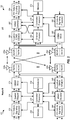
- FIG. 2 shows a block diagram of a design of one Node B 110 and one UE 120.
- Node B 110 is equipped with multiple (T) antennas 220a through 220t
- UE 120 is equipped with multiple (R) antennas 252a through 252r.
- a MIMO transmission may be sent from the T transmit antennas at Node B 110 to the R receive antennas at UE 120.
- a transmit (TX) data and signaling processor 212 may receive data from a data source (not shown) for all scheduled UEs.
- Processor 212 may process (e.g., format, encode, interleave, and symbol map) the data for each UE and provide data symbols, which are modulation symbols for data.
- Processor 212 may also process signaling (e.g., power information) and provides signaling symbols, which are modulation symbols for signaling.
- a spatial mapper 214 may precode the data symbols for each UE based on a precoding matrix or vector for that UE and provide output symbols for all UEs.
- a CDMA modulator (MOD) 216 may perform CDMA processing on the output symbols and signaling symbols and may provide T output chip streams to T transmitters (TMTR) 218a through 218t.
- Each transmitter 218 may process (e.g., convert to analog, filter, amplify, and frequency upconvert) its output chip stream and provide a downlink signal.
- T downlink signals from T transmitters 218a through 218t may be sent via T antennas 220a through 220t, respectively.
- R antennas 252a through 252r may receive the downlink signals from Node B 110 and provide R received signals to R receivers (RCVR) 254a through 254r, respectively.
- Each receiver 254 may process (e.g., filter, amplify, frequency downconvert, and digitize) its received signal and provide samples to a channel processor 268 and an equalizer/CDMA demodulator (DEMOD) 260.
- Processor 268 may derive coefficients for a front-end filter/equalizer and coefficients for one or more combiner matrices for equalizer/CDMA demodulator 260.
- Unit 260 may perform equalization with the front-end filter and CDMA demodulation and may provide filtered symbols.
- a MIMO detector 262 may combine the filtered symbols across spatial dimension and provide detected symbols, which are estimates of the data symbols and signaling symbols sent to UE 120.
- a receive (RX) data and signaling processor 264 may process (e.g., symbol demap, deinterleave, and decode) the detected symbols and provide decoded data and signaling.
- RX data and signaling processor 264 is complementary to the processing by CDMA modulator 216, spatial mapper 214, and TX data and signaling processor 212, respectively, at Node B 110.
- Channel processor 268 may estimate the response of the wireless channel from Node B 110 to UE 120.
- Processor 268 and/or 270 may process the channel estimate and/or the derived coefficients to obtain feedback information, which may include precoding control indicator (PCI) information and CQI information.
- PCI information may convey the number of transport blocks to send in parallel and a specific precoding matrix or vector to use for precoding the transport block(s).
- a transport block may also be referred to as a packet, a data block, etc.
- the CQI information may convey processing parameters (e.g., the transport block size and modulation scheme) for each transport block.
- Processor 268 and/or 270 may evaluate different possible precoding matrices and vectors that can be used for data transmission and may select a precoding matrix or vector that can provide the best performance, e.g., the highest overall throughput. Processor 268 and/or 270 may also determine the CQI information for the selected precoding matrix or vector.
- the feedback information and data to send on the uplink may be processed by a TX data and signaling processor 280, further processed by a CDMA modulator 282, and conditioned by transmitters 254a through 254r to generate R uplink signals, which may be transmitted via antennas 252a through 252r, respectively.
- the number of transmit antennas at UE 120 may or may not be equal to the number of receive antennas. For example, UE 120 may receive data using two antennas but may transmit the feedback information using only one antenna.
- the uplink signals from UE 120 may be received by antennas 220a through 220t, conditioned by receivers 218a through 218t, processed by an equalizer/CDMA demodulator 240, detected by a MIMO detector 242, and processed by an RX data and signaling processor 244 to recover the feedback information and data sent by UE 120.
- the number of receive antennas at Node B 110 may or may not match the number of transmit antennas.
- Controllers/processors 230 and 270 may direct the operation at Node B 110 and UE 120, respectively.
- Memories 232 and 272 may store program code and data for Node B 110 and UE 120, respectively.
- a scheduler 234 may schedule UEs for downlink and/or uplink transmission, e.g., based on the feedback information received from the UEs.
- data for a UE may be processed as one or more transport channels at a higher layer.
- the transport channels may carry data for one or more services such as voice, video, packet data, etc.
- the transport channels may be mapped to physical channels at a physical layer.
- the physical channels may be channelized with different channelization codes and may thus be orthogonal to one another in the code domain.
- UMTS uses orthogonal variable spreading factor (OVSF) codes as the channelization codes for the physical channels.
- OVSF orthogonal variable spreading factor
- HSDPA High-Speed Downlink Packet Access
- a Node B may send data on a High Speed Downlink Shared Channel (HS-DSCH), which is a downlink transport channel that is shared by all UEs in both time and code.
- the HS-DSCH may carry data for one or more UEs in each TTI.
- HS-DSCH High Speed Downlink Shared Channel
- UMTS a 10 millisecond (ms) radio frame is partitioned into five 2-ms subframes, each subframe includes three slots, and each slot has a duration of 0.667 ms.
- a TTI is equal to one subframe for HSDPA and is the smallest unit of time in which a UE may be scheduled and served.
- the sharing of the HS-DSCH may change dynamically from TTI to TTI.
- Table 2 lists some downlink and uplink physical channels used for HSDPA and provides a short description for each physical channel.
- Table 1 Link Channel Channel Name Description
- Downlink HS-PDSCH High Speed Physical Downlink Shared Channel Carry data sent on the HS-DSCH for different UEs.
- Downlink HS-SCCH Shared Control Channel for HS-DSCH Carry signaling for the HS-PDSCH.
- Uplink HS-DPCCH Dedicated Physical Control Channel for HS-DSCH Carry feedback for downlink transmission in HSDPA.
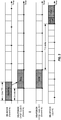
- FIG. 3 shows a timing diagram for the physical channels used for HSDPA.
- a Node B may serve one or more UEs in each TTI.
- the Node B may send signaling for each scheduled UE on the HS-SCCH and may send data on the HS-PDSCH two slots later.
- the Node B may use a configurable number of 128-chip OVSF codes for the HS-SCCH and may use up to fifteen 16-chip OVSF codes for the HS-PDSCH.
- HSDPA may be considered as having a single HS-PDSCH with up to fifteen 16-chip OVSF codes and a single HS-SCCH with a configurable number of 128-chip OVSF codes.
- HSDPA may be considered as having up to fifteen HS-PDSCHs and a configurable number of HS-SCCHs, with each HS-PDSCH having a single 16-chip OVSF code and each HS-SCCH having a single 128-chip OVSF code.
- the following description uses the terminology of a single HS-PDSCH and a single HS-SCCH.
- Each UE that might receive data on the HS-PDSCH may process up to four 128-chip OVSF codes for the HS-SCCH in each TTI to determine whether signaling has been sent for that UE.
- Each UE that is scheduled in a given TTI may process the HS-PDSCH to recover data sent to that UE.
- Each scheduled UE may send either an acknowledgement (ACK) on the HS-DPCCH if a transport block is decoded correctly or a negative acknowledgement (NACK) otherwise.
- ACK acknowledgement
- NACK negative acknowledgement
- Each UE may also send PCI and CQI information on the HS-DPCCH to the Node B.
- FIG. 3 also shows timing offsets between the HS-SCCH, the HS-PDSCH, and the HS-DPCCH at a UE.
- the HS-PDSCH starts two slots after the HS-SCCH.
- the HS-DPCCH starts approximately 7.5 slots from the end of the corresponding transmission on the HS-PDSCH.
- a UE may send CQI information to allow a Node B to appropriately process and transmit data to the UE.
- CQI information may be sent for any number of transport blocks or data streams. For clarity, much of the description below assumes that one or two transport blocks may be sent in a given TTI and that the CQI information may be for one or two transport blocks.
- the Node B may transmit two transport blocks to the UE using one of multiple possible precoding matrices or may transmit a single transport block using one column/vector of one of the possible precoding matrices.
- the UE may evaluate data performance for different possible precoding matrices and vectors that can be used by the Node B for data transmission to the UE.
- the UE may estimate the quality of each transport block, which may be given by any suitable metric.
- SINR additive white Gaussian noise
- the UE may determine data performance (e.g., the overall throughput) for each precoding matrix or vector based on the SINR(s) of all transport block(s). After evaluating all possible precoding matrices and vectors, the UE may select the precoding matrix or vector that provides the best data performance.
- data performance e.g., the overall throughput
- the UE may estimate the SINRs of two transport blocks that may be sent in parallel with that precoding matrix.
- the transport block with the higher SINR may be referred to as the primary transport block, and the transport block with the lower SINR may be referred to as the secondary transport block.
- the SINR of each transport block may be dependent on various factors such as (i) the total power of the HS-PDSCH, (ii) the number of OVSF codes used for the HS-PDSCH, (iii) channel conditions, which may be given by channel gains and noise variance, (iv) the type of receiver processing performed by the UE, (v) the order in which the transport blocks are recovered if successive interference cancellation (SIC) is performed by the UE, and (vi) possibly other factors.
- SIC successive interference cancellation
- SINR i F P OVSF X i ,
- the SINR function may be dependent on the receiver processing at the UE and may not be a linear function of P OVSF .
- P OVSF increases by G decibel (dB)
- the amount of improvement in SINR may not be accurately known based solely on the G dB increase in P OVSF .
- This non-linear relationship between P OVSF and SINR may be due to code-reuse interference, which is interference between two transport blocks using the same OVSF codes.
- the SINR function may not be known at the Node B.
- the Node B may send power information that may be used by the UE to determine the power per OVSF code, P OVSF , to use for SINR estimation.
- the power information may be given in various forms and may be based on certain assumptions.
- the power information comprises a power offset that is indicative of the difference between the power of the HS-PDSCH, P HSPDSCH , and the power of a reference channel.
- the reference channel may be a Common Pilot Channel (CPICH) or some other channel having known power.
- CPICH Common Pilot Channel
- the Node B may signal the power offset ⁇ to the UE, as described below.
- P HSPDSCH is the transmit power of the HS-PDSCH
- P CPICH is the transmit power of the CPICH.
- P HSPDSCH is the received power of the HS-PDSCH
- P CPICH is the received power of the CPICH.
- the UE may be able to determine P HSPDSCH based on the signaled power offset ⁇ , as shown in equation (2).
- the Node B and UE may compute P OVSF in the same manner based on the available information so that the power per OVSF code used by the Node B for data transmission can meet or exceed the P OVSF used by the UE for SINR estimation.
- P OVSF may be computed in various manners. In one design, P HSPDSCH may be distributed evenly to all transport blocks, and P OVSF may then be the same for all transport blocks. In another design, a particular percentage of P HSPDSCH may be distributed to the primary transport block, the remaining percentage of P HSPDSCH may be distributed to the secondary transport block, and P OVSF may be different for the two transport blocks.
- P OVSF may be computed based on a designated number of OVSF codes, M.
- the Node B may provide M via higher layer signaling and/or some other mechanism, e.g., on a regular basis or whenever there is a change.
- Table 2 lists some parameters used in the description herein and provides a short description for each parameter.
- Table 2 Symbol Description P HSPDSCH Power computed by the UE and Node B based on the power offset r and P CPICH , which are known to both entities. P ⁇ HSPDSCH Power available at the Node for the HS-PDSCH. P OVSF Power per OVSF code computed by the UE and Node B based on the power offset r and P CPICH . P ⁇ OVSF Power per OVSF code available at the Node B for the HS-PDSCH.
- P HSPDSCH may be equal to, less than, or greater than P ⁇ HSPDSCH .
- P HSPDSCH and P OVSF may be referred to as signaled or computed values, and P ⁇ HSPDSCH and P ⁇ OVSF may be referred to as available values.
- the Node B may have K OVSF codes available for the HS-PDSCH, where K may or may not be equal to the designated number of OVSF codes.
- the Node B may scale the power offset r based on the number of available OVSF codes and the designated number of OVSF codes.
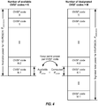
- FIG. 4 shows scaling of the power offset by the Node B.
- the Node B may have K available OVSF codes for the HS-PDSCH, where 1 ⁇ K ⁇ M for the example shown in FIG. 4 .
- the Node B may also have P ⁇ HSPDSCH available for the HS-PDSCH.
- the Node B may set P OVSF equal to P ⁇ OVSF .
- the computed P HSPDSCH may be larger than the available P ⁇ HSPDSCH at the Node B. If K is greater than M (not shown in FIG. 4 ), then the computed P HSPDSCH may be smaller than the available P ⁇ HSPDSCH .
- the power offset ⁇ may be considered as a virtual or hypothetical power offset used for computation of P OVSF based on the designated number of OVSF codes.
- the Node B may send the power information used to determine P OVSF in various manners.
- the Node B may send the power information via higher layer signaling and/or some other mechanism, e.g., on a regular basis or whenever there is a change.
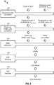
- FIG. 5 shows a mechanism for sending the power offset ⁇ using a Radio Resource Control (RRC) message in UMTS.
- the Node B may send a PHYSICAL CHANNEL RECONFIGURATION message to the UE in order to assign, replace or release a set of physical channels used by the UE.
- This message may include a number of information elements (IEs), one of which may be a Downlink HS-PDSCH Information IE that may carry information for the HS-PDSCH.
- the Downlink HS-PDSCH Information IE may include a Measurement Feedback Info IE that may carry information affecting feedback information sent by the UE on the uplink to the Node B.
- the Measurement Feedback Info IE may include a Measurement Power Offset parameter, which may be set to the power offset ⁇ computed as shown in equation (6).
- the power offset r may also be sent in other RRC messages to the UE.
- the RRC messages and IEs are described in 3GPP TS 25.331, entitled “Radio Resource Control (RRC),” dated September 2007, which is publicly available.
- the Node B may also send the power offset ⁇ in other manners.
- the Node B may also send other types of information to allow the UE to compute P OVSF .
- the Node B may send a relative value (e.g., the power offset) or an absolute value (e.g., P HSPDSCH ) for the computation of P OVSF .
- the Node B may send the power information when a link for the UE is set up, is changed, etc.
- the UE may receive the power information (e.g., the power offset) from the Node B and may compute P OVSF based on the power information and other known information. The UE may then use P OVSF to determine CQI information.
- the power information e.g., the power offset
- FIG. 6 shows a process 600 for determining CQI information for multiple (e.g., two) transport blocks.
- the UE may compute the received power of the HS-PDSCH, P HSPDSCH , based on the power offset ⁇ received from the Node B and the received power of the CPICH, P CPICH , e.g., as shown in equation (2) (block 610).
- the UE may next compute P OVSF based on P HSPDSCH and the designated number of OVSF codes, e.g., as shown in equation (3) (block 612).
- the UE may estimate the SINR of each transport block based on P OVSF and other parameters and in accordance with an SINR function (block 614).
- the UE may map the SINR of each transport block to a CQI index based on a CQI mapping table (block 616).
- the CQI mapping table may have L entries for L possible CQI levels, where L may be any suitable value.
- Each CQI level may be associated with a set of parameters for a transport block as well as a required SINR.
- the set of parameters may include a transport block size, a modulation scheme, a code rate, etc.
- the L CQI levels may be associated with increasing required SINRs.
- the UE may select the highest CQI level with a required SINR that is lower than the estimated SINR of that transport block.
- the CQI index for each transport block may indicate one of L possible CQI levels.
- the UE may send the CQI indices to the Node B (block 618).
- the Node B may transmit transport blocks to the UE based on the CQI indices received from the UE.
- symmetric OVSF code allocation is employed, and the same number and same set of OVSF codes is used for two transport blocks.
- the CQI mapping table may be defined such that the same number of OVSF codes is used for all CQI levels.
- asymmetric OVSF code allocation is allowed, and the number of OVSF codes for the secondary transport block may be different (e.g., fewer) than the number of OVSF codes for the primary transport block.
- the CQI mapping table may have different numbers of OVSF codes for different CQI levels, e.g., fewer OVSF codes for one or more of the lowest CQI levels.
- the secondary transport block may be sent with a subset of the OVSF codes used for the primary transport block.
- a CQI value within a range of 0 through 30 is used to convey a CQI index for one transport block
- a CQI value within a range of 31 through 255 is used to convey two CQI indices for two transport blocks.
- the UE may also map the CQI index or indices for one or two transport blocks to a single CQI value in other manners.
- the UE may send a PCI/CQI report that may include two bits for PCI information and 8 bits for CQI information.
- the PCI information may convey a precoding matrix or vector selected by the UE.
- the CQI information may comprise one 8-bit CQI value computed as shown in equation (7).
- the ten bits for the PCI/CQI report may be channel encoded with a (20, 10) block code to obtain a codeword of 20 code bits.
- the 20 code bits for the PCI/CQI report may be spread and sent on the HS-DPCCH in the second and third slots of the TTI, which are labeled as "CQI" in FIG. 3 .
- the Node B may receive the PCI/CQI report from the UE and determine whether the UE prefers one or two transport blocks and the CQI index for each preferred transport block based on the reported CQI value.
- the Node B may transmit the number of transport blocks preferred by the UE or fewer transport blocks. For example, if the UE prefers two transport blocks, then the Node B may transmit zero, one, or two transport blocks to the UE.
- the UE may determine the CQI index for each transport block based on P OVSF , which may be obtained based on the designated number of OVSF codes, M.
- the Node B may have K OVSF codes available for the HS-PDSCH, where K may or may not be equal to M.
- the Node B may transmit data to the UE in various manners depending on K, M, P OVSF and the available P ⁇ HSPDSCH at the Node B.
- the Node B may transmit each transport block with the K available OVSF codes at P OVSF or higher to the UE.
- the Node B may scale up P OVSF by a factor of up to M / K and may then transmit a transport block of size S or larger at the higher P OVSF to the UE.
- the Node B may predict the improvement in SINR with the higher P OVSF and may select the transport block size accordingly.
- the Node B may scale up the transport block size by a factor of K / M and may transmit a transport block of a larger size of K ⁇ S/M with the K available OVSF codes at P OVSF or higher to the UE.
- the Node B may scale down P OVSF by a factor of up to M / K and may then transmit a transport block of size S or smaller at the lower P OVSF to the UE.
- the Node B may select the number of OVSF codes to use for the HS-PDSCH based on K, M, P ⁇ HSPDSCH and P HSPDSCH such that P OVSF or higher can be used for each OVSF code.
- the Node B may transmit each transport block with up to K available OVSF codes at P OVSF or higher.
- the Node B may scale the transport block size based on the number of OVSF codes used for the HS-PDSCH and the designated number of OVSF codes used to determine CQI.
- FIG. 7 shows a design of a process 700 performed by the Node B (or a transmitter).
- Power information indicative of total power, P HSPDSCH , for a designated number of channelization codes, M, with equal power per channelization code, P OVSF may be determined (block 712).
- the power information may comprise a power offset between the total power for the designated number of channelization codes for a data channel and the power of a pilot channel, P CPICH .
- the designated number of channelization codes may be the maximum number of channelization codes available for data transmission, which is 15 for the HS-PDSCH.
- the designated number of channelization codes may also be a fixed number of channelization codes that is known a priori by the UE.
- the power available for the data channel, P ⁇ HSPDSCH , and the number of channelization codes available for the data channel, K may be determined.
- the power per channelization code, P ⁇ OVSF , for the number of available channelization codes may be determined based on the available power, P ⁇ HSPDSCH .
- the total power of the data channel, P HSPDSCH may then be computed based on the designated number of channelization codes and the power per channelization code, P ⁇ OVSF , e.g., as shown in equation (5).
- the power offset may then be determined based on the total power of the data channel, P HSPDSCH , and the power of the pilot channel, P CPICH , e.g., as shown in equation (6).
- the total power P HSPDSCH determined based on the power information may be greater than or less than the available power P ⁇ HSPDSCH .
- the power information may be sent to the UE, e.g., in an RRC message or via some other means (block 714).
- At least one CQI index for at least one transport block may be received from the UE, with the at least one CQI index being determined by the UE based on the power per channelization code, P OVSF (block 716).
- At least one transport block may be sent to the UE based on the at least one received CQI index (block 718).
- the transport block(s) may be sent with the designated number of channelization codes and at the power per channelization code, P OVSF , or higher to the UE.
- the transport block(s) may be scaled based on the designated number of channelization codes and the number of available channelization codes.
- the transport block(s) may then be sent with the number of available channelization codes and at the power per channelization code, P OVSF , or higher to the UE.
- the power per channelization code may be scaled based on the designated number of channelization codes and the number of available channelization codes.
- the transport block(s) may then be sent with the number of available channelization codes and at the scaled power per channelization code to the UE.
- FIG. 8 shows a design of a process 800 performed by the UE (or a receiver).
- Power information may be received from the Node B, e.g., in an RRC message or via some other means (block 812).
- a power per channelization code, P OVSF for a designated number of channelization codes may be determined based on the power information (block 814).
- a power offset may be obtained from the power information, and the received power of a data channel, P HSPDSCH , may be determined based on the power offset and the received power of a pilot channel, P CPICH , e.g., as shown in equation (2).
- the power per channelization code, P OVSF may then be determined based on the received power of the data channel, P HSPDSCH , and the designated number of channelization codes, e.g., as shown in equation (3).
- At least one CQI index for at least one transport block may be determined based on the power per channelization code (block 816).
- at least one SINR of at least one transport block may be estimated based on the power per channelization code.
- At least one CQI index for at least one transport block may then be determined based on the at least one SINR and may be sent to the Node B (block 818).
- At least one transport block may be received from the Node B, with the transport block(s) being transmitted at the power per channelization code, P OVSF , or higher by the Node B (block 820).
- the transport block(s) may be received via a number of available channelization codes and may have size scaled based on the designated number of channelization codes and the number of available channelization codes.
- a Node B may determine power information indicative of total power for a designated number of resource elements with equal power per resource element.
- the designated number of resource elements may correspond to a designated number of subcarriers, a designated number of channelization codes, a designated number of time slots, a designated number of data streams, a designated number of transport blocks, a designated number of channels, a designated number of antennas, etc.
- the Node B may send the power information to a UE and may send data with one or more resource elements and at the power per resource element or higher to the UE.
- DSP digital signal processor
- ASIC application specific integrated circuit
- FPGA field programmable gate array
- a general-purpose processor may be a microprocessor, but in the alternative, the processor may be any conventional processor, controller, microcontroller, or state machine.
- a processor may also be implemented as a combination of computing devices, e.g., a combination of a DSP and a microprocessor, a plurality of microprocessors, one or more microprocessors in conjunction with a DSP core, or any other such configuration.
- a software module may reside in RAM memory, flash memory, ROM memory, EPROM memory, EEPROM memory, registers, hard disk, a removable disk, a CD-ROM, or any other form of storage medium known in the art.
- An exemplary storage medium is coupled to the processor such that the processor can read information from, and write information to, the storage medium.
- the storage medium may be integral to the processor.
- the processor and the storage medium may reside in an ASIC.
- the ASIC may reside in a user terminal.
- the processor and the storage medium may reside as discrete components in a user terminal.
- the functions described may be implemented in hardware, software, firmware, or any combination thereof. If implemented in software, the functions may be stored on or transmitted over as one or more instructions or code on a computer-readable medium.
- Computer-readable media includes both computer storage media and communication media including any medium that facilitates transfer of a computer program from one place to another.
- a storage media may be any available media that can be accessed by a general purpose or special purpose computer.
- such computer-readable media can comprise RAM, ROM, EEPROM, CD-ROM or other optical disk storage, magnetic disk storage or other magnetic storage devices, or any other medium that can be used to carry or store desired program code means in the form of instructions or data structures and that can be accessed by a general-purpose or special-purpose computer, or a general-purpose or special-purpose processor. Also, any connection is properly termed a computer-readable medium.
- Disk and disc includes compact disc (CD), laser disc, optical disc, digital versatile disc (DVD), floppy disk and blu-ray disc where disks usually reproduce data magnetically, while discs reproduce data optically with lasers. Combinations of the above should also be included within the scope of computer-readable media.
- an apparatus for wireless communication comprising:
- the power information may comprise a power offset between the total power for the designated number of channelization codes for a data channel and power of a pilot channel.
- the designated number of channelization codes may be greater than number of available channelization codes, and wherein the total power for the designated number of channelization codes may be greater than available power for a data channel.
- the at least one processor may be configured to determine power available for a data channel, to determine number of channelization codes available for the data channel, and to determine the power information based on the available power, the number of available channelization codes, and the designated number of channelization codes.
- the at least one processor may be configured to determine the power per channelization code based on the available power and the number of available channelization codes, to compute the total power for the designated number of channelization codes based on the designated number of channelization codes, the number of available channelization codes, and the power per channelization code, and to determine the power information based on the total power for the designated number of channelization codes.
- the at least one processor may be configured to determine a power offset based on the total power for the designated number of channelization codes and power of a pilot channel, and wherein the power information comprises the power offset.
- the at least one processor may be configured to receive at least one channel quality indicator (CQI) index for at least one transport block from the UE, the at least one CQI index being determined by the UE based on the power per channelization code, and to send the at least one transport block to the UE based on the at least one CQI index.
- CQI channel quality indicator
- the at least one processor may be configured to send the at least one transport block with the designated number of channelization codes and at the power per channelization code or higher to the UE.
- the at least one processor may be configured to scale size of the at least one transport block based on the designated number of channelization codes and number of available channelization codes, and to send the at least one transport block with the number of available channelization codes and at the power per channelization code or higher to the UE.
- the at least one processor may be configured to scale the power per channelization code based on the designated number of channelization codes and number of available channelization codes, and to send the at least one transport block with the number of available channelization codes and at the scaled power per channelization code to the UE.
- the at least one processor may be configured to send each of multiple transport blocks with a common set of channelization codes.
- the at least one processor may be configured to send a first transport block with a set of channelization codes, and to send a second transport block with a subset of the set of channelization codes used for the first transport block.
- the designated number of channelization codes may be a maximum number of channelization codes available for data transmission.
- the designated number of channelization codes may be a fixed number of channelization codes available for data transmission and known a priori by the UE.
- the at least one processor may be configured to send the power information in an information element in a Radio Resource Control (RRC) message to the UE.
- RRC Radio Resource Control
- a method for wireless communication comprising:
- the determining the power information may comprise
- the determining the power information may comprise
- the method may further comprise:
- the method may further comprise:
- an apparatus for wireless communication comprising:
- the means for determining the power information may comprise
- the means for determining the power information may comprise
- the apparatus may further comprise:
- the apparatus may further comprise:
- a computer program product comprising:
- an apparatus for wireless communication comprising:
- the at least one processor may be configured to receive at least one channel quality indicator (CQI) index for at least one transport block from the UE, the at least one CQI index being determined by the UE based on the power per OVSF code, to process the at least one transport block based on the at least one CQI index, and to send the at least one transport block with 15 OVSF codes and at the power per OVSF code or higher to the UE.
- CQI channel quality indicator
- the at least one processor may be configured to receive at least one channel quality indicator (CQI) index for at least one transport block from the UE, the at least one CQI index being determined by the UE based on the power per OVSF code, to scale size of the at least one transport block based on the 15 OVSF codes indicative of the power per OVSF code and number of available OVSF codes, to process the at least one transport block based on the at least one CQI index, and to send the at least one transport block with the number of available OVSF codes and at the power per OVSF code or higher to the UE.
- CQI channel quality indicator
- an apparatus for wireless communication comprising:
- the designated number of resource elements may comprise a designated number of subcarriers, a designated number of channelization codes, a designated number of time slots, a designated number of data streams, a designated number of transport blocks, a designated number of channels, or a designated number of antennas.
- the at least one processor may be configured to send data with one or more resource elements and at the power per resource element or higher to the UE.
- an apparatus for wireless communication comprising:
- the at least one processor may be configured to obtain a power offset from the power information, to determine received power of a data channel based on the power offset and received power of a pilot channel, and to determine the power per channelization code based on the received power of the data channel and the designated number of channelization codes.
- the at least one processor may be configured to estimate at least one signal-to-interference-and-noise ratio (SINR) of the at least one transport block based on the power per channelization code, and to determine the at least one CQI index for the at least one transport block based on the at least one SINR.
- SINR signal-to-interference-and-noise ratio
- the at least one processor may be configured to receive the at least one transport block transmitted by the Node B at the power per channelization code or higher.
- the at least one processor may be configured to receive the at least one transport block via a number of available channelization codes from the Node B, the at least one transport block having size scaled based on the designated number of channelization codes and the number of available channelization codes.
- a method for wireless communication comprising:
- the determining the power per channelization code may comprise obtaining a power offset from the power information, determining received power of a data channel based on the power offset and received power of a pilot channel, and determining the power per channelization code based on the received power of the data channel and the designated number of channelization codes.
- the determining the at least one CQI index may comprise estimating at least one signal-to-interference-and-noise ratio (SINR) of the at least one transport block based on the power per channelization code, and determining the at least one CQI index for the at least one transport block based on the at least one SINR.
- SINR signal-to-interference-and-noise ratio
- the method may further comprise:
- an apparatus for wireless communication comprising:
- the means for determining the power per channelization code may comprise means for obtaining a power offset from the power information, means for determining received power of a data channel based on the power offset and received power of a pilot channel, and means for determining the power per channelization code based on the received power of the data channel and the designated number of channelization codes.
- the means for determining the multiple CQI indices may comprise means for estimating at least one signal-to-interference-and-noise ratio (SINR) of the at least one transport block based on the power per channelization code, and means for determining the at least one CQI index for the at least one transport block based on the at least one SINR.
- SINR signal-to-interference-and-noise ratio
- the apparatus may further comprise:
Description
- The present disclosure relates generally to communication, and more specifically to techniques for signaling power information in a wireless communication system.
- In a wireless communication system, a Node B may utilize multiple (T) transmit antennas for data transmission to a user equipment (UE) equipped with multiple (R) receive antennas. The multiple transmit and receive antennas form a multiple-input multiple-output (MIMO) channel that may be used to increase throughput and/or improve reliability. For example, the Node B may transmit up to T data streams simultaneously from the T transmit antennas to improve throughput. Alternatively, the Node B may transmit a single data stream from all T transmit antennas to improve reception quality by the UE. Each data stream may carry one transport block of data in a given transmission time interval (TTI). Hence, the terms "data stream" and "transport block" may be used interchangeably.
- Good performance (e.g., high throughput) may be achieved by sending each transport block at the highest possible rate that still allows the UE to reliably decode the transport block. The UE may estimate signal-to-interference-and-noise ratios (SINRs) of each possible precoding combination of transport blocks that might be transmitted and may then determine channel quality indicator (CQI) information based on the estimated SINRs of the best precoding combination of transport blocks. The CQI information may convey a set of processing parameters for each transport block. The UE may send the CQI information to the Node B. The Node B may process one or more transport blocks in accordance with the CQI information and send the transport block(s) to the UE.
- Data transmission performance may be dependent on accurate determination and reporting of CQI information by the UE. There is therefore a need in the art for techniques to facilitate accurate determination and reporting of CQI information. "CQI Reporting for FDD MIMO", R1-070513, 3GPP, 10 January 2007, discusses a scheme for defining CQI vales of type A CQI reports in support of FDD MIMO. "Definition of MIMO operation on HS-PDSCH, preferred precoding and CQI reporting procedures, modified CQI tables" R1-070514, 3GPP, 10 January 2007, relates to definition of details on the D-TxAA transmit processing and the procedure to produce composite PCI/CQI reports in caser the UE is configured in MIMO mode.
- The present invention relates to methods and apparatuses for wireless communication as defined in the appended claims.
- Techniques for signaling power information to facilitate accurate determination and reporting of CQI information for a MIMO transmission are described herein. For a MIMO transmission sent using code division multiplexing, the SINR of a transport block may be dependent on power per channelization code, POVSF , but may not be a linear function of POVSF.
- In an aspect, a Node B may send power information that may be used by a UE to determine POVSF , which may then be used for SINR estimation. In one design, the power information comprises a power offset between the power of a data channel, PHSPDSCH , and the power of a pilot channel, PCPICH. In general, the data channel may comprise any number of channelization codes. PHSPDSCH may be given for a designated number of channelization codes, M, which may be a known value or provided via signaling. The Node B may determine PHSPDSCH based on the power available for the data channel, P̃HSPDSCH, the number of channelization codes available for the data channel, K, and the designated number of channelization codes, M. PHSPDSCH may be greater than P̃HSPDSCH if the designated number of channelization codes is greater than the number of available channelization codes.
- The UE may receive the power information from the Node B and may determine POVSF based on the power information and the designated number of channelization codes. In one design, the UE may obtain the power offset from the power information and compute PHSPDSCH based on the power offset and the known PCPICH. The UE may then distribute PHSPDSCH across at least one transport block and also across the designated number of channelization codes to obtain POVSF. The UE may estimate the SINR of each transport block based on POVSF and then determine CQI information for the at least one transport block based on the SINR of each transport block. The UE may send the CQI information to the Node B.
- The Node B may receive the CQI information from the UE and may send at least one transport block in a MIMO transmission to the UE. In one design, the Node B may send the transport block(s) with the designated number of channelization codes and at POVSF or higher. In another design, the Node B may send the transport block(s) with K available channelization codes at POVSF or higher and may scale the size of the transport block(s) based on the designated number of channelization codes, M, and the number of available channelization codes, K. In yet another design, the Node B may scale POVSF based on K and M and may then send the transport block(s) with the K available channelization codes at the scaled POVSF.
- Various aspects and features of the disclosure are described in further detail below.
-
-
FIG. 1 shows a wireless communication system. -
FIG. 2 shows a block diagram of a Node B and a UE. -
FIG. 3 shows a timing diagram for a set of physical channels. -
FIG. 4 shows scaling of the power offset by the Node B. -
FIG. 5 shows a mechanism for sending the power offset by the Node B. -
FIG. 6 shows a process for determining CQI information by the UE. -
FIG. 7 shows a process performed by the Node B. -
FIG. 8 shows a process performed by the UE. - The techniques described herein may be used for various wireless communication systems such as Code Division Multiple Access (CDMA) systems, Time Division Multiple Access (TDMA) systems, Frequency Division Multiple Access (FDMA) systems, Orthogonal FDMA (OFDMA) systems, Single-Carrier FDMA (SC-FDMA) systems, etc. The terms "system" and "network" are often used interchangeably. A CDMA system may implement a radio technology such Universal Terrestrial Radio Access (UTRA), cdma2000, etc. UTRA includes Wideband-CDMA (W-CDMA) and other CDMA variants. cdma2000 covers IS-2000, IS-95 and IS-856 standards. UTRA is part of Universal Mobile Telecommunication System (UMTS), and both are described in documents from an organization named "3rd Generation Partnership Project" (3GPP). cdma2000 is described in documents from an organization named "3rd Generation Partnership Project 2" (3GPP2). These various radio technologies and standards are known in the art. For clarity, the techniques are described below for UMTS, and UMTS terminology is used in much of the description below.
-
FIG. 1 shows awireless communication system 100 withmultiple Node Bs 110 andmultiple UEs 120.System 100 may also be referred to as a Universal Terrestrial Radio Access Network (UTRAN) in UMTS. A Node B is generally a fixed station that communicates with the UEs and may also be referred to as an evolved Node B (eNode B), a base station, an access point, etc. Each NodeB 110 provides communication coverage for a particular geographic area and supports communication for the UEs located within the coverage area. Asystem controller 130 couples to NodeBs 110 and provides coordination and control for these Node Bs.System controller 130 may be a single network entity or a collection of network entities. - UEs 120 may be dispersed throughout the system, and each UE may be stationary or mobile. A UE may also be referred to as a mobile station, a terminal, an access terminal, a subscriber unit, a station, etc. A UE may be a cellular phone, a personal digital assistant (PDA), a wireless device, a handheld device, a wireless modem, a laptop computer, etc.
-
FIG. 2 shows a block diagram of a design of oneNode B 110 and oneUE 120. In this design,Node B 110 is equipped with multiple (T)antennas 220a through 220t, andUE 120 is equipped with multiple (R)antennas 252a through 252r. A MIMO transmission may be sent from the T transmit antennas atNode B 110 to the R receive antennas atUE 120. - At
Node B 110, a transmit (TX) data and signalingprocessor 212 may receive data from a data source (not shown) for all scheduled UEs.Processor 212 may process (e.g., format, encode, interleave, and symbol map) the data for each UE and provide data symbols, which are modulation symbols for data.Processor 212 may also process signaling (e.g., power information) and provides signaling symbols, which are modulation symbols for signaling. Aspatial mapper 214 may precode the data symbols for each UE based on a precoding matrix or vector for that UE and provide output symbols for all UEs. A CDMA modulator (MOD) 216 may perform CDMA processing on the output symbols and signaling symbols and may provide T output chip streams to T transmitters (TMTR) 218a through 218t. Each transmitter 218 may process (e.g., convert to analog, filter, amplify, and frequency upconvert) its output chip stream and provide a downlink signal. T downlink signals fromT transmitters 218a through 218t may be sent viaT antennas 220a through 220t, respectively. - At
UE 120,R antennas 252a through 252r may receive the downlink signals fromNode B 110 and provide R received signals to R receivers (RCVR) 254a through 254r, respectively. Each receiver 254 may process (e.g., filter, amplify, frequency downconvert, and digitize) its received signal and provide samples to achannel processor 268 and an equalizer/CDMA demodulator (DEMOD) 260.Processor 268 may derive coefficients for a front-end filter/equalizer and coefficients for one or more combiner matrices for equalizer/CDMA demodulator 260.Unit 260 may perform equalization with the front-end filter and CDMA demodulation and may provide filtered symbols. AMIMO detector 262 may combine the filtered symbols across spatial dimension and provide detected symbols, which are estimates of the data symbols and signaling symbols sent toUE 120. A receive (RX) data and signalingprocessor 264 may process (e.g., symbol demap, deinterleave, and decode) the detected symbols and provide decoded data and signaling. In general, the processing by equalizer/CDMA demodulator 260,MIMO detector 262, and RX data and signalingprocessor 264 is complementary to the processing byCDMA modulator 216,spatial mapper 214, and TX data and signalingprocessor 212, respectively, atNode B 110. -
Channel processor 268 may estimate the response of the wireless channel fromNode B 110 toUE 120.Processor 268 and/or 270 may process the channel estimate and/or the derived coefficients to obtain feedback information, which may include precoding control indicator (PCI) information and CQI information. The PCI information may convey the number of transport blocks to send in parallel and a specific precoding matrix or vector to use for precoding the transport block(s). A transport block may also be referred to as a packet, a data block, etc. The CQI information may convey processing parameters (e.g., the transport block size and modulation scheme) for each transport block.Processor 268 and/or 270 may evaluate different possible precoding matrices and vectors that can be used for data transmission and may select a precoding matrix or vector that can provide the best performance, e.g., the highest overall throughput.Processor 268 and/or 270 may also determine the CQI information for the selected precoding matrix or vector. - The feedback information and data to send on the uplink may be processed by a TX data and signaling
processor 280, further processed by aCDMA modulator 282, and conditioned bytransmitters 254a through 254r to generate R uplink signals, which may be transmitted viaantennas 252a through 252r, respectively. The number of transmit antennas atUE 120 may or may not be equal to the number of receive antennas. For example,UE 120 may receive data using two antennas but may transmit the feedback information using only one antenna. AtNode B 110, the uplink signals fromUE 120 may be received byantennas 220a through 220t, conditioned byreceivers 218a through 218t, processed by an equalizer/CDMA demodulator 240, detected by aMIMO detector 242, and processed by an RX data and signalingprocessor 244 to recover the feedback information and data sent byUE 120. The number of receive antennas atNode B 110 may or may not match the number of transmit antennas. - Controllers/
processors Node B 110 andUE 120, respectively.Memories Node B 110 andUE 120, respectively. Ascheduler 234 may schedule UEs for downlink and/or uplink transmission, e.g., based on the feedback information received from the UEs. - In UMTS, data for a UE may be processed as one or more transport channels at a higher layer. The transport channels may carry data for one or more services such as voice, video, packet data, etc. The transport channels may be mapped to physical channels at a physical layer. The physical channels may be channelized with different channelization codes and may thus be orthogonal to one another in the code domain. UMTS uses orthogonal variable spreading factor (OVSF) codes as the channelization codes for the physical channels.
- 3GPP Release 5 and later supports High-Speed Downlink Packet Access (HSDPA), which is a set of channels and procedures that enable high-speed packet data transmission on the downlink. For HSDPA, a Node B may send data on a High Speed Downlink Shared Channel (HS-DSCH), which is a downlink transport channel that is shared by all UEs in both time and code. The HS-DSCH may carry data for one or more UEs in each TTI. For UMTS, a 10 millisecond (ms) radio frame is partitioned into five 2-ms subframes, each subframe includes three slots, and each slot has a duration of 0.667 ms. A TTI is equal to one subframe for HSDPA and is the smallest unit of time in which a UE may be scheduled and served. The sharing of the HS-DSCH may change dynamically from TTI to TTI.
- Table 2 lists some downlink and uplink physical channels used for HSDPA and provides a short description for each physical channel.
Table 1 Link Channel Channel Name Description Downlink HS-PDSCH High Speed Physical Downlink Shared Channel Carry data sent on the HS-DSCH for different UEs. Downlink HS-SCCH Shared Control Channel for HS-DSCH Carry signaling for the HS-PDSCH. Uplink HS-DPCCH Dedicated Physical Control Channel for HS-DSCH Carry feedback for downlink transmission in HSDPA. -
FIG. 3 shows a timing diagram for the physical channels used for HSDPA. For HSDPA, a Node B may serve one or more UEs in each TTI. The Node B may send signaling for each scheduled UE on the HS-SCCH and may send data on the HS-PDSCH two slots later. The Node B may use a configurable number of 128-chip OVSF codes for the HS-SCCH and may use up to fifteen 16-chip OVSF codes for the HS-PDSCH. HSDPA may be considered as having a single HS-PDSCH with up to fifteen 16-chip OVSF codes and a single HS-SCCH with a configurable number of 128-chip OVSF codes. Equivalently, HSDPA may be considered as having up to fifteen HS-PDSCHs and a configurable number of HS-SCCHs, with each HS-PDSCH having a single 16-chip OVSF code and each HS-SCCH having a single 128-chip OVSF code. The following description uses the terminology of a single HS-PDSCH and a single HS-SCCH. - Each UE that might receive data on the HS-PDSCH may process up to four 128-chip OVSF codes for the HS-SCCH in each TTI to determine whether signaling has been sent for that UE. Each UE that is scheduled in a given TTI may process the HS-PDSCH to recover data sent to that UE. Each scheduled UE may send either an acknowledgement (ACK) on the HS-DPCCH if a transport block is decoded correctly or a negative acknowledgement (NACK) otherwise. Each UE may also send PCI and CQI information on the HS-DPCCH to the Node B.
-
FIG. 3 also shows timing offsets between the HS-SCCH, the HS-PDSCH, and the HS-DPCCH at a UE. The HS-PDSCH starts two slots after the HS-SCCH. The HS-DPCCH starts approximately 7.5 slots from the end of the corresponding transmission on the HS-PDSCH. - A UE may send CQI information to allow a Node B to appropriately process and transmit data to the UE. In general, CQI information may be sent for any number of transport blocks or data streams. For clarity, much of the description below assumes that one or two transport blocks may be sent in a given TTI and that the CQI information may be for one or two transport blocks.
- The Node B may transmit two transport blocks to the UE using one of multiple possible precoding matrices or may transmit a single transport block using one column/vector of one of the possible precoding matrices. The UE may evaluate data performance for different possible precoding matrices and vectors that can be used by the Node B for data transmission to the UE. For each precoding matrix or vector, the UE may estimate the quality of each transport block, which may be given by any suitable metric. For clarity, the following description assumes that the quality of each transport block is given by an equivalent SINR for an additive white Gaussian noise (AWGN) channel, which is referred to as simply SINR in the description below. The UE may determine data performance (e.g., the overall throughput) for each precoding matrix or vector based on the SINR(s) of all transport block(s). After evaluating all possible precoding matrices and vectors, the UE may select the precoding matrix or vector that provides the best data performance.
- For each possible precoding matrix, the UE may estimate the SINRs of two transport blocks that may be sent in parallel with that precoding matrix. The transport block with the higher SINR may be referred to as the primary transport block, and the transport block with the lower SINR may be referred to as the secondary transport block. The SINR of each transport block may be dependent on various factors such as (i) the total power of the HS-PDSCH, (ii) the number of OVSF codes used for the HS-PDSCH, (iii) channel conditions, which may be given by channel gains and noise variance, (iv) the type of receiver processing performed by the UE, (v) the order in which the transport blocks are recovered if successive interference cancellation (SIC) is performed by the UE, and (vi) possibly other factors.
- The SINR of transport block i, SINR i , may be given as:

- where POVSF is the power per OVSF code for the HS-PDSCH,
- X i includes all other parameters that affect SINR, and
- F( ) is an SINR function applicable for the UE.
- The SINR function may be dependent on the receiver processing at the UE and may not be a linear function of POVSF. Thus, if POVSF increases by G decibel (dB), then the amount of improvement in SINR may not be accurately known based solely on the G dB increase in POVSF. This non-linear relationship between POVSF and SINR may be due to code-reuse interference, which is interference between two transport blocks using the same OVSF codes. Furthermore, the SINR function may not be known at the Node B.
- In an aspect, the Node B may send power information that may be used by the UE to determine the power per OVSF code, POVSF, to use for SINR estimation. The power information may be given in various forms and may be based on certain assumptions. In one design, the power information comprises a power offset that is indicative of the difference between the power of the HS-PDSCH, PHSPDSCH , and the power of a reference channel. The reference channel may be a Common Pilot Channel (CPICH) or some other channel having known power. In one design, the power of the HS-PDSCH, PHSPDSCH , may be determined as follows:

- where PCPICH is the power of the CPICH, and
- r is the power offset that may be signaled by the Node B.
- The Node B may signal the power offset Γ to the UE, as described below. At the Node B, PHSPDSCH is the transmit power of the HS-PDSCH, and PCPICH is the transmit power of the CPICH. At the UE, PHSPDSCH is the received power of the HS-PDSCH, and PCPICH is the received power of the CPICH. The UE may be able to determine PHSPDSCH based on the signaled power offset Γ, as shown in equation (2).
- The Node B and UE may compute POVSF in the same manner based on the available information so that the power per OVSF code used by the Node B for data transmission can meet or exceed the POVSF used by the UE for SINR estimation. POVSF may be computed in various manners. In one design, PHSPDSCH may be distributed evenly to all transport blocks, and POVSF may then be the same for all transport blocks. In another design, a particular percentage of PHSPDSCH may be distributed to the primary transport block, the remaining percentage of PHSPDSCH may be distributed to the secondary transport block, and POVSF may be different for the two transport blocks.
- In one design, POVSF may be computed based on a designated number of OVSF codes, M. In one design, the Node B may provide M via higher layer signaling and/or some other mechanism, e.g., on a regular basis or whenever there is a change. In another design, M may be equal to the maximum number of OVSF codes for the HS-PDSCH (i.e., M =15) or equal to some other predetermined/ known value. In any case, POVSF may be obtained by uniformly distributing PHSPDSCH across the M OVSF codes, as follows:

- In equation (3), subtraction in dB is equivalent to division in linear unit.
- Table 2 lists some parameters used in the description herein and provides a short description for each parameter.
Table 2 Symbol Description PHSPDSCH Power computed by the UE and Node B based on the power offset r and PCPICH , which are known to both entities. P̃HSPDSCH Power available at the Node for the HS-PDSCH. POVSF Power per OVSF code computed by the UE and Node B based on the power offset r and PCPICH. P̃OVSF Power per OVSF code available at the Node B for the HS-PDSCH. - In general, PHSPDSCH may be equal to, less than, or greater than P̃HSPDSCH. PHSPDSCH and POVSF may be referred to as signaled or computed values, and P̃HSPDSCH and P̃OVSF may be referred to as available values.
- The Node B may have K OVSF codes available for the HS-PDSCH, where K may or may not be equal to the designated number of OVSF codes. The Node B may scale the power offset r based on the number of available OVSF codes and the designated number of OVSF codes.
-
FIG. 4 shows scaling of the power offset by the Node B. The Node B may have K available OVSF codes for the HS-PDSCH, where 1 ≤ K < M for the example shown inFIG. 4 . The Node B may also have P̃HSPDSCH available for the HS-PDSCH. The Node B may compute P̃OVSF by distributing P̃HSPDSCH uniformly across K available OVSF codes, as follows:
- The Node B may set POVSF equal to P̃OVSF. The Node B may then compute P̃HSPDSCH such that POVSF is obtained for each of the M designated OVSF codes, as follows:

- The Node B may then compute the power offset based on the computed PHSPDSCH and the known PCPICH, as follows:

- If K is less than M, as shown in
FIG. 4 , then the computed PHSPDSCH may be larger than the available P̃HSPDSCH at the Node B. If K is greater than M (not shown inFIG. 4 ), then the computed PHSPDSCH may be smaller than the available P̃HSPDSCH . In any case, since P̃HSPDSCH may or may not be equal to PHSPDSCH , the power offset Γ may be considered as a virtual or hypothetical power offset used for computation of POVSF based on the designated number of OVSF codes. - The Node B may send the power information used to determine POVSF in various manners. In one design, the Node B may send the power information via higher layer signaling and/or some other mechanism, e.g., on a regular basis or whenever there is a change.
-
FIG. 5 shows a mechanism for sending the power offset Γ using a Radio Resource Control (RRC) message in UMTS. The Node B may send a PHYSICAL CHANNEL RECONFIGURATION message to the UE in order to assign, replace or release a set of physical channels used by the UE. This message may include a number of information elements (IEs), one of which may be a Downlink HS-PDSCH Information IE that may carry information for the HS-PDSCH. The Downlink HS-PDSCH Information IE may include a Measurement Feedback Info IE that may carry information affecting feedback information sent by the UE on the uplink to the Node B. The Measurement Feedback Info IE may include a Measurement Power Offset parameter, which may be set to the power offset Γ computed as shown in equation (6). The power offset r may also be sent in other RRC messages to the UE. The RRC messages and IEs are described in 3GPP TS 25.331, entitled "Radio Resource Control (RRC)," dated September 2007, which is publicly available. - The Node B may also send the power offset Γ in other manners. The Node B may also send other types of information to allow the UE to compute POVSF. In general, the Node B may send a relative value (e.g., the power offset) or an absolute value (e.g., PHSPDSCH ) for the computation of POVSF. The Node B may send the power information when a link for the UE is set up, is changed, etc.
- The UE may receive the power information (e.g., the power offset) from the Node B and may compute POVSF based on the power information and other known information. The UE may then use POVSF to determine CQI information.
-
FIG. 6 shows aprocess 600 for determining CQI information for multiple (e.g., two) transport blocks. The UE may compute the received power of the HS-PDSCH, PHSPDSCH , based on the power offset Γ received from the Node B and the received power of the CPICH, PCPICH, e.g., as shown in equation (2) (block 610). The UE may next compute POVSF based on PHSPDSCH and the designated number of OVSF codes, e.g., as shown in equation (3) (block 612). The UE may estimate the SINR of each transport block based on POVSF and other parameters and in accordance with an SINR function (block 614). - The UE may map the SINR of each transport block to a CQI index based on a CQI mapping table (block 616). The CQI mapping table may have L entries for L possible CQI levels, where L may be any suitable value. Each CQI level may be associated with a set of parameters for a transport block as well as a required SINR. The set of parameters may include a transport block size, a modulation scheme, a code rate, etc. The L CQI levels may be associated with increasing required SINRs. For each transport block, the UE may select the highest CQI level with a required SINR that is lower than the estimated SINR of that transport block. The CQI index for each transport block may indicate one of L possible CQI levels. The UE may send the CQI indices to the Node B (block 618). The Node B may transmit transport blocks to the UE based on the CQI indices received from the UE.
- In one design, symmetric OVSF code allocation is employed, and the same number and same set of OVSF codes is used for two transport blocks. In this design, the CQI mapping table may be defined such that the same number of OVSF codes is used for all CQI levels. In another design, asymmetric OVSF code allocation is allowed, and the number of OVSF codes for the secondary transport block may be different (e.g., fewer) than the number of OVSF codes for the primary transport block. In this design, the CQI mapping table may have different numbers of OVSF codes for different CQI levels, e.g., fewer OVSF codes for one or more of the lowest CQI levels. The secondary transport block may be sent with a subset of the OVSF codes used for the primary transport block.
- If a precoding matrix is selected, then the UE may separately determine two CQI indices for two transport blocks to be sent in parallel with the selected precoding matrix. If a precoding vector is selected, then the UE may determine one CQI index for one transport block to be sent with the selected precoding vector. The UE may send a single CQI value that can convey either one CQI index for one transport block or two CQI indices for two transport blocks. With a granularity of 15 CQI levels for each CQI index in the case of two transport blocks, a total of 15 x 15 = 225 CQI index combinations are possible for two transport blocks. If 8 bits are used for the single CQI value, then up to 256 - 225 = 31 levels may be used for the CQI index for one transport block.
- In one design, the single CQI value may be determined as follows:

- where CQIs is a CQI index within {0...30} for one transport block,
- CQI1 is a CQI index within {0... 14} for the primary transport block,
- CQI2 is a CQI index within {0... 14} for the secondary transport block, and
- CQI is an 8-bit CQI value for one or two transport blocks.
- In the design shown in equation (7), a CQI value within a range of 0 through 30 is used to convey a CQI index for one transport block, and a CQI value within a range of 31 through 255 is used to convey two CQI indices for two transport blocks. The UE may also map the CQI index or indices for one or two transport blocks to a single CQI value in other manners.
- In one design, the UE may send a PCI/CQI report that may include two bits for PCI information and 8 bits for CQI information. The PCI information may convey a precoding matrix or vector selected by the UE. The CQI information may comprise one 8-bit CQI value computed as shown in equation (7). The ten bits for the PCI/CQI report may be channel encoded with a (20, 10) block code to obtain a codeword of 20 code bits. The 20 code bits for the PCI/CQI report may be spread and sent on the HS-DPCCH in the second and third slots of the TTI, which are labeled as "CQI" in
FIG. 3 . - The Node B may receive the PCI/CQI report from the UE and determine whether the UE prefers one or two transport blocks and the CQI index for each preferred transport block based on the reported CQI value. The Node B may transmit the number of transport blocks preferred by the UE or fewer transport blocks. For example, if the UE prefers two transport blocks, then the Node B may transmit zero, one, or two transport blocks to the UE.
- The UE may determine the CQI index for each transport block based on POVSF , which may be obtained based on the designated number of OVSF codes, M. The Node B may have K OVSF codes available for the HS-PDSCH, where K may or may not be equal to M. The Node B may transmit data to the UE in various manners depending on K, M, POVSF and the available P̃HSPDSCH at the Node B.
- If K = M, then the Node B may transmit each transport block with the K available OVSF codes at POVSF or higher to the UE.
- If K < M, then in one design the Node B may scale down the transport block size by a factor of K / M and may transmit a transport block of a smaller size with the K available OVSF codes at POVSF or higher to the UE. For example, if K =10 , M =15 , and a transport block size of S is selected by the UE, then the Node B may transmit a transport block of size 10·S/15 with 10 OVSF codes at POVSF to the UE. This design may ensure that the SINR of the transmitted transport block closely matches the SINR estimated by the UE since the same POVSF is used for both SINR estimation by the UE and data transmission by the Node B. In another design, the Node B may scale up POVSF by a factor of up to M / K and may then transmit a transport block of size S or larger at the higher POVSF to the UE. The Node B may predict the improvement in SINR with the higher POVSF and may select the transport block size accordingly.
- If K > M, then in one design the Node B may scale up the transport block size by a factor of K / M and may transmit a transport block of a larger size of K·S/M with the K available OVSF codes at POVSF or higher to the UE. In another design, the Node B may scale down POVSF by a factor of up to M / K and may then transmit a transport block of size S or smaller at the lower POVSF to the UE.
- In general, the Node B may select the number of OVSF codes to use for the HS-PDSCH based on K, M, P̃HSPDSCH and PHSPDSCH such that POVSF or higher can be used for each OVSF code. The Node B may transmit each transport block with up to K available OVSF codes at POVSF or higher. The Node B may scale the transport block size based on the number of OVSF codes used for the HS-PDSCH and the designated number of OVSF codes used to determine CQI.
-
FIG. 7 shows a design of aprocess 700 performed by the Node B (or a transmitter). Power information indicative of total power, PHSPDSCH, for a designated number of channelization codes, M, with equal power per channelization code, POVSF , may be determined (block 712). In one design, the power information may comprise a power offset between the total power for the designated number of channelization codes for a data channel and the power of a pilot channel, PCPICH. The designated number of channelization codes may be the maximum number of channelization codes available for data transmission, which is 15 for the HS-PDSCH. The designated number of channelization codes may also be a fixed number of channelization codes that is known a priori by the UE. - In one design of
block 712, the power available for the data channel, P̃HSPDSCH , and the number of channelization codes available for the data channel, K, may be determined. The power per channelization code, P̃OVSF , for the number of available channelization codes may be determined based on the available power, P̃HSPDSCH . The total power of the data channel, PHSPDSCH, may then be computed based on the designated number of channelization codes and the power per channelization code, P̃OVSF , e.g., as shown in equation (5). The power offset may then be determined based on the total power of the data channel, PHSPDSCH , and the power of the pilot channel, PCPICH , e.g., as shown in equation (6). The total power PHSPDSCH determined based on the power information may be greater than or less than the available power P̃HSPDSCH . The power information may be sent to the UE, e.g., in an RRC message or via some other means (block 714). - At least one CQI index for at least one transport block may be received from the UE, with the at least one CQI index being determined by the UE based on the power per channelization code, POVSF (block 716). At least one transport block may be sent to the UE based on the at least one received CQI index (block 718). In one design, the transport block(s) may be sent with the designated number of channelization codes and at the power per channelization code, POVSF , or higher to the UE. In another design, the transport block(s) may be scaled based on the designated number of channelization codes and the number of available channelization codes. The transport block(s) may then be sent with the number of available channelization codes and at the power per channelization code, POVSF , or higher to the UE. In yet another design, the power per channelization code may be scaled based on the designated number of channelization codes and the number of available channelization codes. The transport block(s) may then be sent with the number of available channelization codes and at the scaled power per channelization code to the UE.
-
FIG. 8 shows a design of aprocess 800 performed by the UE (or a receiver). Power information may be received from the Node B, e.g., in an RRC message or via some other means (block 812). A power per channelization code, POVSF , for a designated number of channelization codes may be determined based on the power information (block 814). In one design ofblock 814, a power offset may be obtained from the power information, and the received power of a data channel, PHSPDSCH , may be determined based on the power offset and the received power of a pilot channel, PCPICH , e.g., as shown in equation (2). The power per channelization code, POVSF , may then be determined based on the received power of the data channel, PHSPDSCH , and the designated number of channelization codes, e.g., as shown in equation (3). - At least one CQI index for at least one transport block may be determined based on the power per channelization code (block 816). In one design of
block 816, at least one SINR of at least one transport block may be estimated based on the power per channelization code. At least one CQI index for at least one transport block may then be determined based on the at least one SINR and may be sent to the Node B (block 818). - At least one transport block may be received from the Node B, with the transport block(s) being transmitted at the power per channelization code, POVSF , or higher by the Node B (block 820). The transport block(s) may be received via a number of available channelization codes and may have size scaled based on the designated number of channelization codes and the number of available channelization codes.
- For clarity, the techniques have been described for data transmission using OVSF codes. The techniques may also be used for other types of resources. In general, a Node B may determine power information indicative of total power for a designated number of resource elements with equal power per resource element. The designated number of resource elements may correspond to a designated number of subcarriers, a designated number of channelization codes, a designated number of time slots, a designated number of data streams, a designated number of transport blocks, a designated number of channels, a designated number of antennas, etc. The Node B may send the power information to a UE and may send data with one or more resource elements and at the power per resource element or higher to the UE.
- Those of skill in the art would understand that information and signals may be represented using any of a variety of different technologies and techniques. For example, data, instructions, commands, information, signals, bits, symbols, and chips that may be referenced throughout the above description may be represented by voltages, currents, electromagnetic waves, magnetic fields or particles, optical fields or particles, or any combination thereof.
- Those of skill would further appreciate that the various illustrative logical blocks, modules, circuits, and algorithm steps described in connection with the disclosure herein may be implemented as electronic hardware, computer software, or combinations of both. To clearly illustrate this interchangeability of hardware and software, various illustrative components, blocks, modules, circuits, and steps have been described above generally in terms of their functionality. Whether such functionality is implemented as hardware or software depends upon the particular application and design constraints imposed on the overall system. Skilled artisans may implement the described functionality in varying ways for each particular application, but such implementation decisions should not be interpreted as causing a departure from the scope of the present disclosure.
- The various illustrative logical blocks, modules, and circuits described in connection with the disclosure herein may be implemented or performed with a general-purpose processor, a digital signal processor (DSP), an application specific integrated circuit (ASIC), a field programmable gate array (FPGA) or other programmable logic device, discrete gate or transistor logic, discrete hardware components, or any combination thereof designed to perform the functions described herein. A general-purpose processor may be a microprocessor, but in the alternative, the processor may be any conventional processor, controller, microcontroller, or state machine. A processor may also be implemented as a combination of computing devices, e.g., a combination of a DSP and a microprocessor, a plurality of microprocessors, one or more microprocessors in conjunction with a DSP core, or any other such configuration.
- The steps of a method or algorithm described in connection with the disclosure herein may be embodied directly in hardware, in a software module executed by a processor, or in a combination of the two. A software module may reside in RAM memory, flash memory, ROM memory, EPROM memory, EEPROM memory, registers, hard disk, a removable disk, a CD-ROM, or any other form of storage medium known in the art. An exemplary storage medium is coupled to the processor such that the processor can read information from, and write information to, the storage medium. In the alternative, the storage medium may be integral to the processor. The processor and the storage medium may reside in an ASIC. The ASIC may reside in a user terminal. In the alternative, the processor and the storage medium may reside as discrete components in a user terminal.
- In one or more exemplary designs, the functions described may be implemented in hardware, software, firmware, or any combination thereof. If implemented in software, the functions may be stored on or transmitted over as one or more instructions or code on a computer-readable medium. Computer-readable media includes both computer storage media and communication media including any medium that facilitates transfer of a computer program from one place to another. A storage media may be any available media that can be accessed by a general purpose or special purpose computer. By way of example, and not limitation, such computer-readable media can comprise RAM, ROM, EEPROM, CD-ROM or other optical disk storage, magnetic disk storage or other magnetic storage devices, or any other medium that can be used to carry or store desired program code means in the form of instructions or data structures and that can be accessed by a general-purpose or special-purpose computer, or a general-purpose or special-purpose processor. Also, any connection is properly termed a computer-readable medium. For example, if the software is transmitted from a website, server, or other remote source using a coaxial cable, fiber optic cable, twisted pair, digital subscriber line (DSL), or wireless technologies such as infrared, radio, and microwave, then the coaxial cable, fiber optic cable, twisted pair, DSL, or wireless technologies such as infrared, radio, and microwave are included in the definition of medium. Disk and disc, as used herein, includes compact disc (CD), laser disc, optical disc, digital versatile disc (DVD), floppy disk and blu-ray disc where disks usually reproduce data magnetically, while discs reproduce data optically with lasers. Combinations of the above should also be included within the scope of computer-readable media.
- The previous description of the disclosure is provided to enable any person skilled in the art to make or use the disclosure. Various modifications to the disclosure will be readily apparent to those skilled in the art, and the generic principles defined herein may be applied to other variations without departing from the scope of the disclosure. Thus, the disclosure is not intended to be limited to the examples and designs described herein but is to be accorded the widest scope consistent with the principles and novel features disclosed herein.
- According to an aspect of the present invention, there is provided an apparatus for wireless communication, comprising:
- at least one processor configured to determine power information indicative of total power for a designated number of channelization codes with equal power per channelization code, and to send the power information to a user equipment (UE); and
- a memory coupled to the at least one processor.
- The power information may comprise a power offset between the total power for the designated number of channelization codes for a data channel and power of a pilot channel.
- The designated number of channelization codes may be greater than number of available channelization codes, and wherein the total power for the designated number of channelization codes may be greater than available power for a data channel.
- The at least one processor may be configured to determine power available for a data channel, to determine number of channelization codes available for the data channel, and to determine the power information based on the available power, the number of available channelization codes, and the designated number of channelization codes.
- The at least one processor may be configured to determine the power per channelization code based on the available power and the number of available channelization codes, to compute the total power for the designated number of channelization codes based on the designated number of channelization codes, the number of available channelization codes, and the power per channelization code, and to determine the power information based on the total power for the designated number of channelization codes.
- The at least one processor may be configured to determine a power offset based on the total power for the designated number of channelization codes and power of a pilot channel, and wherein the power information comprises the power offset.
- The at least one processor may be configured to receive at least one channel quality indicator (CQI) index for at least one transport block from the UE, the at least one CQI index being determined by the UE based on the power per channelization code, and to send the at least one transport block to the UE based on the at least one CQI index.
- The at least one processor may be configured to send the at least one transport block with the designated number of channelization codes and at the power per channelization code or higher to the UE.
- The at least one processor may be configured to scale size of the at least one transport block based on the designated number of channelization codes and number of available channelization codes, and to send the at least one transport block with the number of available channelization codes and at the power per channelization code or higher to the UE.
- The at least one processor may be configured to scale the power per channelization code based on the designated number of channelization codes and number of available channelization codes, and to send the at least one transport block with the number of available channelization codes and at the scaled power per channelization code to the UE.
- The at least one processor may be configured to send each of multiple transport blocks with a common set of channelization codes.
- The at least one processor may be configured to send a first transport block with a set of channelization codes, and to send a second transport block with a subset of the set of channelization codes used for the first transport block.
- The designated number of channelization codes may be a maximum number of channelization codes available for data transmission.
- The designated number of channelization codes may be a fixed number of channelization codes available for data transmission and known a priori by the UE.
- The at least one processor may be configured to send the power information in an information element in a Radio Resource Control (RRC) message to the UE.
- According to an aspect of the present invention, there is provided a method for wireless communication, comprising:
- determining power information indicative of total power for a designated number of channelization codes with equal power per channelization code; and
- sending the power information to a user equipment (UE).
- The determining the power information may comprise
- determining a power offset based on the total power for the designated number of channelization codes for a data channel and power of a pilot channel, and wherein the power information may comprise the power offset.
- The determining the power information may comprise
- determining a power offset based on power available for a data channel, number of channelization codes available for the data channel, the designated number of channelization codes, and power of a pilot channel, and wherein the power information comprises the power offset.
- The method may further comprise:
- receiving at least one channel quality indicator (CQI) index for at least one transport block from the UE, the at least one CQI index being determined by the UE based on the power per channelization code;
- processing the at least one transport block based on the at least one CQI index; and
- sending the at least one transport block with the designated number of channelization codes and at the power per channelization code or higher to the UE.
- The method may further comprise:
- receiving at least one channel quality indicator (CQI) index for at least one transport block from the UE, the at least one CQI index being determined by the UE based on the power per channelization code;
- scaling size of the at least one transport block based on the designated number of channelization codes and number of available channelization codes;
- processing the at least one transport block based on the at least one CQI index; and
- sending the at least one transport block with the number of available channelization codes and at the power per channelization code or higher to the UE.
- According to an aspect of the present invention, there is provided an apparatus for wireless communication, comprising:
- means for determining power information indicative of total power for a designated number of channelization codes with equal power per channelization code; and
- means for sending the power information to a user equipment (UE).
- The means for determining the power information may comprise
- means for determining a power offset based on the total power for the designated number of channelization codes for a data channel and power of a pilot channel, and wherein the power information comprises the power offset.
- The means for determining the power information may comprise
- means for determining a power offset based on power available for a data channel, number of channelization codes available for the data channel, the designated number of channelization codes, and power of a pilot channel, and wherein the power information comprises the power offset.
- The apparatus may further comprise:
- means for receiving at least one channel quality indicator (CQI) index for at least one transport block from the UE, the at least one CQI index being determined by the UE based on the power per channelization code;
- means for processing the at least one transport block based on the at least one CQI index; and
- means for sending the at least one transport block with the designated number of channelization codes and at the power per channelization code or higher to the UE.
- The apparatus may further comprise:
- means for receiving at least one channel quality indicator (CQI) index for at least one transport block from the UE, the at least one CQI index being determined by the UE based on the power per channelization code;
- means for scaling size of the at least one transport blocks based on the designated number of channelization codes and number of available channelization codes;
- means for processing the at least one transport block based on the at least one CQI index; and
- means for sending the at least one transport block with the number of available channelization codes and at the power per channelization code or higher to the UE.
- According to an aspect of the present invention, there is provided a computer program product, comprising:
- a computer-readable medium comprising:
- code for causing at least one computer to determine power information indicative of total power for a designated number of channelization codes with equal power per channelization code; and
- code for causing the at least one computer to send the power information to a user equipment (UE).
- According to an aspect of the present invention, there is provided an apparatus for wireless communication, comprising:
- at least one processor configured to determine a power offset indicative of total power for a set of 15 orthogonal variable spreading factor (OVSF) codes, regardless of number of available OVSF codes, with equal power per OVSF code, and to send the power offset in a Radio Resource Control (RRC) message to a user equipment (UE); and
- a memory coupled to the at least one processor.
- The at least one processor may be configured to receive at least one channel quality indicator (CQI) index for at least one transport block from the UE, the at least one CQI index being determined by the UE based on the power per OVSF code, to process the at least one transport block based on the at least one CQI index, and to send the at least one transport block with 15 OVSF codes and at the power per OVSF code or higher to the UE.
- The at least one processor may be configured to receive at least one channel quality indicator (CQI) index for at least one transport block from the UE, the at least one CQI index being determined by the UE based on the power per OVSF code, to scale size of the at least one transport block based on the 15 OVSF codes indicative of the power per OVSF code and number of available OVSF codes, to process the at least one transport block based on the at least one CQI index, and to send the at least one transport block with the number of available OVSF codes and at the power per OVSF code or higher to the UE.
- According to an aspect of the present invention, there is provided an apparatus for wireless communication, comprising:
- at least one processor configured to determine power information indicative of total power for a designated number of resource elements with equal power per resource element, and to send the power information to a user equipment (UE); and
- a memory coupled to the at least one processor.
- The designated number of resource elements may comprise a designated number of subcarriers, a designated number of channelization codes, a designated number of time slots, a designated number of data streams, a designated number of transport blocks, a designated number of channels, or a designated number of antennas.
- The at least one processor may be configured to send data with one or more resource elements and at the power per resource element or higher to the UE.
- According to an aspect of the present invention, there is provided an apparatus for wireless communication, comprising:
- at least one processor configured to receive power information from a Node B, to determine a power per channelization code for a designated number of channelization codes based on the power information, to determine at least one channel quality indicator (CQI) index for at least one transport block based on the power per channelization code, and to send the at least one CQI index to the Node B; and
- a memory coupled to the at least one processor.
- The at least one processor may be configured to obtain a power offset from the power information, to determine received power of a data channel based on the power offset and received power of a pilot channel, and to determine the power per channelization code based on the received power of the data channel and the designated number of channelization codes.
- The at least one processor may be configured to estimate at least one signal-to-interference-and-noise ratio (SINR) of the at least one transport block based on the power per channelization code, and to determine the at least one CQI index for the at least one transport block based on the at least one SINR.
- The at least one processor may be configured to receive the at least one transport block transmitted by the Node B at the power per channelization code or higher.
- The at least one processor may be configured to receive the at least one transport block via a number of available channelization codes from the Node B, the at least one transport block having size scaled based on the designated number of channelization codes and the number of available channelization codes.
- According to an aspect of the present invention, there is provided a method for wireless communication, comprising:
- receiving power information from a Node B;
- determining a power per channelization code for a designated number of channelization codes based on the power information;
- determining at least one channel quality indicator (CQI) index for at least one transport block based on the power per channelization code; and
- sending the at least one CQI index to the Node B.
- The determining the power per channelization code may comprise
obtaining a power offset from the power information,
determining received power of a data channel based on the power offset and received power of a pilot channel, and
determining the power per channelization code based on the received power of the data channel and the designated number of channelization codes. - The determining the at least one CQI index may comprise
estimating at least one signal-to-interference-and-noise ratio (SINR) of the at least one transport block based on the power per channelization code, and
determining the at least one CQI index for the at least one transport block based on the at least one SINR. - The method may further comprise:
- receiving the at least one transport block transmitted at the power per channelization code or higher by the Node B.
- According to an aspect of the present invention, there is provided an apparatus for wireless communication, comprising:
- means for receiving power information from a Node B;
- means for determining a power per channelization code for a designated number of channelization codes based on the power information;
- means for determining at least one channel quality indicator (CQI) index for at least one transport block based on the power per channelization code; and
- means for sending the at least one CQI index to the Node B.
- The means for determining the power per channelization code may comprise means for obtaining a power offset from the power information, means for determining received power of a data channel based on the power offset and received power of a pilot channel, and
means for determining the power per channelization code based on the received power of the data channel and the designated number of channelization codes. - The means for determining the multiple CQI indices may comprise
means for estimating at least one signal-to-interference-and-noise ratio (SINR) of the at least one transport block based on the power per channelization code, and
means for determining the at least one CQI index for the at least one transport block based on the at least one SINR. - The apparatus may further comprise:
- means for receiving the at least one transport block transmitted at the power per channelization code or higher by the Node B.
Claims (22)
- An apparatus (110) for wireless communication, the apparatus comprising:means for determining (712) power information;means for sending (714) the power information to user equipment (UE); andmeans for determining a preferred number of transport blocks and a channel quality indicator (CQI) index for each preferred transport block based on a CQI value received from the UE;characterised in that the power information is indicative of total power for a designated number of channelization codes, wherein the means for determining the power information comprises means for scaling an indication of available power based on a number of available channelization codes and the designated number of channelization codes.
- The apparatus of claim 1, further comprising means for sending (718) the preferred number of transport blocks to the UE.
- The apparatus of claim 1, further comprising means for sending fewer than the preferred number of transport blocks to the UE.
- The apparatus of claim 1, wherein each of the designated number of channelization codes has equal power per channelization code.
- An apparatus as claimed in claim 1, the apparatus comprising:at least one processor (230) configured to:determine the power information indicative of total power for the designated number of channelization codes;send the power information to the user equipment (UE); anddetermine the preferred number of transport blocks and the channel quality indicator (CQI) index for each preferred transport block based on the CQI value received from the UE.
- The apparatus of claim 1 or claim 5, wherein the total power for the designated number of channelization codes is distributed evenly among the preferred transport blocks.
- The apparatus of claim 1 or claim 5, wherein at least one channelization code of the designated number of channelization codes has power per channelization code that is different from the power per channelization code of the remaining channelization codes.
- The apparatus of claim 4, wherein the power information includes a power offset value between a total power for the designated number of channelization codes for a data channel and power of a pilot channel, wherein the power offset value is expressed in units of a decibel.
- The apparatus of claim 8, wherein each of the designated number of channelization codes is an orthogonal variable spreading factor (OVSF) codes.
- The apparatus of claim 9, wherein the at least one processor is further configured to send the power information to the UE via a Radio Resource Control (RRC) message.
- A method for wireless communication, the method comprising:determining (712) power information;sending (714) the power information to user equipment (UE); anddetermining a preferred number of transport blocks and a channel quality indicator (CQI) index for each preferred transport block based on a CQI value received from the UE;characterised in that the power information is indicative of total power for a designated number of channelization codes, wherein determining the power information comprises scaling an indication of available power based on a number of available channelization codes and the designated number of channelization codes.
- A non-transitory computer readable medium including instructions executable by a processor to cause the processor to perform a method according to claim 11.
- An apparatus (120) for wireless communication, the apparatus comprising:means for receiving (812) power information from a Node B;means for determining (816) at least one channel quality indicator (CQI) index for at least one transport block; andmeans for sending (818) a CQI value indicative of a preferred number of transport blocks and a channel quality indicator (CQI) index for each preferred transport block to the Node B;characterised in that the power information is indicative of total power for a designated number of channelization codes and the at least one CQI index is determined based on power per channelization code determined based on the received power information and the designated number of channelization codes.
- The apparatus of claim 13, further comprising means for receiving (820) the preferred number of transport blocks from the Node B.
- The apparatus of claim 13, further comprising means for receiving fewer than the preferred number of transport blocks from the Node B.
- An apparatus as claimed in claim 13, the apparatus comprising:at least one processor (270) configured to:receive the power information from the Node B indicative of total power for the designated number of channelization codes;determine the at least one channel quality indicator (CQI) index for the at least one transport block based on the power per channelization code determined based on the received power information; andsend the CQI value indicative of the preferred number of transport blocks and the channel quality indicator (CQI) index for each preferred transport block to the Node B.
- The apparatus of claim 16, wherein the at least one processor is configured to determine the at least one CQI index based on an even distribution of the total received power for the designated number of channelization codes among the preferred number of transport blocks.
- The apparatus of claim 16, wherein the at least one processor is further configured to determine the total received power based on a power offset value received from the Node B and power of a pilot channel, wherein the power information includes the power offset value, and wherein the power offset value is expressed in units of a decibel.
- The apparatus of claim 18, wherein each of the designated number of channelization codes is an orthogonal variable spreading factor (OVSF) code.
- The apparatus of claim 19, wherein the at least one processor is further configured to receive the power information from the Node B via a Radio Resource Control (RRC) message.
- A method for wireless communication, the method comprising:receiving (812) power information from a Node B;determining (816) at least one channel quality indicator (CQI) index for at least one transport block; andsending (818) a CQI value indicative of a preferred number of transport blocks and a channel quality indicator (CQI) index for each preferred transport block to the Node B;characterised in that the power information is indicative of total power for a designated number of channelization codes and the at least one CQI index is determined based on power per channelization code determined based on the received power information and the designated number of channelization codes.
- A non-transitory computer readable medium including instructions executable by a processor to cause the processor to perform a method according to claim 21.
Applications Claiming Priority (3)
| Application Number | Priority Date | Filing Date | Title |
|---|---|---|---|
| US88482007P | 2007-01-12 | 2007-01-12 | |
| US11/971,084 US8837337B2 (en) | 2007-01-12 | 2008-01-08 | Signaling of power information for MIMO transmission in a wireless communication system |
| EP08727548.3A EP2102997B8 (en) | 2007-01-12 | 2008-01-10 | Signalling of power information for mimo transmission in a wireless communication system |
Related Parent Applications (3)
| Application Number | Title | Priority Date | Filing Date |
|---|---|---|---|
| EP08727548.3 Division | 2008-01-10 | ||
| EP08727548.3A Division-Into EP2102997B8 (en) | 2007-01-12 | 2008-01-10 | Signalling of power information for mimo transmission in a wireless communication system |
| EP08727548.3A Division EP2102997B8 (en) | 2007-01-12 | 2008-01-10 | Signalling of power information for mimo transmission in a wireless communication system |
Publications (2)
| Publication Number | Publication Date |
|---|---|
| EP2487968A1 EP2487968A1 (en) | 2012-08-15 |
| EP2487968B1 true EP2487968B1 (en) | 2017-07-19 |
Family
ID=39582855
Family Applications (3)
| Application Number | Title | Priority Date | Filing Date |
|---|---|---|---|
| EP09165095.2A Active EP2104390B1 (en) | 2007-01-12 | 2008-01-10 | Signalling of power information for MIMO transmission in a wireless communication system |
| EP12167542.5A Active EP2487968B1 (en) | 2007-01-12 | 2008-01-10 | Signalling of power information for mimo transmission in a wireless communication system |
| EP08727548.3A Active EP2102997B8 (en) | 2007-01-12 | 2008-01-10 | Signalling of power information for mimo transmission in a wireless communication system |
Family Applications Before (1)
| Application Number | Title | Priority Date | Filing Date |
|---|---|---|---|
| EP09165095.2A Active EP2104390B1 (en) | 2007-01-12 | 2008-01-10 | Signalling of power information for MIMO transmission in a wireless communication system |
Family Applications After (1)
| Application Number | Title | Priority Date | Filing Date |
|---|---|---|---|
| EP08727548.3A Active EP2102997B8 (en) | 2007-01-12 | 2008-01-10 | Signalling of power information for mimo transmission in a wireless communication system |
Country Status (13)
| Country | Link |
|---|---|
| US (4) | US8837337B2 (en) |
| EP (3) | EP2104390B1 (en) |
| JP (5) | JP2010516205A (en) |
| KR (1) | KR101194435B1 (en) |
| CN (3) | CN102625434B (en) |
| BR (1) | BRPI0806480B1 (en) |
| CA (2) | CA2760491C (en) |
| ES (3) | ES2640569T3 (en) |
| HK (1) | HK1173604A1 (en) |
| HU (3) | HUE033622T2 (en) |
| RU (1) | RU2417523C1 (en) |
| TW (1) | TWI353128B (en) |
| WO (1) | WO2008089045A2 (en) |
Families Citing this family (22)
| Publication number | Priority date | Publication date | Assignee | Title |
|---|---|---|---|---|
| US8825099B2 (en) | 2007-01-09 | 2014-09-02 | Qualcomm Incorporated | CQI reporting for MIMO transmission in a wireless communication system |
| US8837337B2 (en) * | 2007-01-12 | 2014-09-16 | Qualcomm Incorporated | Signaling of power information for MIMO transmission in a wireless communication system |
| KR101455981B1 (en) | 2007-08-14 | 2014-11-03 | 엘지전자 주식회사 | Method For Adaptively Generating Channel Quality Indicator According To The Downlink Status, And User Equipment For The Same |
| US8619671B2 (en) * | 2008-02-27 | 2013-12-31 | Electronics And Telecommuniations Research Institute | Transmission reception apparatus of data using polarization transmission in los radio communication system |
| CN101772145B (en) | 2008-12-31 | 2012-05-23 | 华为技术有限公司 | Method and device for allocating code word number and power |
| ES2356211B1 (en) * | 2009-02-26 | 2012-02-15 | Vodafone España, S.A.U. | PROCEDURE FOR DYNAMIC ADJUSTMENT OF THE NUMBER OF HS-SCCH CHANNELS TO BE USED ON A CELL. |
| JP5549896B2 (en) | 2009-08-25 | 2014-07-16 | 日本電気株式会社 | Method of PCI and CQI estimation in a CDMA system |
| CN102687444B (en) * | 2009-10-30 | 2016-02-24 | 黑莓有限公司 | For the method for the modulation and encoding scheme of selecting community |
| CN102013938B (en) | 2009-12-07 | 2012-07-04 | 华为技术有限公司 | Method and device for transmitting uplink control information (UCI) |
| CN101877870B (en) * | 2010-06-21 | 2015-05-20 | 中兴通讯股份有限公司 | Method and device for measuring deviant MPO (Maximum Power Output) configuration |
| WO2012021231A2 (en) * | 2010-08-13 | 2012-02-16 | Zte (Usa) Inc. | Method for multiplexing uplink control information a physical uplink shared channel |
| JP5325928B2 (en) * | 2011-05-02 | 2013-10-23 | 株式会社エヌ・ティ・ティ・ドコモ | Channel state information notification method, radio base station apparatus, user terminal, and radio communication system |
| US9363780B2 (en) * | 2011-08-12 | 2016-06-07 | Intel Corporation | System and method of uplink power control in a wireless communication system |
| US9113494B2 (en) * | 2011-09-29 | 2015-08-18 | Industrial Technology Research Institute | Method and wireless communication system for providing downlink control signalling for communication apparatus |
| US8848775B2 (en) * | 2012-08-29 | 2014-09-30 | Intel Mobile Communications GmbH | Circuit for signal processing and method performed by such circuit |
| US9986477B2 (en) * | 2013-01-03 | 2018-05-29 | Intel Corporation | Channel quality information feedback techniques |
| CN104144030B (en) * | 2013-05-09 | 2019-05-10 | 中兴通讯股份有限公司 | Data sending, receiving method, data are sent and receiving end |
| KR102606197B1 (en) * | 2015-05-13 | 2023-11-23 | 애플 인크. | Techniques for determining power offsets of a physical downlink shared channel |
| CN106455064A (en) * | 2015-08-05 | 2017-02-22 | 夏普株式会社 | Power information indication method, power information acquisition method, base station, and user equipment |
| CN110463097A (en) * | 2017-03-17 | 2019-11-15 | 英特尔Ip公司 | Channel quality indicator table for MULTEFIRE system middle width strip coverage enhancement designs |
| CN109217977A (en) * | 2017-06-30 | 2019-01-15 | 株式会社Ntt都科摩 | Data transmission method for uplink, device and storage medium |
| MX2020003068A (en) * | 2018-08-09 | 2020-07-28 | Lg Electronics Inc | Method of transmitting and receiving channel state information in wireless communication system and apparatus therefor. |
Family Cites Families (34)
| Publication number | Priority date | Publication date | Assignee | Title |
|---|---|---|---|---|
| FR2792788B1 (en) * | 1999-04-21 | 2001-07-13 | Mitsubishi Electric France | METHOD FOR BALANCING THE Eb / I RATIO IN A CDMA MULTIPLEXING SERVICE SYSTEM AND TELECOMMUNICATION SYSTEM USING THE SAME |
| EP1269645B9 (en) * | 2000-03-23 | 2006-03-08 | Interdigital Technology Corporation | Efficient spreader for spread spectrum communication systems |
| CN1636327A (en) * | 2000-05-12 | 2005-07-06 | 高通股份有限公司 | A method and an apparatus for improving stability and capacity in CDMA medium data rate systems |
| JP3738205B2 (en) * | 2000-08-12 | 2006-01-25 | 三星電子株式会社 | Network transmission power optimization apparatus and method |
| US6859446B1 (en) | 2000-09-11 | 2005-02-22 | Lucent Technologies Inc. | Integrating power-controlled and rate-controlled transmissions on a same frequency carrier |
| US6785341B2 (en) | 2001-05-11 | 2004-08-31 | Qualcomm Incorporated | Method and apparatus for processing data in a multiple-input multiple-output (MIMO) communication system utilizing channel state information |
| KR100459573B1 (en) * | 2001-08-25 | 2004-12-03 | 삼성전자주식회사 | Apparatus for transmitting/receiving uplink transmission power and high speed downlink shared channel power level in communication system using high speed downlink packet access scheme and method thereof |
| KR100493079B1 (en) | 2001-11-02 | 2005-06-02 | 삼성전자주식회사 | Apparatus for reporting quality of downlink channel in wide band-code division multiple access communication system using high speed data packet access scheme and method thereof |
| KR100605859B1 (en) * | 2002-03-26 | 2006-07-31 | 삼성전자주식회사 | Apparatus and method for coding and decoding of cqi information in communication system using high speed downlink packet access scheme |
| KR100891816B1 (en) | 2002-05-11 | 2009-04-07 | 삼성전자주식회사 | Method for transmitting information of power offset of high speed physical downlink shared channel for high speed downlink packet access in wcdma communication system |
| US20040203476A1 (en) * | 2002-10-08 | 2004-10-14 | Jung-Tao Liu | Method of feedback for HSDPA system using OFMDA |
| JP2004343524A (en) | 2003-05-16 | 2004-12-02 | Mitsubishi Electric Corp | Base station, mobile station, and communication system and communication method |
| US7929921B2 (en) | 2003-06-10 | 2011-04-19 | Motorola Mobility, Inc. | Diversity control in wireless communications devices and methods |
| WO2004112419A1 (en) | 2003-06-12 | 2004-12-23 | Fujitsu Limited | Base station device and mobile communication system |
| JP4363170B2 (en) | 2003-12-11 | 2009-11-11 | 日本電気株式会社 | Mobile communication system and mobile radio terminal |
| RU2264693C2 (en) | 2003-12-11 | 2005-11-20 | Наличаев Илья Борисович | Method for using mobile phone and mobile phone for implementing this method |
| SE0400370D0 (en) | 2004-02-13 | 2004-02-13 | Ericsson Telefon Ab L M | Adaptive MIMO architecture |
| KR100876813B1 (en) * | 2004-02-13 | 2009-01-07 | 삼성전자주식회사 | Apparatus and method for controlling power in mobile communication system |
| KR100640516B1 (en) * | 2004-02-27 | 2006-10-30 | 삼성전자주식회사 | Method and apparatus for transmitting channel quality information in orthogonal frequency division multiple communication system |
| US20050207367A1 (en) | 2004-03-22 | 2005-09-22 | Onggosanusi Eko N | Method for channel quality indicator computation and feedback in a multi-carrier communications system |
| CN100578959C (en) | 2004-04-07 | 2010-01-06 | Lg电子株式会社 | The method and apparatus of processing control information in many input/multi-output communication systems |
| WO2005115025A2 (en) | 2004-05-07 | 2005-12-01 | Interdigital Technology Corporation | Wireless communication system and method for configuring cells with enhanced uplink services |
| US8223647B2 (en) * | 2004-07-21 | 2012-07-17 | Nokia Corporation | System and method for increasing data throughout using a block acknowledgement |
| JP2006067099A (en) | 2004-08-25 | 2006-03-09 | Fujitsu Ltd | Transmission time measuring method, transmission control method, and mobile communication system provided with transmission time measuring function |
| US7986680B2 (en) | 2005-04-28 | 2011-07-26 | Qualcomm Incorporated | Transmit format selection with consideration for resource reuse |
| US7634290B2 (en) | 2005-05-31 | 2009-12-15 | Vixs Systems, Inc. | Adjusting transmit power of a wireless communication device |
| EP1903692B1 (en) * | 2005-08-19 | 2014-07-02 | Panasonic Corporation | Multicarrier communication system, multicarrier communication apparatus and cqi reporting method |
| US8432794B2 (en) | 2005-12-29 | 2013-04-30 | Interdigital Technology Corporation | Method and apparatus for selecting multiple transport formats and transmitting multiple transport blocks simultaneously with multiple H-ARQ processes |
| KR100913856B1 (en) | 2006-04-19 | 2009-08-26 | 삼성전자주식회사 | Apparatus and method of channel selection in a multiple user mimo system and system thereof |
| US7773557B2 (en) * | 2006-06-08 | 2010-08-10 | Telefonaktiebolaget Lm Ericsson (Publ) | Downlink signaling of transmitter configuration for CQI estimation |
| US8825099B2 (en) | 2007-01-09 | 2014-09-02 | Qualcomm Incorporated | CQI reporting for MIMO transmission in a wireless communication system |
| US8837337B2 (en) | 2007-01-12 | 2014-09-16 | Qualcomm Incorporated | Signaling of power information for MIMO transmission in a wireless communication system |
| WO2009080081A1 (en) | 2007-12-21 | 2009-07-02 | Telecom Italia S.P.A. | A scheduling method and system for communication |
| US8477734B2 (en) | 2008-03-25 | 2013-07-02 | Qualcomm Incorporated | Reporting of ACK and CQI information in a wireless communication system |
-
2008
- 2008-01-08 US US11/971,084 patent/US8837337B2/en active Active
- 2008-01-10 RU RU2009130727/09A patent/RU2417523C1/en active
- 2008-01-10 HU HUE12167542A patent/HUE033622T2/en unknown
- 2008-01-10 WO PCT/US2008/050793 patent/WO2008089045A2/en active Application Filing
- 2008-01-10 CN CN201210120758.XA patent/CN102625434B/en active Active
- 2008-01-10 CN CN201210391357.8A patent/CN102905360B/en active Active
- 2008-01-10 EP EP09165095.2A patent/EP2104390B1/en active Active
- 2008-01-10 CA CA2760491A patent/CA2760491C/en active Active
- 2008-01-10 BR BRPI0806480-6A patent/BRPI0806480B1/en active IP Right Grant
- 2008-01-10 HU HUE09165095A patent/HUE035811T2/en unknown
- 2008-01-10 EP EP12167542.5A patent/EP2487968B1/en active Active
- 2008-01-10 CN CN2008800019284A patent/CN101641875B/en active Active
- 2008-01-10 EP EP08727548.3A patent/EP2102997B8/en active Active
- 2008-01-10 HU HUE08727548A patent/HUE047133T2/en unknown
- 2008-01-10 ES ES09165095.2T patent/ES2640569T3/en active Active
- 2008-01-10 ES ES08727548T patent/ES2760678T3/en active Active
- 2008-01-10 JP JP2009545688A patent/JP2010516205A/en not_active Withdrawn
- 2008-01-10 KR KR1020127014164A patent/KR101194435B1/en active IP Right Grant
- 2008-01-10 CA CA2674314A patent/CA2674314C/en active Active
- 2008-01-10 ES ES12167542.5T patent/ES2643174T3/en active Active
- 2008-01-11 TW TW097101212A patent/TWI353128B/en active
-
2011
- 2011-12-14 US US13/325,251 patent/US9338756B2/en active Active
-
2012
- 2012-09-06 JP JP2012196493A patent/JP2013038796A/en not_active Withdrawn
- 2012-09-06 JP JP2012196494A patent/JP5770695B2/en active Active
-
2013
- 2013-01-16 HK HK13100678.4A patent/HK1173604A1/en unknown
-
2014
- 2014-10-23 JP JP2014216471A patent/JP5955918B2/en active Active
-
2015
- 2015-02-16 JP JP2015027879A patent/JP6033903B2/en active Active
-
2016
- 2016-03-16 US US15/072,038 patent/US9591594B2/en active Active
-
2017
- 2017-01-25 US US15/414,958 patent/US20170135051A1/en not_active Abandoned
Non-Patent Citations (1)
| Title |
|---|
| None * |
Also Published As
Similar Documents
| Publication | Publication Date | Title |
|---|---|---|
| EP2487968B1 (en) | Signalling of power information for mimo transmission in a wireless communication system | |
| EP2127132B1 (en) | Cqi reporting for mimo transmission in a wireless communication system | |
| KR101194433B1 (en) | Signaling of power information for mimo transmission in a wireless communication system |
Legal Events
| Date | Code | Title | Description |
|---|---|---|---|
| PUAI | Public reference made under article 153(3) epc to a published international application that has entered the european phase |
Free format text: ORIGINAL CODE: 0009012 |
|
| 17P | Request for examination filed |
Effective date: 20120510 |
|
| AC | Divisional application: reference to earlier application |
Ref document number: 2102997 Country of ref document: EP Kind code of ref document: P |
|
| AK | Designated contracting states |
Kind code of ref document: A1 Designated state(s): AT BE BG CH CY CZ DE DK EE ES FI FR GB GR HR HU IE IS IT LI LT LU LV MC MT NL NO PL PT RO SE SI SK TR |
|
| 17Q | First examination report despatched |
Effective date: 20160929 |
|
| GRAP | Despatch of communication of intention to grant a patent |
Free format text: ORIGINAL CODE: EPIDOSNIGR1 |
|
| RIC1 | Information provided on ipc code assigned before grant |
Ipc: H04J 13/00 20110101ALI20170216BHEP Ipc: H04B 1/707 20110101ALN20170216BHEP Ipc: H04W 52/34 20090101AFI20170216BHEP |
|
| INTG | Intention to grant announced |
Effective date: 20170228 |
|
| GRAS | Grant fee paid |
Free format text: ORIGINAL CODE: EPIDOSNIGR3 |
|
| GRAA | (expected) grant |
Free format text: ORIGINAL CODE: 0009210 |
|
| AC | Divisional application: reference to earlier application |
Ref document number: 2102997 Country of ref document: EP Kind code of ref document: P |
|
| AK | Designated contracting states |
Kind code of ref document: B1 Designated state(s): AT BE BG CH CY CZ DE DK EE ES FI FR GB GR HR HU IE IS IT LI LT LU LV MC MT NL NO PL PT RO SE SI SK TR |
|
| REG | Reference to a national code |
Ref country code: GB Ref legal event code: FG4D |
|
| REG | Reference to a national code |
Ref country code: CH Ref legal event code: EP |
|
| REG | Reference to a national code |
Ref country code: IE Ref legal event code: FG4D |
|
| REG | Reference to a national code |
Ref country code: AT Ref legal event code: REF Ref document number: 911532 Country of ref document: AT Kind code of ref document: T Effective date: 20170815 |
|
| REG | Reference to a national code |
Ref country code: DE Ref legal event code: R096 Ref document number: 602008051260 Country of ref document: DE |
|
| REG | Reference to a national code |
Ref country code: NL Ref legal event code: FP |
|
| REG | Reference to a national code |
Ref country code: ES Ref legal event code: FG2A Ref document number: 2643174 Country of ref document: ES Kind code of ref document: T3 Effective date: 20171121 |
|
| REG | Reference to a national code |
Ref country code: LT Ref legal event code: MG4D |
|
| REG | Reference to a national code |
Ref country code: AT Ref legal event code: MK05 Ref document number: 911532 Country of ref document: AT Kind code of ref document: T Effective date: 20170719 |
|
| REG | Reference to a national code |
Ref country code: HU Ref legal event code: AG4A Ref document number: E033622 Country of ref document: HU |
|
| REG | Reference to a national code |
Ref country code: FR Ref legal event code: PLFP Year of fee payment: 11 |
|
| PG25 | Lapsed in a contracting state [announced via postgrant information from national office to epo] |
Ref country code: AT Free format text: LAPSE BECAUSE OF FAILURE TO SUBMIT A TRANSLATION OF THE DESCRIPTION OR TO PAY THE FEE WITHIN THE PRESCRIBED TIME-LIMIT Effective date: 20170719 Ref country code: LT Free format text: LAPSE BECAUSE OF FAILURE TO SUBMIT A TRANSLATION OF THE DESCRIPTION OR TO PAY THE FEE WITHIN THE PRESCRIBED TIME-LIMIT Effective date: 20170719 Ref country code: HR Free format text: LAPSE BECAUSE OF FAILURE TO SUBMIT A TRANSLATION OF THE DESCRIPTION OR TO PAY THE FEE WITHIN THE PRESCRIBED TIME-LIMIT Effective date: 20170719 Ref country code: NO Free format text: LAPSE BECAUSE OF FAILURE TO SUBMIT A TRANSLATION OF THE DESCRIPTION OR TO PAY THE FEE WITHIN THE PRESCRIBED TIME-LIMIT Effective date: 20171019 Ref country code: SE Free format text: LAPSE BECAUSE OF FAILURE TO SUBMIT A TRANSLATION OF THE DESCRIPTION OR TO PAY THE FEE WITHIN THE PRESCRIBED TIME-LIMIT Effective date: 20170719 |
|
| PG25 | Lapsed in a contracting state [announced via postgrant information from national office to epo] |
Ref country code: IS Free format text: LAPSE BECAUSE OF FAILURE TO SUBMIT A TRANSLATION OF THE DESCRIPTION OR TO PAY THE FEE WITHIN THE PRESCRIBED TIME-LIMIT Effective date: 20171119 Ref country code: LV Free format text: LAPSE BECAUSE OF FAILURE TO SUBMIT A TRANSLATION OF THE DESCRIPTION OR TO PAY THE FEE WITHIN THE PRESCRIBED TIME-LIMIT Effective date: 20170719 Ref country code: PL Free format text: LAPSE BECAUSE OF FAILURE TO SUBMIT A TRANSLATION OF THE DESCRIPTION OR TO PAY THE FEE WITHIN THE PRESCRIBED TIME-LIMIT Effective date: 20170719 Ref country code: BG Free format text: LAPSE BECAUSE OF FAILURE TO SUBMIT A TRANSLATION OF THE DESCRIPTION OR TO PAY THE FEE WITHIN THE PRESCRIBED TIME-LIMIT Effective date: 20171019 Ref country code: GR Free format text: LAPSE BECAUSE OF FAILURE TO SUBMIT A TRANSLATION OF THE DESCRIPTION OR TO PAY THE FEE WITHIN THE PRESCRIBED TIME-LIMIT Effective date: 20171020 |
|
| REG | Reference to a national code |
Ref country code: DE Ref legal event code: R097 Ref document number: 602008051260 Country of ref document: DE |
|
| PG25 | Lapsed in a contracting state [announced via postgrant information from national office to epo] |
Ref country code: RO Free format text: LAPSE BECAUSE OF FAILURE TO SUBMIT A TRANSLATION OF THE DESCRIPTION OR TO PAY THE FEE WITHIN THE PRESCRIBED TIME-LIMIT Effective date: 20170719 Ref country code: DK Free format text: LAPSE BECAUSE OF FAILURE TO SUBMIT A TRANSLATION OF THE DESCRIPTION OR TO PAY THE FEE WITHIN THE PRESCRIBED TIME-LIMIT Effective date: 20170719 Ref country code: CZ Free format text: LAPSE BECAUSE OF FAILURE TO SUBMIT A TRANSLATION OF THE DESCRIPTION OR TO PAY THE FEE WITHIN THE PRESCRIBED TIME-LIMIT Effective date: 20170719 |
|
| PLBE | No opposition filed within time limit |
Free format text: ORIGINAL CODE: 0009261 |
|
| STAA | Information on the status of an ep patent application or granted ep patent |
Free format text: STATUS: NO OPPOSITION FILED WITHIN TIME LIMIT |
|
| PG25 | Lapsed in a contracting state [announced via postgrant information from national office to epo] |
Ref country code: EE Free format text: LAPSE BECAUSE OF FAILURE TO SUBMIT A TRANSLATION OF THE DESCRIPTION OR TO PAY THE FEE WITHIN THE PRESCRIBED TIME-LIMIT Effective date: 20170719 Ref country code: SK Free format text: LAPSE BECAUSE OF FAILURE TO SUBMIT A TRANSLATION OF THE DESCRIPTION OR TO PAY THE FEE WITHIN THE PRESCRIBED TIME-LIMIT Effective date: 20170719 |
|
| 26N | No opposition filed |
Effective date: 20180420 |
|
| PG25 | Lapsed in a contracting state [announced via postgrant information from national office to epo] |
Ref country code: SI Free format text: LAPSE BECAUSE OF FAILURE TO SUBMIT A TRANSLATION OF THE DESCRIPTION OR TO PAY THE FEE WITHIN THE PRESCRIBED TIME-LIMIT Effective date: 20170719 |
|
| REG | Reference to a national code |
Ref country code: CH Ref legal event code: PL |
|
| PG25 | Lapsed in a contracting state [announced via postgrant information from national office to epo] |
Ref country code: LU Free format text: LAPSE BECAUSE OF NON-PAYMENT OF DUE FEES Effective date: 20180110 |
|
| REG | Reference to a national code |
Ref country code: IE Ref legal event code: MM4A |
|
| REG | Reference to a national code |
Ref country code: BE Ref legal event code: MM Effective date: 20180131 |
|
| PG25 | Lapsed in a contracting state [announced via postgrant information from national office to epo] |
Ref country code: LI Free format text: LAPSE BECAUSE OF NON-PAYMENT OF DUE FEES Effective date: 20180131 Ref country code: CH Free format text: LAPSE BECAUSE OF NON-PAYMENT OF DUE FEES Effective date: 20180131 Ref country code: BE Free format text: LAPSE BECAUSE OF NON-PAYMENT OF DUE FEES Effective date: 20180131 |
|
| PG25 | Lapsed in a contracting state [announced via postgrant information from national office to epo] |
Ref country code: IE Free format text: LAPSE BECAUSE OF NON-PAYMENT OF DUE FEES Effective date: 20180110 |
|
| PG25 | Lapsed in a contracting state [announced via postgrant information from national office to epo] |
Ref country code: MC Free format text: LAPSE BECAUSE OF FAILURE TO SUBMIT A TRANSLATION OF THE DESCRIPTION OR TO PAY THE FEE WITHIN THE PRESCRIBED TIME-LIMIT Effective date: 20170719 |
|
| PG25 | Lapsed in a contracting state [announced via postgrant information from national office to epo] |
Ref country code: MT Free format text: LAPSE BECAUSE OF NON-PAYMENT OF DUE FEES Effective date: 20180110 |
|
| PG25 | Lapsed in a contracting state [announced via postgrant information from national office to epo] |
Ref country code: TR Free format text: LAPSE BECAUSE OF FAILURE TO SUBMIT A TRANSLATION OF THE DESCRIPTION OR TO PAY THE FEE WITHIN THE PRESCRIBED TIME-LIMIT Effective date: 20170719 |
|
| PG25 | Lapsed in a contracting state [announced via postgrant information from national office to epo] |
Ref country code: PT Free format text: LAPSE BECAUSE OF FAILURE TO SUBMIT A TRANSLATION OF THE DESCRIPTION OR TO PAY THE FEE WITHIN THE PRESCRIBED TIME-LIMIT Effective date: 20170719 |
|
| PG25 | Lapsed in a contracting state [announced via postgrant information from national office to epo] |
Ref country code: CY Free format text: LAPSE BECAUSE OF FAILURE TO SUBMIT A TRANSLATION OF THE DESCRIPTION OR TO PAY THE FEE WITHIN THE PRESCRIBED TIME-LIMIT Effective date: 20170719 |
|
| PGFP | Annual fee paid to national office [announced via postgrant information from national office to epo] |
Ref country code: ES Payment date: 20230208 Year of fee payment: 16 |
|
| PGFP | Annual fee paid to national office [announced via postgrant information from national office to epo] |
Ref country code: IT Payment date: 20230116 Year of fee payment: 16 Ref country code: HU Payment date: 20221219 Year of fee payment: 16 Ref country code: DE Payment date: 20221215 Year of fee payment: 16 |
|
| PGFP | Annual fee paid to national office [announced via postgrant information from national office to epo] |
Ref country code: GB Payment date: 20231218 Year of fee payment: 17 |
|
| PGFP | Annual fee paid to national office [announced via postgrant information from national office to epo] |
Ref country code: NL Payment date: 20231220 Year of fee payment: 17 Ref country code: FR Payment date: 20231214 Year of fee payment: 17 Ref country code: FI Payment date: 20231228 Year of fee payment: 17 |