EP2487933B1 - Multiple magnetic air gap motor - Google Patents
Multiple magnetic air gap motor Download PDFInfo
- Publication number
- EP2487933B1 EP2487933B1 EP12155422.4A EP12155422A EP2487933B1 EP 2487933 B1 EP2487933 B1 EP 2487933B1 EP 12155422 A EP12155422 A EP 12155422A EP 2487933 B1 EP2487933 B1 EP 2487933B1
- Authority
- EP
- European Patent Office
- Prior art keywords
- magnet
- magnetic gap
- voice coil
- gap
- air
- Prior art date
- Legal status (The legal status is an assumption and is not a legal conclusion. Google has not performed a legal analysis and makes no representation as to the accuracy of the status listed.)
- Active
Links
Images





Classifications
-
- H—ELECTRICITY
- H04—ELECTRIC COMMUNICATION TECHNIQUE
- H04R—LOUDSPEAKERS, MICROPHONES, GRAMOPHONE PICK-UPS OR LIKE ACOUSTIC ELECTROMECHANICAL TRANSDUCERS; ELECTRIC HEARING AIDS; PUBLIC ADDRESS SYSTEMS
- H04R9/00—Transducers of moving-coil, moving-strip, or moving-wire type
- H04R9/02—Details
- H04R9/022—Cooling arrangements
-
- H—ELECTRICITY
- H02—GENERATION; CONVERSION OR DISTRIBUTION OF ELECTRIC POWER
- H02K—DYNAMO-ELECTRIC MACHINES
- H02K9/00—Arrangements for cooling or ventilating
- H02K9/14—Arrangements for cooling or ventilating wherein gaseous cooling medium circulates between the machine casing and a surrounding mantle
- H02K9/16—Arrangements for cooling or ventilating wherein gaseous cooling medium circulates between the machine casing and a surrounding mantle wherein the cooling medium circulates through ducts or tubes within the casing
-
- H—ELECTRICITY
- H04—ELECTRIC COMMUNICATION TECHNIQUE
- H04R—LOUDSPEAKERS, MICROPHONES, GRAMOPHONE PICK-UPS OR LIKE ACOUSTIC ELECTROMECHANICAL TRANSDUCERS; ELECTRIC HEARING AIDS; PUBLIC ADDRESS SYSTEMS
- H04R9/00—Transducers of moving-coil, moving-strip, or moving-wire type
- H04R9/02—Details
- H04R9/025—Magnetic circuit
Definitions
- the present invention relates to a low frequency transducer arrangement according to the preamble of claim 1 which is known from JP 57 009 197 A .
- US 624 379 B1 discloses a low frequency transducer arrangement including an air gap between a pole piece and a substantially cylindrical structure, wherein the two opposite ends of the air gap both are open to airflow therethrough and are separated from each other in an axial direction.
- JP 2007 104 626 A discloses an electro-acoustic converter wherein a first magnet is disposed in a substantially cylindrical structure and a second magnet is disposed in a pole piece.
- a high power low frequency transducer commonly referred to as a “loudspeaker”
- voice coil temperature At normal operating sound pressure levels, it is common for the voice coil temperature to reach 280 °C (536 °F). This high temperature has the deleterious effect of reducing the transducer's efficiency and reliability.
- Known techniques for reducing the voice coil temperature include using air circulation to cool the voice coil, but these known techniques have not provided sufficient air flow in terms of volume and velocity in order to be effective.
- the present invention is directed to a high power low frequency transducer having a magnetic structure with an air gap and a voice coil located in the air gap.
- two magnets are magnetized in opposite polarities. These magnets are located on opposite sides of a steel disk and on the same, inner side of the air gap. Both ends of the air gap are open to atmosphere.
- Two more steel disks are disposed above the upper magnet and below the lower magnet, respectively.
- a steel tube surrounds the structure to define the outer boundary of the air gap and thereby form a top magnetic gap above the magnets, a center magnetic gap between the magnets, and a bottom magnetic gap below the magnets.
- Aluminum rings may be adhered to the exposed ends of the magnets such that the rings are flush with the steel disks, thereby providing the air gap with a smooth boundary for improved air flow.
- the flux from the two magnets may be in the same direction in the middle magnetic gap, where the coil operates.
- the flux in the top and bottom magnetic gaps may be opposite to the flux in the middle magnetic gap, thereby inhibiting the coil from traveling beyond desired limits.
- the magnets In a second embodiment, the magnets have the same polarity and are disposed on opposite sides of the air gap. Other aspects may be similar to the first embodiment.
- one magnet is disposed on the inside of the air gap and another magnet is disposed on the outside of the air gap.
- the two magnets may have the same polarity.
- the loudspeaker may be assembled prior to the magnets being magnetized.
- the invention provides a low frequency transducer arrangement as defined in independent claim 1.
- An advantage of the present invention is that it provides a straight line air path from top to bottom to allow forced air cooling to remove heat from the voice coil.
- Another advantage of the present invention is that it enables the top and bottom magnetic gaps to be used for magnetic limiting.
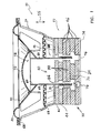
- FIG. 1 there is shown one example of a loudspeaker 20 including a motor assembly 22, a frame 24 mounted to motor assembly 22, a diaphragm 26, a lower suspension or spider 28 and an upper suspension or surround 30.
- Motor assembly 22 includes a pole piece 40 having a stack of four steel discs 32, a permanent magnet 36 below the bottom one of discs 32, and another steel disc 34 disposed below magnet 36. Each of discs 32, magnet 36 and disc 34 may be adhered to each other.
- Motor assembly 22 also includes a cylindrical structure 38 surrounding pole piece 40 and having a steel annular top ring 42 disposed atop an annular ring magnet 44. Magnet 44 in turn, is disposed atop a stack of another four steel annular rings 46. Each of top ring 42, magnetic ring 44, and rings 46 may be adhered to each other. Discs 32, 34 and rings 42, 46 may all be made of low carbon steel.
- An air gap 54 is defined between cylinder 38 and pole piece 40.
- the two opposite ends of air gap 54 are both open to air flow therethrough and are separated from each other in an axial direction indicated by double arrow 55.
- a voice coil 56 is also provided which includes a hollow, cylindrical-shaped former 58, having an inner surface 60 and an outer surface 62 which receives a wire winding 64.
- former 58 is concentrically disposed about pole piece 40, and voice coil 56 is axially movable within air gap 54 during operation of speaker 20.
- Voice coil 56 is held in place with respect to pole piece 40 by diaphragm 26, spider 28 and surround 30.
- One end of diaphragm 26 is affixed to former 58 by adhesive or the like, and the opposite end of diaphragm 26 connects to surround 30.
- Surround 30, in turn, is mounted to an upper end 66 of frame 24.
- Diaphragm 26 and surround 30 collectively provide support for voice coil 56, in addition to the lower suspension or spider 28.
- An inner annular edge of spider 28 connects to former 58, and an outer annular edge of spider 28 mounts to a seat 68 formed in frame 24.
- a dust cap 70 is mounted to the diaphragm 26 in position to overlie the voice coil 56 and pole piece 40 in order to protect such elements from dirt, dust and other contaminants.
- a dust cap cavity 72 is thus defined in the space surrounded by the lower portion of diaphragm 26, dust cap 70, voice coil 56 and pole piece 40.
- voice coil 56 is moved axially with respect to the fixed motor assembly 22.
- diaphragm 26, spider 28, surround 30 and dust cap 70 are operatively connected to former 58, these components also move axially along with voice coil 56.
- Pole piece 40 has an exterior surface that is both stepped and annular.
- the top one of steel discs 32 has a larger diameter than the disc 32 immediately below.
- Magnet 36 has a smaller diameter than any of discs 32, 34.
- Ring magnet 44 is disposed opposite the smallest of discs 32, and has an inner diameter that is larger than that of top steel ring 42 and three of steel rings 46.
- the steel ring 46 opposite magnet 36 has a larger inner diameter than any other element in cylinder 38, including ring magnet 44.
- a steel circular base plate 74 is adhered to both a bottom surface of cylinder 38 and a bottom surface of pole piece 40, and thereby interconnects cylinder 38 and pole piece 40.
- Base plate 74 includes a plurality of circumferentially evenly spaced throughbores 76 that fluidly interconnect air gap 54 with ambient air.
- a gap 86 is defined between a top one of discs 32 and former 58 of voice coil 56.
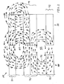
- magnets 36 and 44 may have a same magnetic polarity. Specifically, in the embodiment of FIG. 2 , each of magnets 36 and 44 has a north pole facing upward and a south pole facing downward. Because magnets 36 and 44 are on opposite sides of air gap 54, this same polarity results in magnets 36 and 44 contributing in a same direction to the flux in a middle magnetic gap 78. That is, magnets 36 and 44 both provide a magnetic flux in a radially outward direction (left to right direction in FIG. 2 ) in a portion of middle magnetic gap 78 that coincides with air gap 54, which is where voice coil 56 operates.
- Voice coil 56 is at least partially disposed in air gap 54 and operates primarily in middle magnetic gap 78. Because voice coil 56 operates in the portion of air gap 54 within middle magnetic gap 78, voice coil 56 relies on the magnetic flux within middle magnetic gap 78 to exert a magnetic force on voice coil 56 and thereby cause voice coil 56 to move while electrical current is flowing through voice coil 56. Thus, it is advantageous to have a larger flux created with the contributions of both magnets 36 and 44 rather than a smaller net flux which would result from the flux of one magnet partially cancelling out the flux of the other magnet, as would be the case if magnets 36 and 44 had opposite polarities.
- a top magnetic gap 80 is disposed axially adjacent top magnet 44 and opposite middle magnetic gap 78.
- a bottom magnetic gap 82 is disposed axially adjacent bottom magnet 36 and opposite middle magnetic gap 78.
- a direction of magnetic flux in top magnetic gap 80 and in bottom magnetic gap 82 may be opposite to the direction of flux within middle magnetic gap 78. More particularly, the flux in middle magnetic gap 78 is in a radially outward direction (left to right in FIG. 2 ) within air gap 54, but the flux is in a radially inward direction (right to left in FIG. 2 ) in both top magnetic gap 80 and bottom magnetic gap 82 within air gap 54.
- the direction of force exerted on voice coil 56 in top magnetic gap 80 and in bottom magnetic gap 82 may be opposite to the direction of force exerted on voice coil 56 in middle magnetic gap 78. Consequently, the flux in top magnetic gap 80 and in bottom magnetic gap 82 may limit the movement of voice coil 56 as caused by the flux in middle magnetic gap 78. Although whether the flux in middle magnetic gap 78 pushes voice coil 56 in an upward direction or a downward direction may depend upon the direction of current flow within voice coil 56, the flux in each of top magnetic gap 80 and in bottom magnetic gap 82 may push voice coil 56 in the opposite direction, thereby limiting the range of vertical movement of voice coil 56.
- middle magnetic gap 78 pushes voice coil 56 in a downward direction toward bottom magnetic gap 82, as voice coil 56 approaches bottom magnetic gap 82, voice coil 56 is increasingly influenced by the flux in bottom magnetic gap 82 and decreasingly influenced by the flux in middle magnetic gap 78. If the flux in middle magnetic gap 78 pushes voice coil 56 downward, then the flux in bottom magnetic gap 82 pushes voice coil 56 upward.
- the upwardly directed force exerted by the flux in bottom magnetic gap 82 operates to slow down voice coil 56 to a dead stop at some vertical level, and then possibly reverses the direction of movement of voice coil 56 (i.e., moves voice coil 56 in an upward direction).
- lower magnet 36 which is the source of the magnetic flux in bottom magnetic gap 82, may limit the downward axial movement of voice coil 56 within air gap 54.
- top magnetic gap 80 pushes voice coil 56 downward.
- the downwardly directed force exerted by the flux in top magnetic gap 80 operates to slow down voice coil 56 to a dead stop at some vertical level, and then possibly reverses the direction of movement of voice coil 56 (i.e., moves voice coil 56 in a downward direction).
- upper magnet 44 which is the source of the magnetic flux in top magnetic gap 80, may limit the upward axial movement of voice coil 56 within air gap 54.
- Top and bottom magnetic gaps 80, 82 may function as magnetic breaks and more symmetrically limit the vertical excursion of coil 56.
- magnets 36, 44 have a same polarity, magnets 36, 44 do not have to be magnetized in isolation from each other. Thus, by virtue of magnets 36, 44 having a same magnetic polarity, magnets 36, 44 may be magnetized after speaker 20 has been assembled. Assembling speaker 20 before magnets 36, 44 have been magnetized may be easier than assembling speaker 20 after magnets 36, 44 have been magnetized because magnetized magnets may exert forces on other speaker parts, thereby making assembly difficult.
- Another advantage of the structure of speaker 20 is that air may flow freely between cavity 72 and ambient air. More particularly, air may flow from the ambient environment, through each of throughbore 76, air gap 54 and gap 86, and into cavity 72. The air may exit out of cavity 72 to the ambient environment through the same path.
- one or more of discs 32, 34 may have laterally-oriented air passageways (not shown) and axial recesses (not shown) for fluidly interconnecting air gap 54 with cavity 72 and/or the ambient environment through a central throughbore (not shown) in plate 74.
- one or more of rings 42, 46 may have laterally-oriented air passageways (not shown) for fluidly interconnecting air gap 54 with ambient air.
- the above-described air passageways may facilitate a pumped flow of air past voice coil 56 to thereby have a cooling effect on voice coil 56, which may improve the performance of voice coil 56.
- cooling coil 56 may avoid demagnetization of magnets 36, 44 if the magnets are made of neomidium. Placing neomidium magnetic material too close to heat may tend to demagnetize the neomidium.
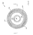
- FIGS. 3 and 4 Illustrated in FIGS. 3 and 4 is a bottom view and cross-sectional view, respectively, of another example of a motor assembly 122 that may be used within a loudspeaker.
- Motor assembly 122 includes an "inner" magnet configuration that accommodates applications in which a magnet on the outer cylindrical wall is not desirable.
- Motor assembly 122 includes a pole piece 140 having a central throughbore 184; a top steel ring 132; a permanent ring magnet 136 disposed below ring 132; a stacked pair of steel rings 134 disposed below magnet 136; another permanent ring magnet 144 disposed below rings 134; and another steel ring 142 disposed below ring magnet 144.
- the entire stack including steel ring 132, magnet 136, steel rings 134, magnet 144 and steel ring 142 may be adhered together.
- Motor assembly 122 also includes a steel cylindrical structure or tube 138 surrounding pole piece 140. Cylindrical structure 138 may provide a magnetic return path for magnets 136, 144 to thereby complete the magnetic circuit.
- An air gap 154 is defined between cylinder 138 and pole piece 140.
- the two opposite ends of air gap 154 are both open to air flow therethrough and are separated from each other in an axial direction indicated by double arrow 155.
- Pole piece 140 has an exterior surface that is both stepped and annular.
- steel ring 132 has a larger outer diameter than magnet 136.
- Magnet 136 has a smaller outer diameter than the two discs 134 immediately below, which have equal outer diameters.
- Magnet 144 has an outer diameter that is equal to that of magnet 136.
- Steel ring 142 has an outer diameter that is equal to the outer diameter of steel ring 132.
- a steel circular base plate 174 is adhered to both a bottom surface of cylinder 138 and a bottom surface of pole piece 140, and thereby interconnects cylinder 138 and pole piece 140.
- Base plate 174 includes a plurality of circumferentially evenly spaced throughbores 176 that fluidly interconnect air gap 154 with ambient air.
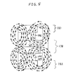
- magnets 136 and 144 may have an opposite magnetic polarity. Specifically, in the embodiment of FIG. 5 , magnet 144 has a north pole facing upward and magnet 136 has a north pole facing downward. Because magnets 136 and 144 are on the same side of air gap 154, this opposite polarity results in magnets 136 and 144 contributing in a same direction to the flux in a middle magnetic gap 178. That is, magnets 136 and 144 both provide a magnetic flux in a radially outward direction (left to right direction in FIG. 5 ) in a portion of middle magnetic gap 178 that coincides with air gap 154, which is where the voice coil operates.
- a top magnetic gap 180 is disposed axially adjacent top magnet 136 and opposite middle magnetic gap 178.
- a bottom magnetic gap 182 is disposed axially adjacent bottom magnet 144 and opposite middle magnetic gap 178.
- a direction of magnetic flux in top magnetic gap 180 and in bottom magnetic gap 182 may be opposite to the direction of flux within middle magnetic gap 178. More particularly, the flux in middle magnetic gap 178 is in a radially outward direction (left to right in FIG. 5 ) within air gap 154, but the flux is in a radially inward direction (right to left in FIG. 5 ) in both top magnetic gap 180 and bottom magnetic gap 182 within air gap 154.
- the direction of force exerted on the voice coil in top magnetic gap 180 and in bottom magnetic gap 182 may be opposite to the direction of force exerted on the voice coil in middle magnetic gap 178. Consequently, the flux in top magnetic gap 180 and in bottom magnetic gap 182 may limit the movement of the voice coil as caused by the flux in middle magnetic gap 178. Although whether the flux in middle magnetic gap 178 pushes the voice coil in an upward direction or a downward direction may depend upon the direction of current flow within the voice coil, the flux in each of top magnetic gap 180 and in bottom magnetic gap 182 may push the voice coil in the opposite direction, thereby limiting the range of vertical movement of the voice coil.
- middle magnetic gap 178 pushes the voice coil in a downward direction toward bottom magnetic gap 182
- the voice coil is increasingly influenced by the flux in bottom magnetic gap 182 and decreasingly influenced by the flux in middle magnetic gap 178. If the flux in middle magnetic gap 178 pushes the voice coil downward, then the flux in bottom magnetic gap 182 pushes the voice coil upward.
- lower magnet 144 which is the source of the magnetic flux in bottom magnetic gap 182, may limit the downward axial movement of the voice coil within air gap 154.
- top magnetic gap 180 pushes the voice coil downward.
- the downwardly directed force exerted by the flux in top magnetic gap 180 operates to slow down the voice coil to a dead stop at some vertical level, and then possibly reverses the direction of movement of the voice coil (i.e., moves the voice coil in a downward direction).
- upper magnet 136 which is the source of the magnetic flux in top magnetic gap 180, may limit the upward axial movement of the voice coil within air gap 154.
- Top and bottom magnetic gaps 180, 182 may function as magnetic breaks and more symmetrically limit the vertical excursion of the voice coil.
- Loudspeaker 200 Illustrated in FIG. 6 is shown an example of a loudspeaker 200 in which both of the magnets are on the outer cylinder.
- Loudspeaker 200 includes a motor assembly 222 having a pole piece 240 with a stack of six steel discs 232. Each of discs 232 may be adhered to each other.
- Motor assembly 222 also includes a cylindrical structure 238 surrounding pole piece 240 and having a steel annular top ring 242 disposed atop an annular ring magnet 244. Magnet 244 in turn, is disposed atop a stack of another two steel annular rings 246. Immediately below steel rings 246 is another annular ring magnet 236. Magnet 236 is disposed atop another steel annular ring 247.
- top ring 242, magnetic ring 244, middle rings 246, magnetic ring 236, and bottom ring 247 may be adhered to each other.
- Discs 232 and rings 242, 246 and 247 may all be made of low carbon steel.
- Pole piece 240 has an exterior surface that is both stepped and annular.
- the top one, the middle two, and the bottom one of steel discs 232 have an equal diameter that is larger than the diameter of the second disc 232 from the top.
- the second disc 232 from the bottom has the smallest diameter among discs 232.
- steel rings 242, 246 and 247 have an equal inner diameter that is smaller than the inner diameter of ring magnet 244.
- Ring magnet 247 has the largest inner diameter among all of the elements within cylinder 238.
- Other aspects of the structure of loudspeaker 200 may be substantially similar to that of loudspeaker 20, and thus are not described herein in order to avoid needless repetition.
- magnets 236 and 244 may have opposite magnetic polarities. Specifically, in the example of FIG. 7 , magnet 244 has a north pole facing upward and magnet 236 has a north pole facing downward. Because magnets 236 and 244 are on the same side of air gap 254, this opposite polarity results in magnets 236 and 244 contributing in a same direction to the flux in a middle magnetic gap 278. That is, magnets 236 and 244 both provide a magnetic flux in a radially outward direction (left to right direction in FIG. 7 ) in a portion of middle magnetic gap 278 that coincides with air gap 254, which is where voice coil 56 operates.
- Voice coil 56 is at least partially disposed in air gap 254 and operates primarily in middle magnetic gap 278. Because voice coil 56 operates in the portion of air gap 254 within middle magnetic gap 278, voice coil 56 relies on the magnetic flux within middle magnetic gap 278 to exert a magnetic force on voice coil 56 and thereby cause voice coil 56 to move while electrical current is flowing through voice coil 56. Thus, it is advantageous to have a larger flux created with the contributions of both magnets 236 and 244 rather than a smaller net flux which would result from the flux of one magnet partially cancelling out the flux of the other magnet, as would be the case if magnets 236 and 244 had opposite polarities.
- a top magnetic gap 280 is disposed axially adjacent top magnet 244 and opposite middle magnetic gap 278.
- a bottom magnetic gap 282 is disposed axially adjacent bottom magnet 236 and opposite middle magnetic gap 278.
- a direction of magnetic flux in top magnetic gap 280 and in bottom magnetic gap 282 may be opposite to the direction of flux within middle magnetic gap 278. More particularly, the flux in middle magnetic gap 278 is in a radially outward direction (left to right in FIG. 7 ) within air gap 254, but the flux is in a radially inward direction (right to left in FIG. 7 ) in both top magnetic gap 280 and bottom magnetic gap 282 within air gap 254.
- the direction of force exerted on voice coil 56 in top magnetic gap 280 and in bottom magnetic gap 282 may be opposite to the direction of force exerted on voice coil 56 in middle magnetic gap 278. Consequently, the flux in top magnetic gap 280 and in bottom magnetic gap 282 may limit the movement of voice coil 56 as caused by the flux in middle magnetic gap 278. Although whether the flux in middle magnetic gap 278 pushes voice coil 56 in an upward direction or a downward direction may depend upon the direction of current flow within voice coil 56, the flux in each of top magnetic gap 280 and in bottom magnetic gap 282 may push voice coil 56 in the opposite direction, thereby limiting the range of vertical movement of voice coil 56.
- top magnetic gap 280 pushes voice coil 56 downward.
- the downwardly directed force exerted by the flux in top magnetic gap 280 operates to slow down voice coil 56 to a dead stop at some vertical level, and then possibly reverses the direction of movement of voice coil 56 (i.e., moves voice coil 56 in a downward direction).
- upper magnet 244 which is the source of the magnetic flux in top magnetic gap 280, may limit the upward axial movement of voice coil 56 within air gap 254.
- Top and bottom magnetic gaps 280, 282 may function as magnetic breaks and more symmetrically limit the vertical excursion of coil 56.
- Another advantage of the structure of speaker 200 is that air may flow freely between cavity 72 and ambient air. More particularly, air may flow from the ambient environment, through each of throughbore 76, air gap 254 and gap 86, and into cavity 72. The air may exit out of cavity 72 to the ambient environment through the same path.
- one or more of discs 232 may have laterally-oriented air passageways (not shown) and axial recesses (not shown) for fluidly interconnecting air gap 254 with cavity 72 and/or the ambient environment through a central throughbore (not shown) in plate 74.
- one or more of rings 242, 246, 247 may have laterally-oriented air passageways (not shown) for fluidly interconnecting air gap 254 with ambient air. The above-described air passageways may facilitate a pumped flow of air past voice coil 56 to thereby have a cooling effect on voice coil 56, which may improve the performance of voice coil 56.
- FIG. 8 Illustrated in FIG. 8 is a cross-sectional view of another example of a motor assembly 272 including a pole 293, an annular magnet 286, a disc-shaped magnet 287, a plurality of annular steel rings 282a-d, and steel discs 284a-b. Magnets 286, 287 may have the same polarity.
- Pole 293 includes a throughbore or upwardly facing recess 290.
- Pole 293 includes a larger diameter upper section 274 and a smaller diameter lower section 276.
- a plurality of circumferentially spaced air passages 288 extend from the lower portion of throughbore 290 to the outer surface of lower section 276. Air passages 288 may be rectangular in cross section.
- Air flow may be driven by the force exerted on air trapped inside a dust cap, such as dust cap 70, and the inner circumferential surface of a voice coil, such as voice coil 56.
- the air flows in a generally lateral direction through air passages 288 in pole 293, and then flows downward through a cylindrical air gap 294.
- the air may flow in a direction opposite to that shown, depending on the current direction of movement of the spider.
- pole piece 293 includes a plurality of laterally-oriented air passageways 288 at a substantially same vertical level as that of magnet 286. Air passageways 288 are in fluid communication with the upwardly facing recess 290.
- FIG. 9 Illustrated in FIG. 9 is a cross-sectional view of yet another example of a motor assembly 322 including a pole 340 having a top pole half 342 and a bottom pole half 344.
- Motor assembly 322 also includes a top annular magnet 336, a bottom annular magnet 337, a plurality of annular steel rings 332a-c, and a donut-shaped back plate 334.
- Magnets 336, 337 may have opposite polarities such that magnets 336, 337 provide flux in a same direction through steel ring 332b.
- magnet 336 may have its north pole on its top surface, while magnet 337 has its north pole on its bottom surface.
- magnet 336 may have its north pole on its bottom surface, while magnet 337 has its north pole on its top surface.
- Top pole half 342 may have a structure that is similar to that of pole 293.
- Bottom pole half 344 includes a bore 348 that is in communication with a bottom surface 350 of bottom half 44, and that extends only partially through the height of bottom half 344. Bore 348 is aligned and in communication with a throughbore 352 extending through back plate 334. Throughbore 352 terminates with a port 353 which is open to atmosphere at back plate 334. Bottom half 344 includes a larger diameter upper section 378 and a smaller diameter lower section 380. A plurality of circumferentially spaced air passages 384 extend from bore 348 to the outer surface of lower section 380. Air passages 384 may be rectangular in cross section. Back plate 334 may have an annular outer surface 338 facing a cylindrical air gap 354.
- Air flow may be driven by the force exerted on air trapped inside a dust cap, such as dust cap 70, and the inner circumferential surface of a voice coil, such as voice coil 56.
- the air flows in a generally lateral direction through air passages 382 in top pole half 342, and then flows downward through air gap 354.
- the air then flows in an opposite generally lateral direction through air passages 384 in bottom pole half 344, through throughbore 352 in back plate 334, and out through port 353.
- the overall path of air flow may be spiraling. That is, the air flow path may be three-dimensional, having components in a clockwise or counterclockwise direction around pole piece 340. The air may flow in a direction opposite to that shown, depending on the current direction of movement of the spider and/or the former.
- pole piece 340 includes a plurality of laterally-oriented air passageways 382 in fluid communication with an upwardly facing recess 390 and disposed at a substantially same vertical level as magnet 336.
- Pole piece 340 also includes a plurality of laterally-oriented air passageways 384 at a substantially same vertical level as magnet 337 and in fluid communication with a downwardly facing recess in the form of throughbore 352.
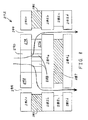
- FIG. 10 Illustrated in FIG. 10 is a cross-sectional view of an embodiment of a motor assembly 422 of the present invention including a pole 443, an annular magnet 436, a disc-shaped magnet 437, a plurality of annular steel rings 432a-d, and steel discs 434a-b. Magnets 436, 437 may have the same polarity. Pole 443 may have a structure that is similar to that of pole 293.
- Air flow may be driven by the force exerted on air trapped inside a dust cap, such as dust cap 70, and the inner circumferential surface of a voice coil, such as voice coil 56.
- the air flows in a generally lateral direction through air passages 482 in pole 443, and then flows downward within a cylindrical air gap 454.
- the air flow may then exit air gap 454 through laterally-oriented air passageways 433 in steel ring 432c.
- pole piece 443 includes a plurality of laterally-oriented air passageways 482 in fluid communication with an upwardly facing recess 490 and disposed at a substantially same vertical level as magnet 436.
- Cylindrical structure 438 includes a plurality of laterally-oriented air passageways 433 at a substantially same vertical level as magnet 437.
- annular non-ferrous (e.g., aluminum) rings 459, 461 the edges of which are indicated by dashed lines in FIG. 10 , may be adhered to magnets 436, 437, respectively, in order to further smooth out the air flow path within air gap 454
- Each of the embodiments shown herein includes at least one magnet that is recessed in an outer surface of the pole piece and/or recessed in an inner surface of the cylindrical structure. As best shown in FIGS. 2 and 7 , the recessed position of the magnet enables the flux from each of the two magnets to be directed in a substantially same lateral direction within the air gap.
- a non-ferrous ring may be disposed in any number of these recesses between the air gap and one of the magnets such that the ring provides the air gap with a smooth boundary. Such a smooth boundary may decrease the resistance to air flow within the air gap, and may thereby increase the speed and volume of air flow through the air gap. Accordingly, the cooling effect on the voice coil as a result of the air flow may be improved.
- the embodiments disclosed herein include low reluctance magnetic return paths for the magnets. That is, the flux travels through low reluctance steel in some portion of its path from a north pole to a south pole.
- the magnetic return paths it is within the scope of the invention for the magnetic return paths to be high reluctance, without any steel within the magnetic return path. That is, the magnetic return path may travel entirely through high reluctance air.
- the magnets may be made stronger with a higher degree of magnetism.
Landscapes
- Engineering & Computer Science (AREA)
- Physics & Mathematics (AREA)
- Acoustics & Sound (AREA)
- Signal Processing (AREA)
- Power Engineering (AREA)
- Audible-Bandwidth Dynamoelectric Transducers Other Than Pickups (AREA)
Description
- The present invention relates to a low frequency transducer arrangement according to the preamble of
claim 1 which is known fromJP 57 009 197 A -
US 624 379 B1 discloses a low frequency transducer arrangement including an air gap between a pole piece and a substantially cylindrical structure, wherein the two opposite ends of the air gap both are open to airflow therethrough and are separated from each other in an axial direction. -
JP 2007 104 626 A - A high power low frequency transducer, commonly referred to as a "loudspeaker," has a magnetic structure with "air gaps" and voice coils that are located in the air gap(s). At normal operating sound pressure levels, it is common for the voice coil temperature to reach 280 °C (536 °F). This high temperature has the deleterious effect of reducing the transducer's efficiency and reliability. Known techniques for reducing the voice coil temperature include using air circulation to cool the voice coil, but these known techniques have not provided sufficient air flow in terms of volume and velocity in order to be effective.
- Another problem with known high power loudspeakers is that the extreme force involved in oscillating the voice coil in axial directions sometimes results in physical damage to the loudspeaker. For example, the inertia of the moving voice coil may cause the voice coil to oscillate beyond a safe range of movement, thereby resulting in collisions between speaker components, or pulling speaker components apart from one another.
- What is neither disclosed nor suggested by the prior art is a high power low frequency transducer in which the operating temperature of the voice coil is effectively limited to thereby preserve the voice coil's efficiency and reliability, and in which the range of movement of the voice coil is effectively limited to thereby prevent damage to the transducer.
- The present invention is directed to a high power low frequency transducer having a magnetic structure with an air gap and a voice coil located in the air gap. In one embodiment, two magnets are magnetized in opposite polarities. These magnets are located on opposite sides of a steel disk and on the same, inner side of the air gap. Both ends of the air gap are open to atmosphere. Two more steel disks are disposed above the upper magnet and below the lower magnet, respectively. A steel tube surrounds the structure to define the outer boundary of the air gap and thereby form a top magnetic gap above the magnets, a center magnetic gap between the magnets, and a bottom magnetic gap below the magnets.
- Aluminum rings may be adhered to the exposed ends of the magnets such that the rings are flush with the steel disks, thereby providing the air gap with a smooth boundary for improved air flow. The flux from the two magnets may be in the same direction in the middle magnetic gap, where the coil operates. The flux in the top and bottom magnetic gaps may be opposite to the flux in the middle magnetic gap, thereby inhibiting the coil from traveling beyond desired limits. In a second embodiment, the magnets have the same polarity and are disposed on opposite sides of the air gap. Other aspects may be similar to the first embodiment.
- In one embodiment, one magnet is disposed on the inside of the air gap and another magnet is disposed on the outside of the air gap. With this configuration, the two magnets may have the same polarity. Advantageously, if the magnets have the same polarity, the loudspeaker may be assembled prior to the magnets being magnetized.
- The invention provides a low frequency transducer arrangement as defined in
independent claim 1. - Preferred embodiments are listed in the dependent claims.
- An advantage of the present invention is that it provides a straight line air path from top to bottom to allow forced air cooling to remove heat from the voice coil.
- Another advantage of the present invention is that it enables the top and bottom magnetic gaps to be used for magnetic limiting.
- The above mentioned and other features and objects of this invention, and the manner of attaining them, will become more apparent and the invention itself will be better understood by reference to the following description of embodiments of the invention taken in conjunction with the accompanying drawings, wherein:
-
FIG. 1 is a cross-sectional view of an example of a loudspeaker. -
FIG. 2 is a schematic view of a B field plot of the motor assembly of the loudspeaker ofFIG. 1 . -
FIG. 3 is a bottom view of another example of a motor assembly that may be used in a loudspeaker. -
FIG. 4 is a cross-sectional view of another example of a loudspeaker including the motor assembly ofFIG. 3 along theline 4--4. -
FIG. 5 is a schematic view of a B field plot of the motor assembly ofFIG. 4 . -
FIG. 6 is a cross-sectional view of yet another example of a loudspeaker. -
FIG. 7 is a schematic view of a B field plot of the motor assembly of the loudspeaker ofFIG. 6 . -
FIG. 8 is a cross-sectional view of another example of a motor assembly. -
FIG. 9 is a cross-sectional view of yet another example of a motor assembly. -
FIG. 10 is a cross-sectional view of an embodiment of a motor assembly of the present invention. - Corresponding reference characters indicate corresponding parts throughout the several views. Although the exemplification set out herein illustrates embodiments of the invention, in several forms, the embodiments disclosed below are not intended to be exhaustive or to be construed as limiting the scope of the invention to the precise forms disclosed.
- Referring now to the drawings, and particularly to
FIG. 1 , there is shown one example of aloudspeaker 20 including amotor assembly 22, aframe 24 mounted tomotor assembly 22, adiaphragm 26, a lower suspension orspider 28 and an upper suspension or surround 30.Motor assembly 22 includes apole piece 40 having a stack of foursteel discs 32, apermanent magnet 36 below the bottom one ofdiscs 32, and anothersteel disc 34 disposed belowmagnet 36. Each ofdiscs 32,magnet 36 anddisc 34 may be adhered to each other. -
Motor assembly 22 also includes acylindrical structure 38 surroundingpole piece 40 and having a steelannular top ring 42 disposed atop anannular ring magnet 44.Magnet 44 in turn, is disposed atop a stack of another four steelannular rings 46. Each oftop ring 42,magnetic ring 44, andrings 46 may be adhered to each other.Discs rings - An
air gap 54 is defined betweencylinder 38 andpole piece 40. The two opposite ends ofair gap 54 are both open to air flow therethrough and are separated from each other in an axial direction indicated bydouble arrow 55. - A voice coil 56 is also provided which includes a hollow, cylindrical-shaped former 58, having an
inner surface 60 and anouter surface 62 which receives a wire winding 64. Former 58 is concentrically disposed aboutpole piece 40, and voice coil 56 is axially movable withinair gap 54 during operation ofspeaker 20. - Voice coil 56 is held in place with respect to
pole piece 40 bydiaphragm 26,spider 28 andsurround 30. One end ofdiaphragm 26 is affixed to former 58 by adhesive or the like, and the opposite end ofdiaphragm 26 connects tosurround 30. Surround 30, in turn, is mounted to anupper end 66 offrame 24.Diaphragm 26 and surround 30 collectively provide support for voice coil 56, in addition to the lower suspension orspider 28. An inner annular edge ofspider 28 connects to former 58, and an outer annular edge ofspider 28 mounts to aseat 68 formed inframe 24. - A
dust cap 70 is mounted to thediaphragm 26 in position to overlie the voice coil 56 andpole piece 40 in order to protect such elements from dirt, dust and other contaminants. Adust cap cavity 72 is thus defined in the space surrounded by the lower portion ofdiaphragm 26,dust cap 70, voice coil 56 andpole piece 40. In response to the input of electrical energy to wire winding 64, voice coil 56 is moved axially with respect to thefixed motor assembly 22. Becausediaphragm 26,spider 28,surround 30 anddust cap 70 are operatively connected to former 58, these components also move axially along with voice coil 56. As a result of axial movement ofdiaphragm 26 anddust cap 70, air flows from outside ofspeaker 20 and into and out ofcavity 72. That is, air is pumped into and out ofcavity 72. -
Pole piece 40 has an exterior surface that is both stepped and annular. In the specific embodiment shown inFIG. 1 , the top one ofsteel discs 32 has a larger diameter than thedisc 32 immediately below.Magnet 36 has a smaller diameter than any ofdiscs Ring magnet 44 is disposed opposite the smallest ofdiscs 32, and has an inner diameter that is larger than that oftop steel ring 42 and three of steel rings 46. However, thesteel ring 46opposite magnet 36 has a larger inner diameter than any other element incylinder 38, includingring magnet 44. - A steel
circular base plate 74 is adhered to both a bottom surface ofcylinder 38 and a bottom surface ofpole piece 40, and thereby interconnectscylinder 38 andpole piece 40.Base plate 74 includes a plurality of circumferentially evenly spaced throughbores 76 that fluidly interconnectair gap 54 with ambient air. Agap 86 is defined between a top one ofdiscs 32 and former 58 of voice coil 56. - As shown in
FIG. 2 ,magnets FIG. 2 , each ofmagnets magnets air gap 54, this same polarity results inmagnets magnetic gap 78. That is,magnets FIG. 2 ) in a portion of middlemagnetic gap 78 that coincides withair gap 54, which is where voice coil 56 operates. - Voice coil 56 is at least partially disposed in
air gap 54 and operates primarily in middlemagnetic gap 78. Because voice coil 56 operates in the portion ofair gap 54 within middlemagnetic gap 78, voice coil 56 relies on the magnetic flux within middlemagnetic gap 78 to exert a magnetic force on voice coil 56 and thereby cause voice coil 56 to move while electrical current is flowing through voice coil 56. Thus, it is advantageous to have a larger flux created with the contributions of bothmagnets magnets - As also may be seen in
FIG. 2 , a topmagnetic gap 80 is disposed axially adjacenttop magnet 44 and opposite middlemagnetic gap 78. A bottommagnetic gap 82 is disposed axiallyadjacent bottom magnet 36 and opposite middlemagnetic gap 78. A direction of magnetic flux in topmagnetic gap 80 and in bottommagnetic gap 82 may be opposite to the direction of flux within middlemagnetic gap 78. More particularly, the flux in middlemagnetic gap 78 is in a radially outward direction (left to right inFIG. 2 ) withinair gap 54, but the flux is in a radially inward direction (right to left inFIG. 2 ) in both topmagnetic gap 80 and bottommagnetic gap 82 withinair gap 54. Thus, the direction of force exerted on voice coil 56 in topmagnetic gap 80 and in bottommagnetic gap 82 may be opposite to the direction of force exerted on voice coil 56 in middlemagnetic gap 78. Consequently, the flux in topmagnetic gap 80 and in bottommagnetic gap 82 may limit the movement of voice coil 56 as caused by the flux in middlemagnetic gap 78. Although whether the flux in middlemagnetic gap 78 pushes voice coil 56 in an upward direction or a downward direction may depend upon the direction of current flow within voice coil 56, the flux in each of topmagnetic gap 80 and in bottommagnetic gap 82 may push voice coil 56 in the opposite direction, thereby limiting the range of vertical movement of voice coil 56. For example, if the flux in middlemagnetic gap 78 pushes voice coil 56 in a downward direction toward bottommagnetic gap 82, as voice coil 56 approaches bottommagnetic gap 82, voice coil 56 is increasingly influenced by the flux in bottommagnetic gap 82 and decreasingly influenced by the flux in middlemagnetic gap 78. If the flux in middlemagnetic gap 78 pushes voice coil 56 downward, then the flux in bottommagnetic gap 82 pushes voice coil 56 upward. Depending upon the degree of downward momentum possessed by voice coil 56 as provided by the flux in middlemagnetic gap 78, the upwardly directed force exerted by the flux in bottommagnetic gap 82 operates to slow down voice coil 56 to a dead stop at some vertical level, and then possibly reverses the direction of movement of voice coil 56 (i.e., moves voice coil 56 in an upward direction). Thus, as described above,lower magnet 36, which is the source of the magnetic flux in bottommagnetic gap 82, may limit the downward axial movement of voice coil 56 withinair gap 54. - Conversely, if the flux in middle
magnetic gap 78 pushes voice coil 56 upward, then the flux in topmagnetic gap 80 pushes voice coil 56 downward. Depending upon the degree of upward momentum possessed by voice coil 56 as provided by the flux in middlemagnetic gap 78, the downwardly directed force exerted by the flux in topmagnetic gap 80 operates to slow down voice coil 56 to a dead stop at some vertical level, and then possibly reverses the direction of movement of voice coil 56 (i.e., moves voice coil 56 in a downward direction). Thus, as described above,upper magnet 44, which is the source of the magnetic flux in topmagnetic gap 80, may limit the upward axial movement of voice coil 56 withinair gap 54. Top and bottommagnetic gaps - Because
magnets magnets magnets magnets speaker 20 has been assembled. Assemblingspeaker 20 beforemagnets speaker 20 aftermagnets - Another advantage of the structure of
speaker 20 is that air may flow freely betweencavity 72 and ambient air. More particularly, air may flow from the ambient environment, through each ofthroughbore 76,air gap 54 andgap 86, and intocavity 72. The air may exit out ofcavity 72 to the ambient environment through the same path. Moreover, one or more ofdiscs air gap 54 withcavity 72 and/or the ambient environment through a central throughbore (not shown) inplate 74. In addition, one or more ofrings air gap 54 with ambient air. The above-described air passageways may facilitate a pumped flow of air past voice coil 56 to thereby have a cooling effect on voice coil 56, which may improve the performance of voice coil 56. Moreover, cooling coil 56 may avoid demagnetization ofmagnets - Illustrated in
FIGS. 3 and4 is a bottom view and cross-sectional view, respectively, of another example of amotor assembly 122 that may be used within a loudspeaker.Motor assembly 122 includes an "inner" magnet configuration that accommodates applications in which a magnet on the outer cylindrical wall is not desirable. -
Motor assembly 122 includes apole piece 140 having acentral throughbore 184; atop steel ring 132; apermanent ring magnet 136 disposed belowring 132; a stacked pair of steel rings 134 disposed belowmagnet 136; anotherpermanent ring magnet 144 disposed belowrings 134; and anothersteel ring 142 disposed belowring magnet 144. The entire stack includingsteel ring 132,magnet 136, steel rings 134,magnet 144 andsteel ring 142 may be adhered together. -
Motor assembly 122 also includes a steel cylindrical structure ortube 138 surroundingpole piece 140.Cylindrical structure 138 may provide a magnetic return path formagnets - An
air gap 154 is defined betweencylinder 138 andpole piece 140. The two opposite ends ofair gap 154 are both open to air flow therethrough and are separated from each other in an axial direction indicated bydouble arrow 155. -
Pole piece 140 has an exterior surface that is both stepped and annular. In the specific embodiment shown inFIG. 4 ,steel ring 132 has a larger outer diameter thanmagnet 136.Magnet 136 has a smaller outer diameter than the twodiscs 134 immediately below, which have equal outer diameters.Magnet 144 has an outer diameter that is equal to that ofmagnet 136.Steel ring 142 has an outer diameter that is equal to the outer diameter ofsteel ring 132. - A steel
circular base plate 174 is adhered to both a bottom surface ofcylinder 138 and a bottom surface ofpole piece 140, and thereby interconnectscylinder 138 andpole piece 140.Base plate 174 includes a plurality of circumferentially evenly spacedthroughbores 176 that fluidly interconnectair gap 154 with ambient air. - As shown in
FIG. 5 ,magnets FIG. 5 ,magnet 144 has a north pole facing upward andmagnet 136 has a north pole facing downward. Becausemagnets air gap 154, this opposite polarity results inmagnets magnetic gap 178. That is,magnets FIG. 5 ) in a portion of middlemagnetic gap 178 that coincides withair gap 154, which is where the voice coil operates. - As also may be seen in
FIG. 5 , a topmagnetic gap 180 is disposed axially adjacenttop magnet 136 and opposite middlemagnetic gap 178. A bottommagnetic gap 182 is disposed axiallyadjacent bottom magnet 144 and opposite middlemagnetic gap 178. A direction of magnetic flux in topmagnetic gap 180 and in bottommagnetic gap 182 may be opposite to the direction of flux within middlemagnetic gap 178. More particularly, the flux in middlemagnetic gap 178 is in a radially outward direction (left to right inFIG. 5 ) withinair gap 154, but the flux is in a radially inward direction (right to left inFIG. 5 ) in both topmagnetic gap 180 and bottommagnetic gap 182 withinair gap 154. Thus, the direction of force exerted on the voice coil in topmagnetic gap 180 and in bottommagnetic gap 182 may be opposite to the direction of force exerted on the voice coil in middlemagnetic gap 178. Consequently, the flux in topmagnetic gap 180 and in bottommagnetic gap 182 may limit the movement of the voice coil as caused by the flux in middlemagnetic gap 178. Although whether the flux in middlemagnetic gap 178 pushes the voice coil in an upward direction or a downward direction may depend upon the direction of current flow within the voice coil, the flux in each of topmagnetic gap 180 and in bottommagnetic gap 182 may push the voice coil in the opposite direction, thereby limiting the range of vertical movement of the voice coil. For example, if the flux in middlemagnetic gap 178 pushes the voice coil in a downward direction toward bottommagnetic gap 182, as the voice coil approaches bottommagnetic gap 182, the voice coil is increasingly influenced by the flux in bottommagnetic gap 182 and decreasingly influenced by the flux in middlemagnetic gap 178. If the flux in middlemagnetic gap 178 pushes the voice coil downward, then the flux in bottommagnetic gap 182 pushes the voice coil upward. Depending upon the degree of downward momentum possessed by the voice coil as provided by the flux in middlemagnetic gap 178, the upwardly directed force exerted by the flux in bottommagnetic gap 182 operates to slow down the voice coil to a dead stop at some vertical level, and then possibly reverses the direction of movement of the voice coil (i.e., moves the voice coil in an upward direction). Thus, as described above,lower magnet 144, which is the source of the magnetic flux in bottommagnetic gap 182, may limit the downward axial movement of the voice coil withinair gap 154. - Conversely, if the flux in middle
magnetic gap 178 pushes the voice coil upward, then the flux in topmagnetic gap 180 pushes the voice coil downward. Depending upon the degree of upward momentum possessed by the voice coil as provided by the flux in middlemagnetic gap 178, the downwardly directed force exerted by the flux in topmagnetic gap 180 operates to slow down the voice coil to a dead stop at some vertical level, and then possibly reverses the direction of movement of the voice coil (i.e., moves the voice coil in a downward direction). Thus, as described above,upper magnet 136, which is the source of the magnetic flux in topmagnetic gap 180, may limit the upward axial movement of the voice coil withinair gap 154. Top and bottommagnetic gaps - Illustrated in
FIG. 6 is shown an example of aloudspeaker 200 in which both of the magnets are on the outer cylinder.Loudspeaker 200 includes amotor assembly 222 having apole piece 240 with a stack of sixsteel discs 232. Each ofdiscs 232 may be adhered to each other. -
Motor assembly 222 also includes acylindrical structure 238 surroundingpole piece 240 and having a steel annulartop ring 242 disposed atop anannular ring magnet 244.Magnet 244 in turn, is disposed atop a stack of another two steel annular rings 246. Immediately below steel rings 246 is anotherannular ring magnet 236.Magnet 236 is disposed atop another steelannular ring 247. - Each of
top ring 242,magnetic ring 244,middle rings 246,magnetic ring 236, andbottom ring 247 may be adhered to each other.Discs 232 and rings 242, 246 and 247 may all be made of low carbon steel. -
Pole piece 240 has an exterior surface that is both stepped and annular. In the specific embodiment shown inFIG. 6 , the top one, the middle two, and the bottom one ofsteel discs 232 have an equal diameter that is larger than the diameter of thesecond disc 232 from the top. Thesecond disc 232 from the bottom has the smallest diameter amongdiscs 232. - Similarly, steel rings 242, 246 and 247 have an equal inner diameter that is smaller than the inner diameter of
ring magnet 244.Ring magnet 247 has the largest inner diameter among all of the elements withincylinder 238. Other aspects of the structure ofloudspeaker 200 may be substantially similar to that ofloudspeaker 20, and thus are not described herein in order to avoid needless repetition. - As shown in
FIG. 7 ,magnets FIG. 7 ,magnet 244 has a north pole facing upward andmagnet 236 has a north pole facing downward. Becausemagnets air gap 254, this opposite polarity results inmagnets magnetic gap 278. That is,magnets FIG. 7 ) in a portion of middlemagnetic gap 278 that coincides withair gap 254, which is where voice coil 56 operates. - Voice coil 56 is at least partially disposed in
air gap 254 and operates primarily in middlemagnetic gap 278. Because voice coil 56 operates in the portion ofair gap 254 within middlemagnetic gap 278, voice coil 56 relies on the magnetic flux within middlemagnetic gap 278 to exert a magnetic force on voice coil 56 and thereby cause voice coil 56 to move while electrical current is flowing through voice coil 56. Thus, it is advantageous to have a larger flux created with the contributions of bothmagnets magnets - As also may be seen in
FIG. 7 , a topmagnetic gap 280 is disposed axially adjacenttop magnet 244 and opposite middlemagnetic gap 278. A bottommagnetic gap 282 is disposed axiallyadjacent bottom magnet 236 and opposite middlemagnetic gap 278. A direction of magnetic flux in topmagnetic gap 280 and in bottommagnetic gap 282 may be opposite to the direction of flux within middlemagnetic gap 278. More particularly, the flux in middlemagnetic gap 278 is in a radially outward direction (left to right inFIG. 7 ) withinair gap 254, but the flux is in a radially inward direction (right to left inFIG. 7 ) in both topmagnetic gap 280 and bottommagnetic gap 282 withinair gap 254. Thus, the direction of force exerted on voice coil 56 in topmagnetic gap 280 and in bottommagnetic gap 282 may be opposite to the direction of force exerted on voice coil 56 in middlemagnetic gap 278. Consequently, the flux in topmagnetic gap 280 and in bottommagnetic gap 282 may limit the movement of voice coil 56 as caused by the flux in middlemagnetic gap 278. Although whether the flux in middlemagnetic gap 278 pushes voice coil 56 in an upward direction or a downward direction may depend upon the direction of current flow within voice coil 56, the flux in each of topmagnetic gap 280 and in bottommagnetic gap 282 may push voice coil 56 in the opposite direction, thereby limiting the range of vertical movement of voice coil 56. For example, if the flux in middlemagnetic gap 278 pushes voice coil 56 in a downward direction toward bottommagnetic gap 282, as voice coil 56 approaches bottommagnetic gap 282, voice coil 56 is increasingly influenced by the flux in bottommagnetic gap 282 and decreasingly influenced by the flux in middlemagnetic gap 278. If the flux in middlemagnetic gap 278 pushes voice coil 56 downward, then the flux in bottommagnetic gap 282 pushes voice coil 56 upward. Depending upon the degree of downward momentum possessed by voice coil 56 as provided by the flux in middlemagnetic gap 278, the upwardly directed force exerted by the flux in bottommagnetic gap 282 operates to slow down voice coil 56 to a dead stop at some vertical level, and then possibly reverses the direction of movement of voice coil 56 (i.e., moves voice coil 56 in an upward direction). Thus, as described above,lower magnet 236, which is the source of the magnetic flux in bottommagnetic gap 282, may limit the downward axial movement of voice coil 56 withinair gap 254. - Conversely, if the flux in middle
magnetic gap 278 pushes voice coil 56 upward, then the flux in topmagnetic gap 280 pushes voice coil 56 downward. Depending upon the degree of upward momentum possessed by voice coil 56 as provided by the flux in middlemagnetic gap 278, the downwardly directed force exerted by the flux in topmagnetic gap 280 operates to slow down voice coil 56 to a dead stop at some vertical level, and then possibly reverses the direction of movement of voice coil 56 (i.e., moves voice coil 56 in a downward direction). Thus, as described above,upper magnet 244, which is the source of the magnetic flux in topmagnetic gap 280, may limit the upward axial movement of voice coil 56 withinair gap 254. Top and bottommagnetic gaps - Another advantage of the structure of
speaker 200 is that air may flow freely betweencavity 72 and ambient air. More particularly, air may flow from the ambient environment, through each ofthroughbore 76,air gap 254 andgap 86, and intocavity 72. The air may exit out ofcavity 72 to the ambient environment through the same path. Moreover, one or more ofdiscs 232 may have laterally-oriented air passageways (not shown) and axial recesses (not shown) for fluidly interconnectingair gap 254 withcavity 72 and/or the ambient environment through a central throughbore (not shown) inplate 74. In addition, one or more ofrings air gap 254 with ambient air. The above-described air passageways may facilitate a pumped flow of air past voice coil 56 to thereby have a cooling effect on voice coil 56, which may improve the performance of voice coil 56. - Illustrated in
FIG. 8 is a cross-sectional view of another example of amotor assembly 272 including apole 293, anannular magnet 286, a disc-shapedmagnet 287, a plurality of annular steel rings 282a-d, andsteel discs 284a-b.Magnets -
Pole 293 includes a throughbore or upwardly facingrecess 290.Pole 293 includes a larger diameterupper section 274 and a smaller diameterlower section 276. A plurality of circumferentially spacedair passages 288 extend from the lower portion ofthroughbore 290 to the outer surface oflower section 276.Air passages 288 may be rectangular in cross section. - Air flow, as indicated by the arrows, may be driven by the force exerted on air trapped inside a dust cap, such as
dust cap 70, and the inner circumferential surface of a voice coil, such as voice coil 56. The air flows in a generally lateral direction throughair passages 288 inpole 293, and then flows downward through acylindrical air gap 294. The air may flow in a direction opposite to that shown, depending on the current direction of movement of the spider. - As shown in
FIG. 8 ,pole piece 293 includes a plurality of laterally-orientedair passageways 288 at a substantially same vertical level as that ofmagnet 286. Air passageways 288 are in fluid communication with the upwardly facingrecess 290. - Illustrated in
FIG. 9 is a cross-sectional view of yet another example of amotor assembly 322 including apole 340 having atop pole half 342 and abottom pole half 344.Motor assembly 322 also includes a topannular magnet 336, a bottomannular magnet 337, a plurality ofannular steel rings 332a-c, and a donut-shapedback plate 334.Magnets magnets magnet 336 may have its north pole on its top surface, whilemagnet 337 has its north pole on its bottom surface. Alternatively,magnet 336 may have its north pole on its bottom surface, whilemagnet 337 has its north pole on its top surface.Top pole half 342 may have a structure that is similar to that ofpole 293. -
Bottom pole half 344 includes abore 348 that is in communication with abottom surface 350 ofbottom half 44, and that extends only partially through the height ofbottom half 344.Bore 348 is aligned and in communication with a throughbore 352 extending throughback plate 334. Throughbore 352 terminates with aport 353 which is open to atmosphere atback plate 334.Bottom half 344 includes a larger diameterupper section 378 and a smaller diameterlower section 380. A plurality of circumferentially spacedair passages 384 extend frombore 348 to the outer surface oflower section 380.Air passages 384 may be rectangular in cross section.Back plate 334 may have an annularouter surface 338 facing acylindrical air gap 354. - Air flow, as indicated by the arrows, may be driven by the force exerted on air trapped inside a dust cap, such as
dust cap 70, and the inner circumferential surface of a voice coil, such as voice coil 56. The air flows in a generally lateral direction throughair passages 382 intop pole half 342, and then flows downward throughair gap 354. The air then flows in an opposite generally lateral direction throughair passages 384 inbottom pole half 344, through throughbore 352 inback plate 334, and out throughport 353. The overall path of air flow may be spiraling. That is, the air flow path may be three-dimensional, having components in a clockwise or counterclockwise direction aroundpole piece 340. The air may flow in a direction opposite to that shown, depending on the current direction of movement of the spider and/or the former. - As shown in
FIG. 9 ,pole piece 340 includes a plurality of laterally-orientedair passageways 382 in fluid communication with an upwardly facingrecess 390 and disposed at a substantially same vertical level asmagnet 336.Pole piece 340 also includes a plurality of laterally-orientedair passageways 384 at a substantially same vertical level asmagnet 337 and in fluid communication with a downwardly facing recess in the form of throughbore 352. - Illustrated in
FIG. 10 is a cross-sectional view of an embodiment of amotor assembly 422 of the present invention including apole 443, anannular magnet 436, a disc-shapedmagnet 437, a plurality ofannular steel rings 432a-d, andsteel discs 434a-b.Magnets Pole 443 may have a structure that is similar to that ofpole 293. - Air flow, as indicated by the arrows, may be driven by the force exerted on air trapped inside a dust cap, such as
dust cap 70, and the inner circumferential surface of a voice coil, such as voice coil 56. The air flows in a generally lateral direction throughair passages 482 inpole 443, and then flows downward within acylindrical air gap 454. The air flow may then exitair gap 454 through laterally-orientedair passageways 433 insteel ring 432c. - As shown in
FIG. 10 ,pole piece 443 includes a plurality of laterally-orientedair passageways 482 in fluid communication with an upwardly facingrecess 490 and disposed at a substantially same vertical level asmagnet 436.Cylindrical structure 438 includes a plurality of laterally-orientedair passageways 433 at a substantially same vertical level asmagnet 437. - Optional annular non-ferrous (e.g., aluminum) rings 459, 461, the edges of which are indicated by dashed lines in
FIG. 10 , may be adhered tomagnets air gap 454 - Each of the embodiments shown herein includes at least one magnet that is recessed in an outer surface of the pole piece and/or recessed in an inner surface of the cylindrical structure. As best shown in
FIGS. 2 and7 , the recessed position of the magnet enables the flux from each of the two magnets to be directed in a substantially same lateral direction within the air gap. Within the scope of the invention, a non-ferrous ring may be disposed in any number of these recesses between the air gap and one of the magnets such that the ring provides the air gap with a smooth boundary. Such a smooth boundary may decrease the resistance to air flow within the air gap, and may thereby increase the speed and volume of air flow through the air gap. Accordingly, the cooling effect on the voice coil as a result of the air flow may be improved. - The embodiments disclosed herein include low reluctance magnetic return paths for the magnets. That is, the flux travels through low reluctance steel in some portion of its path from a north pole to a south pole. However, it is within the scope of the invention for the magnetic return paths to be high reluctance, without any steel within the magnetic return path. That is, the magnetic return path may travel entirely through high reluctance air. In order to compensate for having higher reluctance magnetic return paths, the magnets may be made stronger with a higher degree of magnetism.
Claims (6)
- A low frequency transducer arrangement comprising:a pole piece (443);a substantially cylindrical structure surrounding the pole piece (443), the pole piece (443) and the substantially cylindrical structure defining a substantially cylindrical air gap (454) therebetween, two opposite ends of the air gap (454) both being open to air flow therethrough and separated from each other in an axial direction, a first magnet (436) being disposed in either the pole piece (443) or the substantially cylindrical structure, a second magnet (437) being separated in the axial direction from the first magnet (436) by a middle magnetic gap, the second magnet (437) being disposed in either the pole piece (443) or the substantially cylindrical structure, the first and second magnets (436; 437) providing flux in a same direction in the middle magnetic gap, a top magnetic gap being disposed axially adjacent the first magnet (436) and opposite the middle magnetic gap, a bottom magnetic gap being disposed axially adjacent the second magnet (437) and opposite the middle magnetic gap; anda voice coil at least partially disposed in the air gap (454) and configured to operate in the middle magnetic gap; characterized in thattwo opposite ends of the air gap (454) both being open to air flow therethrough and separated from each other in an axial direction; and
the first magnet (436) is disposed in the substantially cylindrical structure and the second magnet (437) is disposed in the pole piece (443), the pole piece (443) including a plurality of laterally-oriented air passageways (482) at a substantially same vertical level as the first magnet (436), the substantially cylindrical structure including a plurality of laterally-oriented air passageways (433) at a substantially same vertical level as the second magnet (437). - The arrangement of Claim 1 wherein the voice coil is moveable within the air gap (454) in the axial direction.
- The arrangement of Claim 1 wherein the first magnet (436) comprises an upper magnet, the second magnet (437) comprising a lower magnet, the lower magnet being configured to limit downward axial movement of the voice coil within the air gap (454).
- The arrangement of Claim 1 wherein at least one of the first magnet (436) and the second magnet (437)is:recessed in an outer surface of the pole piece (443); and/orrecessed in an inner surface of the cylindrical structure;the arrangement further comprising a non-ferrous ring (459, 461) disposed in a recess between the air gap (454) and the at least one of the first magnet (436) and the second magnet (437) such that the ring (459, 461) provides the air gap (454) with a substantially smooth boundary.
- The arrangement of Claim 1 wherein the magnetic gap comprises a middle magnetic gap, a top magnetic gap being disposed axially adjacent the first magnet (436) and opposite the middle magnetic gap, a bottom magnetic gap being disposed axially adjacent the second magnet (437) and opposite the middle magnetic gap.
- The arrangement of Claim 1 wherein the recess is partially defined by one of a steel disc (434a, b) in the pole piece (443) and a steel ring (432a-d) in the substantially cylindrical structure, and the voice coil is moveable within the air gap in an axial direction.
Applications Claiming Priority (1)
| Application Number | Priority Date | Filing Date | Title |
|---|---|---|---|
| US13/026,394 US8781150B2 (en) | 2011-02-14 | 2011-02-14 | Multiple magnetic air gap motor |
Publications (2)
| Publication Number | Publication Date |
|---|---|
| EP2487933A1 EP2487933A1 (en) | 2012-08-15 |
| EP2487933B1 true EP2487933B1 (en) | 2015-07-29 |
Family
ID=45566945
Family Applications (1)
| Application Number | Title | Priority Date | Filing Date |
|---|---|---|---|
| EP12155422.4A Active EP2487933B1 (en) | 2011-02-14 | 2012-02-14 | Multiple magnetic air gap motor |
Country Status (3)
| Country | Link |
|---|---|
| US (1) | US8781150B2 (en) |
| EP (1) | EP2487933B1 (en) |
| CN (1) | CN102740194B (en) |
Families Citing this family (11)
| Publication number | Priority date | Publication date | Assignee | Title |
|---|---|---|---|---|
| CN102892063B (en) * | 2011-07-21 | 2018-05-01 | 张凡 | Multiple driver transducer with symmetrical magnetic circuits and symmetric coil circuit |
| US8750552B2 (en) * | 2012-01-04 | 2014-06-10 | Microsoft Corporation | Multi-diameter speaker vent ports |
| KR102361288B1 (en) * | 2015-03-13 | 2022-02-10 | 삼성전자주식회사 | Speaker apparatus |
| CN205847585U (en) * | 2016-07-20 | 2016-12-28 | 瑞声科技(新加坡)有限公司 | Speaker |
| CN109218933B (en) * | 2018-08-04 | 2021-06-15 | 瑞声科技(新加坡)有限公司 | Miniature sounding device |
| CN208821073U (en) * | 2018-10-15 | 2019-05-03 | 苏州上声电子股份有限公司 | A kind of magnetic circuit of loudspeaker and loudspeaker |
| CN209390354U (en) * | 2018-12-31 | 2019-09-13 | 瑞声科技(新加坡)有限公司 | A kind of mini-sound device |
| US11785392B2 (en) | 2019-09-27 | 2023-10-10 | Apple Inc. | Dual function transducer |
| JPWO2023210065A1 (en) * | 2022-04-28 | 2023-11-02 | ||
| CN115942208A (en) * | 2023-02-13 | 2023-04-07 | 美特科技(苏州)有限公司 | Speaker and electronic equipment |
| US12335684B2 (en) * | 2023-05-17 | 2025-06-17 | Brane Audio, LLC | Loudspeakers and methods of use thereof |
Family Cites Families (16)
| Publication number | Priority date | Publication date | Assignee | Title |
|---|---|---|---|---|
| JPS579197A (en) * | 1980-06-20 | 1982-01-18 | Hitachi Ltd | Speaker |
| JP2917578B2 (en) * | 1991-06-11 | 1999-07-12 | 松下電器産業株式会社 | Speaker |
| JPH05122792A (en) * | 1991-10-25 | 1993-05-18 | Matsushita Electric Ind Co Ltd | Speaker |
| US5828767A (en) | 1997-09-22 | 1998-10-27 | Jbl Inc. | Inductive braking in a dual coil speaker driver unit |
| US6768806B1 (en) | 1998-03-19 | 2004-07-27 | Harman International Industries, Incorporated | Shorting rings in dual-coil dual-gap loudspeaker drivers |
| US6243479B1 (en) * | 1999-12-08 | 2001-06-05 | Lucio Proni | Loudspeaker having pole piece with integral vent bores |
| US20010031063A1 (en) * | 1999-12-21 | 2001-10-18 | Jassa Langford | Loudspeaker free flow cooling system |
| US6611606B2 (en) | 2000-06-27 | 2003-08-26 | Godehard A. Guenther | Compact high performance speaker |
| US6774510B1 (en) | 2000-10-25 | 2004-08-10 | Harman International Industries, Inc. | Electromagnetic motor with flux stabilization ring, saturation tips, and radiator |
| US20040131223A1 (en) * | 2003-01-06 | 2004-07-08 | Stiles Enrique M. | Electromagnetic transducer having a hybrid internal/external magnet motor geometry |
| US20050041831A1 (en) * | 2003-08-22 | 2005-02-24 | Stiles Enrique M. | Electromagnetic transducer motor structure with radial thermal extraction paths |
| JP3841222B1 (en) * | 2005-01-28 | 2006-11-01 | 松下電器産業株式会社 | Electrodynamic electroacoustic transducer and electronic equipment |
| US20060251286A1 (en) * | 2005-04-13 | 2006-11-09 | Stiles Enrique M | Multi-gap air return motor for electromagnetic transducer |
| US8014555B2 (en) * | 2006-03-28 | 2011-09-06 | Harman International Industries, Incorporated | Self-cooling electromagnetic transducer |
| JP4866204B2 (en) * | 2006-10-18 | 2012-02-01 | パイオニア株式会社 | Speaker driving device and speaker device |
| CN201294627Y (en) * | 2008-09-11 | 2009-08-19 | 富祐鸿科技股份有限公司 | Thin small-sized horn |
-
2011
- 2011-02-14 US US13/026,394 patent/US8781150B2/en active Active
-
2012
- 2012-02-14 EP EP12155422.4A patent/EP2487933B1/en active Active
- 2012-02-14 CN CN201210103116.9A patent/CN102740194B/en active Active
Also Published As
| Publication number | Publication date |
|---|---|
| US8781150B2 (en) | 2014-07-15 |
| CN102740194B (en) | 2017-10-24 |
| EP2487933A1 (en) | 2012-08-15 |
| US20120207339A1 (en) | 2012-08-16 |
| CN102740194A (en) | 2012-10-17 |
Similar Documents
| Publication | Publication Date | Title |
|---|---|---|
| US8781150B2 (en) | Multiple magnetic air gap motor | |
| US6940992B2 (en) | Push-push multiple magnetic air gap transducer | |
| US6996247B2 (en) | Push-push multiple magnetic air gap transducer | |
| US20050041831A1 (en) | Electromagnetic transducer motor structure with radial thermal extraction paths | |
| US7006654B2 (en) | Push-pull electromagnetic transducer with increased Xmax | |
| JP3963173B2 (en) | Speaker | |
| EP2871856B1 (en) | Dual coil moving magnet transducer | |
| US20040131223A1 (en) | Electromagnetic transducer having a hybrid internal/external magnet motor geometry | |
| US9743192B2 (en) | Speaker and vibration control unit | |
| US6243479B1 (en) | Loudspeaker having pole piece with integral vent bores | |
| RU2593681C2 (en) | Electromechanical-electroacoustic transducer with small thickness and wide range of motion and relating method of production | |
| US20240251205A1 (en) | Audio Transducer With Forced Ventilation of Motor and Method | |
| WO2002017676A1 (en) | Speaker and magnetic circuit used for the speaker | |
| JP2019530353A (en) | Loudspeaker unit with multiple drive units | |
| US20060251286A1 (en) | Multi-gap air return motor for electromagnetic transducer | |
| EP3797526B1 (en) | High-efficiency speaker with multi-magnet structure | |
| JPH11187639A (en) | Magnet movable linear actuator | |
| US20150280634A1 (en) | Electro-magnetic transducer and vibration control system | |
| JP2013219427A (en) | Speaker | |
| RU2018103161A (en) | DYNAMIC SPEAKER COOLING SYSTEM | |
| US12621609B1 (en) | Voice coil speaker with conductive cooling | |
| JP4269498B2 (en) | Speaker | |
| JP2008167247A (en) | Voice coil motor and speaker using the same | |
| JPH0993900A (en) | Vibration actuator | |
| ITMC20080159A1 (en) | MAGNETODYNAMIC SPEAKER. |
Legal Events
| Date | Code | Title | Description |
|---|---|---|---|
| PUAI | Public reference made under article 153(3) epc to a published international application that has entered the european phase |
Free format text: ORIGINAL CODE: 0009012 |
|
| AK | Designated contracting states |
Kind code of ref document: A1 Designated state(s): AL AT BE BG CH CY CZ DE DK EE ES FI FR GB GR HR HU IE IS IT LI LT LU LV MC MK MT NL NO PL PT RO RS SE SI SK SM TR |
|
| AX | Request for extension of the european patent |
Extension state: BA ME |
|
| 17P | Request for examination filed |
Effective date: 20130215 |
|
| GRAP | Despatch of communication of intention to grant a patent |
Free format text: ORIGINAL CODE: EPIDOSNIGR1 |
|
| INTG | Intention to grant announced |
Effective date: 20150304 |
|
| GRAS | Grant fee paid |
Free format text: ORIGINAL CODE: EPIDOSNIGR3 |
|
| GRAA | (expected) grant |
Free format text: ORIGINAL CODE: 0009210 |
|
| AK | Designated contracting states |
Kind code of ref document: B1 Designated state(s): AL AT BE BG CH CY CZ DE DK EE ES FI FR GB GR HR HU IE IS IT LI LT LU LV MC MK MT NL NO PL PT RO RS SE SI SK SM TR |
|
| REG | Reference to a national code |
Ref country code: GB Ref legal event code: FG4D |
|
| REG | Reference to a national code |
Ref country code: CH Ref legal event code: EP |
|
| REG | Reference to a national code |
Ref country code: AT Ref legal event code: REF Ref document number: 740063 Country of ref document: AT Kind code of ref document: T Effective date: 20150815 |
|
| REG | Reference to a national code |
Ref country code: IE Ref legal event code: FG4D |
|
| REG | Reference to a national code |
Ref country code: DE Ref legal event code: R096 Ref document number: 602012009058 Country of ref document: DE |
|
| REG | Reference to a national code |
Ref country code: AT Ref legal event code: MK05 Ref document number: 740063 Country of ref document: AT Kind code of ref document: T Effective date: 20150729 |
|
| REG | Reference to a national code |
Ref country code: LT Ref legal event code: MG4D |
|
| REG | Reference to a national code |
Ref country code: NL Ref legal event code: MP Effective date: 20150729 |
|
| PG25 | Lapsed in a contracting state [announced via postgrant information from national office to epo] |
Ref country code: NO Free format text: LAPSE BECAUSE OF FAILURE TO SUBMIT A TRANSLATION OF THE DESCRIPTION OR TO PAY THE FEE WITHIN THE PRESCRIBED TIME-LIMIT Effective date: 20151029 Ref country code: LV Free format text: LAPSE BECAUSE OF FAILURE TO SUBMIT A TRANSLATION OF THE DESCRIPTION OR TO PAY THE FEE WITHIN THE PRESCRIBED TIME-LIMIT Effective date: 20150729 Ref country code: FI Free format text: LAPSE BECAUSE OF FAILURE TO SUBMIT A TRANSLATION OF THE DESCRIPTION OR TO PAY THE FEE WITHIN THE PRESCRIBED TIME-LIMIT Effective date: 20150729 Ref country code: LT Free format text: LAPSE BECAUSE OF FAILURE TO SUBMIT A TRANSLATION OF THE DESCRIPTION OR TO PAY THE FEE WITHIN THE PRESCRIBED TIME-LIMIT Effective date: 20150729 Ref country code: GR Free format text: LAPSE BECAUSE OF FAILURE TO SUBMIT A TRANSLATION OF THE DESCRIPTION OR TO PAY THE FEE WITHIN THE PRESCRIBED TIME-LIMIT Effective date: 20151030 |
|
| REG | Reference to a national code |
Ref country code: FR Ref legal event code: PLFP Year of fee payment: 5 |
|
| PG25 | Lapsed in a contracting state [announced via postgrant information from national office to epo] |
Ref country code: AT Free format text: LAPSE BECAUSE OF FAILURE TO SUBMIT A TRANSLATION OF THE DESCRIPTION OR TO PAY THE FEE WITHIN THE PRESCRIBED TIME-LIMIT Effective date: 20150729 Ref country code: RS Free format text: LAPSE BECAUSE OF FAILURE TO SUBMIT A TRANSLATION OF THE DESCRIPTION OR TO PAY THE FEE WITHIN THE PRESCRIBED TIME-LIMIT Effective date: 20150729 Ref country code: ES Free format text: LAPSE BECAUSE OF FAILURE TO SUBMIT A TRANSLATION OF THE DESCRIPTION OR TO PAY THE FEE WITHIN THE PRESCRIBED TIME-LIMIT Effective date: 20150729 Ref country code: PL Free format text: LAPSE BECAUSE OF FAILURE TO SUBMIT A TRANSLATION OF THE DESCRIPTION OR TO PAY THE FEE WITHIN THE PRESCRIBED TIME-LIMIT Effective date: 20150729 Ref country code: PT Free format text: LAPSE BECAUSE OF FAILURE TO SUBMIT A TRANSLATION OF THE DESCRIPTION OR TO PAY THE FEE WITHIN THE PRESCRIBED TIME-LIMIT Effective date: 20151130 Ref country code: HR Free format text: LAPSE BECAUSE OF FAILURE TO SUBMIT A TRANSLATION OF THE DESCRIPTION OR TO PAY THE FEE WITHIN THE PRESCRIBED TIME-LIMIT Effective date: 20150729 Ref country code: IS Free format text: LAPSE BECAUSE OF FAILURE TO SUBMIT A TRANSLATION OF THE DESCRIPTION OR TO PAY THE FEE WITHIN THE PRESCRIBED TIME-LIMIT Effective date: 20151129 Ref country code: SE Free format text: LAPSE BECAUSE OF FAILURE TO SUBMIT A TRANSLATION OF THE DESCRIPTION OR TO PAY THE FEE WITHIN THE PRESCRIBED TIME-LIMIT Effective date: 20150729 |
|
| PG25 | Lapsed in a contracting state [announced via postgrant information from national office to epo] |
Ref country code: NL Free format text: LAPSE BECAUSE OF FAILURE TO SUBMIT A TRANSLATION OF THE DESCRIPTION OR TO PAY THE FEE WITHIN THE PRESCRIBED TIME-LIMIT Effective date: 20150729 |
|
| PG25 | Lapsed in a contracting state [announced via postgrant information from national office to epo] |
Ref country code: EE Free format text: LAPSE BECAUSE OF FAILURE TO SUBMIT A TRANSLATION OF THE DESCRIPTION OR TO PAY THE FEE WITHIN THE PRESCRIBED TIME-LIMIT Effective date: 20150729 Ref country code: CZ Free format text: LAPSE BECAUSE OF FAILURE TO SUBMIT A TRANSLATION OF THE DESCRIPTION OR TO PAY THE FEE WITHIN THE PRESCRIBED TIME-LIMIT Effective date: 20150729 Ref country code: SK Free format text: LAPSE BECAUSE OF FAILURE TO SUBMIT A TRANSLATION OF THE DESCRIPTION OR TO PAY THE FEE WITHIN THE PRESCRIBED TIME-LIMIT Effective date: 20150729 Ref country code: DK Free format text: LAPSE BECAUSE OF FAILURE TO SUBMIT A TRANSLATION OF THE DESCRIPTION OR TO PAY THE FEE WITHIN THE PRESCRIBED TIME-LIMIT Effective date: 20150729 |
|
| REG | Reference to a national code |
Ref country code: DE Ref legal event code: R097 Ref document number: 602012009058 Country of ref document: DE |
|
| PG25 | Lapsed in a contracting state [announced via postgrant information from national office to epo] |
Ref country code: BE Free format text: LAPSE BECAUSE OF NON-PAYMENT OF DUE FEES Effective date: 20160229 Ref country code: RO Free format text: LAPSE BECAUSE OF FAILURE TO SUBMIT A TRANSLATION OF THE DESCRIPTION OR TO PAY THE FEE WITHIN THE PRESCRIBED TIME-LIMIT Effective date: 20150729 |
|
| PLBE | No opposition filed within time limit |
Free format text: ORIGINAL CODE: 0009261 |
|
| STAA | Information on the status of an ep patent application or granted ep patent |
Free format text: STATUS: NO OPPOSITION FILED WITHIN TIME LIMIT |
|
| 26N | No opposition filed |
Effective date: 20160502 |
|
| PG25 | Lapsed in a contracting state [announced via postgrant information from national office to epo] |
Ref country code: SI Free format text: LAPSE BECAUSE OF FAILURE TO SUBMIT A TRANSLATION OF THE DESCRIPTION OR TO PAY THE FEE WITHIN THE PRESCRIBED TIME-LIMIT Effective date: 20150729 |
|
| PG25 | Lapsed in a contracting state [announced via postgrant information from national office to epo] |
Ref country code: LU Free format text: LAPSE BECAUSE OF FAILURE TO SUBMIT A TRANSLATION OF THE DESCRIPTION OR TO PAY THE FEE WITHIN THE PRESCRIBED TIME-LIMIT Effective date: 20160214 Ref country code: MC Free format text: LAPSE BECAUSE OF FAILURE TO SUBMIT A TRANSLATION OF THE DESCRIPTION OR TO PAY THE FEE WITHIN THE PRESCRIBED TIME-LIMIT Effective date: 20150729 |
|
| REG | Reference to a national code |
Ref country code: CH Ref legal event code: PL |
|
| PG25 | Lapsed in a contracting state [announced via postgrant information from national office to epo] |
Ref country code: LI Free format text: LAPSE BECAUSE OF NON-PAYMENT OF DUE FEES Effective date: 20160229 Ref country code: CH Free format text: LAPSE BECAUSE OF NON-PAYMENT OF DUE FEES Effective date: 20160229 |
|
| REG | Reference to a national code |
Ref country code: IE Ref legal event code: MM4A |
|
| PG25 | Lapsed in a contracting state [announced via postgrant information from national office to epo] |
Ref country code: BE Free format text: LAPSE BECAUSE OF FAILURE TO SUBMIT A TRANSLATION OF THE DESCRIPTION OR TO PAY THE FEE WITHIN THE PRESCRIBED TIME-LIMIT Effective date: 20150729 |
|
| PG25 | Lapsed in a contracting state [announced via postgrant information from national office to epo] |
Ref country code: IE Free format text: LAPSE BECAUSE OF NON-PAYMENT OF DUE FEES Effective date: 20160214 |
|
| REG | Reference to a national code |
Ref country code: FR Ref legal event code: PLFP Year of fee payment: 6 |
|
| PG25 | Lapsed in a contracting state [announced via postgrant information from national office to epo] |
Ref country code: MT Free format text: LAPSE BECAUSE OF FAILURE TO SUBMIT A TRANSLATION OF THE DESCRIPTION OR TO PAY THE FEE WITHIN THE PRESCRIBED TIME-LIMIT Effective date: 20150729 |
|
| REG | Reference to a national code |
Ref country code: FR Ref legal event code: PLFP Year of fee payment: 7 |
|
| PG25 | Lapsed in a contracting state [announced via postgrant information from national office to epo] |
Ref country code: SM Free format text: LAPSE BECAUSE OF FAILURE TO SUBMIT A TRANSLATION OF THE DESCRIPTION OR TO PAY THE FEE WITHIN THE PRESCRIBED TIME-LIMIT Effective date: 20150729 Ref country code: CY Free format text: LAPSE BECAUSE OF FAILURE TO SUBMIT A TRANSLATION OF THE DESCRIPTION OR TO PAY THE FEE WITHIN THE PRESCRIBED TIME-LIMIT Effective date: 20150729 Ref country code: HU Free format text: LAPSE BECAUSE OF FAILURE TO SUBMIT A TRANSLATION OF THE DESCRIPTION OR TO PAY THE FEE WITHIN THE PRESCRIBED TIME-LIMIT; INVALID AB INITIO Effective date: 20120214 |
|
| PG25 | Lapsed in a contracting state [announced via postgrant information from national office to epo] |
Ref country code: MK Free format text: LAPSE BECAUSE OF FAILURE TO SUBMIT A TRANSLATION OF THE DESCRIPTION OR TO PAY THE FEE WITHIN THE PRESCRIBED TIME-LIMIT Effective date: 20150729 Ref country code: TR Free format text: LAPSE BECAUSE OF FAILURE TO SUBMIT A TRANSLATION OF THE DESCRIPTION OR TO PAY THE FEE WITHIN THE PRESCRIBED TIME-LIMIT Effective date: 20150729 Ref country code: MT Free format text: LAPSE BECAUSE OF FAILURE TO SUBMIT A TRANSLATION OF THE DESCRIPTION OR TO PAY THE FEE WITHIN THE PRESCRIBED TIME-LIMIT Effective date: 20160229 |
|
| PG25 | Lapsed in a contracting state [announced via postgrant information from national office to epo] |
Ref country code: BG Free format text: LAPSE BECAUSE OF FAILURE TO SUBMIT A TRANSLATION OF THE DESCRIPTION OR TO PAY THE FEE WITHIN THE PRESCRIBED TIME-LIMIT Effective date: 20150729 |
|
| PG25 | Lapsed in a contracting state [announced via postgrant information from national office to epo] |
Ref country code: AL Free format text: LAPSE BECAUSE OF FAILURE TO SUBMIT A TRANSLATION OF THE DESCRIPTION OR TO PAY THE FEE WITHIN THE PRESCRIBED TIME-LIMIT Effective date: 20150729 |
|
| PGFP | Annual fee paid to national office [announced via postgrant information from national office to epo] |
Ref country code: FR Payment date: 20250221 Year of fee payment: 14 |
|
| PGFP | Annual fee paid to national office [announced via postgrant information from national office to epo] |
Ref country code: GB Payment date: 20250220 Year of fee payment: 14 |
|
| REG | Reference to a national code |
Ref country code: DE Ref legal event code: R082 Ref document number: 602012009058 Country of ref document: DE Representative=s name: WINTER, BRANDL - PARTNERSCHAFT MBB, PATENTANWA, DE |
|
| PGFP | Annual fee paid to national office [announced via postgrant information from national office to epo] |
Ref country code: DE Payment date: 20260206 Year of fee payment: 15 |
|
| PGFP | Annual fee paid to national office [announced via postgrant information from national office to epo] |
Ref country code: IT Payment date: 20260227 Year of fee payment: 15 |