EP2487861A2 - Lossless real-time line-rate filtering using PCAP style filters and hardware assisted Patricia trees - Google Patents
Lossless real-time line-rate filtering using PCAP style filters and hardware assisted Patricia trees Download PDFInfo
- Publication number
- EP2487861A2 EP2487861A2 EP12150771A EP12150771A EP2487861A2 EP 2487861 A2 EP2487861 A2 EP 2487861A2 EP 12150771 A EP12150771 A EP 12150771A EP 12150771 A EP12150771 A EP 12150771A EP 2487861 A2 EP2487861 A2 EP 2487861A2
- Authority
- EP
- European Patent Office
- Prior art keywords
- stack
- leaf node
- result
- node
- nodes
- Prior art date
- Legal status (The legal status is an assumption and is not a legal conclusion. Google has not performed a legal analysis and makes no representation as to the accuracy of the status listed.)
- Granted
Links
Images


Classifications
-
- H—ELECTRICITY
- H04—ELECTRIC COMMUNICATION TECHNIQUE
- H04L—TRANSMISSION OF DIGITAL INFORMATION, e.g. TELEGRAPHIC COMMUNICATION
- H04L69/00—Network arrangements, protocols or services independent of the application payload and not provided for in the other groups of this subclass
- H04L69/22—Parsing or analysis of headers
-
- G—PHYSICS
- G06—COMPUTING OR CALCULATING; COUNTING
- G06F—ELECTRIC DIGITAL DATA PROCESSING
- G06F8/00—Arrangements for software engineering
- G06F8/40—Transformation of program code
- G06F8/41—Compilation
- G06F8/42—Syntactic analysis
- G06F8/427—Parsing
Definitions
- Packet capture (PCAP) filters are commonly used in packet data networks to extract portions of live data traffic that are of interest to a user for further examination. This filter style is preferred in many cases due to its flexibility in terms of filter specification. Typical implementations of PCAP filters convert the expression into some form of a Berkeley packet filter (BPF). However, when monitoring high-bandwidth networks on the order of 10 Gbps or greater, it is almost impossible to apply a BPF without randomly dropping packets that match the filter.
- BPF Berkeley packet filter
- a filter expression for a PCAP-like filter is parsed and converted into a disjunctive normal form (DNF).
- DNF disjunctive normal form
- Each conjunctive clause of a filter in DNF can be inserted into a Patricia tree.
- hardware-assisted Patricia trees have certain limitations that must be considered.
- processors that can search these trees at line rate typically don't do any type of reassembly. Therefore the fields to use for filtering are typically in layers 2 through 4 of the OSI model.
- An exception is made when information from the upper layers can be obtained from information in the lower layers, for example some L7 protocols use well known transport addresses. In this case, the L7 protocol could be used for filtering since it can be derived from the transport information in layers 3 and 4.
- entries for the trees must be defined in advance therefore this filter cannot be applied to any random byte in the packet.
- the keys for the trees have a limited size (38 Bytes in the case of the NPX line of processors).
- these trees return a first match when a search is performed that matches multiple entries, in other words, they don't support overlapping filters.
- Overcoming the third and fourth limitations requires special manipulation of the filter expression and limits the number of filters that can be inserted into the tree.
- FIGURE 1 is a high-level block diagram illustrating a system for capturing and filtering packets in a communication network
- FIGURE 2 is an exemplary representation of a filter in binary tree form
- FIGURE 3 illustrates a process for using the parser decision table to generate a filter tree.
- FIGURE 1 is a high-level block diagram illustrating a system for capturing and filtering packets in a communication network.
- Network nodes 101 and 102 are coupled via interface 103.
- Network traffic such as data packets, are passed between nodes 101 and 102 over interface 103.
- Filter 104 passively captures data packets from interface 103 and passes the packets to monitoring device 105.
- Monitoring device 105 may be associated with a protocol analyzer, network monitor, packet sniffer, or network tester, for example.
- the captured data packets may be displayed to a user and/or used for network troubleshooting, protocol analysis, or software development.
- Filter 104 may be a processor such as the NP-X line of processors from EZchip Technologies.
- a user may define a filter expression to be used to identify the data packets carried on interface 103 that should be provided to monitoring device 105.
- the filter expression may include a number of data packet parameters, such as source/destination addresses and/or ports, virtual local area network (VLAN) identifier, and/or the IP protocol, version or type of service (TOS). These parameters may be compared to variables using relational and/or logical operators. However, the actual capabilities of filter 104 may not match the elements required in the filter expression. For example, filter 104 may be designed to use a particular group of relational or logical operators. The filter expression must be modified to remove any relational or logical operators that cannot be processed by filter 104.
- VLAN virtual local area network
- Filter 104 captures IP data packets from interface 103 in real time. In order to process the data packets in real-time, the filter 104 must operate at 40 Gpbs or higher line speeds. Patricia trees can be used to process the captured data at such high speeds.
- the filter hardware may require certain limitations on the format of the filter expression. The user-provided filter expression must be adapted to match the filter hardware and the Patricia format. For example, in some embodiments, the filter hardware may support only AND relationships between filter terms. The user-provided filter expression must be converted to meet this limitation. Embodiments described herein are directed to an application that breaks down the filter expression and applies the filter expression to a Patricia tree to enable the filter to operate at line speeds without dropping packets.
- the filter expression is converted to a binary tree data structure comprising leaf nodes representing relational operations that provide inputs to other nodes that represent logical operations.
- the binary tree is then converted to a disjunctive normal form in which the only relational expressions are AND operations.
- disjunctive normal form multiple filter entries are created from the original filter expression.
- the multiple filters create overlaps in which certain data packets would match two or more filters.
- the intersection of conjunctive clauses in different filters must be identified and then added to the binary tree as a separate conjunctive clause.
- filters support the fields listed in TABLE 1.
- the maximum number of filter instances supported per interface card is four, and the minimum number of terms per filter instance is 32.
- TABLE 1 FIELD BITS Physical port 4 Ethernet protocol 4 VLAN ID 1 12 VLAN ID 2 12 IP version 4 IP protocol 8 IP TOS 8 Source IP address 128 Destination IP address 128 Source L4 port 16 Destination L4 port 16
- TABLE 2 illustrates sniffer complex tree entry for a hardware assisted Patricia tree.
- KEY BITS SRAM OR DRAM Physical Port 4 DRAM L2 type 4 DRAM VLAN ID 1 12 DRAM VLAN ID 2 12 DRAM IP version 4 DRAM IP protocol 8 DRAM IP TOS 8 DRAM Source IP 128 DRAM Destination IP 128 DRAM Source port 16 DRAM Destination port 16 DRAM RESULT BITS SRAM OR DRAM Filter information 96 DRAM
- a filter expression supports ten filtering fields.
- the filter expression is provided as a string and has the characteristics shown in TABLE 3.
- the filtering fields are referenced R0 through R9.
- TABLE 3 FIELD DESCRIPTION R0 physical port
- R1 Ethernet protocol e.g. IP (0), ARP (1), RARP(2), or wildcard (0xffffffff)
- R2 VLAN1 R3 IP version
- R4 IP protocol R5 IP TOS
- Source IP R7 Destination IP
- Destination L4 port Destination L4 port
- the filter expression illustrated herein is provided merely as an exemplary implementation.
- the filter representation of TABLES 1 and 2 are not the form required to be provided to the user application, but are provided as an example.
- a developer must define a filter syntax in agreement with the appropriate application.
- the filter syntax used in this document is a viable option.
- the field tokens R0 through R9
- the limitations described in this section are the suggested limitations that are deemed acceptable and would allow sniffer filtering to meet the performance requirements.
- a developer would be free to increase the number of filter instances or filter terms per instance as long as the performance requirements described herein are met.
- FIGURE 2 is an exemplary representation of a binary tree.
- the tree 200 comprises a number of nodes 201-211.
- the binary tree has the following characteristics.
- Each node 201-211 in the tree has either two children (e.g. 201-206) or no children (e.g. 207-211).
- Each node in the tree is mapped to a relational or logical operator in the filter instance other than the NOT operator. Accordingly, in the example embodiment, the maximum number of nodes in a tree is sixteen. All nodes with no children are referred to as leaf nodes (207-211) and contain a relational operation between a filter field (i.e. fields R0 - R9) and a 32-bit constant.
- the leaf nodes 207-211 have no inputs.
- All nodes with two children (201-206) contain a binary logical operation (e.g. AND or OR).
- the inputs to the binary logical operation are the results provided from the children of the node.
- Each node produces a result that serves as input to its parent node, with the exception of the root node 201 which provides a final result.
- All nodes comprise an indication to whether or not the final result from the node should be negated before it is passed as input to a parent node. This indication represents the NOT operation.
- Pointers to the children of each node should carry a weight (W) that indicates the distance from that node to the furthest leaf node.
- W weight
- TABLE 4 illustrates an example structure (struct FilterExpNode) for the filter expression of the tree nodes.
- PARAMETER COMMENT struct FilterExpNode ⁇ unsigned int not:1; // NOT indicator applied to result of operation unsigned int operator: 7; // Operator unsigned int pc:8; // Position of this operation in program unsigned int input: 8; // Input field for relational operators only unsigned int wRight:4 // Weight of right path unsigned int wLeft:4; // Weight of left path unsigned int k; // 32-bit constant for relational operators only FilterExpNode *pRight; // Pointer to left child node FilterExpNode *pLeft; // Pointer to right child node FilterExpNode *pParent; // Pointer to parent node ⁇ ;
- Different formats may be used for the node structure in other embodiments. For example, in order to support IPv6 addresses, either two 64-bit constants or four 32-bit constants (k) are required in the node structure.
- the following outlines a process for generating a binary tree that represents the filter expression.
- the input to the process is an expression to be parsed.
- codes are defined for all operators and filter variables.
- TABLE 5 illustrates example operation codes
- TABLE 6 illustrates example filter variable codes for use in a filter expression parser application.
- two stacks are defined - one operator stack (OP) and one value stack (V).
- the operator stack holds binary logical operators, and the value stack holds pointers to a filter expression tree. Initially, both stacks are empty.
- An "element” may be a value or an operator.
- the valid operators are AND, OR, NOT, "(", and ")".
- the valid values are a relational expression in the form of a filter node or the result of combined logical and relational expressions in the form of a filter tree. The final result will be contained by the value stack in the form of a filter tree that represents the whole filter expression.
- a bi-dimensional decision table is defined to describe the action to be taken as a function of the input operator (i.e. the next element in the filter expression) and the operator at the top of the OP stack.
- the possible actions in the decision table are: SHIFT, REDUCE, and ACCEPT.
- SHIFT the next element from the filter expression is added to the OP stack.
- REDUCE one operation is popped from the stack to obtain the operation to apply to one element, in the case of NOT, or to apply to two elements, in the case of AND or OR.
- the elements are obtained from the value stack.
- the result of the operation is reinserted into the value stack.
- For ACCEPT the final tree is removed from the value stack.
- TABLE 7 illustrates an exemplary decision table used by the parser application according to one embodiment.
- the operator in the OP stack is a NOT, the operator is popped and one value node is popped.
- the "not" field of the value node is set to "1", and the value node is pushed onto the value stack.
- the operator in the OP stack is an AND or an OR
- the operator is popped and a node must be allocated and initialized as described above. Additionally, two value nodes are popped. One value node becomes the right child of the new node, and the other one value node becomes the left child of the new node.
- the parent pointer of the children nodes must be updated to point to the new node. Finally, the weights (W) of the parent node must be adjusted, and the pointer is pushed onto the value stack. The weights are adjusted as follows:
- the parser algorithm continues processing all elements of the filter expression as described above until the operator stack is empty and the end of the filter expression has been reached. At that point, the value stack is "popped" in order to retrieve the pointer to the filter expression tree.
- FIGURE 3 illustrates a process for using the parser decision table to generate a filter tree.
- step 301 the operator (OP) stack and the value (V) stack are both empty, and the parser application receives the input string.
- the action taken is SHIFT in which the next (i.e. the first) element of the filter expression is added to the V stack.
- the action is SHIFT and the next element of the filter expression is added to a stack.
- the input holds the remainder of the filter expression. Again the action is SHIFT to add the next element of the filter expression to a stack.
- the input holds the remainder of the filter expression.
- the action taken is REDUCE because the next element of the filter expression is an "AND" operator. This is consistent with the decision table (TABLE 7).
- the REDUCE operation requires that the two elements in the V stack are "popped" and the AND operation is applied to those elements.
- step 305 the OP stack is now empty, because the AND operation has been applied following step 304.
- the appropriate action is SHIFT when the OP stack is empty and the next element is the AND operator.
- the action is SHIFT.
- the filter expression should be converted to Disjunctive Normal Form (DNF).
- DNF Disjunctive Normal Form
- the sniffer filters are inserted into a binary complex tree.
- a binary complex tree is a tree that is able to define a set of complex rules per entry, in addition to the binary and ternary (binary + wildcard) formats used by traditional binary Patricia trees.
- Complex trees are defined as regular binary Patricia trees.
- An API may be used to convert complex entries into one or more binary or ternary entries. Therefore, a single complex entry can generate many simple entries.
- the disjunctive normal form is a normalization of a logical formula which is a disjunction of conjunctive clauses.
- each conjunctive clause would represent a set of fields associated by the logical operator AND, while each conjunctive clause is associated to zero or more conjunctive clauses by the logical operator OR.
- the filer expression used in the example of FIGURE 1 can be converted to DNF form as illustrated below.
- the starting point to convert a sniffer filter expression to DNF is the graphical representation of the filter that is obtained in the parsing phase as described above. Starting with the graphical representation of the filter, the following additional steps must be taken:
- a post-order tree walk is required for this purpose. This type of tree walk allows each node to be processed before its parent node is processed. To traverse the binary tree in post-order, the following operations are performed recursively at each node: traverse the left sub-tree, traverse the right sub-tree, and visit the root. Once a node is found with a NOT operator bit set, both sub-trees of the node, as well as the node itself must be negated by applying the rules in TABLE 8.
- the filter tree can be used to obtain all conjunctive clauses that represent a complex tree entry. Using the following algorithm:
- Step 1 Define four linked lists: L (left sub-tree), R (right sub-tree), RL (result of left sub-tree), and RR (result of right sub-tree). These four linked lists will be used to store the resulting conjunctive clauses as the tree is traversed. Each node in the linked list should contain the following information:
- Step 2 Perform a post-order tree walk as outlined below:
- the result of the parser should be the DNF representation of the filter.
- the filter expression is in DNF; however, it cannot be inserted in the Patricia trees due to the following reasons.
- the key portion of the complex tree entry has a predefined set of fields where each field appears only once and can only be associated to a single relational operation and value.
- Patricia trees do not support overlapping entries.
- hardware assisted Patricia trees have a limited key and result size. In the case of the NP-3 the maximum key size is 38 Bytes and the maximum result size is 96 Bytes. Due to the size of the IPv6 addresses, the limited size of the key will most likely cause the 28 Byte key size to be exceeded when filtering on anything more than IP addresses and transport ports.
- the complex tree entry has a predefined set of fields. Each field appears only once in the entry and can have any of the forms described above (range, wildcard, etc... ).
- some conjunctive clauses may have the same field with different types of values. When the same field appears more than once in a conjunctive clause, sometimes it is a valid expression and sometimes it is an incongruent expression. As a general rule, if the conjunctive clause is determined to be incongruent - i.e. it contradicts itself - the conjunctive clause can be ignored and a warning message can be sent to the user.
- filter could be inserted into the Patricia as is, unless one of the following is true: 1) the size of the filter key exceeds the maximum size supported by the tree, or 2) more than one filter expression must be inserted into the as a completely separated filter, as in the case where two different users are snooping the network with two different filters. Since both these conditions are pretty common the following bullets will explain how to address these issues.
- Each conjunctive clause Pi will be given a unique identifier (ID) within the expression; the ID must be between 0 and n.
- IDs for the conjunctive clauses are P0 and P1.
- the expression itself has a system wide unique ID. Valid values are between 0 and m, where m is typically a small number.
- T1 A B Result [Ai,Aj] [Bi,Bj] F0,P1 [Ak,Al] [Bk,Bl] F0,P2
- T2 Each entry in T2 will contain the following: C D Result [Ci,Cj] [Di,Dj] F0,P1 [Ck,Cl] [Dk,Dl] F0,P2
- TABLE 11 contains the possible outcomes for T1 and T2: TABLE 11 R1 R2 Result F0,P1 F0,P1 Match F0,P1 F0,P2 No Match F0,P2 F0,P1 No match F0,P2 F0,P2 Match
- intersection between P1 and P2. The intersection will be a conjunctive clause that exists both in P1 and P2.
- P12222 and P21111 represent the intersection since they are identical, therefore their results can be combined.
Landscapes
- Engineering & Computer Science (AREA)
- Theoretical Computer Science (AREA)
- General Engineering & Computer Science (AREA)
- Computer Security & Cryptography (AREA)
- General Physics & Mathematics (AREA)
- Physics & Mathematics (AREA)
- Software Systems (AREA)
- Computer Networks & Wireless Communication (AREA)
- Signal Processing (AREA)
- Information Retrieval, Db Structures And Fs Structures Therefor (AREA)
- Complex Calculations (AREA)
- Document Processing Apparatus (AREA)
- Retaining Walls (AREA)
Abstract
Description
- Packet capture (PCAP) filters are commonly used in packet data networks to extract portions of live data traffic that are of interest to a user for further examination. This filter style is preferred in many cases due to its flexibility in terms of filter specification. Typical implementations of PCAP filters convert the expression into some form of a Berkeley packet filter (BPF). However, when monitoring high-bandwidth networks on the order of 10 Gbps or greater, it is almost impossible to apply a BPF without randomly dropping packets that match the filter.
- Specialized processors exist today that allow applications to perform line-rate filtering using hardware-assisted Patricia trees. The architecture of the processor itself guarantees that the Patricia trees can be searched at line-rate. However PCAP style filters cannot be inserted into a Patricia without modifications. The methods and systems disclosed herein explain how to convert a PCAP style filter into a form that can be inserted into a Patricia tree. This allows specialized hardware, such as the NP-X line of processors from EZchip Technologies, to perform lossless filtering at rates as high as 40 Gbps.
- In one embodiment, a filter expression for a PCAP-like filter is parsed and converted into a disjunctive normal form (DNF). Each conjunctive clause of a filter in DNF can be inserted into a Patricia tree. However hardware-assisted Patricia trees have certain limitations that must be considered. First, processors that can search these trees at line rate typically don't do any type of reassembly. Therefore the fields to use for filtering are typically in
layers 2 through 4 of the OSI model. An exception is made when information from the upper layers can be obtained from information in the lower layers, for example some L7 protocols use well known transport addresses. In this case, the L7 protocol could be used for filtering since it can be derived from the transport information inlayers - Having thus described the invention in general terms, reference will now be made to the accompanying drawings, wherein:
-
FIGURE 1 is a high-level block diagram illustrating a system for capturing and filtering packets in a communication network; -
FIGURE 2 is an exemplary representation of a filter in binary tree form; and -
FIGURE 3 illustrates a process for using the parser decision table to generate a filter tree. - The invention now will be described more fully hereinafter with reference to the accompanying drawings. This invention may, however, be embodied in many different forms and should not be construed as limited to the embodiments set forth herein. Rather, these embodiments are provided so that this disclosure will be thorough and complete, and will fully convey the scope of the invention to those skilled in the art. One skilled in the art may be able to use the various embodiments of the invention.
-
FIGURE 1 is a high-level block diagram illustrating a system for capturing and filtering packets in a communication network.Network nodes interface 103. Network traffic, such as data packets, are passed betweennodes interface 103. Filter 104 passively captures data packets frominterface 103 and passes the packets to monitoringdevice 105.Monitoring device 105 may be associated with a protocol analyzer, network monitor, packet sniffer, or network tester, for example. The captured data packets may be displayed to a user and/or used for network troubleshooting, protocol analysis, or software development. -
Filter 104 may be a processor such as the NP-X line of processors from EZchip Technologies. A user may define a filter expression to be used to identify the data packets carried oninterface 103 that should be provided to monitoringdevice 105. The filter expression may include a number of data packet parameters, such as source/destination addresses and/or ports, virtual local area network (VLAN) identifier, and/or the IP protocol, version or type of service (TOS). These parameters may be compared to variables using relational and/or logical operators. However, the actual capabilies offilter 104 may not match the elements required in the filter expression. For example,filter 104 may be designed to use a particular group of relational or logical operators. The filter expression must be modified to remove any relational or logical operators that cannot be processed byfilter 104. - Filter 104 captures IP data packets from
interface 103 in real time. In order to process the data packets in real-time, thefilter 104 must operate at 40 Gpbs or higher line speeds. Patricia trees can be used to process the captured data at such high speeds. However, the filter hardware may require certain limitations on the format of the filter expression. The user-provided filter expression must be adapted to match the filter hardware and the Patricia format. For example, in some embodiments, the filter hardware may support only AND relationships between filter terms. The user-provided filter expression must be converted to meet this limitation. Embodiments described herein are directed to an application that breaks down the filter expression and applies the filter expression to a Patricia tree to enable the filter to operate at line speeds without dropping packets. - In one embodiment, the filter expression is converted to a binary tree data structure comprising leaf nodes representing relational operations that provide inputs to other nodes that represent logical operations. The binary tree is then converted to a disjunctive normal form in which the only relational expressions are AND operations. In the conversion to disjunctive normal form, multiple filter entries are created from the original filter expression. The multiple filters create overlaps in which certain data packets would match two or more filters. The intersection of conjunctive clauses in different filters must be identified and then added to the binary tree as a separate conjunctive clause.
- In one embodiment, filters support the fields listed in TABLE 1. The filters support the relational operators: > (greater than), < (less than), >= (greater than or equal to), <= (less than or equal to), = = (equal to), and != (not equal to); and the logical operators: AND, OR, and NOT. The maximum number of filter instances supported per interface card is four, and the minimum number of terms per filter instance is 32.
TABLE 1 FIELD BITS Physical port 4 Ethernet protocol 4 VLAN ID 112 VLAN ID 212 IP version 4 IP protocol 8 IP TOS 8 Source IP address 128 Destination IP address 128 Source L4 port 16 Destination L4 port 16 - TABLE 2 illustrates sniffer complex tree entry for a hardware assisted Patricia tree.
TABLE 2 KEY BITS SRAM OR DRAM Physical Port 4 DRAM L2 type 4 DRAM VLAN ID 1 12 DRAM VLAN ID 2 12 DRAM IP version 4 DRAM IP protocol 8 DRAM IP TOS 8 DRAM Source IP 128 DRAM Destination IP 128 DRAM Source port 16 DRAM Destination port 16 DRAM RESULT BITS SRAM OR DRAM Filter information 96 DRAM - In an example embodiment, a filter expression supports ten filtering fields. The filter expression is provided as a string and has the characteristics shown in TABLE 3. The filtering fields are referenced R0 through R9.
TABLE 3 FIELD DESCRIPTION R0 physical port R1 Ethernet protocol (e.g. IP (0), ARP (1), RARP(2), or wildcard (0xffffffff)) R2 VLAN1 R3 IP version R4 IP protocol R5 IP TOS R6 Source IP R7 Destination IP R8 Source L4 port R9 Destination L4 port - The filter expression supports the relational operators (>, <, >=, <=, = =, and !=), binary logical operators (AND, and OR), and the unary logical operator NOT. Additionally, the filter expression supports the parenthetical operators: "(", ")". In the filter expression, precedence is left to right, or as indicated by parenthesis. Relational operators have a higher precedence than logical operators, and all logical operators have the same precedence. In this example, the maximum number of filter instances per interface board is 16, and the minimum number of operators per filter instance is 16.
- Using the parameters defined above, an example filtering string may be defined as:

- It will be understood that the filter expression illustrated herein is provided merely as an exemplary implementation. One of ordinary skill in the art will further understand that different implementations of the same concepts may be used. For example, the filter representation of TABLES 1 and 2 are not the form required to be provided to the user application, but are provided as an example. A developer must define a filter syntax in agreement with the appropriate application. The filter syntax used in this document is a viable option. However, in a real-world application, the field tokens (R0 through R9) may be replaced with string tokens that are more descriptive of the fields represented. The limitations described in this section are the suggested limitations that are deemed acceptable and would allow sniffer filtering to meet the performance requirements. A developer would be free to increase the number of filter instances or filter terms per instance as long as the performance requirements described herein are met.
- The filter expression, such as the example filter string defined above, may be parsed to generate a binary tree representation of the filter.
FIGURE 2 is an exemplary representation of a binary tree. Thetree 200 comprises a number of nodes 201-211. In one embodiment, the binary tree has the following characteristics. Each node 201-211 in the tree has either two children (e.g. 201-206) or no children (e.g. 207-211). Each node in the tree is mapped to a relational or logical operator in the filter instance other than the NOT operator. Accordingly, in the example embodiment, the maximum number of nodes in a tree is sixteen. All nodes with no children are referred to as leaf nodes (207-211) and contain a relational operation between a filter field (i.e. fields R0 - R9) and a 32-bit constant. The leaf nodes 207-211 have no inputs. - All nodes with two children (201-206) contain a binary logical operation (e.g. AND or OR). The inputs to the binary logical operation are the results provided from the children of the node. Each node produces a result that serves as input to its parent node, with the exception of the
root node 201 which provides a final result. All nodes comprise an indication to whether or not the final result from the node should be negated before it is passed as input to a parent node. This indication represents the NOT operation. Pointers to the children of each node should carry a weight (W) that indicates the distance from that node to the furthest leaf node. - TABLE 4 illustrates an example structure (struct FilterExpNode) for the filter expression of the tree nodes.
TABLE 4 PARAMETER COMMENT struct FilterExpNode { unsigned int not:1; // NOT indicator applied to result of operation unsigned int operator: 7; // Operator unsigned int pc:8; // Position of this operation in program unsigned int input: 8; // Input field for relational operators only unsigned int wRight:4 // Weight of right path unsigned int wLeft:4; // Weight of left path unsigned int k; // 32-bit constant for relational operators only FilterExpNode *pRight; // Pointer to left child node FilterExpNode *pLeft; // Pointer to right child node FilterExpNode *pParent; // Pointer to parent node }; - Different formats may be used for the node structure in other embodiments. For example, in order to support IPv6 addresses, either two 64-bit constants or four 32-bit constants (k) are required in the node structure.
- The following outlines a process for generating a binary tree that represents the filter expression. The input to the process is an expression to be parsed.
- First, codes are defined for all operators and filter variables. For example, TABLE 5 illustrates example operation codes and TABLE 6 illustrates example filter variable codes for use in a filter expression parser application.
TABLE 5 OPERATOR CODE < 0 > 1 <= 2 >= 3 = = 4 != 5 ( 6 ) 7 AND 8 OR 9 NOT 10 TABLE 6 FILTER VARIABLE CODE R0 0 R1 1 R2 2 R3 3 R4 4 R5 5 R6 6 R7 7 R8 8 R9 9 - Next, two stacks are defined - one operator stack (OP) and one value stack (V). The operator stack holds binary logical operators, and the value stack holds pointers to a filter expression tree. Initially, both stacks are empty.
- Then, the expression is parsed from left to right, one element at a time. An "element" may be a value or an operator. As noted above, in one embodiment, the valid operators are AND, OR, NOT, "(", and ")". The valid values are a relational expression in the form of a filter node or the result of combined logical and relational expressions in the form of a filter tree. The final result will be contained by the value stack in the form of a filter tree that represents the whole filter expression.
- A bi-dimensional decision table is defined to describe the action to be taken as a function of the input operator (i.e. the next element in the filter expression) and the operator at the top of the OP stack. The possible actions in the decision table are: SHIFT, REDUCE, and ACCEPT. For SHIFT, the next element from the filter expression is added to the OP stack. For REDUCE, one operation is popped from the stack to obtain the operation to apply to one element, in the case of NOT, or to apply to two elements, in the case of AND or OR. The elements are obtained from the value stack. The result of the operation is reinserted into the value stack. For ACCEPT, the final tree is removed from the value stack. TABLE 7 illustrates an exemplary decision table used by the parser application according to one embodiment.
TABLE 7 OP INPUT AND OR NOT ( ) EMPTY AND REDUCE REDUCE SHIFT SHIFT REDUCE REDUCE OR REDUCE REDUCE SHIFT SHIFT REDUCE REDUCE NOT REDUCE REDUCE REDUCE SHIFT REDUCE REDUCE ( SHIFT SHIFT SHIFT SHIFT POP ( ERROR ) ERROR ERROR ERROR ERROR ERROR ERROR EMPTY SHIFT SHIFT SHIFT SHIFT ERROR ACCEPT - When a '(' operator sits at the top of the stack, and the input operator is a ')', the operator stack is reduced by doing a "pop" to remove the '(' operator. Therefore, the ')' operator will never be inserted to the stack.
- When the expression is being parsed, the parsing units are either operators (AND, OR, NOT, "(", or ")") or values of the form:
[field] [relational operator (>, <. >=, <=, = =, or !=)] [constant]. - The entire relational operation is considered to be a value. Values are always pushed onto the value stack in the form of a pointer to a filter expression node. When a node is allocated to be inserted into the value stack the fields in TABLE 4 are initialized as follows:
- pFilterExpNode->not = 0;
- pFilterExpNode->operator = code for operation;
- pFilterExpNode->pc = 0;
- pFilterExpNode->input = code for R0 -> R9, extracted from relational expr.;
- pFilterExpNode->wRight = 0;
- pFilterExpNode->wLeft = 0;
- pFilterExpNode->k = 32-bit constant extracted from relational expression;
- pFilterExpNode->pRight = NULL;
- pFilterExpNode->pLeft = NULL; and
- pFilterExpNode->pParent = NULL.
- When the stacks are reduced, the value nodes are combined follows:
- If the operator in the OP stack is a NOT, the operator is popped and one value node is popped. The "not" field of the value node is set to "1", and the value node is pushed onto the value stack.
- If the operator in the OP stack is an AND or an OR, the operator is popped and a node must be allocated and initialized as described above. Additionally, two value nodes are popped. One value node becomes the right child of the new node, and the other one value node becomes the left child of the new node. The parent pointer of the children nodes must be updated to point to the new node. Finally, the weights (W) of the parent node must be adjusted, and the pointer is pushed onto the value stack. The weights are adjusted as follows:
- The parser algorithm continues processing all elements of the filter expression as described above until the operator stack is empty and the end of the filter expression has been reached. At that point, the value stack is "popped" in order to retrieve the pointer to the filter expression tree.
-
FIGURE 3 illustrates a process for using the parser decision table to generate a filter tree. For example, using the input filter string:
- In
step 301, the operator (OP) stack and the value (V) stack are both empty, and the parser application receives the input string. The action taken is SHIFT in which the next (i.e. the first) element of the filter expression is added to the V stack. Instep 302, the OP stack is still empty, but the V stack now holds the first filter element: R = = 0. The input holds the remainder of the filter expression (i.e. AND R1 = = 0 AND R4 = = 17). Again, the action is SHIFT and the next element of the filter expression is added to a stack. In this case, the next action is an operator (AND). So, instep 303, the AND operator is added to the OP stack and the V stack holds the first filter element: R = = 0. The input holds the remainder of the filter expression. Again the action is SHIFT to add the next element of the filter expression to a stack. - In
step 304, the OP stack still holds the AND operator, and the next filter element (R1 = = 0) is added to the top of the V stack. The input holds the remainder of the filter expression. The action taken is REDUCE because the next element of the filter expression is an "AND" operator. This is consistent with the decision table (TABLE 7). The REDUCE operation requires that the two elements in the V stack are "popped" and the AND operation is applied to those elements. - In
step 305, the OP stack is now empty, because the AND operation has been applied followingstep 304. The V stack comprises the expression "(R1 = = 0 and R2 = = 0)" and the input comprises the remainder of the filter expression. According to the decision table, the appropriate action is SHIFT when the OP stack is empty and the next element is the AND operator. - In
step 306, the AND operator is added to the OP stack, the V stack holds the "(R1 = = 0 and R2 = = 0)" expression, and the input holds the remainder of the filter expression (R4 = = 17). The action is SHIFT. Instep 307, the filter element (R4 = = 17) is added to the V stack, which leaves the input empty. As a result, the action is REDUCE. Therefore, instep 308, the top two elements in the V stack are "popped" and the AND operator is applied. The resulting final tree: R4 = = 7 AND (R1 = = 0 AND R0 = = 0) can then be removed from the V stack. - In order to take advantage of the filtering power of the hardware assisted Patricia trees, the filter expression should be converted to Disjunctive Normal Form (DNF). In one embodiment, the sniffer filters are inserted into a binary complex tree. A binary complex tree is a tree that is able to define a set of complex rules per entry, in addition to the binary and ternary (binary + wildcard) formats used by traditional binary Patricia trees.
- Complex entries are inserted into the complex tree as a series of fields, where each field is defined by the following parameters:
- Size of the field (in bits);
- Field type;
- One or two values according to the field's type; and
- Endiannes.
- The field type may be:
- Normal: Field represents a binary key and mask;
- Any: Field represents all values within the field's range (wildcard);
- Equals: Value of the field is equal to a single specified value;
- Not-equals: Field represents any value with the exception of a single specified value;
- Range: Field represents all values within a specified range;
- Greater-than: Field represents all values above a specified boundary; or
- Less-than: Field represents all values below a specified boundary.
- Complex trees are defined as regular binary Patricia trees. An API may be used to convert complex entries into one or more binary or ternary entries. Therefore, a single complex entry can generate many simple entries.
- All the fields in a binary tree entry are tied together by the logical AND operator, while different entries within the same tree are tied together by the logical OR operator. Therefore, in order to be able to insert a sniffer filter into a complex tree, the filter expression must be converted to DNF form. The disjunctive normal form is a normalization of a logical formula which is a disjunction of conjunctive clauses. In other words, in the context of sniffer filters, each conjunctive clause would represent a set of fields associated by the logical operator AND, while each conjunctive clause is associated to zero or more conjunctive clauses by the logical operator OR.
- For example, the filer expression used in the example of
FIGURE 1 can be converted to DNF form as illustrated below. The original filter expression:

- All conjunctive clauses that result from converting the filter expression to DNF can be inserted into the complex tree as individual entries. From the example above, one can see that a single sniffer filter can result in many complex tree entries.
- Another useful analogy is to think of sniffer filters as algebraic formulas where the AND operator represent multiplication and the OR operator represent addition. Given the associative property of multiplication, the following rules apply:


- The starting point to convert a sniffer filter expression to DNF is the graphical representation of the filter that is obtained in the parsing phase as described above. Starting with the graphical representation of the filter, the following additional steps must be taken:
- Remove all NOT operators from the tree. A post-order tree walk is required for this purpose. This type of tree walk allows each node to be processed before its parent node is processed. To traverse the binary tree in post-order, the following operations are performed recursively at each node: traverse the left sub-tree, traverse the right sub-tree, and visit the root. Once a node is found with a NOT operator bit set, both sub-trees of the node, as well as the node itself must be negated by applying the rules in TABLE 8.
TABLE 8 OPERATION RESULT NOT (A AND B) NOT(A) OR NOT(B) NOT (A OR B) NOT(A) AND NOT(B) NOT (A == K) A!=K NOT(A!=K) A==K NOT (A > K) A<=K NOT (A <= K) A>K NOT (A < K) A>=K NOT (A >= K) A<K - The following Pseudo-code illustrates a process for removing the NOT operators from the tree.
  RemoveNotFromTree(pFilterExpNode, negate)
       {
       if(!pFilterExpNode)
           return;
       if(pFIlterExpNode->pRight==NULL)
           {
           if(pFilterExpNode->not==1∥ negate==1)
               {
               pFilterExpNode->not=0;
               // Convert opCode using TABLE 8
               NegateOpCode(pFilterExpNode);
               }
           return;
           }
      RemoveNotFromTree(pFilterExpNode->pLeft, negate);
      RemoveNotFromTree(pFilterExpNode->pRight, negate);
      if(pFilterExpNode->not==1 ∥negate==1)
           {
           negate = 1;
           pFilterExpNode->not = 0;
           // Convert opCode using TABLE 8
           NegateOpCode(pFilterExpNode);
           RemoveNotFromTree(pFilterExpNode->pLeft, negate);
           RemoveNotFromTree(pFilterExpNode->pRight, negate);
           negate = 0;
           }
       }
  enum ComplexEntryOp
       {
      Any = 0,
      Equals,
      NotEquals,
      Range,
       GreaterThan,
      LessThan,
      MAX_COMPLEX_ENTRY_OP
       };
  enum ComplexEntryFields
       {
      PhysicalPort = 0,
      L2Type,
      Vlan1,
      Vlan2,
      IpVersion,
      IpProtocol,
      IpTos,
       SourceIp,
      DestinationIp,
       SourcePort,
      DestinationPort,
      MAX_COMPLEX_ENTRY_FIELDS
       };
  struct ComplexEntryTerm
       {
       ComplexEntryOp     operator;
      unsigned int        valuel[4];
      unsigned int        value2[4];
       };
  struct ComplexEntryNode
       {
       ComplexEntryTerm terms[MAX_COMPLEX_ENTRY_FIELDS];
       ComplexEntryNode * pNext;
       ComplexEntryNode * pPrev;
       };
- A) If the node contains an OR operation and its children are leaf nodes, move all nodes from R and L into RL if the node is a left child, or RR if the node is a right child.
- B) If the node contains an OR operation and its children are not leaf nodes, move all nodes from RR and RL into RL if the node is a left child, or RR if the node is a right child.
- C) If the node contains an AND operation and its children are leaf nodes, every node in R must be combined with every node in L to create a single conjunctive clause. All resulting entries must be inserted into RR if the node is a right child, or RL if the node is a left child. An additional temporary list will be required for this purpose.
ComplexEntryList L, R, RL, RR;
  ComputeOrOfComplexEntryLists( pL1, pL2)
       {
      // Move all nodes from pL2 to pL1
      InsertComplexEntryList( pL1, pL2);
      }
  ComputeAndOfComplexEntryLists( pL1, pL2)
       {
      ComplexEntryList T;
      ComplexEntryNode *pI, *pJ;
      for(pI=CEListGetFirst(pL1); pI!=NULL; pI=CEListGetNext(pL1, pI))
           for(pJ=CEListGetFirst(pL2); pJ!=NULL; pJ=CEListGetNext(pL2, pJ))
           {
           ComplexEntryNode * pNode;
           pNode = ComputeAndOfTerms(pI, pJ);
           InsertComplexEntryNode( T, pNode);
           }
      ResetComplexEntryList(pL1);
      ResetComplexEntryList(pL2);
      // Move all nodes from T to pL1
       InsertComplexEntryList( pL1, T);
       }
   GenerateDNFForTree(pFilterExpNode)
       {
       ComplexEntryList *pL, *pR;
       if(!pFilterExpNode)
           return;
       // Leaf node processing
      if(pFIlterExpNode->pRight==NULL)
           {
           ComplexEntryNode * pNode;
           // Allocate complex entry node and initialize node with
           // relational operation in pFilterExpNode.
           pNode = AllocComplexEntryNode(pFilterExpNode);
           // Left child
           if(pFilterExpNode->pParent->pLeft==pFilterExpNode)
               InsertComplexEntryNode(L, pNode);
           // Right child
           else
               InsertComplexEntryNode(R, pNode);
           return;
           }
       GenerateDNFForTree(pFilterExpNode->pLeft);
       GenerateDNFForTree(pFilterExpNode->pRight);
      // Non-leaf node processing
      if(pFilterExpNode->pLeft->pLeft==NULL)
           // Left node is leaf
           pL = &L;
       else
           // Left node is not leaf
           pL = &RL;
      if(pFilterExpNode->pRight->pLeft==NULL)
           // Right node is leaf
           pR = &R;
       else
           // Right node is not leaf
           pR = &RR;
      if(pFilterExpNode->op==OR)
           {
           // OR processing
           // Left child
           if(pParent==NULL∥
  pFilterExpNode->pParent->pLeft==pFilterExpNode)
               ComputeOrOfComplexEntryLists( pL, pR);
           // Right child
           else
               ComputeOrOfComplexEntryLists( pR, pL);
           }
       else
           {
           // AND processing
           // Left child
           if(pParent==NULL∥
  pFilterExpNode->pParent->pLeft==pFilterExpNode)
               ComputeAndOfComplexEntryLists( pL, pR);
           // Right child
           else
               ComputeAndOfComplexEntryLists( pR, pL);
           }
       }
| RELATIONAL OPERATION X | RELATIONAL OPERATION Y | RESULT = X AND Y |
| A==K | A==L | If K != L: INVALID |
| If K==L: A==K | ||
| A==K | A!=L | If K == L: INVALID |
| If K !=L: A==K | ||
| A==K | A>=L | If K < L: INVALID |
| If K >=L: A==K | ||
| A==K | A>L | If K <= L: INVALID |
| If K >L: A==K | ||
| A==K | A<=L | If K > L: INVALID |
| If K <= L: A==K | ||
| A==K | A<L | If K >= L: INVALID |
| If K <L: A==K | ||
| A!=K | A!=L | If K == L: A !=K |
| If K<L: | ||
| (A < K) OR | ||
| (A >= K+1 AND A <= L-1) (range) OR | ||
| (A > L) | ||
| If L < K: | ||
| (A < L) OR | ||
| (A >= L+1 AND A <= K-1) (range) OR | ||
| (A > K) | ||
| A!=K | A>=L | If K<L: A>=L |
| If K == L: A>L | ||
| If K > L: | ||
| (A >= L AND A <= K-1) (range) OR | ||
| (A > K) | ||
| A!=K | A>L | If K <= L: A > L |
| If K > L: | ||
| (A >= L+1 AND A <= K-1) (range) OR | ||
| (A > K) | ||
| A!=K | A<=L | If K>L: A<=L |
| If K == L: A<L | ||
| If K < L: | ||
| (A < K) OR | ||
| (A >= K+1 AND A <= L) (range) | ||
| A!=K | A<L | If K>= L: A<L |
| If K < L: | ||
| (A < K) OR | ||
| (A >= K+1 AND A <= L-1) (range) | ||
| A>=K | A>=L | If K == L: A>=K |
| If K > L: A >=K. | ||
| IfL > K: A >= L | ||
| A>=K | A>L | If K == L: A > L |
| If K > L: A>= K. | ||
| If L > K: A > L | ||
| A>=K | A<=L | If K > L: INVALID |
| If K == L: A == K | ||
| If K < L: | ||
| A >= K AND A <= L (range) | ||
| A>=K | A<L | If K >= L: INVALID |
| If K < L: | ||
| A >= K AND A <= L-1 (range) | ||
| A>K | A>L | If K >= L: A > K |
| If L > K: A > L | ||
| A>K | A<=L | If K >= L: INVALID |
| If K < L: | ||
| A >= K+1 AND A <= L (range) | ||
| A>K | A<L | If K >= L: INVALID |
| If K < L: | ||
| A >= K+1 AND A <= L-1 (range) | ||
| A<=L | If K <= L: A <= K | |
| A<=K | If K > L: A <= L | |
| A<=K | A<L | If K==L: A< L |
| If K<L: A<= K | ||
| If L<K: A< L | ||
| A<=K | A<=L | If K <= L: A <= K |
| If K > L: A <= L | ||
| A<=K | A<=L | If K <= L: A <= K |
| If K > L: A <= L | ||
| A<K | A<L | If K <= L: A < K |
| If K > L: A < L |
- Original conjunctive clause

- Expression after conversion is applied



- Final expression with two separate conjunctive clauses

| RELATIONAL OPERATION | EQUIVALENT RANGE REPRESENTATION |
| A==K | A == [K,K] |
| A>=K | A == [K,∞] |
| A>K | A == [K+1,∞] |
| A <=K | A == [0,K] |
| A<K | A == [0,K-1] |
| A!=K | A == [0,K-1] OR A == [K+1,∞] |
- 1) This conversion is possible because values for all filtering fields are effectively positive integers.
- 2) Since the logical operator OR may appear again due to the conversion of the relational operator '! =', the algorithm described in bullet [0066] must be applied again to the expression.
Assuming keys = { A, B, C, D }, where Ax ∈ A, Bx ∈ B, Cx ∈ C, Dx ∈ D, for any x, and F is a filter expression, where


Assuming keys = { A, B, C, D }, where Ax ∈ A, Bx ∈ B, Cx ∈ C, Dx ∈ D, for any x, and X any Y are conjunctive clauses where,


- Assuming we have filter expression F in DNF form, where


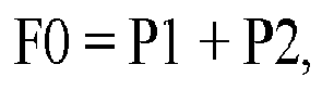


Each entry in T1 will contain the following:
| A | B | Result |
| [Ai,Aj] | [Bi,Bj] | F0,P1 |
| [Ak,Al] | [Bk,Bl] | F0,P2 |
| C | D | Result |
| [Ci,Cj] | [Di,Dj] | F0,P1 |
| [Ck,Cl] | [Dk,Dl] | F0,P2 |

| R1 | R2 | Result |
| F0,P1 | F0,P1 | Match |
| F0,P1 | F0,P2 | No Match |
| F0,P2 | F0,P1 | No match |
| F0,P2 | F0,P2 | Match |


- Assuming Aj = Ak + 2, and Ai < Ak.
- Calculate intersection between [Ai,Aj] and [Ak,Al] = [Ak,Ak+2]
- Create non-overlapping sets that represent [Ai,Al] using intersection: [Ai,Ak-1], [Ak,Ak+2], and [Ak+3,Al].
- Generate
- P1 = P11 or P12, and
- P2 = P21 or P22, where


- Assuming Bj = Bk + 2, and Bi < Bk.
- Calculate intersection between [Bi,Bj] and [Bk,Bl] = [Bk,Bk+2]
- Non-overlapping sets that represent [Bi,Bl] using intersection: [Bi,Bk-l], [Bk,Bk+2], and [Bk+3,Bl].
- Generate
- P1 = P111 or P112 or P121 or P122, and
- P2 = P211 or P212 or P221 or P222, where




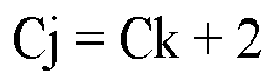
- Assuming Cj = Ck + 2, and Ci < Ck.
- Calculate intersection between [Ci,Cj] and [Ck,Cl] = [Ck,Ck+2]
- Non-overlapping sets that represent [Ci,Cl] using intersection: [Ci,Ck-1], [Ck,Ck+2], and [Ck+3,Cl].
- Generate
- P1 = P1111 or P1112 or P1121 or P1122 or P1211 or P1212 or P1221 or P1222, and
- P2 = P2111 or P2112 or P2121 or P2122 or P2211 or P2212 or P2221 or P2222, where


- Assuming Dj = Dk + 2, and Di < Dk.
- Calculate intersection between [Di,Dj] and [Dk,Dl] = [Dk,Dk+2]
- Non-overlapping sets that represent [Di,Dl] using intersection: [Di,Dk-1], [Dk,Dk+2], and [Dk+3,Dl].
- Generate
- P1 = P11111 or P11112 or P11121 or P11122 or P11211 or P11212 or P11221 or P11222 or
- P12111 or P12112 or P12121 or P12122 or P12211 or P12212 or P12221 or P12222, and
- P2 = P21111 or P21112 or P21121 or P21122 or P21211 or P21212 or P21221 or P21222 or
- P22111 or P22112 or P22121 or P22122 or P22211 or P22212 or P22221 or P22222, where

















- Generate
- P3 = P12222, result F1P1 F2P1, and
- P1-P3 = P11111 or P11112 or P11121 or P11122 or P11211 or P11212 or P11221 or
- P11222 or
- P12111 or P12112 or P12121 or P12122 or P12211 or P12212 or P12221 and
- P2-P3 = P21112 or P21121 or P21122 or P21211 or P21212 or P21221 or P21222 or
- P22111 or P22112 or P22121 or P22122 or P22211 or P22212 or P22221 or P22222, where











- Generate
- P3 = P12222, result F1P1 F2P1, and
- P1-P3 = P1111 or P1112 or P1121 or P1122 or P1211 or P1212 or P1221 or P12221, and
- P2-P3 = P21112 or P2112 or P2121 or P2122 or P2211 or P2212 or P2221 or P2222, where


- Generate
- P3 = P12222, result F1P1 F2P1, and
- P1-P3 = P111 or P112 or P121 or P1221 or P12221 and
- P2-P3 = P21112 or P2112 or P212 or P221 or P222, where





- Generate
- P3 = P12222, result F1P1 F2P1, and
- P1-P3 = P11 or P121 or P1221 or P12221, and
- P2-P3 = P21112 or P2112 or P212 or P22, where





- P1-P3 = P11 or P121 or P1221 or P12221
- P2-P3 = P21112 or P2112 or P212 or P22
- P3 = P12222, result F1P1 F2P1













Claims (19)
- A method for generating a binary tree from a filter expression, comprising:defining an operator stack in a memory, the operator stack adapted to store binary logical operators;defining a value stack in the memory, the value stack adapted to contain pointers to nodes of a filter expression tree;parsing the filter expression on an element-by-element basis, elements of the filter expression comprising operators and values;if a next element in the filter expression is a value, then adding the value to the value stack; andif the next element in the filter expression is an operator, then comparing the next element to a top element in the operator stack, and performing an action defined a decision table based upon the next element and the top element.
- The method of claim 1, wherein the action defined in the decision table is a shift function in which the next element is added to the operator stack.
- The method of claim 1, wherein the next element is an operator and the action defined in the decision table is a reduce function, and wherein the operator is applied to the top two values in the value stack.
- The method of claim 3, further comprising:adding a new value to the value stack, the new value corresponding to the operator applied to the top two values.
- The method of claim 1, wherein the action defined in the decision table is an accept function, and further comprising:removing the binary tree from the value stack.
- The method of claim 5, further comprising:converting the binary tree to a disjunctive normal form.
- The method of claim 1, wherein the operators comprise AND, OR, and NOT operators.
- The method of claim 1, wherein the values represent relational expressions.
- The method of claim 1, wherein the values represent results of combined logical and relational expressions.
- A method for generating a disjunctive normal form (DNF) of a filter expression from a binary tree representation of the filter expression, comprising:removing all NOT operations from nodes of the binary tree;defining stacks in a memory corresponding to a left sub-tree stack (L-stack), a right sub-tree stack (R-stack), a result of left sub-tree stack (RL-stack), and a result of right sub-tree stack (RR-stack);performing a post-order traversal of the nodes of the binary tree in which each node of binary tree is visited;if a visited node is a leaf node, then insert the operation allocated to the leaf node to the L-stack if the leaf node is a left child or insert the operation allocated to the leaf node to the R-stack if the leaf node is a right child; andif the visited node is a non-leaf node, then processing the non-leaf node based upon whether the operation contains an OR operation or an AND operation.
- The method of claim 10, further comprising:if the non-leaf node contains an OR operation and children nodes of the non-leaf node are leaf nodes, thenmoving all nodes from the R-stack and L-stack into the RL-stack if the non-leaf node is a left child ormoving all nodes from the R-stack and L-stack into the RR-stack if the non-leaf node is a right child.
- The method of claim 10, further comprising:if the non-leaf node contains an OR operation and children nodes of the non-leaf node are not leaf nodes, thenmoving all nodes from the RR-stack and the RL-stack into the RL-stack if the non-leaf node is a left child ormoving all nodes from the RR-stack and the RL-stack into the RR-stack if the non-leaf node is a right child.
- The method of claim 10, further comprising:if the non-leaf node contains an AND operation and children nodes of the non-leaf node are leaf nodes, thencombining every node in the R-stack with every node in the L-stack to create a single conjunctive clause.
- The method of claim 13, further comprising:inserting the single conjunctive clause into the RL-stack if the non-leaf node is a left child, orinserting the single conjunctive clause into the RR-stack if the non-leaf node is a right child.
- The method of claim 10, further comprising:processing a root node of the binary tree, wherein the root node is treated as a left child during processing; andremoving the disjunctive normal form of the filter expression from the RL-stack.
- The method of claim 10, further comprising:identifying overlapping keys from the disjunctive normal form of the filter expression.
- A computer-readable storage medium comprising instructions for converting a filter expression to a disjunctive normal form, wherein the instructions, when executed, cause a processor to perform actions comprising:defining an operator stack in a memory, the operator stack adapted to store binary logical operators;defining a value stack in the memory, the value stack adapted to contain pointers to nodes of a filter expression tree;parsing the filter expression on an element-by-element basis, elements of the filter expression comprising operators and values, wherein for each next element in the filter expression:if the next element in the filter expression is a value, then adding the value to the value stack; andif the next element in the filter expression is an operator, then comparing the next element to a top element in the operator stack, and performing an action defined a decision table based upon the next element and the top element;removing a completed binary tree from the value stack;defining stacks in a memory corresponding to a left sub-tree stack (L-stack), a right sub-tree stack (R-stack), a result of left sub-tree stack (RL-stack), and a result of right sub-tree stack (RR-stack);performing a post-order traversal of the nodes of the completed binary tree in which each node of completed binary tree is visited, wherein during the post-order traversal:if a visited node is a leaf node, then insert the operation allocated to the leaf node to the L-stack if the leaf node is a left child or insert the operation allocated to the leaf node to the R-stack if the leaf node is a right child; andif the visited node is a non-leaf node, then processing the non-leaf node based upon whether the operation contains an OR operation or an AND operation, wherein the processing moves data into the RL-stack or the RR-stack;processing a root node of the binary tree;removing the disjunctive normal form of the filter expression from the RL-stack or the RR-stack corresponding to the root node; andidentifying overlapping keys from the disjunctive normal form of the filter expression.
- The computer-readable storage medium of claim 17, further comprising:if the non-leaf node contains an OR operation and children nodes of the non-leaf node are leaf nodes, thenmoving all nodes from the R-stack and L-stack into the RL-stack if the non-leaf node is a left child ormoving all nodes from the R-stack and L-stack into the RR-stack if the non-leaf node is a right child;if the non-leaf node contains an OR operation and children nodes of the non-leaf node are not leaf nodes, thenmoving all nodes from the RR-stack and the RL-stack into the RL-stack if the non-leaf node is a left child ormoving all nodes from the RR-stack and the RL-stack into the RR-stack if the non-leaf node is a right child; andif the non-leaf node contains an AND operation and children nodes of the non-leaf node are leaf nodes, thencombining every node in the R-stack with every node in the L-stack to create a single conjunctive clause;inserting the single conjunctive clause into the RL-stack if the non-leaf node is a left child, orinserting the single conjunctive clause into the RR-stack if the non-leaf node is a right child.
- The computer-readable storage medium of claim 17, further comprising:removing all NOT operations from nodes of the completed binary tree.
Applications Claiming Priority (1)
| Application Number | Priority Date | Filing Date | Title |
|---|---|---|---|
| US13/024,707 US8375031B2 (en) | 2011-02-10 | 2011-02-10 | Lossless real-time line-rate filtering using PCAP style filters and hardware assisted patricia trees |
Publications (3)
| Publication Number | Publication Date |
|---|---|
| EP2487861A2 true EP2487861A2 (en) | 2012-08-15 |
| EP2487861A3 EP2487861A3 (en) | 2014-01-01 |
| EP2487861B1 EP2487861B1 (en) | 2017-12-13 |
Family
ID=45566820
Family Applications (1)
| Application Number | Title | Priority Date | Filing Date |
|---|---|---|---|
| EP12150771.9A Active EP2487861B1 (en) | 2011-02-10 | 2012-01-11 | Lossless real-time line-rate filtering using pcap style filters and hardware assisted patricia trees |
Country Status (4)
| Country | Link |
|---|---|
| US (1) | US8375031B2 (en) |
| EP (1) | EP2487861B1 (en) |
| JP (1) | JP2012178151A (en) |
| CN (1) | CN102710491B (en) |
Families Citing this family (6)
| Publication number | Priority date | Publication date | Assignee | Title |
|---|---|---|---|---|
| KR101993835B1 (en) * | 2013-02-25 | 2019-06-27 | 삼성전자주식회사 | Method and apparatus for adaptive stack management |
| US9426071B1 (en) * | 2013-08-22 | 2016-08-23 | Fireeye, Inc. | Storing network bidirectional flow data and metadata with efficient processing technique |
| CN107133330B (en) * | 2017-05-10 | 2021-02-02 | 苏州浪潮智能科技有限公司 | Data binarization processing method and device |
| CN107704567A (en) * | 2017-09-29 | 2018-02-16 | 郑州云海信息技术有限公司 | A kind of analytic method of binary file, device, equipment and storage medium |
| CN111061482B (en) * | 2019-10-24 | 2023-12-08 | 贝壳技术有限公司 | Methods, devices, storage media and electronic equipment for parsing parameters in strings |
| CN110912752B (en) * | 2019-12-06 | 2022-03-29 | 成都安恒信息技术有限公司 | Network fault intelligent positioning analysis method based on network packet capturing |
Family Cites Families (12)
| Publication number | Priority date | Publication date | Assignee | Title |
|---|---|---|---|---|
| US6120552A (en) | 1998-05-27 | 2000-09-19 | International Business Machines Corporation | Method to exhibit parallelism for computer implementation of computational processing |
| EP2197211A3 (en) * | 2000-12-22 | 2010-08-25 | Siemens Aktiengesellschaft | Method for improving the functionality of the binary representation of MPEG-7 and other XML-based content descriptions |
| WO2002097667A2 (en) * | 2001-05-31 | 2002-12-05 | Lixto Software Gmbh | Visual and interactive wrapper generation, automated information extraction from web pages, and translation into xml |
| US7551629B2 (en) * | 2002-03-28 | 2009-06-23 | Precache, Inc. | Method and apparatus for propagating content filters for a publish-subscribe network |
| US7415596B2 (en) | 2003-01-24 | 2008-08-19 | Gigafin Networks, Inc. | Parser table/production rule table configuration using CAM and SRAM |
| US7251722B2 (en) * | 2004-05-11 | 2007-07-31 | Mistletoe Technologies, Inc. | Semantic processor storage server architecture |
| US8387029B2 (en) | 2005-07-25 | 2013-02-26 | Hercules Software, Llc | Direct execution virtual machine |
| US20080091409A1 (en) | 2006-10-16 | 2008-04-17 | Microsoft Corporation | Customizable mathematic expression parser and evaluator |
| US7636697B1 (en) * | 2007-01-29 | 2009-12-22 | Ailive Inc. | Method and system for rapid evaluation of logical expressions |
| US8086597B2 (en) * | 2007-06-28 | 2011-12-27 | International Business Machines Corporation | Between matching |
| EP2096534A1 (en) * | 2008-02-29 | 2009-09-02 | ITI Scotland Limited | System representation and handling techniques |
| US8516458B2 (en) * | 2008-02-29 | 2013-08-20 | Iti Scotland Limited | System representation and handling techniques |
-
2011
- 2011-02-10 US US13/024,707 patent/US8375031B2/en active Active
-
2012
- 2012-01-11 EP EP12150771.9A patent/EP2487861B1/en active Active
- 2012-02-10 JP JP2012027065A patent/JP2012178151A/en active Pending
- 2012-02-10 CN CN201210032268.4A patent/CN102710491B/en active Active
Non-Patent Citations (1)
| Title |
|---|
| None |
Also Published As
| Publication number | Publication date |
|---|---|
| JP2012178151A (en) | 2012-09-13 |
| CN102710491B (en) | 2017-05-31 |
| CN102710491A (en) | 2012-10-03 |
| EP2487861B1 (en) | 2017-12-13 |
| US20120209862A1 (en) | 2012-08-16 |
| US8375031B2 (en) | 2013-02-12 |
| EP2487861A3 (en) | 2014-01-01 |
Similar Documents
| Publication | Publication Date | Title |
|---|---|---|
| EP2487861B1 (en) | Lossless real-time line-rate filtering using pcap style filters and hardware assisted patricia trees | |
| US9762544B2 (en) | Reverse NFA generation and processing | |
| US20220124070A1 (en) | Methods, Systems, and Computer Readable Media for Adaptive Packet Filtering | |
| EP2486704B1 (en) | Configurable frame processing pipeline in a packet switch | |
| US9563399B2 (en) | Generating a non-deterministic finite automata (NFA) graph for regular expression patterns with advanced features | |
| US9336328B2 (en) | Content search mechanism that uses a deterministic finite automata (DFA) graph, a DFA state machine, and a walker process | |
| US5916305A (en) | Pattern recognition in data communications using predictive parsers | |
| EP2215565B1 (en) | Deterministic finite automata (dfa) graph compression | |
| US8504510B2 (en) | State machine compression for scalable pattern matching | |
| US20140369363A1 (en) | Apparatus and Method for Uniquely Enumerating Paths in a Parse Tree | |
| US20030123459A1 (en) | Efficiency masked matching | |
| US9647947B2 (en) | Block mask register key processing by compiling data structures to traverse rules and creating a new rule set | |
| Meiners et al. | Flowsifter: A counting automata approach to layer 7 field extraction for deep flow inspection | |
| CN106062740B (en) | Method and device for generating multiple index data fields | |
| WO2005064495A1 (en) | Multi-dimensional packet classification by disjunct filter sets whereby the sets are based on wilcard properties | |
| US20140208076A1 (en) | Dfa compression and execution | |
| Zazo et al. | Automated synthesis of FPGA-based packet filters for 100 Gbps network monitoring applications | |
| Ni et al. | A fast multi-pattern matching algorithm for deep packet inspection on a network processor | |
| Liu et al. | A few bits are enough-ASIC friendly regular expression matching for high speed network security systems | |
| Hnaif et al. | Parallel Quick Search Algorithm to Speed Packet Payload Filtering in NIDS | |
| CN121396855A (en) | Network asset detection method, device, equipment and storage medium | |
| Pletzer et al. | Efficient End-to-End Intrusion Detection with Packet and Flow-Level Mamba Sequence Models | |
| Hnaif et al. | Parallel quick search algorithm to speed packet payload filtering in NIDS | |
| Cerrato et al. | Filtering network traffic based on protocol encapsulation rules | |
| Kellerhals | Parameterized Algorithms for Network Flows |
Legal Events
| Date | Code | Title | Description |
|---|---|---|---|
| PUAI | Public reference made under article 153(3) epc to a published international application that has entered the european phase |
Free format text: ORIGINAL CODE: 0009012 |
|
| AK | Designated contracting states |
Kind code of ref document: A2 Designated state(s): AL AT BE BG CH CY CZ DE DK EE ES FI FR GB GR HR HU IE IS IT LI LT LU LV MC MK MT NL NO PL PT RO RS SE SI SK SM TR |
|
| AX | Request for extension of the european patent |
Extension state: BA ME |
|
| RIC1 | Information provided on ipc code assigned before grant |
Ipc: H04L 29/06 20060101AFI20120920BHEP Ipc: G06F 9/45 20060101ALI20120920BHEP |
|
| PUAL | Search report despatched |
Free format text: ORIGINAL CODE: 0009013 |
|
| AK | Designated contracting states |
Kind code of ref document: A3 Designated state(s): AL AT BE BG CH CY CZ DE DK EE ES FI FR GB GR HR HU IE IS IT LI LT LU LV MC MK MT NL NO PL PT RO RS SE SI SK SM TR |
|
| AX | Request for extension of the european patent |
Extension state: BA ME |
|
| RIC1 | Information provided on ipc code assigned before grant |
Ipc: H04L 29/06 20060101AFI20131127BHEP Ipc: G06F 9/45 20060101ALI20131127BHEP |
|
| 17P | Request for examination filed |
Effective date: 20140701 |
|
| RBV | Designated contracting states (corrected) |
Designated state(s): AL AT BE BG CH CY CZ DE DK EE ES FI FR GB GR HR HU IE IS IT LI LT LU LV MC MK MT NL NO PL PT RO RS SE SI SK SM TR |
|
| RAP1 | Party data changed (applicant data changed or rights of an application transferred) |
Owner name: NETSCOUT SYSTEMS TEXAS, LLC |
|
| GRAP | Despatch of communication of intention to grant a patent |
Free format text: ORIGINAL CODE: EPIDOSNIGR1 |
|
| STAA | Information on the status of an ep patent application or granted ep patent |
Free format text: STATUS: GRANT OF PATENT IS INTENDED |
|
| INTG | Intention to grant announced |
Effective date: 20170704 |
|
| GRAS | Grant fee paid |
Free format text: ORIGINAL CODE: EPIDOSNIGR3 |
|
| GRAA | (expected) grant |
Free format text: ORIGINAL CODE: 0009210 |
|
| STAA | Information on the status of an ep patent application or granted ep patent |
Free format text: STATUS: THE PATENT HAS BEEN GRANTED |
|
| AK | Designated contracting states |
Kind code of ref document: B1 Designated state(s): AL AT BE BG CH CY CZ DE DK EE ES FI FR GB GR HR HU IE IS IT LI LT LU LV MC MK MT NL NO PL PT RO RS SE SI SK SM TR |
|
| REG | Reference to a national code |
Ref country code: GB Ref legal event code: FG4D |
|
| REG | Reference to a national code |
Ref country code: AT Ref legal event code: REF Ref document number: 955344 Country of ref document: AT Kind code of ref document: T Effective date: 20171215 Ref country code: CH Ref legal event code: EP |
|
| REG | Reference to a national code |
Ref country code: IE Ref legal event code: FG4D |
|
| REG | Reference to a national code |
Ref country code: DE Ref legal event code: R096 Ref document number: 602012040754 Country of ref document: DE |
|
| REG | Reference to a national code |
Ref country code: NL Ref legal event code: MP Effective date: 20171213 |
|
| REG | Reference to a national code |
Ref country code: LT Ref legal event code: MG4D |
|
| PG25 | Lapsed in a contracting state [announced via postgrant information from national office to epo] |
Ref country code: SE Free format text: LAPSE BECAUSE OF FAILURE TO SUBMIT A TRANSLATION OF THE DESCRIPTION OR TO PAY THE FEE WITHIN THE PRESCRIBED TIME-LIMIT Effective date: 20171213 Ref country code: LT Free format text: LAPSE BECAUSE OF FAILURE TO SUBMIT A TRANSLATION OF THE DESCRIPTION OR TO PAY THE FEE WITHIN THE PRESCRIBED TIME-LIMIT Effective date: 20171213 Ref country code: NO Free format text: LAPSE BECAUSE OF FAILURE TO SUBMIT A TRANSLATION OF THE DESCRIPTION OR TO PAY THE FEE WITHIN THE PRESCRIBED TIME-LIMIT Effective date: 20180313 Ref country code: FI Free format text: LAPSE BECAUSE OF FAILURE TO SUBMIT A TRANSLATION OF THE DESCRIPTION OR TO PAY THE FEE WITHIN THE PRESCRIBED TIME-LIMIT Effective date: 20171213 |
|
| REG | Reference to a national code |
Ref country code: AT Ref legal event code: MK05 Ref document number: 955344 Country of ref document: AT Kind code of ref document: T Effective date: 20171213 |
|
| PG25 | Lapsed in a contracting state [announced via postgrant information from national office to epo] |
Ref country code: HR Free format text: LAPSE BECAUSE OF FAILURE TO SUBMIT A TRANSLATION OF THE DESCRIPTION OR TO PAY THE FEE WITHIN THE PRESCRIBED TIME-LIMIT Effective date: 20171213 Ref country code: LV Free format text: LAPSE BECAUSE OF FAILURE TO SUBMIT A TRANSLATION OF THE DESCRIPTION OR TO PAY THE FEE WITHIN THE PRESCRIBED TIME-LIMIT Effective date: 20171213 Ref country code: GR Free format text: LAPSE BECAUSE OF FAILURE TO SUBMIT A TRANSLATION OF THE DESCRIPTION OR TO PAY THE FEE WITHIN THE PRESCRIBED TIME-LIMIT Effective date: 20180314 Ref country code: BG Free format text: LAPSE BECAUSE OF FAILURE TO SUBMIT A TRANSLATION OF THE DESCRIPTION OR TO PAY THE FEE WITHIN THE PRESCRIBED TIME-LIMIT Effective date: 20180313 Ref country code: RS Free format text: LAPSE BECAUSE OF FAILURE TO SUBMIT A TRANSLATION OF THE DESCRIPTION OR TO PAY THE FEE WITHIN THE PRESCRIBED TIME-LIMIT Effective date: 20171213 |
|
| PG25 | Lapsed in a contracting state [announced via postgrant information from national office to epo] |
Ref country code: NL Free format text: LAPSE BECAUSE OF FAILURE TO SUBMIT A TRANSLATION OF THE DESCRIPTION OR TO PAY THE FEE WITHIN THE PRESCRIBED TIME-LIMIT Effective date: 20171213 |
|
| PG25 | Lapsed in a contracting state [announced via postgrant information from national office to epo] |
Ref country code: ES Free format text: LAPSE BECAUSE OF FAILURE TO SUBMIT A TRANSLATION OF THE DESCRIPTION OR TO PAY THE FEE WITHIN THE PRESCRIBED TIME-LIMIT Effective date: 20171213 Ref country code: CZ Free format text: LAPSE BECAUSE OF FAILURE TO SUBMIT A TRANSLATION OF THE DESCRIPTION OR TO PAY THE FEE WITHIN THE PRESCRIBED TIME-LIMIT Effective date: 20171213 Ref country code: CY Free format text: LAPSE BECAUSE OF FAILURE TO SUBMIT A TRANSLATION OF THE DESCRIPTION OR TO PAY THE FEE WITHIN THE PRESCRIBED TIME-LIMIT Effective date: 20171213 Ref country code: EE Free format text: LAPSE BECAUSE OF FAILURE TO SUBMIT A TRANSLATION OF THE DESCRIPTION OR TO PAY THE FEE WITHIN THE PRESCRIBED TIME-LIMIT Effective date: 20171213 Ref country code: SK Free format text: LAPSE BECAUSE OF FAILURE TO SUBMIT A TRANSLATION OF THE DESCRIPTION OR TO PAY THE FEE WITHIN THE PRESCRIBED TIME-LIMIT Effective date: 20171213 |
|
| PG25 | Lapsed in a contracting state [announced via postgrant information from national office to epo] |
Ref country code: RO Free format text: LAPSE BECAUSE OF FAILURE TO SUBMIT A TRANSLATION OF THE DESCRIPTION OR TO PAY THE FEE WITHIN THE PRESCRIBED TIME-LIMIT Effective date: 20171213 Ref country code: IT Free format text: LAPSE BECAUSE OF FAILURE TO SUBMIT A TRANSLATION OF THE DESCRIPTION OR TO PAY THE FEE WITHIN THE PRESCRIBED TIME-LIMIT Effective date: 20171213 Ref country code: AT Free format text: LAPSE BECAUSE OF FAILURE TO SUBMIT A TRANSLATION OF THE DESCRIPTION OR TO PAY THE FEE WITHIN THE PRESCRIBED TIME-LIMIT Effective date: 20171213 Ref country code: SM Free format text: LAPSE BECAUSE OF FAILURE TO SUBMIT A TRANSLATION OF THE DESCRIPTION OR TO PAY THE FEE WITHIN THE PRESCRIBED TIME-LIMIT Effective date: 20171213 Ref country code: IS Free format text: LAPSE BECAUSE OF FAILURE TO SUBMIT A TRANSLATION OF THE DESCRIPTION OR TO PAY THE FEE WITHIN THE PRESCRIBED TIME-LIMIT Effective date: 20180413 Ref country code: PL Free format text: LAPSE BECAUSE OF FAILURE TO SUBMIT A TRANSLATION OF THE DESCRIPTION OR TO PAY THE FEE WITHIN THE PRESCRIBED TIME-LIMIT Effective date: 20171213 |
|
| REG | Reference to a national code |
Ref country code: CH Ref legal event code: PL |
|
| REG | Reference to a national code |
Ref country code: DE Ref legal event code: R097 Ref document number: 602012040754 Country of ref document: DE |
|
| PG25 | Lapsed in a contracting state [announced via postgrant information from national office to epo] |
Ref country code: MC Free format text: LAPSE BECAUSE OF FAILURE TO SUBMIT A TRANSLATION OF THE DESCRIPTION OR TO PAY THE FEE WITHIN THE PRESCRIBED TIME-LIMIT Effective date: 20171213 |
|
| PLBE | No opposition filed within time limit |
Free format text: ORIGINAL CODE: 0009261 |
|
| STAA | Information on the status of an ep patent application or granted ep patent |
Free format text: STATUS: NO OPPOSITION FILED WITHIN TIME LIMIT |
|
| PG25 | Lapsed in a contracting state [announced via postgrant information from national office to epo] |
Ref country code: LU Free format text: LAPSE BECAUSE OF NON-PAYMENT OF DUE FEES Effective date: 20180111 Ref country code: FR Free format text: LAPSE BECAUSE OF NON-PAYMENT OF DUE FEES Effective date: 20180213 |
|
| REG | Reference to a national code |
Ref country code: IE Ref legal event code: MM4A |
|
| REG | Reference to a national code |
Ref country code: FR Ref legal event code: ST Effective date: 20180928 |
|
| REG | Reference to a national code |
Ref country code: BE Ref legal event code: MM Effective date: 20180131 |
|
| 26N | No opposition filed |
Effective date: 20180914 |
|
| PG25 | Lapsed in a contracting state [announced via postgrant information from national office to epo] |
Ref country code: DK Free format text: LAPSE BECAUSE OF FAILURE TO SUBMIT A TRANSLATION OF THE DESCRIPTION OR TO PAY THE FEE WITHIN THE PRESCRIBED TIME-LIMIT Effective date: 20171213 Ref country code: LI Free format text: LAPSE BECAUSE OF NON-PAYMENT OF DUE FEES Effective date: 20180131 Ref country code: CH Free format text: LAPSE BECAUSE OF NON-PAYMENT OF DUE FEES Effective date: 20180131 Ref country code: BE Free format text: LAPSE BECAUSE OF NON-PAYMENT OF DUE FEES Effective date: 20180131 |
|
| PG25 | Lapsed in a contracting state [announced via postgrant information from national office to epo] |
Ref country code: IE Free format text: LAPSE BECAUSE OF NON-PAYMENT OF DUE FEES Effective date: 20180111 |
|
| PG25 | Lapsed in a contracting state [announced via postgrant information from national office to epo] |
Ref country code: SI Free format text: LAPSE BECAUSE OF FAILURE TO SUBMIT A TRANSLATION OF THE DESCRIPTION OR TO PAY THE FEE WITHIN THE PRESCRIBED TIME-LIMIT Effective date: 20171213 |
|
| PG25 | Lapsed in a contracting state [announced via postgrant information from national office to epo] |
Ref country code: MT Free format text: LAPSE BECAUSE OF NON-PAYMENT OF DUE FEES Effective date: 20180111 |
|
| PG25 | Lapsed in a contracting state [announced via postgrant information from national office to epo] |
Ref country code: TR Free format text: LAPSE BECAUSE OF FAILURE TO SUBMIT A TRANSLATION OF THE DESCRIPTION OR TO PAY THE FEE WITHIN THE PRESCRIBED TIME-LIMIT Effective date: 20171213 |
|
| PG25 | Lapsed in a contracting state [announced via postgrant information from national office to epo] |
Ref country code: PT Free format text: LAPSE BECAUSE OF FAILURE TO SUBMIT A TRANSLATION OF THE DESCRIPTION OR TO PAY THE FEE WITHIN THE PRESCRIBED TIME-LIMIT Effective date: 20171213 Ref country code: HU Free format text: LAPSE BECAUSE OF FAILURE TO SUBMIT A TRANSLATION OF THE DESCRIPTION OR TO PAY THE FEE WITHIN THE PRESCRIBED TIME-LIMIT; INVALID AB INITIO Effective date: 20120111 |
|
| PG25 | Lapsed in a contracting state [announced via postgrant information from national office to epo] |
Ref country code: MK Free format text: LAPSE BECAUSE OF NON-PAYMENT OF DUE FEES Effective date: 20171213 |
|
| PG25 | Lapsed in a contracting state [announced via postgrant information from national office to epo] |
Ref country code: AL Free format text: LAPSE BECAUSE OF FAILURE TO SUBMIT A TRANSLATION OF THE DESCRIPTION OR TO PAY THE FEE WITHIN THE PRESCRIBED TIME-LIMIT Effective date: 20171213 |
|
| REG | Reference to a national code |
Ref country code: DE Ref legal event code: R079 Ref document number: 602012040754 Country of ref document: DE Free format text: PREVIOUS MAIN CLASS: H04L0029060000 Ipc: H04L0065000000 |
|
| P01 | Opt-out of the competence of the unified patent court (upc) registered |
Effective date: 20231024 |
|
| PGFP | Annual fee paid to national office [announced via postgrant information from national office to epo] |
Ref country code: GB Payment date: 20260127 Year of fee payment: 15 |
|
| PGFP | Annual fee paid to national office [announced via postgrant information from national office to epo] |
Ref country code: DE Payment date: 20260128 Year of fee payment: 15 |