EP2487562A1 - Optical navigation module with alignment features - Google Patents
Optical navigation module with alignment features Download PDFInfo
- Publication number
- EP2487562A1 EP2487562A1 EP11154134A EP11154134A EP2487562A1 EP 2487562 A1 EP2487562 A1 EP 2487562A1 EP 11154134 A EP11154134 A EP 11154134A EP 11154134 A EP11154134 A EP 11154134A EP 2487562 A1 EP2487562 A1 EP 2487562A1
- Authority
- EP
- European Patent Office
- Prior art keywords
- optical navigation
- navigation module
- alignment
- flange
- mobile device
- Prior art date
- Legal status (The legal status is an assumption and is not a legal conclusion. Google has not performed a legal analysis and makes no representation as to the accuracy of the status listed.)
- Granted
Links
Images



Classifications
-
- G—PHYSICS
- G06—COMPUTING OR CALCULATING; COUNTING
- G06F—ELECTRIC DIGITAL DATA PROCESSING
- G06F1/00—Details not covered by groups G06F3/00 - G06F13/00 and G06F21/00
- G06F1/16—Constructional details or arrangements
- G06F1/1613—Constructional details or arrangements for portable computers
- G06F1/1633—Constructional details or arrangements of portable computers not specific to the type of enclosures covered by groups G06F1/1615 - G06F1/1626
- G06F1/1684—Constructional details or arrangements related to integrated I/O peripherals not covered by groups G06F1/1635 - G06F1/1675
- G06F1/169—Constructional details or arrangements related to integrated I/O peripherals not covered by groups G06F1/1635 - G06F1/1675 the I/O peripheral being an integrated pointing device, e.g. trackball in the palm rest area, mini-joystick integrated between keyboard keys, touch pads or touch stripes
-
- G—PHYSICS
- G06—COMPUTING OR CALCULATING; COUNTING
- G06F—ELECTRIC DIGITAL DATA PROCESSING
- G06F3/00—Input arrangements for transferring data to be processed into a form capable of being handled by the computer; Output arrangements for transferring data from processing unit to output unit, e.g. interface arrangements
- G06F3/01—Input arrangements or combined input and output arrangements for interaction between user and computer
- G06F3/03—Arrangements for converting the position or the displacement of a member into a coded form
- G06F3/033—Pointing devices displaced or positioned by the user, e.g. mice, trackballs, pens or joysticks; Accessories therefor
- G06F3/0354—Pointing devices displaced or positioned by the user, e.g. mice, trackballs, pens or joysticks; Accessories therefor with detection of two-dimensional [2D] relative movements between the device, or an operating part thereof, and a plane or surface, e.g. 2D mice, trackballs, pens or pucks
- G06F3/03547—Touch pads, in which fingers can move on a surface
Definitions
- the present disclosure relates to mobile devices, and more specifically to an optical navigation module with alignment features for a mobile device.
- Mobile devices are becoming more prevalent and more advanced.
- Mobile devices can include, but are not limited to, cellular telephones, smart telephones, wireless personal digital assistants (PDAs), and laptop computers with wireless 802.11 or Bluetooth capabilities. These devices can run on a wide variety of networks from data-only networks such as Mobitex ® and DataTAC ® networks to complex voice and data networks such as GSM/GPRS, CDMA, EDGE, UMTS and CDMA2000 networks.
- data-only networks such as Mobitex ® and DataTAC ® networks
- complex voice and data networks such as GSM/GPRS, CDMA, EDGE, UMTS and CDMA2000 networks.
- GSM/GPRS Global System for Mobile Communications
- CDMA Code Division Multiple Access
- EDGE Code Division Multiple Access
- UMTS Code Division Multiple Access 2000
- optical navigation tools such as optical navigation pads and optical jog balls
- Conventional optical navigation tools can use an electrical connector to communicatively couple an optical navigation tool and a processor to control navigation among items displayed on the display screen of the mobile device. Due to imprecision in the length of these electrical connectors, some optical navigation tools are not properly aligned after fabrication. Specifically, due to the imprecision in the length of the electrical connector, the optical navigation tool can be tilted or angled towards one of the sides of the mobile device. For example, in the event the electrical connector is longer than desired, the side of the optical navigation tool having the coupled electrical connector can be higher than the opposite side of the optical navigation tool.
- the side of the optical navigation tool having the coupled electrical connector can be lower than the opposite side of the optical navigation tool.
- the tactile feel for the optical navigation tool is poor due to improper support in the z-direction or z-axis.
- Figure 1 is a front view of a mobile device having an optical navigation tool in accordance with an exemplary implementation
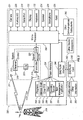
- FIG. 2 is a block diagram of a mobile device in a communication network in accordance with an exemplary implementation
- Figure 3 is a perspective view of an optical navigation module for a mobile device in accordance with an exemplary implementation
- Figure 4 is a cross section view of an alignment flange in accordance with an exemplary implementation.
- Figure 5 is a cross section of an optical navigation module for a mobile device in accordance with an exemplary implementation.
- Coupled is defined as connected, whether directly or indirectly through intervening components, and is not necessarily limited to physical connections.
- communicately coupled is defined as connected, whether directly or indirectly through intervening components, is not necessarily limited to a physical connection, and allows for the transfer of data.
- mobile device is defined as any electronic device that is capable of at least accepting information entries from a user and includes the device's own power source.
- wireless communication means communication that occurs without wires using electromagnetic radiation.
- memory refers to transitory memory and non-transitory memory.
- non-transitory memory can be implemented as Random Access Memory (RAM), Read-Only Memory (ROM), flash, ferromagnetic, phase-change memory, and other non-transitory memory technologies.
- the present disclosure describes an optical navigation module with alignment features for a mobile device.
- the optical navigation module can include a rigid flange having a top surface.
- An optical navigation unit can be coupled to the top surface of the rigid flange with an electrical connector electrically coupled to the optical navigation unit.
- An alignment flange can be coupled to the rigid flange with the alignment feature including one or more alignment features.
- the alignment feature can be a hole adapted to receive an alignment pin to hold and align the optical navigation module.
- the optical navigation module can reduce tilting caused by imprecision in the length of the electrical connector.
- the optical navigation module can provide support in the z-direction or z-axis which can result in improved tactile feel for the optical navigation module.
- the mobile device 100 can have a reduced QWERTY keyboard 132.
- Each key of the keyboard 132 can be associated with at least one indicia representing an alphabetic character, a numeral, or a command (such as a space command, return command, or the like).
- the plurality of the keys having alphabetic characters can be arranged in a standard keyboard layout.
- This standard keyboard layout can be a QWERTY layout (as shown in Figure 1 ), a QZERTY layout, a QWERTZ layout, an AZERTY layout, a Dvorak layout, a Russian keyboard layout, a Chinese keyboard layout, or other similar layout.
- the keyboard layout can be based on the geographical region in which the handheld device is intended for sale. In some examples, the keyboard can be interchangeable such that the user can switch between layouts. In other examples, the keyboard is a virtual keyboard provided on a touch screen display (not shown).
- the exemplary mobile device 100 can be communicatively coupled to a wireless network 219 as exemplified in the block diagram of Figure 2 .
- a wireless network 219 as exemplified in the block diagram of Figure 2 .
- the mobile device 100 is a smart phone, however, in other embodiments, the mobile device 100 can be a personal digital assistant (PDA), laptop computer, desktop computer, tablet computer, server, or other mobile device capable of sending and receiving electronic messages.
- PDA personal digital assistant
- the mobile device 100 can have the lighted display 122 located above the keyboard 132 constituting a user input and suitable for accommodating textual input to the mobile device 100.
- the front face 170 of the mobile device 100 can have a navigation row 180.
- the mobile device 100 can be of a unibody construction, also known as a "candy-bar" design. In alternate embodiments, the mobile device 100 can be a "clamshell” or a "slider” design.
- the mobile device 100 can include an auxiliary input that acts as a cursor navigation tool 127 and which can be also exteriorly located upon the front face 170 of the mobile device 100.
- the front face location of the navigation tool 127 can allow the navigation tool 127 to be easily thumb-actuable or finger-actuable like the keys of the keyboard 132.
- An embodiment provides the navigation tool 127 in the form of the optical navigation module 121 having one or more sensors, such as a capacitive sensor, optical sensor, or both, which can be utilized to instruct two-dimensional or three-dimensional screen cursor movement in substantially any direction, as well as act as an actuator when the optical navigation module 121 is depressed like a button.
- the placement of the navigation tool 127 may be above the keyboard 132 and below the display screen 122; here, it can avoid interference during keyboarding and does not block the operator's view of the display screen 122 during use, for example, as shown in Figure 1 .
- the mobile device 100 can be configured to send and receive messages.
- the mobile device 100 includes a body 171 which can, in some embodiments, be configured to be held in one hand by an operator of the mobile device 100 during text entry.
- the display 122 is included which is located on the front face 170 of the body 171 and upon which information is displayed to the operator during text entry.
- the mobile device 100 can also be configured to send and receive voice communications such as mobile telephone calls.
- the mobile device 100 can also include a camera to allow the user to take electronic photographs which can be referred to as photos or pictures.
- the mobile device 100 can include a microprocessor 238 that controls the operation of the mobile device 100, such as facilitating communications, providing a graphical user interface, executing programs, and so forth.
- a communication subsystem 211 performs communication transmission and reception with the wireless network 219.
- the microprocessor 238 further can be coupled with an auxiliary input/output (I/O) subsystem 228.
- the microprocessor 238 can be coupled to a serial port (for example, a Universal Serial Bus port) 230 that facilitates communication with other devices or systems via the serial port 230.
- a serial port for example, a Universal Serial Bus port
- a display 122 can be communicatively coupled to the microprocessor 238 to facilitate display of information to an operator of the mobile device 100.
- the mobile device 100 is equipped with a keyboard 132, which can be physical or virtual (for example, displayed as images of keys rendered on a touch screen), the keyboard 132 can be communicatively coupled to the microprocessor 238.
- the mobile device 100 can include one or more speakers 234 and one or more microphones 236, which can advantageously be communicatively coupled to the microprocessor 238 and are discussed in further detail below.
- Other communication subsystems 240 and other mobile device subsystems 242 are generally indicated as communicatively coupled with the microprocessor 238.
- a communication subsystem 240 is a short-range communication system such as a BLUETOOTH ® communication module or a WI-FI ® communication module (a communication module in compliance with IEEE 802.11b, g or n) and associated circuits and components. Additionally, the microprocessor 238 can perform operating system functions and executes programs or software applications on the mobile device 100. In some implementations, not all of the above components are included in the mobile device 100.
- the auxiliary I/O subsystem 228 can take the form of one or more different navigation tools (multi-directional or single-directional), external I/O devices such as keyboards, and other subsystems capable of providing input or receiving output from the mobile device 100.
- the auxiliary I/O subsystem 228 can take the form of a variety of different navigation tools 127 (multi-directional or single-directional) such as an optical navigation module or tool 121 as illustrated in the exemplary embodiment shown in Figure 1 and shown in more detail in Figures 3-5 .
- a trackball, a thumbwheel, a navigation pad, a joystick, a touch-sensitive interface, or other I/O interface can be used.
- the navigation tool 127 can be located on a front surface 170 of the mobile device 100 or may be located on any exterior surface of the mobile device 100.
- Other auxiliary I/O subsystems can include external display devices and externally connected keyboards (not shown).
- auxiliary I/O subsystem 2208 While the above examples have been provided in relation to the auxiliary I/O subsystem 228, other subsystems capable of providing input or receiving output from the mobile device 100 are considered within the scope of this disclosure. Additionally, other keys may be placed along the side of the mobile device 100 to function as escape keys, volume control keys, scrolling keys, power switches, or user programmable keys, and may likewise be programmed accordingly.
- the mobile device 100 can be equipped with components to enable operation of various programs, as shown in Figure 2 .
- the memory 224 can provide storage for the operating system 257, device programs 258, data, and so forth.
- the operating system 257 can be generally configured to manage other programs 258 that are also stored in memory 224 and executable on the processor 238.
- the operating system 257 can handle requests for services made by programs 258 through predefined program interfaces. More specifically, the operating system 257 can typically determine the order in which multiple programs 258 are executed on the processor 238 and the execution time allotted for each program 258, manages the sharing of memory 224 among multiple programs 258, handles input and output to and from other device subsystems 242, and so forth.
- the operating system 257 programs 258, data, and other information can be stored in memory 224, RAM 226, read-only memory (ROM), or another suitable storage element (not shown).
- An address book 252, personal information manager (PIM) 254, and other information 256 can also be stored.
- the mobile device 100 can be enabled for two-way communication within voice, data, or voice and data communication systems.
- a Subscriber Identity Module (SIM) or Removable User Identity Module (RUIM) can be utilized to authorize communication with the communication network 219.
- SIM/RUIM interface 244 within the mobile device 100 can interface a SIM/RUIM card 246 to the microprocessor 238 and can facilitate removal or insertion of a SIM/RUIM card 246.
- the SIM/RUIM card 246 features memory and can hold key configurations 251, and other information 253 such as identification and subscriber related information.
- the mobile device 100 can be equipped with an antenna 218 for transmitting signals to the communication network 219 and another antenna 216 for receiving communication from the communication network 219.
- a communication subsystem 211 can include a transmitter 214 and receiver 212, one or more antennae 216, 218, local oscillators (LOs) 213, and a processing module 220 such as a digital signal processor (DSP) 220.
- LOs local oscillators
- DSP digital signal processor
- the mobile device 100 can include a touch-sensitive display or touchscreen that includes one or more touch location sensors, an overlay, and a display 122, such as a liquid crystal display (LCD) or light emitting diode (LED) display.
- the touch location sensor(s) can be a capacitive, resistive, infrared, surface acoustic wave (SAW), or other type of touch-sensitive sensor and can be integrated into the overlay.
- the overlay, or cover can be comprised of laminated glass, plastic, or other suitable material(s) and is advantageously translucent or transparent.
- a touch, or touch contact can be detected by the touchscreen and processed by the processor 238, for example, to determine a location of the touch.
- Touch location data can include the center of the area of contact or the entire area of contact for further processing.
- a touch may be detected from a contact member, such as a body part of a user, for example a finger or thumb, or other objects, for example a stylus, pen, or other pointer, depending on the nature of the
- the optical navigation module 300 can include a rigid flange 302 having a top surface 304.
- the rigid flange 302 can be substantially square in shape.
- the rigid flange 302 can be made of a material that provides support in the z-direction.
- the rigid flange 302 can be made of plastic or metal.
- the optical navigation module 300 can include an optical navigation unit 306 coupled to the top surface of the rigid flange.
- the housing of the rigid flange 302 and the housing of the optical navigation unit 306 can be co-molded from the same molding part.
- the optical navigation unit 306 can be substantially square in shape.
- the optical navigation unit 306 can provide navigation in two or three directions or axis, such as the x-direction (or x-axis), y-direction (or y-axis), and z-direction (or z-axis).
- the optical navigation unit 306 can include an optical navigation tool, such as an optical navigation pad or an optical jog ball. Alternatively, other navigation units can be used in place of the optical navigation unit 306, such as a navigation pad or jog ball.
- the optical navigation module 300 can include an electrical connector 308 for communicatively coupling the optical navigation unit 306 to the processor 238.
- a flexible printed circuit (FPC) 308 can communicatively couple the optical navigation unit 306 to the processor 238.
- the optical navigation unit 306 can provide user inputs to the processor 238 which can allow a user to navigate among items displayed on the display 122 of the mobile device 100, select an item displayed on the display 122 of the mobile device, or both.
- FPC flexible printed circuit
- the optical navigation module 300 can include an alignment flange 310.
- the alignment flange 310 can be substantially square in shape.
- the alignment flange 310 can hold and align the optical navigation module 300 in the x-direction (or x-axis) and y-direction (or y-axis) once assembled in a mobile device 100.
- the alignment flange 310 can include or form one or more alignment features 312.
- the alignment flange 310 can form one or more holes 314 with each hole 314 adapted to receive an alignment pin (not shown) or other suitable alignment component.
- alignment pins can extend from a front housing, a rear housing, or from a keypad assembly. One or more of the alignment pins can extend partially through or entirely through the holes 314.
- the one or more alignment features 312 can be alignment pins extending from the alignment flange 310 and can extend partially through or entirely through one or more holes in another component, such as a front housing, circuit board or keypad assembly.
- holes and pins are described as exemplary alignment features 312, other alignment features can be implemented.
- the alignment flange 310 can comprise a thick outer portion 316 and a thin center portion 318 with the thick portion 316 being thicker than the thin portion 318.
- the outer portion 316 and the center portion 318 can be co-molded from the same material.
- the alignment flange 310 can be substantially square in shape.
- the outer portion 316 can partially or fully surround the center portion 318.
- the center portion 318 can be substantially square in shape.
- the center portion 318 can be co-molded with the rigid flange 302.
- the center portion 318 can partially or fully encase or envelope the rigid flange 302.
- the alignment flange 310 can be preloaded such that the outer portion 316 is thicker than the center portion 318 with a top surface 324 of the optical navigation unit 306 being below the height of the thick portion 316 prior to assembly; however, due to compression of the outer portion 316 during assembly, the top surface 324 of the optical navigation unit 306 can be higher than the outer portion 316 after assembly.
- the optical navigation module 300 can provide improved tactile feel.
- the one or more alignment features 312 can be formed in the outer portion 316.
- the outer portion 316 can provide improved support compared to an alignment feature 312 formed in the thinner center portion 318.
- Each alignment feature 312 can extend from a side of the outer portion 316.
- the thin center portion 318 can deflect in response to pressure being applied to the optical navigation unit 306.
- the alignment flange 310 can be made of rubber or other suitable material and can assist in preventing foreign material, such as dust or water, from entering the mobile device 100 via the optical navigation module 300 which can extend out of an opening of a front housing (not shown) of the mobile device 100.
- the outer portion 316 can be compressed by, for example, the rigid flange 302 and the front housing once assembled.
- the optical navigation module 300 can include a dome overlay 320 on the underside of the optical navigation module 300.
- the overlay 320 can be rubber and can partially or fully cover the underside of the alignment flange 310.
- a metal layer (not shown) can be interposed between the alignment flange 310 and the overlay 320 to provide additional support in the z-direction or z-axis for the optical navigation module 300.
- the overlay 320 can be co-molded with the thin center portion 318 of the alignment flange 310.
- a dome actuator 322 can be coupled to the underside of the optical navigation module 300.
- the actuator 322 can be coupled to the overlay 320.
- the actuator 322 can provide an input in response to an application of pressure to the top surface 324 of the optical navigation unit 306.
- the actuator 322 can be a soft or rigid or semi-rigid material and can have a cylindrical or semi-cylindrical shape.
- the actuator 322 can be attached to the overlay 320 utilizing glue or other suitable material.
- the dome overlay 320 and dome actuator 322 can be attached to one another. If the dome actuator 322 is configured to be lower in the z-axis than the bottom surface of the outer portion 316 of the alignment flange 310, the thin center portion 318 can be stretched by the difference between the heights of the bottom of the alignment flange 310 and the dome actuator 322 and a pressure force can be imposed upon the dome actuator 322. The imposed force can enhance the connectivity between the actuator 322 and the surface beneath the actuator 322, which can enhance the tactile feel of the navigation unit 306.
Landscapes
- Engineering & Computer Science (AREA)
- Theoretical Computer Science (AREA)
- General Engineering & Computer Science (AREA)
- Computer Hardware Design (AREA)
- Human Computer Interaction (AREA)
- Physics & Mathematics (AREA)
- General Physics & Mathematics (AREA)
- Telephone Set Structure (AREA)
Abstract
Description
- The present disclosure relates to mobile devices, and more specifically to an optical navigation module with alignment features for a mobile device.
- Mobile devices are becoming more prevalent and more advanced. Mobile devices can include, but are not limited to, cellular telephones, smart telephones, wireless personal digital assistants (PDAs), and laptop computers with wireless 802.11 or Bluetooth capabilities. These devices can run on a wide variety of networks from data-only networks such as Mobitex® and DataTAC® networks to complex voice and data networks such as GSM/GPRS, CDMA, EDGE, UMTS and CDMA2000 networks. As the technology associated with mobile devices continues to advance, users of these mobile devices are becoming more reliant on these mobile devices. Technology advances are being made with respect to navigation tools. For example, many conventional mobile devices used track wheels to navigate items displayed on the display of the mobile device. At one point, track balls or navigation pads were incorporated into these devices. Currently, optical navigation tools, such as optical navigation pads and optical jog balls, are becoming popular. Conventional optical navigation tools can use an electrical connector to communicatively couple an optical navigation tool and a processor to control navigation among items displayed on the display screen of the mobile device. Due to imprecision in the length of these electrical connectors, some optical navigation tools are not properly aligned after fabrication. Specifically, due to the imprecision in the length of the electrical connector, the optical navigation tool can be tilted or angled towards one of the sides of the mobile device. For example, in the event the electrical connector is longer than desired, the side of the optical navigation tool having the coupled electrical connector can be higher than the opposite side of the optical navigation tool. Conversely, in the event the electrical connector is shorter than desired, the side of the optical navigation tool having the coupled electrical connector can be lower than the opposite side of the optical navigation tool. For some mobile devices, the tactile feel for the optical navigation tool is poor due to improper support in the z-direction or z-axis.
- Implementations of the present disclosure will now be described, by way of example only, with reference to the attached Figures, wherein:
-
Figure 1 is a front view of a mobile device having an optical navigation tool in accordance with an exemplary implementation; -
Figure 2 is a block diagram of a mobile device in a communication network in accordance with an exemplary implementation; -
Figure 3 is a perspective view of an optical navigation module for a mobile device in accordance with an exemplary implementation; -
Figure 4 is a cross section view of an alignment flange in accordance with an exemplary implementation; and -
Figure 5 is a cross section of an optical navigation module for a mobile device in accordance with an exemplary implementation. - As will be appreciated for simplicity and clarity of illustration, where appropriate, reference numerals have been repeated among the different figures to indicate corresponding or analogous elements. In addition, numerous specific details are set forth in order to provide a thorough understanding of the implementations described herein. However, those of ordinary skill in the art will understand that the implementations described herein can be practiced without these specific details. In other instances, methods, procedures and components have not been described in detail so as not to obscure the related relevant feature being described. Also, the description is not to be considered as limiting the scope of the implementations described herein.
- Several definitions that apply throughout this disclosure will now be presented. The word "coupled" is defined as connected, whether directly or indirectly through intervening components, and is not necessarily limited to physical connections. The term "communicatively coupled" is defined as connected, whether directly or indirectly through intervening components, is not necessarily limited to a physical connection, and allows for the transfer of data. The term "mobile device" is defined as any electronic device that is capable of at least accepting information entries from a user and includes the device's own power source. A "wireless communication" means communication that occurs without wires using electromagnetic radiation. The term "memory" refers to transitory memory and non-transitory memory. For example, non-transitory memory can be implemented as Random Access Memory (RAM), Read-Only Memory (ROM), flash, ferromagnetic, phase-change memory, and other non-transitory memory technologies.
- The present disclosure describes an optical navigation module with alignment features for a mobile device. The optical navigation module can include a rigid flange having a top surface. An optical navigation unit can be coupled to the top surface of the rigid flange with an electrical connector electrically coupled to the optical navigation unit. An alignment flange can be coupled to the rigid flange with the alignment feature including one or more alignment features. The alignment feature can be a hole adapted to receive an alignment pin to hold and align the optical navigation module. By using the alignment features, the optical navigation module can reduce tilting caused by imprecision in the length of the electrical connector. In addition, the optical navigation module can provide support in the z-direction or z-axis which can result in improved tactile feel for the optical navigation module.
- Referring to
Figure 1 , a front view of a mobile device in accordance with an exemplary implementation is illustrated. As shown, themobile device 100 can have a reducedQWERTY keyboard 132. Each key of thekeyboard 132 can be associated with at least one indicia representing an alphabetic character, a numeral, or a command (such as a space command, return command, or the like). The plurality of the keys having alphabetic characters can be arranged in a standard keyboard layout. This standard keyboard layout can be a QWERTY layout (as shown inFigure 1 ), a QZERTY layout, a QWERTZ layout, an AZERTY layout, a Dvorak layout, a Russian keyboard layout, a Chinese keyboard layout, or other similar layout. These standard layouts are provided by way of example and other similar standard layouts are considered within the scope of this disclosure. The keyboard layout can be based on the geographical region in which the handheld device is intended for sale. In some examples, the keyboard can be interchangeable such that the user can switch between layouts. In other examples, the keyboard is a virtual keyboard provided on a touch screen display (not shown). - As shown, the exemplary
mobile device 100 can be communicatively coupled to awireless network 219 as exemplified in the block diagram ofFigure 2 . These figures are exemplary only, and those persons skilled in the art will appreciate that additional elements and modifications may be necessary to make themobile device 100 work in particular network environments. While in the illustrated embodiment, themobile device 100 is a smart phone, however, in other embodiments, themobile device 100 can be a personal digital assistant (PDA), laptop computer, desktop computer, tablet computer, server, or other mobile device capable of sending and receiving electronic messages. - As may be appreciated from
Figure 1 , themobile device 100 can have the lighteddisplay 122 located above thekeyboard 132 constituting a user input and suitable for accommodating textual input to themobile device 100. Thefront face 170 of themobile device 100 can have anavigation row 180. As shown, themobile device 100 can be of a unibody construction, also known as a "candy-bar" design. In alternate embodiments, themobile device 100 can be a "clamshell" or a "slider" design. - As described above, the
mobile device 100 can include an auxiliary input that acts as acursor navigation tool 127 and which can be also exteriorly located upon thefront face 170 of themobile device 100. The front face location of thenavigation tool 127 can allow thenavigation tool 127 to be easily thumb-actuable or finger-actuable like the keys of thekeyboard 132. An embodiment provides thenavigation tool 127 in the form of theoptical navigation module 121 having one or more sensors, such as a capacitive sensor, optical sensor, or both, which can be utilized to instruct two-dimensional or three-dimensional screen cursor movement in substantially any direction, as well as act as an actuator when theoptical navigation module 121 is depressed like a button. The placement of thenavigation tool 127 may be above thekeyboard 132 and below thedisplay screen 122; here, it can avoid interference during keyboarding and does not block the operator's view of thedisplay screen 122 during use, for example, as shown inFigure 1 . - The
mobile device 100 can be configured to send and receive messages. Themobile device 100 includes abody 171 which can, in some embodiments, be configured to be held in one hand by an operator of themobile device 100 during text entry. Thedisplay 122 is included which is located on thefront face 170 of thebody 171 and upon which information is displayed to the operator during text entry. Themobile device 100 can also be configured to send and receive voice communications such as mobile telephone calls. Themobile device 100 can also include a camera to allow the user to take electronic photographs which can be referred to as photos or pictures. - Referring to
Figure 2 , a block diagram of a mobile device in a communication network in accordance with an exemplary implementation is illustrated. As shown, themobile device 100 can include amicroprocessor 238 that controls the operation of themobile device 100, such as facilitating communications, providing a graphical user interface, executing programs, and so forth. Acommunication subsystem 211 performs communication transmission and reception with thewireless network 219. Themicroprocessor 238 further can be coupled with an auxiliary input/output (I/O)subsystem 228. Additionally, in at least one implementation, themicroprocessor 238 can be coupled to a serial port (for example, a Universal Serial Bus port) 230 that facilitates communication with other devices or systems via theserial port 230. Adisplay 122 can be communicatively coupled to themicroprocessor 238 to facilitate display of information to an operator of themobile device 100. When themobile device 100 is equipped with akeyboard 132, which can be physical or virtual (for example, displayed as images of keys rendered on a touch screen), thekeyboard 132 can be communicatively coupled to themicroprocessor 238. Themobile device 100 can include one ormore speakers 234 and one ormore microphones 236, which can advantageously be communicatively coupled to themicroprocessor 238 and are discussed in further detail below.Other communication subsystems 240 and othermobile device subsystems 242 are generally indicated as communicatively coupled with themicroprocessor 238. An example of acommunication subsystem 240 is a short-range communication system such as a BLUETOOTH® communication module or a WI-FI® communication module (a communication module in compliance with IEEE 802.11b, g or n) and associated circuits and components. Additionally, themicroprocessor 238 can perform operating system functions and executes programs or software applications on themobile device 100. In some implementations, not all of the above components are included in themobile device 100. The auxiliary I/O subsystem 228 can take the form of one or more different navigation tools (multi-directional or single-directional), external I/O devices such as keyboards, and other subsystems capable of providing input or receiving output from themobile device 100. - The auxiliary I/
O subsystem 228 can take the form of a variety of different navigation tools 127 (multi-directional or single-directional) such as an optical navigation module ortool 121 as illustrated in the exemplary embodiment shown inFigure 1 and shown in more detail inFigures 3-5 . In other embodiments, a trackball, a thumbwheel, a navigation pad, a joystick, a touch-sensitive interface, or other I/O interface can be used. Thenavigation tool 127 can be located on afront surface 170 of themobile device 100 or may be located on any exterior surface of themobile device 100. Other auxiliary I/O subsystems can include external display devices and externally connected keyboards (not shown). While the above examples have been provided in relation to the auxiliary I/O subsystem 228, other subsystems capable of providing input or receiving output from themobile device 100 are considered within the scope of this disclosure. Additionally, other keys may be placed along the side of themobile device 100 to function as escape keys, volume control keys, scrolling keys, power switches, or user programmable keys, and may likewise be programmed accordingly. - The
mobile device 100 can be equipped with components to enable operation of various programs, as shown inFigure 2 . As shown, thememory 224 can provide storage for theoperating system 257,device programs 258, data, and so forth. Theoperating system 257 can be generally configured to manageother programs 258 that are also stored inmemory 224 and executable on theprocessor 238. Theoperating system 257 can handle requests for services made byprograms 258 through predefined program interfaces. More specifically, theoperating system 257 can typically determine the order in whichmultiple programs 258 are executed on theprocessor 238 and the execution time allotted for eachprogram 258, manages the sharing ofmemory 224 amongmultiple programs 258, handles input and output to and fromother device subsystems 242, and so forth. In addition, operators can interact directly with theoperating system 257 through a user interface, typically including thekeyboard 132 anddisplay screen 122. Theoperating system 257,programs 258, data, and other information can be stored inmemory 224,RAM 226, read-only memory (ROM), or another suitable storage element (not shown). Anaddress book 252, personal information manager (PIM) 254, andother information 256 can also be stored. - The
mobile device 100 can be enabled for two-way communication within voice, data, or voice and data communication systems. A Subscriber Identity Module (SIM) or Removable User Identity Module (RUIM) can be utilized to authorize communication with thecommunication network 219. A SIM/RUIM interface 244 within themobile device 100 can interface a SIM/RUIM card 246 to themicroprocessor 238 and can facilitate removal or insertion of a SIM/RUIM card 246. The SIM/RUIM card 246 features memory and can holdkey configurations 251, andother information 253 such as identification and subscriber related information. Themobile device 100 can be equipped with anantenna 218 for transmitting signals to thecommunication network 219 and anotherantenna 216 for receiving communication from thecommunication network 219. Alternatively, a single antenna (not shown) can be utilized to both transmit and receive signals. Acommunication subsystem 211 can include atransmitter 214 andreceiver 212, one ormore antennae processing module 220 such as a digital signal processor (DSP) 220. - The
mobile device 100 can include a touch-sensitive display or touchscreen that includes one or more touch location sensors, an overlay, and adisplay 122, such as a liquid crystal display (LCD) or light emitting diode (LED) display. The touch location sensor(s) can be a capacitive, resistive, infrared, surface acoustic wave (SAW), or other type of touch-sensitive sensor and can be integrated into the overlay. The overlay, or cover, can be comprised of laminated glass, plastic, or other suitable material(s) and is advantageously translucent or transparent. A touch, or touch contact, can be detected by the touchscreen and processed by theprocessor 238, for example, to determine a location of the touch. Touch location data can include the center of the area of contact or the entire area of contact for further processing. A touch may be detected from a contact member, such as a body part of a user, for example a finger or thumb, or other objects, for example a stylus, pen, or other pointer, depending on the nature of the touch location sensor. - Referring to
Figure 3 , a top perspective view of an optical navigation module in accordance with an exemplary implementation is illustrated. As shown, theoptical navigation module 300 can include arigid flange 302 having atop surface 304. Therigid flange 302 can be substantially square in shape. Therigid flange 302 can be made of a material that provides support in the z-direction. For example, therigid flange 302 can be made of plastic or metal. Theoptical navigation module 300 can include anoptical navigation unit 306 coupled to the top surface of the rigid flange. The housing of therigid flange 302 and the housing of theoptical navigation unit 306 can be co-molded from the same molding part. Theoptical navigation unit 306 can be substantially square in shape. Theoptical navigation unit 306 can provide navigation in two or three directions or axis, such as the x-direction (or x-axis), y-direction (or y-axis), and z-direction (or z-axis). Theoptical navigation unit 306 can include an optical navigation tool, such as an optical navigation pad or an optical jog ball. Alternatively, other navigation units can be used in place of theoptical navigation unit 306, such as a navigation pad or jog ball. Theoptical navigation module 300 can include anelectrical connector 308 for communicatively coupling theoptical navigation unit 306 to theprocessor 238. For example, a flexible printed circuit (FPC) 308 can communicatively couple theoptical navigation unit 306 to theprocessor 238. Theoptical navigation unit 306 can provide user inputs to theprocessor 238 which can allow a user to navigate among items displayed on thedisplay 122 of themobile device 100, select an item displayed on thedisplay 122 of the mobile device, or both. - The
optical navigation module 300 can include analignment flange 310. Thealignment flange 310 can be substantially square in shape. Thealignment flange 310 can hold and align theoptical navigation module 300 in the x-direction (or x-axis) and y-direction (or y-axis) once assembled in amobile device 100. Thealignment flange 310 can include or form one or more alignment features 312. As shown, thealignment flange 310 can form one ormore holes 314 with eachhole 314 adapted to receive an alignment pin (not shown) or other suitable alignment component. For example, alignment pins can extend from a front housing, a rear housing, or from a keypad assembly. One or more of the alignment pins can extend partially through or entirely through theholes 314. Alternatively, the one or more alignment features 312 can be alignment pins extending from thealignment flange 310 and can extend partially through or entirely through one or more holes in another component, such as a front housing, circuit board or keypad assembly. Although, holes and pins are described as exemplary alignment features 312, other alignment features can be implemented. - Referring to
Figure 4 , a cross-sectional view of the alignment flange in accordance with an exemplary embodiment is illustrated. As shown, thealignment flange 310 can comprise a thickouter portion 316 and athin center portion 318 with thethick portion 316 being thicker than thethin portion 318. Theouter portion 316 and thecenter portion 318 can be co-molded from the same material. Thealignment flange 310 can be substantially square in shape. Theouter portion 316 can partially or fully surround thecenter portion 318. Thecenter portion 318 can be substantially square in shape. Thecenter portion 318 can be co-molded with therigid flange 302. Thecenter portion 318 can partially or fully encase or envelope therigid flange 302. Thealignment flange 310 can be preloaded such that theouter portion 316 is thicker than thecenter portion 318 with atop surface 324 of theoptical navigation unit 306 being below the height of thethick portion 316 prior to assembly; however, due to compression of theouter portion 316 during assembly, thetop surface 324 of theoptical navigation unit 306 can be higher than theouter portion 316 after assembly. By preloading thealignment flange 310, theoptical navigation module 300 can provide improved tactile feel. - Referring again to
Figure 3 , the one or more alignment features 312 can be formed in theouter portion 316. By forming eachalignment feature 312 in the thickouter portion 316, theouter portion 316 can provide improved support compared to analignment feature 312 formed in thethinner center portion 318. In addition, there can be reduced risk of damage to thealignment feature 312 due to the thickness of theouter portion 316. Eachalignment feature 312 can extend from a side of theouter portion 316. Thethin center portion 318 can deflect in response to pressure being applied to theoptical navigation unit 306. - The
alignment flange 310 can be made of rubber or other suitable material and can assist in preventing foreign material, such as dust or water, from entering themobile device 100 via theoptical navigation module 300 which can extend out of an opening of a front housing (not shown) of themobile device 100. Theouter portion 316 can be compressed by, for example, therigid flange 302 and the front housing once assembled. - Referring to
Figure 5 , a cross-sectional view of the optical navigation module in accordance with an exemplary implementation is illustrated. As shown, theoptical navigation module 300 can include adome overlay 320 on the underside of theoptical navigation module 300. Theoverlay 320 can be rubber and can partially or fully cover the underside of thealignment flange 310. A metal layer (not shown) can be interposed between thealignment flange 310 and theoverlay 320 to provide additional support in the z-direction or z-axis for theoptical navigation module 300. Theoverlay 320 can be co-molded with thethin center portion 318 of thealignment flange 310. - In one or more embodiments, a
dome actuator 322 can be coupled to the underside of theoptical navigation module 300. For example, theactuator 322 can be coupled to theoverlay 320. Theactuator 322 can provide an input in response to an application of pressure to thetop surface 324 of theoptical navigation unit 306. Theactuator 322 can be a soft or rigid or semi-rigid material and can have a cylindrical or semi-cylindrical shape. Theactuator 322 can be attached to theoverlay 320 utilizing glue or other suitable material. - The
dome overlay 320 anddome actuator 322 can be attached to one another. If thedome actuator 322 is configured to be lower in the z-axis than the bottom surface of theouter portion 316 of thealignment flange 310, thethin center portion 318 can be stretched by the difference between the heights of the bottom of thealignment flange 310 and thedome actuator 322 and a pressure force can be imposed upon thedome actuator 322. The imposed force can enhance the connectivity between the actuator 322 and the surface beneath theactuator 322, which can enhance the tactile feel of thenavigation unit 306. - The present disclosure may be embodied in other specific forms without departing from its spirit or essential characteristics. The described implementations are to be conportioned in all respects only as illustrative and not restrictive. The scope of the disclosure is, therefore, indicated by the appended claims rather than by the foregoing description. All changes that come within the meaning and range of equivalency of the claims are to be embraced within their scope.
Claims (15)
- An optical navigation module (300), comprising
a rigid flange (302) having a top surface;
an optical navigation unit (306) coupled to the top surface of the rigid flange (302);
an electrical connection electrically coupled to the optical navigation unit (306); and
an alignment flange (310) coupled to the rigid flange (302), the alignment flange (310) including at least one alignment feature (312). - The optical navigation module (300) of claim 1, wherein the rigid flange (302) is plastic.
- The optical navigation module (300) of claim 1 or 2, wherein the rigid flange (302) is sufficiently rigid to provide support for the optical navigation module (300) in a z-direction when pressure is applied to the optical navigation unit (306).
- The optical navigation module (300) of claim 1, 2, or 3, wherein the optical navigation unit (306) is one of an optical navigation pad and an optical jog ball.
- The optical navigation module (300) of claim 1, 2, 3, or 4, wherein the electrical connection is a flexible printed circuit.
- The optical navigation module (300) of claim 1, 2, 3, 4, or 5, wherein the alignment flange (310) aligns the optical navigation module (300) in an x-direction and a y-direction.
- The optical navigation module (300) of claim 1, 2, 3, 4, 5, or 6, wherein the alignment flange (310) forms at least one alignment feature (312) adapted to receive an alignment post.
- The optical navigation module (300) of claim 1, 2, 3, 4, 5, 6, or 7, wherein the alignment flange (310) comprises a center portion (318) surrounded by an outer portion (316) that is thicker than the center portion.
- The optical navigation module (300) of claim 8, with each alignment feature (312) formed on the thicker portion (316).
- The optical navigation module (300) of claim 1, 2, 3, 4, 5, 6, 7, 8, or 9, wherein the alignment flange (310) is pre-loaded.
- A mobile device (100) comprising:a display (222); andan optical navigation module (300) of any one of claims 1 - 10.
- The mobile device of claim 11, further comprising:a processor (238) communicatively coupled to the display (222) and communicatively coupled to the optical navigation module (300) via the electrical connection.
- The mobile device of claim 12, the processor (238) configured to allow navigation on the display (222) in response to inputs associated with the optical navigation module (300).
- The mobile device of claim 11, 12, or 13, wherein the electrical connection is a flexible printed circuit.
- The mobile communication device of claim 11, 12, 13, or 14, wherein the alignment flange (310) and the rigid flange (302) are co-molded.
Priority Applications (2)
| Application Number | Priority Date | Filing Date | Title |
|---|---|---|---|
| EP11154134.8A EP2487562B1 (en) | 2011-02-11 | 2011-02-11 | Optical navigation module with alignment features |
| CA2764979A CA2764979C (en) | 2011-02-11 | 2012-01-20 | Optical navigation module with alignment features |
Applications Claiming Priority (1)
| Application Number | Priority Date | Filing Date | Title |
|---|---|---|---|
| EP11154134.8A EP2487562B1 (en) | 2011-02-11 | 2011-02-11 | Optical navigation module with alignment features |
Publications (2)
| Publication Number | Publication Date |
|---|---|
| EP2487562A1 true EP2487562A1 (en) | 2012-08-15 |
| EP2487562B1 EP2487562B1 (en) | 2016-06-29 |
Family
ID=44210021
Family Applications (1)
| Application Number | Title | Priority Date | Filing Date |
|---|---|---|---|
| EP11154134.8A Active EP2487562B1 (en) | 2011-02-11 | 2011-02-11 | Optical navigation module with alignment features |
Country Status (2)
| Country | Link |
|---|---|
| EP (1) | EP2487562B1 (en) |
| CA (1) | CA2764979C (en) |
Citations (1)
| Publication number | Priority date | Publication date | Assignee | Title |
|---|---|---|---|---|
| US20100066672A1 (en) * | 2008-09-15 | 2010-03-18 | Sony Ericsson Mobile Communications Ab | Method and apparatus for mobile communication device optical user interface |
Family Cites Families (5)
| Publication number | Priority date | Publication date | Assignee | Title |
|---|---|---|---|---|
| US6809723B2 (en) * | 2001-05-14 | 2004-10-26 | Agilent Technologies, Inc. | Pushbutton optical screen pointing device |
| US7333092B2 (en) * | 2002-02-25 | 2008-02-19 | Apple Computer, Inc. | Touch pad for handheld device |
| US7326583B2 (en) * | 2004-03-31 | 2008-02-05 | Cree, Inc. | Methods for packaging of a semiconductor light emitting device |
| US7816697B1 (en) * | 2006-02-24 | 2010-10-19 | Cypress Semiconductor Corporation | System and method for mounting an optical component to an integrated circuit package |
| GB2470554A (en) * | 2009-05-26 | 2010-12-01 | St Microelectronics Ltd | Optical navigation device with housing and optical transmission element to a mousing surface |
-
2011
- 2011-02-11 EP EP11154134.8A patent/EP2487562B1/en active Active
-
2012
- 2012-01-20 CA CA2764979A patent/CA2764979C/en active Active
Patent Citations (1)
| Publication number | Priority date | Publication date | Assignee | Title |
|---|---|---|---|---|
| US20100066672A1 (en) * | 2008-09-15 | 2010-03-18 | Sony Ericsson Mobile Communications Ab | Method and apparatus for mobile communication device optical user interface |
Also Published As
| Publication number | Publication date |
|---|---|
| CA2764979C (en) | 2017-04-25 |
| CA2764979A1 (en) | 2012-08-11 |
| EP2487562B1 (en) | 2016-06-29 |
Similar Documents
| Publication | Publication Date | Title |
|---|---|---|
| US11029827B2 (en) | Text selection using a touch sensitive screen of a handheld mobile communication device | |
| CN201392758Y (en) | Hand-held wireless communication device | |
| CN111684388B (en) | Electronic device including a display having a switch | |
| KR102058832B1 (en) | Multi-functional hand-held device | |
| US8472205B2 (en) | Adaptive printed circuit board connector | |
| US20160320810A1 (en) | Cover and electronic device including the same | |
| US9477321B2 (en) | Embedded navigation assembly and method on handheld device | |
| US8805458B2 (en) | Battery retention system | |
| CA2732946C (en) | An illuminated optical navigation module | |
| US8823638B2 (en) | Optical navigation module with alignment features | |
| CA2762529C (en) | Adaptive printed circuit board connector | |
| JP4917114B2 (en) | Trackball socket for handheld wireless communication devices | |
| CA2764979C (en) | Optical navigation module with alignment features | |
| CN106961791A (en) | A kind of modular assembly and mobile terminal | |
| EP2077485B1 (en) | Embedded navigation assembly and method on handheld device | |
| US9385771B2 (en) | Release mechanism for a smart card | |
| CA2726069C (en) | Release mechanism for a smart card | |
| HK1130106A (en) | Trackball socket for a handheld wireless communication device |
Legal Events
| Date | Code | Title | Description |
|---|---|---|---|
| PUAI | Public reference made under article 153(3) epc to a published international application that has entered the european phase |
Free format text: ORIGINAL CODE: 0009012 |
|
| 17P | Request for examination filed |
Effective date: 20110211 |
|
| AK | Designated contracting states |
Kind code of ref document: A1 Designated state(s): AL AT BE BG CH CY CZ DE DK EE ES FI FR GB GR HR HU IE IS IT LI LT LU LV MC MK MT NL NO PL PT RO RS SE SI SK SM TR |
|
| AX | Request for extension of the european patent |
Extension state: BA ME |
|
| RAP1 | Party data changed (applicant data changed or rights of an application transferred) |
Owner name: BLACKBERRY LIMITED |
|
| RAP1 | Party data changed (applicant data changed or rights of an application transferred) |
Owner name: BLACKBERRY LIMITED |
|
| REG | Reference to a national code |
Ref country code: DE Ref legal event code: R079 Ref document number: 602011027681 Country of ref document: DE Free format text: PREVIOUS MAIN CLASS: G06F0003033000 Ipc: G06F0003035400 |
|
| RIC1 | Information provided on ipc code assigned before grant |
Ipc: G06F 3/0354 20130101AFI20140703BHEP Ipc: G06F 1/16 20060101ALI20140703BHEP |
|
| 17Q | First examination report despatched |
Effective date: 20140730 |
|
| GRAP | Despatch of communication of intention to grant a patent |
Free format text: ORIGINAL CODE: EPIDOSNIGR1 |
|
| INTG | Intention to grant announced |
Effective date: 20160129 |
|
| GRAS | Grant fee paid |
Free format text: ORIGINAL CODE: EPIDOSNIGR3 |
|
| GRAA | (expected) grant |
Free format text: ORIGINAL CODE: 0009210 |
|
| AK | Designated contracting states |
Kind code of ref document: B1 Designated state(s): AL AT BE BG CH CY CZ DE DK EE ES FI FR GB GR HR HU IE IS IT LI LT LU LV MC MK MT NL NO PL PT RO RS SE SI SK SM TR |
|
| REG | Reference to a national code |
Ref country code: GB Ref legal event code: FG4D |
|
| REG | Reference to a national code |
Ref country code: CH Ref legal event code: EP |
|
| REG | Reference to a national code |
Ref country code: AT Ref legal event code: REF Ref document number: 809591 Country of ref document: AT Kind code of ref document: T Effective date: 20160715 |
|
| REG | Reference to a national code |
Ref country code: IE Ref legal event code: FG4D |
|
| REG | Reference to a national code |
Ref country code: DE Ref legal event code: R096 Ref document number: 602011027681 Country of ref document: DE |
|
| REG | Reference to a national code |
Ref country code: LT Ref legal event code: MG4D |
|
| PG25 | Lapsed in a contracting state [announced via postgrant information from national office to epo] |
Ref country code: NO Free format text: LAPSE BECAUSE OF FAILURE TO SUBMIT A TRANSLATION OF THE DESCRIPTION OR TO PAY THE FEE WITHIN THE PRESCRIBED TIME-LIMIT Effective date: 20160929 Ref country code: LT Free format text: LAPSE BECAUSE OF FAILURE TO SUBMIT A TRANSLATION OF THE DESCRIPTION OR TO PAY THE FEE WITHIN THE PRESCRIBED TIME-LIMIT Effective date: 20160629 Ref country code: FI Free format text: LAPSE BECAUSE OF FAILURE TO SUBMIT A TRANSLATION OF THE DESCRIPTION OR TO PAY THE FEE WITHIN THE PRESCRIBED TIME-LIMIT Effective date: 20160629 |
|
| REG | Reference to a national code |
Ref country code: NL Ref legal event code: MP Effective date: 20160629 |
|
| PG25 | Lapsed in a contracting state [announced via postgrant information from national office to epo] |
Ref country code: HR Free format text: LAPSE BECAUSE OF FAILURE TO SUBMIT A TRANSLATION OF THE DESCRIPTION OR TO PAY THE FEE WITHIN THE PRESCRIBED TIME-LIMIT Effective date: 20160629 Ref country code: RS Free format text: LAPSE BECAUSE OF FAILURE TO SUBMIT A TRANSLATION OF THE DESCRIPTION OR TO PAY THE FEE WITHIN THE PRESCRIBED TIME-LIMIT Effective date: 20160629 Ref country code: SE Free format text: LAPSE BECAUSE OF FAILURE TO SUBMIT A TRANSLATION OF THE DESCRIPTION OR TO PAY THE FEE WITHIN THE PRESCRIBED TIME-LIMIT Effective date: 20160629 Ref country code: NL Free format text: LAPSE BECAUSE OF FAILURE TO SUBMIT A TRANSLATION OF THE DESCRIPTION OR TO PAY THE FEE WITHIN THE PRESCRIBED TIME-LIMIT Effective date: 20160629 Ref country code: LV Free format text: LAPSE BECAUSE OF FAILURE TO SUBMIT A TRANSLATION OF THE DESCRIPTION OR TO PAY THE FEE WITHIN THE PRESCRIBED TIME-LIMIT Effective date: 20160629 Ref country code: GR Free format text: LAPSE BECAUSE OF FAILURE TO SUBMIT A TRANSLATION OF THE DESCRIPTION OR TO PAY THE FEE WITHIN THE PRESCRIBED TIME-LIMIT Effective date: 20160930 |
|
| REG | Reference to a national code |
Ref country code: AT Ref legal event code: MK05 Ref document number: 809591 Country of ref document: AT Kind code of ref document: T Effective date: 20160629 |
|
| PG25 | Lapsed in a contracting state [announced via postgrant information from national office to epo] |
Ref country code: EE Free format text: LAPSE BECAUSE OF FAILURE TO SUBMIT A TRANSLATION OF THE DESCRIPTION OR TO PAY THE FEE WITHIN THE PRESCRIBED TIME-LIMIT Effective date: 20160629 Ref country code: SK Free format text: LAPSE BECAUSE OF FAILURE TO SUBMIT A TRANSLATION OF THE DESCRIPTION OR TO PAY THE FEE WITHIN THE PRESCRIBED TIME-LIMIT Effective date: 20160629 Ref country code: CZ Free format text: LAPSE BECAUSE OF FAILURE TO SUBMIT A TRANSLATION OF THE DESCRIPTION OR TO PAY THE FEE WITHIN THE PRESCRIBED TIME-LIMIT Effective date: 20160629 Ref country code: RO Free format text: LAPSE BECAUSE OF FAILURE TO SUBMIT A TRANSLATION OF THE DESCRIPTION OR TO PAY THE FEE WITHIN THE PRESCRIBED TIME-LIMIT Effective date: 20160629 Ref country code: IS Free format text: LAPSE BECAUSE OF FAILURE TO SUBMIT A TRANSLATION OF THE DESCRIPTION OR TO PAY THE FEE WITHIN THE PRESCRIBED TIME-LIMIT Effective date: 20161029 Ref country code: IT Free format text: LAPSE BECAUSE OF FAILURE TO SUBMIT A TRANSLATION OF THE DESCRIPTION OR TO PAY THE FEE WITHIN THE PRESCRIBED TIME-LIMIT Effective date: 20160629 |
|
| REG | Reference to a national code |
Ref country code: FR Ref legal event code: PLFP Year of fee payment: 7 |
|
| PG25 | Lapsed in a contracting state [announced via postgrant information from national office to epo] |
Ref country code: PL Free format text: LAPSE BECAUSE OF FAILURE TO SUBMIT A TRANSLATION OF THE DESCRIPTION OR TO PAY THE FEE WITHIN THE PRESCRIBED TIME-LIMIT Effective date: 20160629 Ref country code: PT Free format text: LAPSE BECAUSE OF FAILURE TO SUBMIT A TRANSLATION OF THE DESCRIPTION OR TO PAY THE FEE WITHIN THE PRESCRIBED TIME-LIMIT Effective date: 20161031 Ref country code: BE Free format text: LAPSE BECAUSE OF FAILURE TO SUBMIT A TRANSLATION OF THE DESCRIPTION OR TO PAY THE FEE WITHIN THE PRESCRIBED TIME-LIMIT Effective date: 20160629 Ref country code: ES Free format text: LAPSE BECAUSE OF FAILURE TO SUBMIT A TRANSLATION OF THE DESCRIPTION OR TO PAY THE FEE WITHIN THE PRESCRIBED TIME-LIMIT Effective date: 20160629 Ref country code: AT Free format text: LAPSE BECAUSE OF FAILURE TO SUBMIT A TRANSLATION OF THE DESCRIPTION OR TO PAY THE FEE WITHIN THE PRESCRIBED TIME-LIMIT Effective date: 20160629 Ref country code: SM Free format text: LAPSE BECAUSE OF FAILURE TO SUBMIT A TRANSLATION OF THE DESCRIPTION OR TO PAY THE FEE WITHIN THE PRESCRIBED TIME-LIMIT Effective date: 20160629 |
|
| REG | Reference to a national code |
Ref country code: DE Ref legal event code: R097 Ref document number: 602011027681 Country of ref document: DE |
|
| PLBE | No opposition filed within time limit |
Free format text: ORIGINAL CODE: 0009261 |
|
| STAA | Information on the status of an ep patent application or granted ep patent |
Free format text: STATUS: NO OPPOSITION FILED WITHIN TIME LIMIT |
|
| PG25 | Lapsed in a contracting state [announced via postgrant information from national office to epo] |
Ref country code: DK Free format text: LAPSE BECAUSE OF FAILURE TO SUBMIT A TRANSLATION OF THE DESCRIPTION OR TO PAY THE FEE WITHIN THE PRESCRIBED TIME-LIMIT Effective date: 20160629 |
|
| 26N | No opposition filed |
Effective date: 20170330 |
|
| PG25 | Lapsed in a contracting state [announced via postgrant information from national office to epo] |
Ref country code: BG Free format text: LAPSE BECAUSE OF FAILURE TO SUBMIT A TRANSLATION OF THE DESCRIPTION OR TO PAY THE FEE WITHIN THE PRESCRIBED TIME-LIMIT Effective date: 20160929 Ref country code: SI Free format text: LAPSE BECAUSE OF FAILURE TO SUBMIT A TRANSLATION OF THE DESCRIPTION OR TO PAY THE FEE WITHIN THE PRESCRIBED TIME-LIMIT Effective date: 20160629 |
|
| PG25 | Lapsed in a contracting state [announced via postgrant information from national office to epo] |
Ref country code: MC Free format text: LAPSE BECAUSE OF FAILURE TO SUBMIT A TRANSLATION OF THE DESCRIPTION OR TO PAY THE FEE WITHIN THE PRESCRIBED TIME-LIMIT Effective date: 20160629 |
|
| REG | Reference to a national code |
Ref country code: CH Ref legal event code: PL |
|
| PG25 | Lapsed in a contracting state [announced via postgrant information from national office to epo] |
Ref country code: LI Free format text: LAPSE BECAUSE OF NON-PAYMENT OF DUE FEES Effective date: 20170228 Ref country code: CH Free format text: LAPSE BECAUSE OF NON-PAYMENT OF DUE FEES Effective date: 20170228 |
|
| REG | Reference to a national code |
Ref country code: IE Ref legal event code: MM4A |
|
| PG25 | Lapsed in a contracting state [announced via postgrant information from national office to epo] |
Ref country code: LU Free format text: LAPSE BECAUSE OF NON-PAYMENT OF DUE FEES Effective date: 20170211 |
|
| REG | Reference to a national code |
Ref country code: FR Ref legal event code: PLFP Year of fee payment: 8 |
|
| PG25 | Lapsed in a contracting state [announced via postgrant information from national office to epo] |
Ref country code: IE Free format text: LAPSE BECAUSE OF NON-PAYMENT OF DUE FEES Effective date: 20170211 |
|
| PG25 | Lapsed in a contracting state [announced via postgrant information from national office to epo] |
Ref country code: MT Free format text: LAPSE BECAUSE OF NON-PAYMENT OF DUE FEES Effective date: 20170211 |
|
| PG25 | Lapsed in a contracting state [announced via postgrant information from national office to epo] |
Ref country code: AL Free format text: LAPSE BECAUSE OF FAILURE TO SUBMIT A TRANSLATION OF THE DESCRIPTION OR TO PAY THE FEE WITHIN THE PRESCRIBED TIME-LIMIT Effective date: 20160629 |
|
| PG25 | Lapsed in a contracting state [announced via postgrant information from national office to epo] |
Ref country code: HU Free format text: LAPSE BECAUSE OF FAILURE TO SUBMIT A TRANSLATION OF THE DESCRIPTION OR TO PAY THE FEE WITHIN THE PRESCRIBED TIME-LIMIT; INVALID AB INITIO Effective date: 20110211 |
|
| PG25 | Lapsed in a contracting state [announced via postgrant information from national office to epo] |
Ref country code: CY Free format text: LAPSE BECAUSE OF NON-PAYMENT OF DUE FEES Effective date: 20160629 |
|
| PG25 | Lapsed in a contracting state [announced via postgrant information from national office to epo] |
Ref country code: MK Free format text: LAPSE BECAUSE OF FAILURE TO SUBMIT A TRANSLATION OF THE DESCRIPTION OR TO PAY THE FEE WITHIN THE PRESCRIBED TIME-LIMIT Effective date: 20160629 |
|
| PG25 | Lapsed in a contracting state [announced via postgrant information from national office to epo] |
Ref country code: TR Free format text: LAPSE BECAUSE OF FAILURE TO SUBMIT A TRANSLATION OF THE DESCRIPTION OR TO PAY THE FEE WITHIN THE PRESCRIBED TIME-LIMIT Effective date: 20160629 |
|
| REG | Reference to a national code |
Ref country code: DE Ref legal event code: R082 Ref document number: 602011027681 Country of ref document: DE Ref country code: DE Ref legal event code: R081 Ref document number: 602011027681 Country of ref document: DE Owner name: MALIKIE INNOVATIONS LTD., IE Free format text: FORMER OWNER: BLACKBERRY LIMITED, WATERLOO, ONTARIO, CA |
|
| REG | Reference to a national code |
Ref country code: GB Ref legal event code: 732E Free format text: REGISTERED BETWEEN 20240620 AND 20240627 |
|
| PGFP | Annual fee paid to national office [announced via postgrant information from national office to epo] |
Ref country code: GB Payment date: 20260223 Year of fee payment: 16 |
|
| PGFP | Annual fee paid to national office [announced via postgrant information from national office to epo] |
Ref country code: DE Payment date: 20260220 Year of fee payment: 16 |
|
| PGFP | Annual fee paid to national office [announced via postgrant information from national office to epo] |
Ref country code: FR Payment date: 20260224 Year of fee payment: 16 |