EP2487517A1 - Optical waveguide distribution device - Google Patents
Optical waveguide distribution device Download PDFInfo
- Publication number
- EP2487517A1 EP2487517A1 EP12153559A EP12153559A EP2487517A1 EP 2487517 A1 EP2487517 A1 EP 2487517A1 EP 12153559 A EP12153559 A EP 12153559A EP 12153559 A EP12153559 A EP 12153559A EP 2487517 A1 EP2487517 A1 EP 2487517A1
- Authority
- EP
- European Patent Office
- Prior art keywords
- patch panel
- optical waveguide
- distribution device
- section
- adapters
- Prior art date
- Legal status (The legal status is an assumption and is not a legal conclusion. Google has not performed a legal analysis and makes no representation as to the accuracy of the status listed.)
- Withdrawn
Links
- 230000003287 optical effect Effects 0.000 title claims description 89
- 230000000712 assembly Effects 0.000 claims description 4
- 238000000429 assembly Methods 0.000 claims description 4
- 238000011161 development Methods 0.000 description 3
- 230000018109 developmental process Effects 0.000 description 3
- 230000005540 biological transmission Effects 0.000 description 1
- 230000001419 dependent effect Effects 0.000 description 1
- 230000001771 impaired effect Effects 0.000 description 1
- 238000012856 packing Methods 0.000 description 1
Images



Classifications
-
- G—PHYSICS
- G02—OPTICS
- G02B—OPTICAL ELEMENTS, SYSTEMS OR APPARATUS
- G02B6/00—Light guides; Structural details of arrangements comprising light guides and other optical elements, e.g. couplings
- G02B6/44—Mechanical structures for providing tensile strength and external protection for fibres, e.g. optical transmission cables
- G02B6/4439—Auxiliary devices
- G02B6/444—Systems or boxes with surplus lengths
- G02B6/4452—Distribution frames
- G02B6/44526—Panels or rackmounts covering a whole width of the frame or rack
Definitions
- the present invention relates to an optical waveguide distribution device in accordance with the preamble of Claim 1.
- optical waveguide distribution devices are required for ensuring structured wiring.
- a demand placed on such optical waveguide distribution devices is for said devices to be populated to the maximum extent with a high packing density and with at the same time a low mechanical load on the optical waveguides.
- EP 2 060 942 A2 has disclosed an optical waveguide distribution device in the form of a separating box for a modular system comprising a plurality of optical waveguide distribution devices, said optical waveguide distribution device having a housing and assemblies positioned in an interior of the housing for connecting optical waveguides.
- the housing of the optical waveguide distribution device known from this prior art has a lower base wall, an upper top wall, a rear wall, a front wall and side walls which extend between the base wall and the top wall, the rear wall and the front wall and together delimit or define the interior of the housing of the optical waveguide distribution device.
- the front wall of the housing forms two door sections, namely a door section which is capable of being pivoted about a vertical axis and a door section which is capable of being pivoted about a horizontal axis.
- firstly splicing cassettes and secondly adapters accommodated on a patch panel, for optical waveguide plugs are positioned in the interior of the housing of the optical waveguide distribution device.
- the patch panel which accommodates the adapters divides the interior of the housing of the optical waveguide distribution device in accordance with EP 2 060 942 A2 into two interior regions, namely a first interior region, which is accessible when the door section which is capable of being pivoted about the vertical axis is open and a second interior region which is accessible when that door section of the front wall which is capable of being pivoted about the horizontal axis is open.
- the patch panel is set at an angle and is fixed in its relative position in the housing and thereafter cannot be changed.
- the present invention is based on the problem of providing a novel optical waveguide distribution device.
- the patch panel divides the interior of the housing into a first interior region, which is accessible from the front wall of the housing, and a second interior region, which is accessible from the top wall of the housing, wherein a section, which bears the adapters, of the patch panel in an operating position of the patch panel is set at an angle both with respect to the horizontally running base wall and top wall and with respect to the vertically running rear wall and front wall, namely in such a way that, in the operating position of the patch panel, adapters which are accessible from the first interior region are directed downwards at an angle and adapters which are accessible from the second interior region are directed upwards at an angle and wherein the patch panel is capable of being pivoted about a horizontally running axis from the operating position into a service position, and vice versa.
- the invention enables improved access to the adapters of the patch panel.
- that section of the patch panel which bears the adapters in the operating position of said patch panel is set at an angle with respect to the horizontally running base wall and therefore with respect to the horizontal through an angle of between 20° and 70°, in particular through an angle of between 35° and 55°, preferably through an angle of approximately 45°.
- the above angled position of the patch panel through an angle within the above angle ranges ensures firstly good accessibility of the adapters of the patch panel, in particular of the adapters accessible from below from the first interior region, in the operating position of the patch panel and secondly that optical waveguides are only subjected to a slight load when the patch panel is moved from the operating position into the service position, with the result that the transmission properties of the optical waveguides are not impaired.
- the top wall can be opened exclusively when the front wall is open, wherein the patch panel is capable of being pivoted from the operating position into the service position and vice versa exclusively when the top wall is open.
- This configuration of the optical waveguide distribution device enables successive and limited access to the individual interior regions of the optical waveguide distribution device.
- the front wall is open, initially only the first interior region is accessible. In order to access the second interior region, first the front wall and then the top wall need to be open. Only then is it possible for the patch panel to be pivoted from the operating position into the service position.
- that section of the patch panel which bears the adapters on a lower side of said patch panel acts on a horizontally running hinge over a section which is bent back downwards with respect to this section, wherein the horizontally running hinge is arranged above the base wall, and wherein a vertical distance between the hinge and the base wall is greater than a vertical distance between the hinge and the lower side of that section of the patch panel which bears the adapters.
- FIGS 1 to 5 show different views and details of an optical waveguide distribution device 10 according to the invention.
- the optical waveguide distribution device 10 has a housing 11, the housing 11 having a lower base wall 12, an upper top wall 13, a front wall 14, a rear wall 15 and side walls 16 and 17 extending between these walls 12, 13, 14 and 15.
- the walls 12 to 17 of the housing 11 of the optical waveguide distribution device 10 define an interior of the housing 11.
- the front wall 14 is designed to be divided and comprises a door section 18, which is capable of being pivoted about a vertical axis, and a door section 19, which is capable of being pivoted about a horizontal axis, a hinge 20 being associated with the side wall 17 for pivoting the first door section 18 about the vertical axis, and a hinge 21 being associated with the base wall 12 for pivoting the second door section 19 about the horizontal axis.
- the upper top wall 13 of the housing 10 is in the form of a cover which is capable of being pivoted about a horizontal axis, a hinge 22, about which the top wall 13 is capable of being pivoted about the horizontal axis, being associated with the rear wall 15 of the housing 11.
- the top wall 13 is bent back on the side opposite the hinge 22, with a section 23 which is bent back on this side and is fixedly connected to the top wall 13 being part of the front wall 14 of the housing 11 in the completely closed state of the housing 11.
- a patch panel 25 which bears a plurality of adapters 26, 27, is arranged as an assembly for connecting optical waveguides.
- the adapters 26, 27 serve the purpose of connecting optical waveguides via optical waveguide plugs.
- the patch panel 25 divides the interior of the housing 11 into a first interior region 28, which is accessible from the front wall 14 of the housing 11, and a second interior region 29, which is accessible from the top wall 13 of the housing 11.
- the adapters 26 which protrude downwards at an angle into the first interior region 28 being accessible as well.
- the top wall 13 In order to access the adapters 27 which protrude upwards at an angle into the second interior region 29, the top wall 13 also needs to be pivoted and opened in order to thus provide access to the second interior region 29.
- the patch panel 25 is capable of being pivoted about a horizontally running axis from the operating position shown in figures 2 , 3 and 5 into the service position shown in figure 4 , and vice versa, with it being possible for this pivoting movement to be performed exclusively when the top wall 13 is open.
- Such an angle firstly enables good accessibility of the adapters 26 which are accessible from the first interior region 28 in the case of the patch panel 25 assuming the operating position and secondly means that, when the patch panel 25 is pivoted from the operating position into the service position, optical waveguides which are contact-connected to the adapters 26, 27 of the patch panel 25 via optical waveguide plugs are only subjected to low mechanical stress.
- the section 31 of the patch panel 25 is bent back downwards through approximately 90° with respect to the section 25 of said patch panel.
- the horizontally running hinge 32 about which the patch panel 25 can be pivoted, is positioned above the base wall 12.
- a vertical distance between the hinge 32 and the base wall 12 is in this case preferably greater than a vertical distance between the hinge 32 and the lower side of that section 30 of the patch panel 25 which bears the adapters.
- That section 30 of the patch panel 25 which bears the adapters 26, 27 can be fixed on an upper side of said patch panel in the operating position on the side walls 16, 17 of the housing 11 over a section 33 which is bent back downwards with respect to this section 30, namely using fastening elements 34 which are associated with the side walls 16, 17.
- pin-like protrusions 35 are formed on the section 33 externally and adjacent to the side walls 16 and 17, and said protrusions 35 protrude into cut-outs in inwardly protruding lugs 36 of the side walls 16 and 17, in the operating position of the patch panel 25 (see figure 3 ), and can then be fixed to the lugs 36 via the fastening elements 34. Only when the top wall 13 is open is it possible to gain access to the fastening elements 34 and for the patch panel 25 to be released from the operating position and therefore pivoted into the service position.
- the section 33 which is bent back with respect to that section 30 of the patch panel 25 which bears the adapters on the upper side of said section 30 furthermore has, as can best be seen from figure 4 , openings 37, into which optical waveguide holders can be inserted in order to manipulate optical waveguides in the interior of the housing 11 which are guided in pigtails and are contact-connected to the adapters 26 and 27 via plugs.
- the optical waveguide distribution device 10 is equipped or prefabricated at the factory end with pigtails inserted into the respective adapters 27 via optical waveguide plugs on the adapters 27 of the patch panel 25 which are accessible from the second interior region 29.
- the optical waveguides of these pigtails which are connected to the adapters 27 and are stored in the second interior region 29 of the housing 11, are passed out of the second interior region 29, as can best be seen from figures 1 , 2 and 3 , namely via openings 38, which are introduced into the side wall 16.
- These openings 38 serve the purpose in particular of accommodating so-called furcation adapters in order to split optical waveguides which are inserted into the second interior region 29 of the housing 11 via the cables 39 and 40 shown in figures 1 and 2 into the individual pigtails.
- Figures 6 shows the optical waveguide distribution device 10 according to the invention together with three further optical waveguide distribution devices 41, which are combined to form a system, wherein in the arrangement shown in figure 6 , the optical waveguide distribution devices 41 are used as so-called provider distribution device and the optical waveguide distribution device 10 according to the invention is used as a so-called customer distribution device.
- the provider distributing devices 41 can be used to split optical waveguides which are guided in optical waveguide cables belonging to providers in the region of the optical waveguide distribution devices 41 and to supply said optical waveguides, in the direction of the paths 42 shown schematically in figure 6 , to different sections 43 of the patch panel 25 of the customer distribution device 10, namely to those adapters 26 of the patch panel 25 which are accessible from the first interior region 28.
- a provider-individual section 43 of the patch panel 25 is associated with each provider.
- the patch panel 25 comprises four provider-individual sections 43 for four different providers.
- Figure 7 shows the optical waveguide distribution device 10 according to the invention together with a further optical waveguide distribution device 41, wherein figure 7 shows that an optical waveguide 46 which is supplied to the customer optical waveguide distribution device 10 via a so-called provider optical waveguide distribution device 41, can also be guided past the patch panel 25 and can be spliced directly so as to form a splice 44 with an optical waveguide of a cable 45 leading to a customer.
Landscapes
- Physics & Mathematics (AREA)
- General Physics & Mathematics (AREA)
- Optics & Photonics (AREA)
- Light Guides In General And Applications Therefor (AREA)
- Mechanical Coupling Of Light Guides (AREA)
Abstract
A patch panel (25) that divides the interior of a housing into a first interior region, which is accessible from the front wall of the housing, and a second interior region, which is accessible from the top wall of the housing is disclosed. A section (30), which bears the adapters (26,27), of the patch panel in an operating position of the patch panel is set at an angle both with respect to the horizontally running base wall and top wall and with respect to the vertically running rear wall and front wall.
Description
- This application claims the benefit of priority of German Utility Model Serial No.
202011002543.8 filed on February 9, 2011 the content of which is relied upon and incorporated herein by reference in its entirety. - The present invention relates to an optical waveguide distribution device in accordance with the preamble of Claim 1.
- When designing optical waveguide cable networks, optical waveguide distribution devices are required for ensuring structured wiring. A demand placed on such optical waveguide distribution devices is for said devices to be populated to the maximum extent with a high packing density and with at the same time a low mechanical load on the optical waveguides.
-
EP 2 060 942 A2 has disclosed an optical waveguide distribution device in the form of a separating box for a modular system comprising a plurality of optical waveguide distribution devices, said optical waveguide distribution device having a housing and assemblies positioned in an interior of the housing for connecting optical waveguides. The housing of the optical waveguide distribution device known from this prior art has a lower base wall, an upper top wall, a rear wall, a front wall and side walls which extend between the base wall and the top wall, the rear wall and the front wall and together delimit or define the interior of the housing of the optical waveguide distribution device. The front wall of the housing forms two door sections, namely a door section which is capable of being pivoted about a vertical axis and a door section which is capable of being pivoted about a horizontal axis. As assemblies for connecting optical waveguides, firstly splicing cassettes and secondly adapters, accommodated on a patch panel, for optical waveguide plugs are positioned in the interior of the housing of the optical waveguide distribution device. - The patch panel which accommodates the adapters divides the interior of the housing of the optical waveguide distribution device in accordance with
EP 2 060 942 A2 into two interior regions, namely a first interior region, which is accessible when the door section which is capable of being pivoted about the vertical axis is open and a second interior region which is accessible when that door section of the front wall which is capable of being pivoted about the horizontal axis is open. In accordance with this prior art, the patch panel is set at an angle and is fixed in its relative position in the housing and thereafter cannot be changed. - Against this background, the present invention is based on the problem of providing a novel optical waveguide distribution device.
- This problem is solved by an optical waveguide distribution device having the features of Claim 1.
- According to the invention, the patch panel divides the interior of the housing into a first interior region, which is accessible from the front wall of the housing, and a second interior region, which is accessible from the top wall of the housing, wherein a section, which bears the adapters, of the patch panel in an operating position of the patch panel is set at an angle both with respect to the horizontally running base wall and top wall and with respect to the vertically running rear wall and front wall, namely in such a way that, in the operating position of the patch panel, adapters which are accessible from the first interior region are directed downwards at an angle and adapters which are accessible from the second interior region are directed upwards at an angle and wherein the patch panel is capable of being pivoted about a horizontally running axis from the operating position into a service position, and vice versa.
- The invention enables improved access to the adapters of the patch panel.
- By virtue of the angled position of the patch panel according to the invention in the housing of the optical waveguide distribution device and the fact that said patch panel is capable of being pivoted in accordance with the invention ensures good access to all of the adapters of the patch panel, namely both to the adapters protruding into the first interior region and to the adapters protruding into the second interior region, said adapters being accessible from the respective interior region.
- In accordance with an advantageous development of the invention, that section of the patch panel which bears the adapters in the operating position of said patch panel is set at an angle with respect to the horizontally running base wall and therefore with respect to the horizontal through an angle of between 20° and 70°, in particular through an angle of between 35° and 55°, preferably through an angle of approximately 45°. The above angled position of the patch panel through an angle within the above angle ranges ensures firstly good accessibility of the adapters of the patch panel, in particular of the adapters accessible from below from the first interior region, in the operating position of the patch panel and secondly that optical waveguides are only subjected to a slight load when the patch panel is moved from the operating position into the service position, with the result that the transmission properties of the optical waveguides are not impaired.
- Preferably, the top wall can be opened exclusively when the front wall is open, wherein the patch panel is capable of being pivoted from the operating position into the service position and vice versa exclusively when the top wall is open. This configuration of the optical waveguide distribution device enables successive and limited access to the individual interior regions of the optical waveguide distribution device. When the front wall is open, initially only the first interior region is accessible. In order to access the second interior region, first the front wall and then the top wall need to be open. Only then is it possible for the patch panel to be pivoted from the operating position into the service position.
- In accordance with an advantageous development of the invention, that section of the patch panel which bears the adapters on a lower side of said patch panel acts on a horizontally running hinge over a section which is bent back downwards with respect to this section, wherein the horizontally running hinge is arranged above the base wall, and wherein a vertical distance between the hinge and the base wall is greater than a vertical distance between the hinge and the lower side of that section of the patch panel which bears the adapters. This configuration enables particularly preferred pivoting of the patch panel with minimum loading of the optical waveguides when the patch panel is pivoted.
- Preferred developments of the invention result from the dependent claims and the description below. Exemplary embodiments of the invention will be explained in more detail with reference to the drawing, in which:
- Figure 1
- shows a perspective view of an optical waveguide distribution device according to the invention in the completely closed state together with optical waveguides inserted therein;
- Figure 2
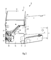
- shows the optical waveguide distribution device shown in
figure 1 in the partially open state, namely open at a front wall, with a partially broken-away side wall and with a patch panel pivoted into an operating position; - Figure 3
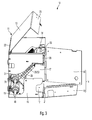
- shows the optical waveguide distribution device shown in
figure 2 in the completely open state, namely open at a front wall and a top wall, with a partially broken-away side wall; - Figure 4
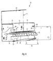
- shows the optical waveguide distribution device shown in
figure 3 with a patch panel pivoted into a service position; - Figure 5
- shows a cross section through the optical waveguide distribution device shown in
figure 1 ; - Figure 6
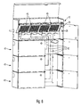
- shows the optical waveguide distribution device shown in
figure 1 together with three other optical waveguide distribution devices; and - Figure 7
- shows the optical waveguide distribution device shown in
figure 1 together with another optical waveguide distribution device. -
Figures 1 to 5 show different views and details of an opticalwaveguide distribution device 10 according to the invention. - The optical
waveguide distribution device 10 according to the invention has ahousing 11, thehousing 11 having alower base wall 12, anupper top wall 13, afront wall 14, arear wall 15 andside walls walls walls 12 to 17 of thehousing 11 of the opticalwaveguide distribution device 10 define an interior of thehousing 11. - In the exemplary embodiment shown, the
front wall 14 is designed to be divided and comprises adoor section 18, which is capable of being pivoted about a vertical axis, and adoor section 19, which is capable of being pivoted about a horizontal axis, ahinge 20 being associated with theside wall 17 for pivoting thefirst door section 18 about the vertical axis, and ahinge 21 being associated with thebase wall 12 for pivoting thesecond door section 19 about the horizontal axis. - The
upper top wall 13 of thehousing 10 is in the form of a cover which is capable of being pivoted about a horizontal axis, ahinge 22, about which thetop wall 13 is capable of being pivoted about the horizontal axis, being associated with therear wall 15 of thehousing 11. - The
top wall 13 is bent back on the side opposite thehinge 22, with asection 23 which is bent back on this side and is fixedly connected to thetop wall 13 being part of thefront wall 14 of thehousing 11 in the completely closed state of thehousing 11. - As can be seen from
figures 1 and5 , in the completely closed state of thehousing 11, the twodoor sections front wall 14 cover thesection 23 partially, with the result that thetop wall 13 of thehousing 11 can only be opened and pivoted about thehinge 22 when thedoor sections front wall 14 have already been opened. This region of overlap between thedoor sections section 23 is formed in the circledregion 24 infigure 5 . - In the interior of the
housing 11 of the opticalwaveguide distribution device 10, apatch panel 25, which bears a plurality ofadapters adapters - The
patch panel 25 divides the interior of thehousing 11 into a first interior region 28, which is accessible from thefront wall 14 of thehousing 11, and a secondinterior region 29, which is accessible from thetop wall 13 of thehousing 11. - A section 30, which bears the
adapters patch panel 25, said section being shown in an operating position of thepatch panel 25 infigures 2 ,3 and5 and in a service position of thepatch panel 25 infigure 4 , is set at an angle both with respect to the horizontally runningbase wall 12 and thetop wall 13 and with respect to the vertically runningrear wall 15 and thefront wall 14 in the operating position of thepatch panel 25, namely in such a way that, in the operating position of thepatch panel 25, theadapters 26 which are accessible from the first interior region 28 are directed downwards at an angle and theadapters 27 which are accessible from the secondinterior region 29 are directed upwards at an angle. When the twodoor sections front wall 14 are open, the first interior region 28 is accessible from thefront wall 14, with in this case theadapters 26 which protrude downwards at an angle into the first interior region 28 being accessible as well. - In order to access the
adapters 27 which protrude upwards at an angle into the secondinterior region 29, thetop wall 13 also needs to be pivoted and opened in order to thus provide access to the secondinterior region 29. - In order in this case to facilitate access to the
adapters 27 which protrude into the secondinterior region 29, thepatch panel 25 is capable of being pivoted about a horizontally running axis from the operating position shown infigures 2 ,3 and5 into the service position shown infigure 4 , and vice versa, with it being possible for this pivoting movement to be performed exclusively when thetop wall 13 is open. - In the service position (see
figure 4 ), that section 30 of thepatch panel 25 which bears theadapters base wall 12 of thehousing 11 of the opticalwaveguide distribution device 10. - In the operating position (see in particular
figure 5 ) of thepatch panel 25, that section 30 of said patch panel which bears theadapters base wall 12 through an angle of between 20 and 70°, in particular through an angle of between 35 and 55°, preferably through an angle of approximately 45°. - Such an angle firstly enables good accessibility of the
adapters 26 which are accessible from the first interior region 28 in the case of thepatch panel 25 assuming the operating position and secondly means that, when thepatch panel 25 is pivoted from the operating position into the service position, optical waveguides which are contact-connected to theadapters patch panel 25 via optical waveguide plugs are only subjected to low mechanical stress. - That section 30 of the
patch panel 25 which bears theadapters hinge 32 over asection 31 which is bent back downwards with respect to the section 30, with it being possible for thepatch panel 25 to be pivoted about saidhinge 32 about the horizontal axis between the operating position and the service position. In the exemplary embodiment shown, thesection 31 of thepatch panel 25 is bent back downwards through approximately 90° with respect to thesection 25 of said patch panel. - As can best be seen from
figure 5 , the horizontally runninghinge 32, about which thepatch panel 25 can be pivoted, is positioned above thebase wall 12. A vertical distance between thehinge 32 and thebase wall 12 is in this case preferably greater than a vertical distance between thehinge 32 and the lower side of that section 30 of thepatch panel 25 which bears the adapters. As a result, good accessibility of the adapters with low mechanical loading of the optical waveguides is ensured when the patch panel is pivoted. - That section 30 of the
patch panel 25 which bears theadapters side walls housing 11 over asection 33 which is bent back downwards with respect to this section 30, namely usingfastening elements 34 which are associated with theside walls figure 4 , pin-like protrusions 35 are formed on thesection 33 externally and adjacent to theside walls protrusions 35 protrude into cut-outs in inwardly protrudinglugs 36 of theside walls figure 3 ), and can then be fixed to thelugs 36 via thefastening elements 34. Only when thetop wall 13 is open is it possible to gain access to thefastening elements 34 and for thepatch panel 25 to be released from the operating position and therefore pivoted into the service position. - The
section 33, which is bent back with respect to that section 30 of thepatch panel 25 which bears the adapters on the upper side of said section 30 furthermore has, as can best be seen fromfigure 4 ,openings 37, into which optical waveguide holders can be inserted in order to manipulate optical waveguides in the interior of thehousing 11 which are guided in pigtails and are contact-connected to theadapters - Preferably, the optical
waveguide distribution device 10 is equipped or prefabricated at the factory end with pigtails inserted into therespective adapters 27 via optical waveguide plugs on theadapters 27 of thepatch panel 25 which are accessible from the secondinterior region 29. The optical waveguides of these pigtails, which are connected to theadapters 27 and are stored in the secondinterior region 29 of thehousing 11, are passed out of the secondinterior region 29, as can best be seen fromfigures 1 ,2 and3 , namely viaopenings 38, which are introduced into theside wall 16. Theseopenings 38 serve the purpose in particular of accommodating so-called furcation adapters in order to split optical waveguides which are inserted into the secondinterior region 29 of thehousing 11 via thecables figures 1 and2 into the individual pigtails. -
Figures 6 shows the opticalwaveguide distribution device 10 according to the invention together with three further opticalwaveguide distribution devices 41, which are combined to form a system, wherein in the arrangement shown infigure 6 , the opticalwaveguide distribution devices 41 are used as so-called provider distribution device and the opticalwaveguide distribution device 10 according to the invention is used as a so-called customer distribution device. Theprovider distributing devices 41 can be used to split optical waveguides which are guided in optical waveguide cables belonging to providers in the region of the opticalwaveguide distribution devices 41 and to supply said optical waveguides, in the direction of thepaths 42 shown schematically infigure 6 , to different sections 43 of thepatch panel 25 of thecustomer distribution device 10, namely to thoseadapters 26 of thepatch panel 25 which are accessible from the first interior region 28. - In this case, a provider-individual section 43 of the
patch panel 25 is associated with each provider. In the system shown infigure 6 , thepatch panel 25 comprises four provider-individual sections 43 for four different providers. By virtue of corresponding grouping and manipulation of the pigtails which are contact-connected to theadapters 27 of thepatch panel 25 starting from the secondinterior region 29, a group of four optical waveguides can thus be supplied from four different providers to each customer. - Mention is made of the fact that the system shown in
figure 6 , which serves to supply four fibres of four different providers in the direction of a customer, is purely exemplary in nature. It is of course also possible to choose a system in which two or three fibres or even more than four fibres of in each case different providers are supplied to each customer. -
Figure 7 shows the opticalwaveguide distribution device 10 according to the invention together with a further opticalwaveguide distribution device 41, whereinfigure 7 shows that anoptical waveguide 46 which is supplied to the customer opticalwaveguide distribution device 10 via a so-called provider opticalwaveguide distribution device 41, can also be guided past thepatch panel 25 and can be spliced directly so as to form asplice 44 with an optical waveguide of acable 45 leading to a customer. - List of Reference Symbols
- 10
- Optical waveguide distribution device
- 11
- Housing
- 12
- Base wall
- 13
- Top wall
- 14
- Front wall
- 15
- Rear wall
- 16
- Side wall
- 17
- Side wall
- 18
- Door section
- 19
- Door section
- 20
- Hinge
- 21
- Hinge
- 22
- Hinge
- 23
- Section
- 24
- Region
- 25
- Patch panel
- 26
- Adapter
- 27
- Adapter
- 28
- Interior region
- 29
- Interior region
- 30
- Section
- 31
- Section
- 32
- Hinge
- 33
- Section
- 34
- Fastening element
- 35
- Protrusion
- 36
- Lug
- 37
- Opening
- 38
- Opening
- 39
- Cable
- 40
- Cable
- 41
- Optical waveguide distribution device
- 42
- Path
- 43
- Section
- 44
- Cable
- 45
- Splice
- 46
- Optical waveguide
Claims (13)
- Optical waveguide distribution device, with a housing (11) and with assemblies accommodated in an interior of the housing (11) for connecting optical waveguides, the housing having a lower base wall (12), an upper top wall (13), a rear wall (15), a front wall (14) and side walls (16, 17) extending between the base wall, the top wall, the rear wall and the front wall, and adapters (26, 27), accommodated on a patch panel (25), for optical waveguide plugs being positioned as assemblies for connecting optical waveguides in the interior of the housing, characterized in that
the patch panel (25) divides the interior of the housing (11) into a first interior region (28), which is accessible from the front wall (14) of the housing, and a second interior region (29), which is accessible from the top wall (13) of the housing;
a section (30), which bears the adapters (26, 27), of the patch panel (25) in an operating position of the patch panel (25) is set at an angle both with respect to the horizontally running base wall and top wall and with respect to the vertically running rear wall and front wall, namely in such a way that, in the operating position of the patch panel (25), adapters (26) which are accessible from the first interior region (28) are directed downwards at an angle and adapters (27) which are accessible from the second interior region (29) are directed upwards at an angle;
the patch panel (25) is capable of being pivoted about a horizontally running axis between the operating position and a service position. - Optical waveguide distribution device according to Claim 1, characterized in that the front wall (14) has a first door section (18), which is capable of being pivoted about a vertical axis, and a second door section (19), which is capable of being pivoted about a horizontal axis.
- Optical waveguide distribution device according to Claim 1 or 2, characterized in that the top wall (13) forms a cover which is capable of being pivoted about a horizontal axis.
- Optical waveguide distribution device according to one of Claims 1 to 3, characterized in that the top wall (13) can be opened exclusively when the front wall (14) is open.
- Optical waveguide distribution device according to one of Claims 1 to 4, characterized in that the patch panel (25) is capable of being pivoted from the operating position into the service position and vice versa exclusively when the top wall (13) is open.
- Optical waveguide distribution device according to one of Claims 1 to 5, characterized in that the patch panel (25) is capable of being pivoted downwards about the horizontally running axis from the operating position into the service position in such a way that that section (30) of the patch panel (25) which bears the adapters runs approximately parallel to the base wall (12).
- Optical waveguide distribution device according to one of Claims 1 to 6, characterized in that that section (30) of the patch panel (25) which bears the adapters in the operating position of said patch panel is set at an angle with respect to the horizontally running base wall (12) through an angle of between 20° and 70°, in particular through an angle of between 35° and 55°, preferably through an angle of approximately 45°.
- Optical waveguide distribution device according to one of Claims 1 to 7, characterized in that that section (30) of the patch panel (25) which bears the adapters on a lower side of said patch panel acts on a horizontally running hinge (32) over a section (31) which is bent back downwards with respect to this section (30) through preferably approximately 90°.
- Optical waveguide distribution device according to Claim 8, characterized in that the horizontally running hinge (32) is arranged above the base wall (12).
- Optical waveguide distribution device according to Claim 8 or 9, characterized in that a vertical distance between the hinge (32) and the base wall (12) is greater than a vertical distance between the hinge (32) and the lower side of that section (30) of the patch panel (25) which bears the adapters.
- Optical waveguide distribution device according to one of Claims 1 to 10, characterized in that that section (30) of the patch panel (25) which bears the adapters, on an upper side of said patch panel, can be fixed in the operating position using fastening elements (34) associated with the side walls (15, 16) over a section (33) which is bent back downwards with respect to this section (30).
- Optical waveguide distribution device according to Claim 11, characterized in that the section (32) which is bent back on the upper side of that section (30) of the patch panel (25) which bears the adapters has openings (37) for accommodating optical waveguide holders.
- Optical waveguide distribution device according to one of Claims 1 to 12, characterized in that said optical waveguide distribution device is equipped with pigtails on the adapters (27) of the patch panel (25) which are accessible from the second interior region (29), said pigtails being inserted into the adapters (27) via optical waveguide plugs, and the optical waveguides of the pigtails being passed out of the housing (11) out of the second interior region (29) thereof via at least one opening (28) in a side wall (15) of the housing (11).
Applications Claiming Priority (1)
| Application Number | Priority Date | Filing Date | Title |
|---|---|---|---|
| DE202011002543U DE202011002543U1 (en) | 2011-02-09 | 2011-02-09 | Optical fiber distribution device |
Publications (1)
| Publication Number | Publication Date |
|---|---|
| EP2487517A1 true EP2487517A1 (en) | 2012-08-15 |
Family
ID=43993334
Family Applications (1)
| Application Number | Title | Priority Date | Filing Date |
|---|---|---|---|
| EP12153559A Withdrawn EP2487517A1 (en) | 2011-02-09 | 2012-02-02 | Optical waveguide distribution device |
Country Status (2)
| Country | Link |
|---|---|
| EP (1) | EP2487517A1 (en) |
| DE (1) | DE202011002543U1 (en) |
Citations (4)
| Publication number | Priority date | Publication date | Assignee | Title |
|---|---|---|---|---|
| US6385381B1 (en) * | 1999-09-21 | 2002-05-07 | Lucent Technologies Inc. | Fiber optic interconnection combination closure |
| WO2003102645A2 (en) * | 2002-05-31 | 2003-12-11 | Adc Telecommunications, Inc. | Optical fiber management module with cable storage spools |
| US20070189691A1 (en) * | 2006-02-13 | 2007-08-16 | Michael Barth | Fiber distribution hub with swing frame and modular termination panels |
| EP2060942A2 (en) | 2007-11-06 | 2009-05-20 | Corning Cable Systems Polska SP. zo.o. | Modular separating box for light guides and a system of modular separating boxes for light guides |
-
2011
- 2011-02-09 DE DE202011002543U patent/DE202011002543U1/en not_active Expired - Lifetime
-
2012
- 2012-02-02 EP EP12153559A patent/EP2487517A1/en not_active Withdrawn
Patent Citations (4)
| Publication number | Priority date | Publication date | Assignee | Title |
|---|---|---|---|---|
| US6385381B1 (en) * | 1999-09-21 | 2002-05-07 | Lucent Technologies Inc. | Fiber optic interconnection combination closure |
| WO2003102645A2 (en) * | 2002-05-31 | 2003-12-11 | Adc Telecommunications, Inc. | Optical fiber management module with cable storage spools |
| US20070189691A1 (en) * | 2006-02-13 | 2007-08-16 | Michael Barth | Fiber distribution hub with swing frame and modular termination panels |
| EP2060942A2 (en) | 2007-11-06 | 2009-05-20 | Corning Cable Systems Polska SP. zo.o. | Modular separating box for light guides and a system of modular separating boxes for light guides |
Also Published As
| Publication number | Publication date |
|---|---|
| DE202011002543U1 (en) | 2011-05-12 |
Similar Documents
| Publication | Publication Date | Title |
|---|---|---|
| US7496269B1 (en) | Fiber optic enclosure | |
| US10670821B2 (en) | Optical fiber organizer with trays mounted on pivoting support | |
| US9291790B2 (en) | Fiber splice enclosure having removable cable port mounting plate | |
| EP2191315B1 (en) | Modular system and methods for connecting an external communication network to a user network of a building | |
| US11467362B2 (en) | Telecommunications module and frame | |
| CN101263409B (en) | Boots and Organizers for Communications Lines and Connectors | |
| US20200124809A1 (en) | Fiber optic enclosure for retrofitting pedestals in the field | |
| EP2365364B1 (en) | Terminal enclosure with extractable fiber organizer tray | |
| US8886003B2 (en) | Integrated distribution enabling access apparatus | |
| AU2009212777A1 (en) | High-density patch-panel assemblies for optical fiber telecommunications | |
| EP2927724B1 (en) | Fiber optic distribution device | |
| CN100592122C (en) | Housings for communication lines and connectors | |
| EP4187301A1 (en) | Fiber-optic apparatus | |
| EP2315062A2 (en) | Pigtail handling device and optical waveguide distribution device | |
| EP2521234A1 (en) | Wall mounted plate with integrated ducts | |
| EP2490057B1 (en) | Support of an optical fibre organizer system with an optical coupler | |
| EP3465311B1 (en) | Telecommunications closure with point of connection plate holders | |
| US8260105B2 (en) | Enclosure for housing splice trays | |
| US20240142735A1 (en) | Fiber-optic apparatus | |
| EP4249976B1 (en) | Fiber routing insert and optical junction or distribution box | |
| US20250355208A1 (en) | Fiber optic apparatus with cable sealing arrangement | |
| FR3120265A3 (en) | FIBER OPTIC WALL SOCKET | |
| JP2008158340A (en) | Optical cable connection closure |
Legal Events
| Date | Code | Title | Description |
|---|---|---|---|
| PUAI | Public reference made under article 153(3) epc to a published international application that has entered the european phase |
Free format text: ORIGINAL CODE: 0009012 |
|
| AK | Designated contracting states |
Kind code of ref document: A1 Designated state(s): AL AT BE BG CH CY CZ DE DK EE ES FI FR GB GR HR HU IE IS IT LI LT LU LV MC MK MT NL NO PL PT RO RS SE SI SK SM TR |
|
| AX | Request for extension of the european patent |
Extension state: BA ME |
|
| STAA | Information on the status of an ep patent application or granted ep patent |
Free format text: STATUS: THE APPLICATION IS DEEMED TO BE WITHDRAWN |
|
| 18D | Application deemed to be withdrawn |
Effective date: 20130216 |