EP2485955B1 - Container portion for a carton with a plastic reclosable header - Google Patents
Container portion for a carton with a plastic reclosable header Download PDFInfo
- Publication number
- EP2485955B1 EP2485955B1 EP10822404.9A EP10822404A EP2485955B1 EP 2485955 B1 EP2485955 B1 EP 2485955B1 EP 10822404 A EP10822404 A EP 10822404A EP 2485955 B1 EP2485955 B1 EP 2485955B1
- Authority
- EP
- European Patent Office
- Prior art keywords
- zipper
- package
- header
- fold
- semi
- Prior art date
- Legal status (The legal status is an assumption and is not a legal conclusion. Google has not performed a legal analysis and makes no representation as to the accuracy of the status listed.)
- Not-in-force
Links
Images


Classifications
-
- B—PERFORMING OPERATIONS; TRANSPORTING
- B65—CONVEYING; PACKING; STORING; HANDLING THIN OR FILAMENTARY MATERIAL
- B65D—CONTAINERS FOR STORAGE OR TRANSPORT OF ARTICLES OR MATERIALS, e.g. BAGS, BARRELS, BOTTLES, BOXES, CANS, CARTONS, CRATES, DRUMS, JARS, TANKS, HOPPERS, FORWARDING CONTAINERS; ACCESSORIES, CLOSURES, OR FITTINGS THEREFOR; PACKAGING ELEMENTS; PACKAGES
- B65D5/00—Rigid or semi-rigid containers of polygonal cross-section, e.g. boxes, cartons or trays, formed by folding or erecting one or more blanks made of paper
- B65D5/02—Rigid or semi-rigid containers of polygonal cross-section, e.g. boxes, cartons or trays, formed by folding or erecting one or more blanks made of paper by folding or erecting a single blank to form a tubular body with or without subsequent folding operations, or the addition of separate elements, to close the ends of the body
- B65D5/08—Rigid or semi-rigid containers of polygonal cross-section, e.g. boxes, cartons or trays, formed by folding or erecting one or more blanks made of paper by folding or erecting a single blank to form a tubular body with or without subsequent folding operations, or the addition of separate elements, to close the ends of the body with end closures formed by inward-folding of portions of body, e.g. flaps, interconnected by, or incorporating, gusset folds
-
- B—PERFORMING OPERATIONS; TRANSPORTING
- B65—CONVEYING; PACKING; STORING; HANDLING THIN OR FILAMENTARY MATERIAL
- B65D—CONTAINERS FOR STORAGE OR TRANSPORT OF ARTICLES OR MATERIALS, e.g. BAGS, BARRELS, BOTTLES, BOXES, CANS, CARTONS, CRATES, DRUMS, JARS, TANKS, HOPPERS, FORWARDING CONTAINERS; ACCESSORIES, CLOSURES, OR FITTINGS THEREFOR; PACKAGING ELEMENTS; PACKAGES
- B65D33/00—Details of, or accessories for, sacks or bags
- B65D33/16—End- or aperture-closing arrangements or devices
- B65D33/25—Riveting; Dovetailing; Screwing; using press buttons or slide fasteners
- B65D33/2508—Riveting; Dovetailing; Screwing; using press buttons or slide fasteners using slide fasteners with interlocking members having a substantially uniform section throughout the length of the fastener; Sliders therefor
-
- B—PERFORMING OPERATIONS; TRANSPORTING
- B31—MAKING ARTICLES OF PAPER, CARDBOARD OR MATERIAL WORKED IN A MANNER ANALOGOUS TO PAPER; WORKING PAPER, CARDBOARD OR MATERIAL WORKED IN A MANNER ANALOGOUS TO PAPER
- B31B—MAKING CONTAINERS OF PAPER, CARDBOARD OR MATERIAL WORKED IN A MANNER ANALOGOUS TO PAPER
- B31B50/00—Making rigid or semi-rigid containers, e.g. boxes or cartons
- B31B50/26—Folding sheets, blanks or webs
-
- B—PERFORMING OPERATIONS; TRANSPORTING
- B65—CONVEYING; PACKING; STORING; HANDLING THIN OR FILAMENTARY MATERIAL
- B65D—CONTAINERS FOR STORAGE OR TRANSPORT OF ARTICLES OR MATERIALS, e.g. BAGS, BARRELS, BOTTLES, BOXES, CANS, CARTONS, CRATES, DRUMS, JARS, TANKS, HOPPERS, FORWARDING CONTAINERS; ACCESSORIES, CLOSURES, OR FITTINGS THEREFOR; PACKAGING ELEMENTS; PACKAGES
- B65D15/00—Containers having bodies formed by interconnecting or uniting two or more rigid, or substantially rigid, sections made of different materials
- B65D15/22—Containers having bodies formed by interconnecting or uniting two or more rigid, or substantially rigid, sections made of different materials of polygonal cross-section
-
- B—PERFORMING OPERATIONS; TRANSPORTING
- B65—CONVEYING; PACKING; STORING; HANDLING THIN OR FILAMENTARY MATERIAL
- B65D—CONTAINERS FOR STORAGE OR TRANSPORT OF ARTICLES OR MATERIALS, e.g. BAGS, BARRELS, BOTTLES, BOXES, CANS, CARTONS, CRATES, DRUMS, JARS, TANKS, HOPPERS, FORWARDING CONTAINERS; ACCESSORIES, CLOSURES, OR FITTINGS THEREFOR; PACKAGING ELEMENTS; PACKAGES
- B65D33/00—Details of, or accessories for, sacks or bags
- B65D33/16—End- or aperture-closing arrangements or devices
- B65D33/25—Riveting; Dovetailing; Screwing; using press buttons or slide fasteners
- B65D33/2508—Riveting; Dovetailing; Screwing; using press buttons or slide fasteners using slide fasteners with interlocking members having a substantially uniform section throughout the length of the fastener; Sliders therefor
- B65D33/2516—Riveting; Dovetailing; Screwing; using press buttons or slide fasteners using slide fasteners with interlocking members having a substantially uniform section throughout the length of the fastener; Sliders therefor comprising tamper-indicating means, e.g. located within the fastener
-
- B—PERFORMING OPERATIONS; TRANSPORTING
- B65—CONVEYING; PACKING; STORING; HANDLING THIN OR FILAMENTARY MATERIAL
- B65D—CONTAINERS FOR STORAGE OR TRANSPORT OF ARTICLES OR MATERIALS, e.g. BAGS, BARRELS, BOTTLES, BOXES, CANS, CARTONS, CRATES, DRUMS, JARS, TANKS, HOPPERS, FORWARDING CONTAINERS; ACCESSORIES, CLOSURES, OR FITTINGS THEREFOR; PACKAGING ELEMENTS; PACKAGES
- B65D33/00—Details of, or accessories for, sacks or bags
- B65D33/16—End- or aperture-closing arrangements or devices
- B65D33/25—Riveting; Dovetailing; Screwing; using press buttons or slide fasteners
- B65D33/2508—Riveting; Dovetailing; Screwing; using press buttons or slide fasteners using slide fasteners with interlocking members having a substantially uniform section throughout the length of the fastener; Sliders therefor
- B65D33/2541—Riveting; Dovetailing; Screwing; using press buttons or slide fasteners using slide fasteners with interlocking members having a substantially uniform section throughout the length of the fastener; Sliders therefor characterised by the slide fastener, e.g. adapted to interlock with a sheet between the interlocking members having sections of particular shape
-
- B—PERFORMING OPERATIONS; TRANSPORTING
- B65—CONVEYING; PACKING; STORING; HANDLING THIN OR FILAMENTARY MATERIAL
- B65D—CONTAINERS FOR STORAGE OR TRANSPORT OF ARTICLES OR MATERIALS, e.g. BAGS, BARRELS, BOTTLES, BOXES, CANS, CARTONS, CRATES, DRUMS, JARS, TANKS, HOPPERS, FORWARDING CONTAINERS; ACCESSORIES, CLOSURES, OR FITTINGS THEREFOR; PACKAGING ELEMENTS; PACKAGES
- B65D5/00—Rigid or semi-rigid containers of polygonal cross-section, e.g. boxes, cartons or trays, formed by folding or erecting one or more blanks made of paper
- B65D5/02—Rigid or semi-rigid containers of polygonal cross-section, e.g. boxes, cartons or trays, formed by folding or erecting one or more blanks made of paper by folding or erecting a single blank to form a tubular body with or without subsequent folding operations, or the addition of separate elements, to close the ends of the body
- B65D5/06—Rigid or semi-rigid containers of polygonal cross-section, e.g. boxes, cartons or trays, formed by folding or erecting one or more blanks made of paper by folding or erecting a single blank to form a tubular body with or without subsequent folding operations, or the addition of separate elements, to close the ends of the body with end-closing or contents-supporting elements formed by folding inwardly a wall extending from, and continuously around, an end of the tubular body
- B65D5/064—Rectangular containers having a body with gusset-flaps folded outwardly or adhered to the side or the top of the container
-
- B—PERFORMING OPERATIONS; TRANSPORTING
- B65—CONVEYING; PACKING; STORING; HANDLING THIN OR FILAMENTARY MATERIAL
- B65D—CONTAINERS FOR STORAGE OR TRANSPORT OF ARTICLES OR MATERIALS, e.g. BAGS, BARRELS, BOTTLES, BOXES, CANS, CARTONS, CRATES, DRUMS, JARS, TANKS, HOPPERS, FORWARDING CONTAINERS; ACCESSORIES, CLOSURES, OR FITTINGS THEREFOR; PACKAGING ELEMENTS; PACKAGES
- B65D5/00—Rigid or semi-rigid containers of polygonal cross-section, e.g. boxes, cartons or trays, formed by folding or erecting one or more blanks made of paper
- B65D5/02—Rigid or semi-rigid containers of polygonal cross-section, e.g. boxes, cartons or trays, formed by folding or erecting one or more blanks made of paper by folding or erecting a single blank to form a tubular body with or without subsequent folding operations, or the addition of separate elements, to close the ends of the body
- B65D5/12—Rigid or semi-rigid containers of polygonal cross-section, e.g. boxes, cartons or trays, formed by folding or erecting one or more blanks made of paper by folding or erecting a single blank to form a tubular body with or without subsequent folding operations, or the addition of separate elements, to close the ends of the body with end closures formed separately from tubular body
-
- B—PERFORMING OPERATIONS; TRANSPORTING
- B65—CONVEYING; PACKING; STORING; HANDLING THIN OR FILAMENTARY MATERIAL
- B65D—CONTAINERS FOR STORAGE OR TRANSPORT OF ARTICLES OR MATERIALS, e.g. BAGS, BARRELS, BOTTLES, BOXES, CANS, CARTONS, CRATES, DRUMS, JARS, TANKS, HOPPERS, FORWARDING CONTAINERS; ACCESSORIES, CLOSURES, OR FITTINGS THEREFOR; PACKAGING ELEMENTS; PACKAGES
- B65D5/00—Rigid or semi-rigid containers of polygonal cross-section, e.g. boxes, cartons or trays, formed by folding or erecting one or more blanks made of paper
- B65D5/42—Details of containers or of foldable or erectable container blanks
- B65D5/4266—Folding lines, score lines, crease lines
-
- B—PERFORMING OPERATIONS; TRANSPORTING
- B65—CONVEYING; PACKING; STORING; HANDLING THIN OR FILAMENTARY MATERIAL
- B65D—CONTAINERS FOR STORAGE OR TRANSPORT OF ARTICLES OR MATERIALS, e.g. BAGS, BARRELS, BOTTLES, BOXES, CANS, CARTONS, CRATES, DRUMS, JARS, TANKS, HOPPERS, FORWARDING CONTAINERS; ACCESSORIES, CLOSURES, OR FITTINGS THEREFOR; PACKAGING ELEMENTS; PACKAGES
- B65D5/00—Rigid or semi-rigid containers of polygonal cross-section, e.g. boxes, cartons or trays, formed by folding or erecting one or more blanks made of paper
- B65D5/42—Details of containers or of foldable or erectable container blanks
- B65D5/4279—Joints, seams, leakproof joints or corners, special connections between panels
-
- B—PERFORMING OPERATIONS; TRANSPORTING
- B65—CONVEYING; PACKING; STORING; HANDLING THIN OR FILAMENTARY MATERIAL
- B65D—CONTAINERS FOR STORAGE OR TRANSPORT OF ARTICLES OR MATERIALS, e.g. BAGS, BARRELS, BOTTLES, BOXES, CANS, CARTONS, CRATES, DRUMS, JARS, TANKS, HOPPERS, FORWARDING CONTAINERS; ACCESSORIES, CLOSURES, OR FITTINGS THEREFOR; PACKAGING ELEMENTS; PACKAGES
- B65D5/00—Rigid or semi-rigid containers of polygonal cross-section, e.g. boxes, cartons or trays, formed by folding or erecting one or more blanks made of paper
- B65D5/42—Details of containers or of foldable or erectable container blanks
- B65D5/56—Linings or internal coatings, e.g. pre-formed trays provided with a blow- or thermoformed layer
- B65D5/60—Loose, or loosely attached, linings
- B65D5/603—Flexible linings loosely glued to the wall of the container
- B65D5/606—Bags or bag-like tubes loosely glued to the wall of a "tubular" container
-
- B—PERFORMING OPERATIONS; TRANSPORTING
- B65—CONVEYING; PACKING; STORING; HANDLING THIN OR FILAMENTARY MATERIAL
- B65D—CONTAINERS FOR STORAGE OR TRANSPORT OF ARTICLES OR MATERIALS, e.g. BAGS, BARRELS, BOTTLES, BOXES, CANS, CARTONS, CRATES, DRUMS, JARS, TANKS, HOPPERS, FORWARDING CONTAINERS; ACCESSORIES, CLOSURES, OR FITTINGS THEREFOR; PACKAGING ELEMENTS; PACKAGES
- B65D75/00—Packages comprising articles or materials partially or wholly enclosed in strips, sheets, blanks, tubes, or webs of flexible sheet material, e.g. in folded wrappers
- B65D75/52—Details
- B65D75/58—Opening or contents-removing devices added or incorporated during package manufacture
-
- B—PERFORMING OPERATIONS; TRANSPORTING
- B31—MAKING ARTICLES OF PAPER, CARDBOARD OR MATERIAL WORKED IN A MANNER ANALOGOUS TO PAPER; WORKING PAPER, CARDBOARD OR MATERIAL WORKED IN A MANNER ANALOGOUS TO PAPER
- B31B—MAKING CONTAINERS OF PAPER, CARDBOARD OR MATERIAL WORKED IN A MANNER ANALOGOUS TO PAPER
- B31B2105/00—Rigid or semi-rigid containers made by assembling separate sheets, blanks or webs
-
- B—PERFORMING OPERATIONS; TRANSPORTING
- B31—MAKING ARTICLES OF PAPER, CARDBOARD OR MATERIAL WORKED IN A MANNER ANALOGOUS TO PAPER; WORKING PAPER, CARDBOARD OR MATERIAL WORKED IN A MANNER ANALOGOUS TO PAPER
- B31B—MAKING CONTAINERS OF PAPER, CARDBOARD OR MATERIAL WORKED IN A MANNER ANALOGOUS TO PAPER
- B31B2120/00—Construction of rigid or semi-rigid containers
- B31B2120/30—Construction of rigid or semi-rigid containers collapsible; temporarily collapsed during manufacturing
-
- B—PERFORMING OPERATIONS; TRANSPORTING
- B31—MAKING ARTICLES OF PAPER, CARDBOARD OR MATERIAL WORKED IN A MANNER ANALOGOUS TO PAPER; WORKING PAPER, CARDBOARD OR MATERIAL WORKED IN A MANNER ANALOGOUS TO PAPER
- B31B—MAKING CONTAINERS OF PAPER, CARDBOARD OR MATERIAL WORKED IN A MANNER ANALOGOUS TO PAPER
- B31B50/00—Making rigid or semi-rigid containers, e.g. boxes or cartons
- B31B50/004—Closing boxes
- B31B50/0044—Closing boxes the boxes having their opening facing upwardly
-
- B—PERFORMING OPERATIONS; TRANSPORTING
- B31—MAKING ARTICLES OF PAPER, CARDBOARD OR MATERIAL WORKED IN A MANNER ANALOGOUS TO PAPER; WORKING PAPER, CARDBOARD OR MATERIAL WORKED IN A MANNER ANALOGOUS TO PAPER
- B31B—MAKING CONTAINERS OF PAPER, CARDBOARD OR MATERIAL WORKED IN A MANNER ANALOGOUS TO PAPER
- B31B50/00—Making rigid or semi-rigid containers, e.g. boxes or cartons
- B31B50/60—Uniting opposed surfaces or edges; Taping
- B31B50/64—Uniting opposed surfaces or edges; Taping by applying heat or pressure, e.g. by welding
-
- B—PERFORMING OPERATIONS; TRANSPORTING
- B31—MAKING ARTICLES OF PAPER, CARDBOARD OR MATERIAL WORKED IN A MANNER ANALOGOUS TO PAPER; WORKING PAPER, CARDBOARD OR MATERIAL WORKED IN A MANNER ANALOGOUS TO PAPER
- B31B—MAKING CONTAINERS OF PAPER, CARDBOARD OR MATERIAL WORKED IN A MANNER ANALOGOUS TO PAPER
- B31B50/00—Making rigid or semi-rigid containers, e.g. boxes or cartons
- B31B50/74—Auxiliary operations
- B31B50/81—Forming or attaching accessories, e.g. opening devices, closures or tear strings
- B31B50/814—Applying closure elements to blanks, webs or boxes
- B31B50/8144—Applying hook-and-loop-type fasteners
-
- B—PERFORMING OPERATIONS; TRANSPORTING
- B31—MAKING ARTICLES OF PAPER, CARDBOARD OR MATERIAL WORKED IN A MANNER ANALOGOUS TO PAPER; WORKING PAPER, CARDBOARD OR MATERIAL WORKED IN A MANNER ANALOGOUS TO PAPER
- B31B—MAKING CONTAINERS OF PAPER, CARDBOARD OR MATERIAL WORKED IN A MANNER ANALOGOUS TO PAPER
- B31B50/00—Making rigid or semi-rigid containers, e.g. boxes or cartons
- B31B50/74—Auxiliary operations
- B31B50/81—Forming or attaching accessories, e.g. opening devices, closures or tear strings
- B31B50/86—Forming integral handles; Attaching separate handles
- B31B50/87—Fitting separate handles on boxes, e.g. on drinking cups
-
- B—PERFORMING OPERATIONS; TRANSPORTING
- B65—CONVEYING; PACKING; STORING; HANDLING THIN OR FILAMENTARY MATERIAL
- B65D—CONTAINERS FOR STORAGE OR TRANSPORT OF ARTICLES OR MATERIALS, e.g. BAGS, BARRELS, BOTTLES, BOXES, CANS, CARTONS, CRATES, DRUMS, JARS, TANKS, HOPPERS, FORWARDING CONTAINERS; ACCESSORIES, CLOSURES, OR FITTINGS THEREFOR; PACKAGING ELEMENTS; PACKAGES
- B65D65/00—Wrappers or flexible covers; Packaging materials of special type or form
- B65D65/38—Packaging materials of special type or form
- B65D65/46—Applications of disintegrable, dissolvable or edible materials
- B65D65/466—Bio- or photodegradable packaging materials
Definitions
- the present disclosure relates to a container portion for producing a package with a carton-type container made from paper, cardboard, chipboard or similar rigid or semi-rigid material with attached thereto a reclosable header section made from plastic, polymer or other flexible material, the reclosable structure being typically a zipper, but not limited thereto.
- the present disclosure likewise relates to the resulting package.
- a package along with a method and apparatus for the production thereof, which includes a rigid or semi-rigid carton-type container and, attached thereto, a plastic, polymer, or similar flexible header, typically with a reclosable zipper configuration, but not limited thereto.
- the invention provides a container portion for a carton, comprising:
- the container portion may further include:
- An angle between a projection of the first and second rear interior vertical folds and the respective first and second rear inclined fold portions may be in the range of 1 -4 degrees.
- An angle between a projection of the first and second rear interior vertical folds and the respective first and second rear inclined fold portions may be in the range of 2-3 degrees.
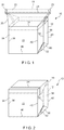
- Figure 1 is a perspective view of a package 10 of the present disclosure.
- Package 10 includes a rigid, semi-rigid or fibrous carton-type container 12, typically with a central layer 164 ( Figure 3B ) made from a paper product such as fiberboard or chipboard and an interior surface 166 with an oxygen barrier and a moisture barrier and a poly-coated outer layer 162, but is not limited thereto (hereinafter, collectively referred to as a "semi-rigid container”).
- Semi-rigid container 12 is typically initially provided in a flat configuration as shown in Figure 3A with an open top or mouth 14 and an open bottom 16.
- Package 10 further includes a plastic or polymeric header 18 (typically applied by heat, adhesive or glue) which includes first and second sidewalls 20, 22 and a reclosure (or closure) 24, illustrated as a zipper with first and second interlocking profiles 25, 27 (see Figure 6B ), but is not limited thereto.
- a plastic or polymeric header 18 typically applied by heat, adhesive or glue
- first and second sidewalls 20, 22 and a reclosure (or closure) 24, illustrated as a zipper with first and second interlocking profiles 25, 27 (see Figure 6B ), but is not limited thereto.
- reclosures include, but are not limited to, flanged zippers with opening lips, flanged tamper-resistant zippers, tamper-evident zippers, flanged zippers with sliders (see Figure 23 ), flanged zippers without sliders, string (flangeless) zippers, double zippers (see Figure 27I ), multiple track zippers, zippers with a tear line, a zipper with flanges connected above the locking elements, zippers with flanges connected below the locking elements, leak-resistant zippers, zippers with a peel seal, hinged zippers, zippers with spot seals, zippers with eyemarks, partly sealed zippers, zippers with shape-retaining characteristics, pinch grip pull zippers (i.e., lower product side opening strength than consumer side opening strength), zipper tape (especially for applications involving frozen foods), hook-and-eye (i.e., Velcro®), reclosable adhesives, perforated cap zipper tape, laminated zipper tape with a tear bead, zippers with
- header 18 examples include, but are not limited to, film with eyemarks, printed film (see Figure 22 ), film with cut-outs, film with diagonal seals and film with tear-lines.
- the header 18 is sealed or glued to the mouth 14 of semi-rigid container 12.
- First and second cross-seals 21, 23 or other methods of attachment are formed at the ends of header 18 between the sidewalls 20, 22, immediately outwardly adjacent from first and second folded edges (or first and second exterior folds) 30, 32.
- the first and second cross-seals 21, 23 further typically include respective first and second side incisions or notches 31, 33 in order to remove material to aid in the subsequent folding of the header 18 into the position shown in Figure 2 .
- Other shapes, such as single or multiple radius cut-outs are also envisioned. It is noted that it is envisioned that some applications may fold the header 18 onto the top of the package 10. However, it will be preferred in many applications that the reclosure or zipper 24 not be bent 180 degrees.
- the header 18 may be made with bio-degradable plastic. Additionally, in such an embodiment, the sealant for semi-rigid container 12 would also be made bio-degradable.
- semi-rigid container 12 is typically initially provided in a flat state with front panel 13 and rear panel 15.
- Semi-rigid container 12 is typically partially or fully poly-coated on exterior surface 162 ( Figure 3B ), particularly in the areas where heat sealing is required, such as the top of semi-rigid container 12 where header 18 is attached, and the portions of semi-rigid container 12 where the bottom is sealed shut before or after filling.
- adhesive is applied in the required areas and the attachment is done by these adhesives.
- interior coating or lamination may include other materials required for the necessary barrier properties, including hermeticity and oxygen-moisture barriers.
- front and rear panels 13, 15 typically have printing including advertising and product information in text and graphics form on the exterior thereof, such as most products commonly found in a grocery store or other retail establishment.
- Front panel 13 and rear panel 15 are joined to each other by first and second folded edges 30, 32 which ultimately become the central folds of the first and second gusseted sides 34, 36 of semi-rigid container 12 in the expanded or filled configuration as shown in Figures 1 and 2 .
- Front panel 13 of semi-rigid container 12 further includes first and second front interior vertical folds 38, 40 which are inwardly adjacent from and parallel to first and second folded edges 30, 32.
- first and second front interior vertical folds 38, 40 form the transition from the front surface 42 to the gusseted sides 34, 36.
- Similar first and second rear interior vertical folds 38', 40' are formed on the rear of the semi-rigid container 12, see Figures 5A and 5B , forming the transition from the rear surface 43 to the gusseted sides 34, 36.
- the upper ends of vertical folds 38, 38', 40, 40' may terminate in chamfered sections 39, 39', 41, 41', respectively, in order to prevent cracking of the material of semi-rigid container 12 during folding and further to reduce the likelihood of the material of semi-rigid container 12 forming a point to puncture the material of header 18.
- extra dots of glue indicated as "G" are provided at the top of first and second folded edges 30, 32 within first and second gusseted sides 34, 36.
- semi-rigid container 12 is typically formed from a single sheet of material with a seam 35 formed at the overlapping joinder of the edges (shown in Figure 7 as occurring at second interior vertical fold 40) an extra dot of glue (indicated as "G' ”) is provided at the top of seam 35 in order to prevent leakage between the semi-rigid container 12 and the header 18 due to the transition in thickness caused by seam 35.
- G' extra dot of glue
- Other embodiments may use an even number (four or greater) of panels.
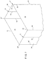
- first and second interior horizontal folds 46, 48 are formed on front panel 13 adjacent to the bottom 16. Similar first interior horizontal fold 46' is formed on the rear panel 15 of semi-rigid container 12, see Figures 5A, 5B . The first interior horizontal folds 46, 46' are used to form the transition to the bottom surface 50 while the second interior horizontal fold 48 is used to form the fin seal 52 as shown in Figures 4A, 4B , 5A and 5B .
- a second horizontal fold is not illustrated on the rear panel 15, as typically, only one of panels 13, 15 include a second horizontal fold in order to help force the fin seal 52 to fold in a specific direction.
- first and second front interior vertical folds 38, 40 form respective first and second inwardly inclined fold portions 139, 141.
- an angle of typically 1-4 degrees, or preferably 2-3 degrees in most applications is formed between the projection of respective front interior vertical folds 38, 40 (with substantially identical construction on the rear of semi-rigid container 12) and inwardly inclined fold portions 139, 141, so that the inwardly inclined fold portions 139, 141 incline or veer toward the center of the semi-rigid container 12 as the inwardly inclined fold portions 139, 141 approach the open bottom 16. This aids in the subsequent folding of the semi-rigid container 12 into the package 10.
- first and second oval-shaped partially scored portions 47, 49 are formed with a vertical major axis on semi-rigid container 12 immediately below header 18, outwardly adjacent from first and second front interior vertical folds 38, 40 (thereby being located within the gusseted sides after the package 10 has been formed).
- first and second oval-shaped dots of glue 51, 53 are placed on one side of front of header 18, typically above reclosure or zipper 24 and inwardly adjacent from respective first and second cross-seals 21, 23. Additionally, a dot of glue 55 may be placed just below the mid-point of the top edge of header 18. Typically, hot melt glue is used, but other glues or adhesives may be applicable to various applications.
- first and second oval-shaped dots of glue 51, 53 cover and are glued or otherwise secured to respective first and second oval-shaped partially scored portions 47, 49.
- dot of glue 55 tacks the top edge of header 18 against the folded-down sidewall 20.
- First and second oval-shaped partially scored portion 47, 49 are typically provided only on the front of semi-rigid container 12. Otherwise, the front and rear views of semi-rigid container 12 are substantially identical. Alternately, releasable configurations may be used to attach the folded header to the sides of the formed semi-rigid container, such as, but not limited to, releasable adhesives, hook-and-eye (Velcro®), multiple strips, etc.
- First diagonal fold 54 extends from the intersection of first interior vertical fold 38 and first horizontal fold 46 to the intersection of first folded edge 30 and second horizontal fold 48.
- second diagonal fold 56 extends from the intersection of second interior vertical fold 40 and first horizontal fold 46 to the intersection of second folded edge 32 and second horizontal fold 48.
- the lower corners are removed by first and second lower cuts 57, 59 which extend diagonally from the respective ends of second horizontal fold 48 to opposite ends of the bottom 16 of the semi-rigid container 12. This results in diagonal ends on fin seal 52 as shown in Figure 4A .
- similar first and second diagonal folds 54', 56' are formed on the rear panel 15 of semi-rigid container 12.
- first and second diagonal folds 54, 54', 56, 56' are necessary for forming the diagonal edges of first and second lower triangular ears 58, 60, shown in the transitory extended position in Figures 4A, 4B , 5A, 5B and shown in the final sealed flush position in Figures 1, 2 , 6A and 6B .
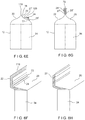
- Figures 6E and 6F illustrate a further package 10, wherein first and second sidewalls 20, 22 may be provided as two separate sheets or a single sheet, and wherein seal 119 either joins the two separate sheets or is formed in a central location on the single sheet.
- Sidewall 20 includes a line of weakness 72 (which may include perforations, laser scored lines, tear beads, tear notches, linear tear lines, a peel seal, or similar structures, and may be configured as multiple lines) with first and second flanges 25', 27' of zipper 24 extending over line of weakness 72 and sealed to first sidewall 20 on opposite sides of line of weakness 72.
- Zipper 24 further includes an opening zipper flange 123 extending therefrom. In this position, the zipper 24 is placed on the front of the header 18, in an off-central rather than central position.
- a similar alternative embodiment would attach the zipper 24 on the interior of first side wall 20.
- FIGS 6G and 6H illustrate a still further package 10 wherein the sidewalls 20, 22 are provided as separate sheets (or alternately, as a single sheet with an opening or tear line therethrough) and flanged zipper 24 with slider 70 is sealed to the exterior thereof (first flange 25' sealed to sidewall 20 and a second flange 27' sealed to sidewall 22) thereby allowing the consumer to operate the slider 70 to open the zipper 24 and thereby gain access to the contents of the package 10.
- Figures 8A-14 illustrate methods and apparatus for producing the packages 10 of Figures 1-7 .
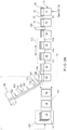
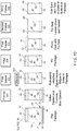
- Figures 8A-G and 9A-C illustrate methods and apparatus for producing the unfilled flat packages of Figure 3A .
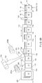
- a stack 11 of pre-made or previously made folded semi-rigid containers 12 is provided to a sequential feeder 290 (other sequential feeding apparatus, such as an upstream conveyor or pick-and-place apparatus, may be substituted for the stack 11 and sequential feeder 290), and the semi-rigid containers 12 are fed sequentially in a machine direction by a servo-driven conveyor 103.
- Web material 102 is provided from a spool 100, with periodic eyemarks 104 (in some applications, cut-outs in the web material could be substituted for eyemarks), the detection of which by eye-mark detector 111 is used to time the sequential feeding of semi-rigid containers 112 by sequential feeder 290 to conveyor 103 (the registration provided by the eyemarks 104 and the detection thereof is typically only required if the web material 102 has graphics or other printing with defined locations for the beginning and end of adjacent headers, see Figure 22 ).
- the detection of the periodic eyemarks 104 can be used to vary the speed of the conveyor 103 so that the semi-rigid containers are delivered with the correct registration with respect to the web material 102.
- Length of zipper material 202 is provided from spool 200 and is sealed to length of web material 102 at sealing and folding station 106 (length of zipper material 202 may be configured without sliders, with pre-mounted sliders, or with sliders mounted by optional slider mounting station 204 shortly after the zipper is provided from spool 200 or mounting station 204' can be located after the zipper material is attached to the web material as shown in Figure 8A ).
- This sealing may be done by attaching a first flange of an interlocked zipper material 202 to unfolded web material 102 and then attaching the second flange after the web material 102 is folded around the zipper material 202.
- the separate, unlocked profiles of zipper material 202 may be attached to the web material 102 and the web material 102 thereafter folded so that the profiles of zipper material 202 are aligned and interlocked (see the alternative illustrated in phantom in Figure 8B ).
- the interlocked zipper material 202 may be introduced between a folded web material 102 and then sealed or attached thereto.
- the zipper is attached to separate web materials. In such a method the zipper is either attached to one web in an unlocked condition, one section to each web, and thereafter, the zipper is aligned and interlocked or one side of an interlocked zipper material can be attached to one web material. Then the other web material can be attached to the other side of the zipper material.
- the zipper can be separated at a later stage for filling the semi-rigid container through the zipper. Additionally, while the preferred method of attaching together the zipper, web, and semi-rigid containers requires several steps, this may be done in fewer steps or even simultaneously.
- releasable dots of glue are applied to the length of web material at glue station 107 for the purpose of attaching the header 18 to the outside of formed semi-rigid container 12.
- glue station 107 the length of web 102 (with the zipper 202 attached thereto) is folded (the lateral edges of which thereby form first and second sidewalls 20, 22 of header 18 of Figures 1-6 ) so as to contact semi-rigid containers 12.
- the lateral edges of web material 102 are glued, sealed or otherwise fastened to front and rear panels 13, 15 of semi-rigid container 12 by web sealing or attaching station 108.
- Sealing station 108 typically includes compression rollers and a heated bar on both sides of the web.
- the sealing station may include multiple heated seal bars, wherein the semi-rigid container 12, with the header 18 in position, passes through these heated bars with little to no contact pressure. After each set of seal bars, the container 12 and header 18 pass through compression rollers.
- the compression rollers set the film-to-film seal (i.e., cross-seals 21, 23) between the semi-rigid containers 12 and the film-to-container seal over the containers 12. These compression rollers can be free-spinning or driven. Additionally, it has been found that by pre-tensioning the film of header 18 during sealing, that the package 10 becomes more rigid.
- the semi-rigid containers 12 with the web material 102 attached (with the zipper material 202, in turn, attached to web material 102) move in the machine direction.
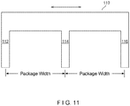
- a cross-sealer 110 with typically three cross-seal bars 112, 114, 116 reciprocates so that it momentarily travels in the machine direction, tracking the movement of the semi-rigid containers 12 and the web material 102 (with zipper material 202 attached thereto), and engages the web material 102 so that a first cross-seal 21 and adjoining second cross-seal 23 of an adjacent package are simultaneously formed in three successive inter-package gaps, typically without the necessity of slowing or stopping the travel of web material 102.
- the use of multiple cross-seal bars typically ultrasonic, but may include heat welding
- the synchronized travel with the web material 102 allows for a prolonged dwell time, thereby improving sealing qualities, while maintaining high production rates.
- a lesser or greater number of cross-seal bars may be implemented.
- the cross-sealer 110 then travels in the opposite direction from the machine direction to position itself for the cross-sealing operation with the successive or consecutive three inter-package gaps.
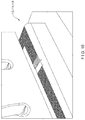
- the cross-seal bars 112, 114, 116 typically include a reverse knurled ultrasonic horn and a reverse knurled ultrasonic anvil as shown in Figure 10 .
- the reverse knurled surface creates a multitude of small pockets for the polymeric or similar material to flow during the sealing or welding of the cross-seals 21, 23. This produces high quality and aesthetically appealing cross-seals in half the time of heat and pressure sealing.
- FIGs 8A-G and 9A-C illustrate method and apparatus of attaching zipper web material to the outside of folded semi-rigid containers 12.
- zipper material can be attached to the inside of the semi-rigid containers 12.
- the edges 30, 32 of gussets 34, 36 are slit a required distance, and the zipper web material is introduced between the separated upper portions of gussets 34, 36 and attached thereto and to panels 13, 15.
- panels 13, 15 are provided with upwardly facing flaps 13', 15' between and to the inside of which zipper web material forming header 18 is attached as in Figure 3C .
- the web material 102 in the inter-package gaps is then severed by cutting station 120, resulting in the flat and unfilled packages 10 of Figure 3A .
- perforations can be made in the cross-seals by station 120, thereby leaving the packages in a concatenated chain.
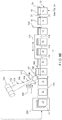
- Figure 8B shows a similar method and apparatus, wherein no eyemarks are provided on the web material 102 (typically because no graphics are provided on the web material 102 which would require critical registration) and wherein the conveyor 103 is a servo-driven chain with periodically spaced adjustable lugs 105 for engaging the trailing edges of semi-rigid containers 12 thereby assuring accurate spacing of the semi-rigid containers 12.
- a second source of zipper material 200B is a second source of zipper material 200B, wherein source 200 would include a first interlockable profile and source 200B would include a second interlockable profile.
- the separate, unlocked profiles of zipper material 202 may be attached to the web material 102 and the web material 102 thereafter folded so that the profiles of zipper material 202 are aligned and interlocked
- FIG. 8C another alternative is to provide two separate sheets of web 102A, 102B.
- Zipper profiles 202A, 202B are supplied from respective spools 200A, 200B and sealed to sheets of web 102A, 102B by sealing stations 106A, 106B.
- the zipper profiles 202A and 202B are then aligned and joined together and the top edges of the sheet web 102A, 102B sealed together at a joining and sealing station 109.
- the top edges 102A and 102B are left unsealed.
- FIG. 8D another alternative is to feed two sheets of web 102A, 102B and interlocked zipper 202 to sealing station 106 wherein a first profile of zipper 202 is sealed to web 102A and a second profile is sealed to web 102B simultaneously or at a later station.
- a first profile of zipper 202 is sealed to web 102A
- a second profile is sealed to web 102B simultaneously or at a later station.
- the top edges 102A, 102B are left unsealed.
- the top edges of sheets of web 102A, 102B are then sealed together at sealing station 109.
- Figure 27H is a representative cross section of what may be produced by this method and apparatus, showing, in particular, lines of weakness 72 or similar opening structure (which may include perforations, laser scored lines, tear beads, tear notches, linear tear lines, a peel seal, or similar structures, and may be configured as multiple lines) formed in sidewalls 20, 22 thereby providing access to zipper 24 after removal of removable header portion 29. Further illustrated in Figure 27H is pocket 133 formed between seals 135, 137 that can hold printed advertising or similar material 138 therein. This structure is likewise illustrated in Figure 22 .
- lines of weakness 72 or similar opening structure which may include perforations, laser scored lines, tear beads, tear notches, linear tear lines, a peel seal, or similar structures, and may be configured as multiple lines
- pocket 133 formed between seals 135, 137 that can hold printed advertising or similar material 138 therein. This structure is likewise illustrated in Figure 22 .
- segments of zipper material may be fed to the length of web material 102 by zipper feeder 206 as shown in Figure 17B resulting in a spaced-apart configuration. This may avoid having the zipper profile in cross-seals 21, 23, but requires accurate registration of the zippers 24 with respect to the web material 102.
- the zipper segments may be applied to web material 102 in line with the web direction or at an angle to it.
- stack 11 is implemented as a magazine with containers 12 stacked vertically therein.
- Sequential feeder 290 is implemented as a conveyor belt. Conveyor belt 290 pulls a single container 12 through a feed gate which allows only the thickness of one box to pass through. Containers 12 are then engaged in a nip formed between upper and lower conveyor pull belts 292, 294. The upper and lower conveyor pull belts 292, 294 are typically set at a speed different than that of the conveyor belt 290 in order to control the gap between successive containers 12.
- the edge of containers 12 is sensed by electric eye 296 which controls the operation of glue dot applicator 502 (similar to that shown in Figure 9C ) which applies glue dots to the containers 12.
- Figures 9A and 9B disclose methods and apparatus similar to those of Figures 8A and 8B , except that web material 102 is supplied with the length of zipper material 202 already sealed thereto. If the web material 102 is provided in a folded state, then folding within the illustrated apparatus is not required.
- Figure 9C discloses a method and apparatus wherein the length of web material 102 is supplied with the length of zipper 202 already attached thereto.
- the length of web material 102 is fed in open configuration at a right angle (i.e., perpendicularly) to the direction of travel of the semi-rigid containers 12.
- the length of web material 102 (with zipper 202 attached) is then brought into alignment with the direction of travel of semi-rigid containers by roller 500.
- Glue spots are applied by applicator 502 and guiding rollers 504, 506, 508 fold the web material 102 over the succession of semi-rigid containers 12.
- the resulting header 18 comprises web reclosure material, wherein the distance between the edges of the header 18, when spread apart, is greater than the distance between the edges of the sides of the semi-rigid container 12 when the semi-rigid container 12 is unfolded and formed (i.e., the distance between first and second front interior vertical folds 38, 40).
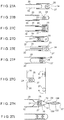
- Figures 27A-27I illustrate variations of the zipper 24, including profiles 25, 27, with respect to their attachment to front and rear sidewalls 20, 22 of web material 102, as well as different configurations of web material 102 as in Figures 27E and 27F .
- Figures 27A, 27E and 27F relate to constructions where the zipper is attached to the outside of the folded web material (also see Figures 6E and 6G ).
- many different kinds of zippers can be used, such as hinged zippers, slider zippers, flangeless (string) zippers and any of the zippers disclosed in U.S. Patent No. 6,360,513 entitled "Resealable Bag for Filling with Food Product(s) and Method", to Strand et al.; U.S. Patent No.
- the forming and filling operations may take place at separate times and places, at the same time and place.
- the forming and filling apparatus and machinery may be on separate manufacturing lines or on an integrated manufacturing line.
- the package of Figure 3A (resulting from the method and apparatus of one of Figures 8A-G and Figures 9A-C ) is inverted.
- Former 300 opens up the package 10 so that first and second interior vertical folds 38, 38', 40, 40' become the corners of the semi-rigid container 12, and a product volume is created within the semi-rigid container 12. This typically includes applying opposing forces on the semi-rigid container 12 near cross seals 21, 23 as illustrated by the arrows labeled "F" on the far left of Figure 12 .
- first and second oval-shaped dots of glue 51, 53 are placed on one side of front of header 18 and the header 18 is folded so that first and second oval-shaped dots of glue 51, 53 cover and are glued or otherwise secured to respective first and second oval-shaped partially scored portions 47, 49.
- Mandrel 303 which may be reciprocating, may be used in combination with first sealer 302 to assure a square shape of the semi-rigid container 12 and further to assure reliable gluing by dots 51, 53.
- other methods of attaching header 18 to the sides of the formed semi-rigid container 12 may be used as previous described.
- First folder 306 folds along first and second interior horizontal folds 46, 46', 48 and seals to form fin seal 52 and triangular ears 58, 60 as shown in Figure 4A and 4B .
- First folder 306 may be implemented as an inverted configuration of the band sealer 310 shown in Figures 13 and 14 .
- Polytetrafluoroethylene belts 312, 313 grip the material of the fin seal 52 and heated seal bars 314, 315 perform the sealing operation between the front and rear panels 13, 15 thereby completing the fin seal 52.
- First folder 306 may also utilize adhesive for closing the bottom of the package 10.
- Second folder 308 folds the fin seal 52 flush to the package 10 and seals the fin seal 52 to the package 10.
- Third folder 309 seals triangular ears 58, 60 to the bottom of the package 10 (shown in solid) or to the first and second gusseted sides 34, 36 of semi-rigid container 12 (shown in phantom). It may be preferred that the triangular ears 58, 60 be sealed to the bottom of the package 10 for aesthetic purposes and to reduce the possibility of the consumer opening the bottom of the package 10.
- the semi-rigid container 12 may have different bottom folding sections and different ways of folding these sections.
- the packages 10 are filled at a later stage, or are maintained in a continuous chain with perforated lines attaching the cross seals between adjacent packages 10 and stacked in a zig-zag configuration.
- the semi-rigid container 12 is not inverted. After the bottom of the container is formed, the semi-rigid container 12 is filled through the top as described hereinafter with respect to Figures 21A-C .
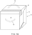
- Figure 15A illustrates, in phantom, two possible positions of an optional handle 62 or 62'.
- One handle 62 may be sealed or otherwise formed on the side of header 18.
- a handle 62' may be sealed or otherwise formed on front panel 13 of package 10.
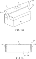
- Figure 15B illustrates, in perspective, an extended header 18 with an aperture 63 therethrough, thereby forming a handle.
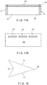
- Figure 16 illustrates an example of header 18 wherein the fold between the first and second sidewalls 20, 22 of header 18 includes a line of weakness 72 (which may include perforations, laser scored lines, tear beads, tear notches, linear tear films, or similar structures, and may be configured as multiple lines) in place of, or in conjunction with, closure 24.
- element 72 may be implemented as a linear tear line. This provides for a header 18 which can be opened by the consumer, but not reclosed.
- Figure 17A illustrates an example of header 18 wherein sidewalls 20, 22 are provided as separate pieces with a peel seal 64 (typically pre-activated) therebetween. Element 64 could likewise be implemented as a tear tape or a pinch-grip zipper.
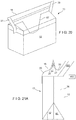
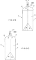
- Figure 18 illustrates a cross-section of an embodiment of semi-rigid container 12 wherein front and rear panels 13, 15 are joined at one end by first gusseted side 34 and directly joined to each other at the other end at point 36' thereby eliminating second gusseted side 36 and providing a triangular cross section which may be advantageous for pouring.
- Figure 19A illustrates an example of a header 18 wherein first and second sidewalls 20, 22 are sealed or otherwise joined to each other along a portion 66 of the top edge, with a zipper 24, including first and second profiles 25, 27, providing a reclosure along the remainder of the top edge.
- portion 66 is formed by sealing together a section of the zipper or the cross-seal 23 is extended across the header 18, leaving only a small section open for pouring out the contents.
- Figure 19B illustrates an example of header 18 wherein a shortened zipper segment 24', configured as a fitment, is inserted into the seal 66 between first and second sidewalls 20, 22 in a configuration adapted to locking after pouring of contents.
- Figure 20 illustrates an example of header 18 including a funnel portion 67 created by forming diagonal seals and cut-outs to the double folded zipper film. Access to the funnel portion 67 is provided by zipper 24. The funnel portion 67 would be extended through header 18 for dispensing product therefrom.
- Figure 21A illustrates an example with top-filling, wherein, first sidewall 20 of header 18 is sealed, glued or attached to the semi-rigid container 12.
- filling apparatus 400 inserts the contents into the package.
- the second sidewall 22 is attached or sealed back to semi-rigid container 12 by sealer 402.
- a zipper flange 27' can be left unattached from its corresponding sidewall 22 and the product is filled by filler between the flange 27' and the sidewall 22.
- the flange 27' and the sidewall 22 are attached together by sealer 402.
- the top of the film of header 18 is slit, the zipper (or reclosure) 24 is opened, product is filled through zipper 24 by filler 400, the zipper 24 is reclosed and the slit edges of header 18 are resealed by sealer 402.
- sealer 402. if separate sheets of web material are used as in Figure 8C , there is no need to slit the top of header 18.
- Figure 22 illustrates an example of package 10 wherein a straw-aperture 68 in header 18, typically initially being sealed but providing an easy opening for the consumer.
- Figure 22 additionally illustrates the structure of the removable header portion 29 illustrated in Figure 27H .
- Further illustrated in Figure 22 is the attachment of a rigid support member 153 to the side of second gusseted side 36, as well as the header structure illustrated and described with respect to Figure 27H .
- Additionally illustrated on Figure 22 is printing on the header and printing on the carton.
- Figure 23 illustrates an example of header 18 wherein reclosure 24 is implemented as a flanged zipper with a slider 70.
- the walls of header 18 include a tear line 72 (typically implemented as a line of weakness, such as perforations, laser scored lines, tear beads, tear notches, linear tear films, or similar structures, and may be configured as multiple lines) which is above the reclosure 24 in the first and second cross seals 21, 23, descending to the area between the top of reclosure 24 and the seal lines 74 joining the zipper flanges and the walls of header 18.
- Slider 70 operates in the conventional way, opening the zipper when moved in a first direction and closing the zipper when moved in a second direction, opposite to the first direction.
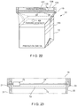
- Figure 24 illustrates an example wherein header 18 is held in place by a cap 80.
- Cap 80 includes rectangular top 82 with side walls 84 extending downwardly therefrom. The rectangular shape of cap 80 aids not only in strengthening or reinforcing the package 10, but also helps the package 18 retain a rectangular cross section.
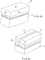
- Figure 25 illustrates an embodiment of package 10 with band 86 holding down the header 18.
- the gusseted sides 35 or 36 may be provided with rigid support member 153.
- Top 82 and band 86 may be breakably attached to semi-rigid container 12, thereby providing tamper evidence, if removed.
- Figure 26 illustrates an example of package 10 with a rectangular semi-rigid container 12 which has four sides 90, 91, 92, 93 thereby forming a square or rectangular shape which is free of gussets.
- the header 18 is glued, sealed or otherwise attached to flattened semi-rigid container 12 by methods previously described so that cross-seal 21 is aligned with the corner or fold formed between sides 90, 93 and cross-seal 23 is aligned with the corner or fold formed between sides 91, 92 (formed oppositely from the corner formed by sides 90, 93).
- This configuration allows the semi-rigid container 12, with the header 18 attached, to lie flat prior to filling (that is, sidewalls 90 and 93 are pressed or folded flat against each other and sidewalls 91, 92 are pressed or folded flat against each other), similar to the previously described examples, however without requiring gussets.
- the zipper 24 extends diagonally across the open top of the semi-rigid container. Similar configurations could be achieved with packages with an even number of sides, greater than four.
Description
- The present disclosure relates to a container portion for producing a package with a carton-type container made from paper, cardboard, chipboard or similar rigid or semi-rigid material with attached thereto a reclosable header section made from plastic, polymer or other flexible material, the reclosable structure being typically a zipper, but not limited thereto. The present disclosure likewise relates to the resulting package.
- In the prior art, it is known to make reclosable flexible plastic bags for the sale of foodstuffs or other consumer products. The bags or packages, while well suited for their intended uses, have typically not been used for food products that would easily be crushed or damaged during shipment. Additionally, such bags or packaging can result in inefficiencies in storage, transportation and display.
- Likewise, traditional cardboard boxes are well-known for the packaging and marketing of such well-established products as cereal. However, these boxes typically are heavy and require an internal waxed paper or similar liner, typically tearable and therefore not resealable and do not protect the contents after initial opening. This increases manufacturing costs and typically does not allow the package to be filled completely with product, thereby resulting in inefficiencies in space, which increases the costs for storage, transportation and display of the product. Therefore, many of these traditional cardboard boxes, particularly those with a tearable plastic liner, have been less than satisfactory in their reclosable capabilities.
- There have been several attempts at packages to address these deficiencies, but none have been entirely satisfactory. These previous attempts include those disclosed in
U.S. Patent No. 7,524,111 entitled "Rigid-Bottomed Resealable Bag with Handles", issued on April 28, 2009 to Williams;U.S. Patent No. 7,207,716 entitled "Flexible Container Having Flat Walls", issued on April 24, 2007 to Buchanan;U.S. Patent No. 7,160,029 entitled "Enclosure for Resealing a Package and Method Therefor", issued on January 9, 2007 to Bein;U.S. Patent No. 6,908,422 entitled "Reclosable Packaging Bag and Method for Manufacturing Same", issued on June 21, 2005 to Ichikawa et al.;U.S. Patent No. 6,110,512 entitled "Package and Merchandiser", issued on August 29, 2000 to Teasdale;U.S. Patent No. 6,063,416 entitled "Procedure and Package to Enable Peg Display of Food Pouch in Tent-Style Paperboard Carton", issued on May 16, 2000 to Teasdale et al.;U.S. Patent No. 4,691,373 entitled "Zipper Closure with Unitary Adhesive Cover Sheet", issued on September 1, 1987 to Ausnit; andU.S. Published Patent Application No. 2005/0194386 , entitled "Zipper Box Covers" published on September 8, 2005 for Shai; and Japanese Patent No.2002104511 US 3,083,890 ,EP 0 130 666 andGB 1 575 502claim 1. - It is therefore an object of the present disclosure to provide a reclosable package which has rigid walls thereby providing a high capacity, space-efficient package with a flat printing surface thereby providing protection for the packaging of crushable or delicate products.
- It is therefore a further object of the present disclosure to provide a package which is light in weight and which is typically reclosable.
- These and other objects are attained by the present disclosure by providing a package, along with a method and apparatus for the production thereof, which includes a rigid or semi-rigid carton-type container and, attached thereto, a plastic, polymer, or similar flexible header, typically with a reclosable zipper configuration, but not limited thereto.
The invention provides a container portion for a carton, comprising: - a front portion and a rear portion;
- first and second edges formed by respective first and second exterior folds joining the front portion to the rear portion wherein the front portion and the rear portion form a top and a bottom of the container portion;
- the front portion including a first front interior vertical fold inwardly adjacent from the first edge and a second front interior vertical fold inwardly adjacent from and parallel to the second edge;
- the rear portion including a first rear interior vertical fold inwardly adjacent from the first edge and a second rear interior vertical fold inwardly adjacent from and parallel to the second edge;
- the front and rear portions including respective first front and rear horizontal folds upwardly adjacent from the bottom;
- one of the front portion and the rear portion including a second horizontal fold between the first front or rear horizontal fold and the bottom;
- a first front inclined fold portion extending from the first front interior vertical fold to the bottom; and
- a second front inclined fold portion extending from the second front interior vertical fold to the bottom; characterised in that an angle between a projection of the first and second front interior vertical folds and the respective first and second front inclined fold portions is in the range of 1-4 degrees.
- The container portion may further include:
- a first rear inclined fold portion extending from the first rear interior vertical fold to the bottom; and
- a second rear inclined fold portion extending from the second rear interior vertical fold to the bottom.
- An angle between a projection of the first and second rear interior vertical folds and the respective first and second rear inclined fold portions may be in the range of 1 -4 degrees.
- An angle between a projection of the first and second rear interior vertical folds and the respective first and second rear inclined fold portions may be in the range of 2-3 degrees.
- Further objects and advantages of the disclosure will become apparent from the following description and from the accompanying drawings, wherein:
-
Figure 1 is a perspective view of a package comprising a container portion according to the invention, shown in a filled configuration with a sealed bottom and an upwardly projecting header. -
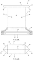
Figure 2 is a perspective view of an embodiment of a package comprising a container portion according to the invention, shown in a filled configuration with a sealed bottom and a flush header. -
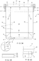
Figure 3A is a plan front view of a package comprising a container portion according to the invention, shown in a flat, unfilled configuration, with an upwardly projecting header and an unsealed bottom. -
Figure 3B is a cross-sectional view of typical material used for the rigid or semi-rigid container portion. -
Figure 3C is a perspective view showing the header attached to the interior of the container portion of the package. -
Figure 4A is a plan view of an embodiment of an inverted package comprising a container portion according to the invention, showing the bottom partially folded, typically after bottom filling, with the bottom fin seal pointing upwardly. -
Figure 4B is a plan view from above of the inverted package ofFigure 4A . -
Figure 5A is a plan view of an embodiment of an inverted package comprising a container portion according to the invention, showing the bottom partially folded, typically after bottom filling, with the bottom fin seal folded flush with the bottom of the package. -
Figure 5B is a plan view from above of the inverted package ofFigure 5A . -
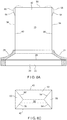
Figure 6A is a plan view of an embodiment of an inverted package comprising a container portion according to the invention, similar toFigure 1 , showing the ears of the bottom folded against the sides of the package and sealed thereto, typically after bottom filling. -
Figure 6B is a side plan view of the inverted package ofFigure 5A . -
Figure 6C is a bottom view of the package, shown with the ears folded and sealed to the bottom of the package. -
Figure 6D is a cross-sectional view of the package, shown with flaps on the front and rear panels for the interior attachment of the header portion. -
Figure 6E is a side view of a further package. -
Figure 6F is a perspective view showing the package ofFigure 6E , with a folded header. -
Figure 6G is a side view of a still further package. -
Figure 6H is a perspective view showing package ofFigure 6G , with a folded header. -
Figure 7 is a perspective view of the top of the rigid or semi-rigid container portion showing a radius or chamfer formed at the corners thereof. -
Figure 8A is a schematic view of a first method and apparatus for producing the package of the present disclosure prior to filling. -
Figure 8B is a schematic view of a second method and apparatus for producing the package of the present disclosure prior to filling, further including a portion in phantom for illustrating a still further variation. -
Figure 8C is a schematic view of a third method and apparatus for producing the package of the present disclosure prior to filling. -
Figure 8D is a schematic view of a fourth method and apparatus for producing the package of the present disclosure prior to filling. -
Figure 8E is a schematic view of a fifth method and apparatus for producing the package of the present disclosure prior to filling. -
Figure 8F is a schematic of view of a sixth method and apparatus for producing the package of the present disclosure prior to filling. -
Figure 8G is a side view of the sixth (seeFigure 8F ) method and apparatus for producing the package of the present disclosure prior to filling. -
Figure 9A is a schematic view of a seventh method and apparatus for producing the package of the present disclosure prior to filling. -
Figure 9B is a schematic view of an eighth method and apparatus for producing the package of the present disclosure prior to filling. -
Figure 9C is a schematic view of a ninth method and apparatus for producing the package of the present disclosure prior to filling. -
Figure 10 is a perspective view of the ultrasonic apparatus used to form the cross-seals in an aspect of a method and apparatus for producing the package. -
Figure 11 is a perspective view of an ultrasonic apparatus used to form three cross-seals simultaneously in an aspect of a method and apparatus for producing the package. -
Figure 12 is a schematic of a method and apparatus of the present disclosure for bottom filling and sealing the packages. -
Figure 13 is a top view of a band sealer used for forming the bottom fin seal in an aspect of a method and apparatus of the present disclosure. -
Figure 14 is a side view of the band sealer ofFigure 13 forming a bottom fin seal for an inverted package in an aspect of a method and apparatus of the present disclosure. -
Figure 15A is a plan view of a package of the present disclosure, showing two alternative handle positions. -
Figure 15B is a perspective view of a package of the present disclosure, showing a handle built into the header. -
Figure 16 is a plan view of a header of a package of the present disclosure, wherein the header is opened by a perforated line or similar line of weakness. -
Figure 17A is a plan view of a header of a package of the present disclosure, wherein the header is opened by way of a pre-activated peel seal. -
Figure 17B is a plan view of discrete zipper segments on a length of web material. -
Figure 18 is a top plan view of a triangular rigid or semi-rigid portion of a package of the present disclosure, thereby allowing for improved pouring from the package in some instances. -
Figure 19A is a perspective view of a header of a package of the present disclosure, wherein the zipper extends only partially across the top of the header. -
Figure 19B is a perspective view of a header of a package of the present disclosure, wherein a shortened zipper is provided across a portion of the top of the header. -
Figure 20 is a plan view of a header of a package of the present disclosure, showing the zipper providing access to a pour spout. -
Figure 21A is a diagram of a package of the present disclosure, wherein the package is filled between the container and the web of the header material. -
Figure 21B is a diagram of a package of the present disclosure, wherein the package is filled between the zipper and the header. -
Figure 21C is a diagram of a the package of the present disclosure, wherein the package is filled between the zipper profiles. -
Figure 22 is a diagram of several variations of a package of the present disclosure, wherein a straw aperture is formed in the header, the header is provided with a tear-away compartment with printed material, and wherein the side of the carton includes a reinforcing member. -
Figure 23 is a plan view of a header with a slider zipper and a tear-away portion. -
Figure 24 illustrates a package of the present disclosure with a cap placed over the top of the package. -
Figure 25 illustrates a package of the present disclosure with a reinforcing band placed around the package. -
Figure 26 illustrates a package of the present disclosure, which is free of gussets and includes a.diagonally oriented zipper spanning opposing corners of the container portion. -
Figures 27A-27I illustrate various zipper and web material cross sections which may be used in packages of the present disclosure. - Referring now to the drawings in detail wherein like numerals indicate like elements throughout the several views, one sees that
Figure 1 is a perspective view of apackage 10 of the present disclosure.Package 10 includes a rigid, semi-rigid or fibrous carton-type container 12, typically with a central layer 164 (Figure 3B ) made from a paper product such as fiberboard or chipboard and aninterior surface 166 with an oxygen barrier and a moisture barrier and a poly-coatedouter layer 162, but is not limited thereto (hereinafter, collectively referred to as a "semi-rigid container").Semi-rigid container 12 is typically initially provided in a flat configuration as shown inFigure 3A with an open top ormouth 14 and anopen bottom 16.Package 10 further includes a plastic or polymeric header 18 (typically applied by heat, adhesive or glue) which includes first andsecond sidewalls Figure 6B ), but is not limited thereto. Other examples of reclosures include, but are not limited to, flanged zippers with opening lips, flanged tamper-resistant zippers, tamper-evident zippers, flanged zippers with sliders (seeFigure 23 ), flanged zippers without sliders, string (flangeless) zippers, double zippers (seeFigure 27I ), multiple track zippers, zippers with a tear line, a zipper with flanges connected above the locking elements, zippers with flanges connected below the locking elements, leak-resistant zippers, zippers with a peel seal, hinged zippers, zippers with spot seals, zippers with eyemarks, partly sealed zippers, zippers with shape-retaining characteristics, pinch grip pull zippers (i.e., lower product side opening strength than consumer side opening strength), zipper tape (especially for applications involving frozen foods), hook-and-eye (i.e., Velcro®), reclosable adhesives, perforated cap zipper tape, laminated zipper tape with a tear bead, zippers with a weakened line of resistance, zippers with a wedge, zippers with a stabilizing post, zippers with guide ribs, zippers with a compression post, and fitments. These terms are known to those skilled in the art, and the corresponding zippers are disclosed in patents mentioned hereinafter. Additionally, in some applications, a peel seal may be substituted for the reclosure. Similarly, examples of the web from whichheader 18 is manufactured includes, but are not limited to, film with eyemarks, printed film (seeFigure 22 ), film with cut-outs, film with diagonal seals and film with tear-lines. Theheader 18 is sealed or glued to themouth 14 ofsemi-rigid container 12. First and second cross-seals 21, 23 or other methods of attachment are formed at the ends ofheader 18 between the sidewalls 20, 22, immediately outwardly adjacent from first and second folded edges (or first and second exterior folds) 30, 32. The first and second cross-seals 21, 23 further typically include respective first and second side incisions ornotches header 18 into the position shown inFigure 2 . Other shapes, such as single or multiple radius cut-outs are also envisioned. It is noted that it is envisioned that some applications may fold theheader 18 onto the top of thepackage 10. However, it will be preferred in many applications that the reclosure orzipper 24 not be bent 180 degrees. Theheader 18 may be made with bio-degradable plastic. Additionally, in such an embodiment, the sealant forsemi-rigid container 12 would also be made bio-degradable. - As shown in
Figure 3A ,semi-rigid container 12 is typically initially provided in a flat state withfront panel 13 andrear panel 15.Semi-rigid container 12 is typically partially or fully poly-coated on exterior surface 162 (Figure 3B ), particularly in the areas where heat sealing is required, such as the top ofsemi-rigid container 12 whereheader 18 is attached, and the portions ofsemi-rigid container 12 where the bottom is sealed shut before or after filling. Alternately, adhesive is applied in the required areas and the attachment is done by these adhesives. Additionally, interior coating or lamination may include other materials required for the necessary barrier properties, including hermeticity and oxygen-moisture barriers. While illustrated inFigure 3A (seeFigure 22 ), front andrear panels Front panel 13 andrear panel 15 are joined to each other by first and second foldededges gusseted sides semi-rigid container 12 in the expanded or filled configuration as shown inFigures 1 and 2 .Front panel 13 ofsemi-rigid container 12 further includes first and second front interiorvertical folds edges Figures 1 and 2 , first and second front interiorvertical folds front surface 42 to thegusseted sides semi-rigid container 12, seeFigures 5A and 5B , forming the transition from therear surface 43 to thegusseted sides Figure 7 , as well asFigure 3A , the upper ends ofvertical folds chamfered sections semi-rigid container 12 during folding and further to reduce the likelihood of the material ofsemi-rigid container 12 forming a point to puncture the material ofheader 18. Similarly, as shown inFigure 7 , in order to prevent leakage between header 18 (not shown inFigure 7 ) andsemi-rigid container 12, extra dots of glue (indicated as "G") are provided at the top of first and second foldededges gusseted sides semi-rigid container 12 is typically formed from a single sheet of material with aseam 35 formed at the overlapping joinder of the edges (shown inFigure 7 as occurring at second interior vertical fold 40) an extra dot of glue (indicated as "G' ") is provided at the top ofseam 35 in order to prevent leakage between thesemi-rigid container 12 and theheader 18 due to the transition in thickness caused byseam 35. Other embodiments may use an even number (four or greater) of panels. - Returning to
Figure 3A , one sees that first and second interior horizontal folds 46, 48 are formed onfront panel 13 adjacent to the bottom 16. Similar first interior horizontal fold 46' is formed on therear panel 15 ofsemi-rigid container 12, seeFigures 5A, 5B . The first interior horizontal folds 46, 46' are used to form the transition to thebottom surface 50 while the second interiorhorizontal fold 48 is used to form thefin seal 52 as shown inFigures 4A, 4B ,5A and 5B . A second horizontal fold is not illustrated on therear panel 15, as typically, only one ofpanels fin seal 52 to fold in a specific direction. As shown in the area of detail ofFigure 3A , the lower portions of first and second front interiorvertical folds inclined fold portions Figure 3A , an angle of typically 1-4 degrees, or preferably 2-3 degrees in most applications, is formed between the projection of respective front interiorvertical folds 38, 40 (with substantially identical construction on the rear of semi-rigid container 12) and inwardlyinclined fold portions inclined fold portions semi-rigid container 12 as the inwardlyinclined fold portions open bottom 16. This aids in the subsequent folding of thesemi-rigid container 12 into thepackage 10. - As further shown in
Figure 3A , corresponding first and second oval-shaped partially scoredportions 47, 49 (typically cutting through a first layer of a multi-laminate or coated surface, however other similar methods, such as compressing, are considered to be within the definition of scoring) are formed with a vertical major axis onsemi-rigid container 12 immediately belowheader 18, outwardly adjacent from first and second front interiorvertical folds 38, 40 (thereby being located within the gusseted sides after thepackage 10 has been formed). During the formation of thepackage 10 from thesemi-rigid container 12 andheader 18, corresponding first and second oval-shaped dots ofglue 51, 53 (with a horizontal major axis) are placed on one side of front ofheader 18, typically above reclosure orzipper 24 and inwardly adjacent from respective first and second cross-seals 21, 23. Additionally, a dot ofglue 55 may be placed just below the mid-point of the top edge ofheader 18. Typically, hot melt glue is used, but other glues or adhesives may be applicable to various applications. During formation of thepackage 10 from thesemi-rigid container 12 andheader 18, theheader 18 is folded down against the sides of the formedsemi-rigid container 12 so that first and second oval-shaped dots ofglue portions glue 55 tacks the top edge ofheader 18 against the folded-downsidewall 20. Thereafter, when the user lifts theheader 18 so as to break the connection formed by first and second oval-shaped dots ofglue portions semi-rigid container 12, with little or no unsightly fiber tears. First and second oval-shaped partially scoredportion semi-rigid container 12. Otherwise, the front and rear views ofsemi-rigid container 12 are substantially identical. Alternately, releasable configurations may be used to attach the folded header to the sides of the formed semi-rigid container, such as, but not limited to, releasable adhesives, hook-and-eye (Velcro®), multiple strips, etc. - First
diagonal fold 54 extends from the intersection of first interiorvertical fold 38 and firsthorizontal fold 46 to the intersection of first foldededge 30 and secondhorizontal fold 48. Similarly, seconddiagonal fold 56 extends from the intersection of second interiorvertical fold 40 and firsthorizontal fold 46 to the intersection of second foldededge 32 and secondhorizontal fold 48. Additionally, as shown inFigure 3A , the lower corners are removed by first and secondlower cuts horizontal fold 48 to opposite ends of the bottom 16 of thesemi-rigid container 12. This results in diagonal ends onfin seal 52 as shown inFigure 4A . As shown inFigures 4B ,5B and6B , similar first and second diagonal folds 54', 56' are formed on therear panel 15 ofsemi-rigid container 12. The first and seconddiagonal folds triangular ears Figures 4A, 4B ,5A, 5B and shown in the final sealed flush position inFigures 1, 2 ,6A and6B . -
Figures 6E and 6F illustrate afurther package 10, wherein first andsecond sidewalls seal 119 either joins the two separate sheets or is formed in a central location on the single sheet.Sidewall 20 includes a line of weakness 72 (which may include perforations, laser scored lines, tear beads, tear notches, linear tear lines, a peel seal, or similar structures, and may be configured as multiple lines) with first and second flanges 25', 27' ofzipper 24 extending over line ofweakness 72 and sealed tofirst sidewall 20 on opposite sides of line ofweakness 72.Zipper 24 further includes anopening zipper flange 123 extending therefrom. In this position, thezipper 24 is placed on the front of theheader 18, in an off-central rather than central position. A similar alternative embodiment would attach thezipper 24 on the interior offirst side wall 20. -
Figures 6G and 6H illustrate a stillfurther package 10 wherein thesidewalls flanged zipper 24 withslider 70 is sealed to the exterior thereof (first flange 25' sealed tosidewall 20 and a second flange 27' sealed to sidewall 22) thereby allowing the consumer to operate theslider 70 to open thezipper 24 and thereby gain access to the contents of thepackage 10. -
Figures 8A-14 illustrate methods and apparatus for producing thepackages 10 ofFigures 1-7 .Figures 8A-G and9A-C illustrate methods and apparatus for producing the unfilled flat packages ofFigure 3A . InFigure 8A (with many similar elements shown in the subsequent figures), astack 11 of pre-made or previously made foldedsemi-rigid containers 12 is provided to a sequential feeder 290 (other sequential feeding apparatus, such as an upstream conveyor or pick-and-place apparatus, may be substituted for thestack 11 and sequential feeder 290), and thesemi-rigid containers 12 are fed sequentially in a machine direction by a servo-drivenconveyor 103.Web material 102 is provided from aspool 100, with periodic eyemarks 104 (in some applications, cut-outs in the web material could be substituted for eyemarks), the detection of which by eye-mark detector 111 is used to time the sequential feeding ofsemi-rigid containers 112 bysequential feeder 290 to conveyor 103 (the registration provided by the eyemarks 104 and the detection thereof is typically only required if theweb material 102 has graphics or other printing with defined locations for the beginning and end of adjacent headers, seeFigure 22 ). Alternatively, the detection of theperiodic eyemarks 104 can be used to vary the speed of theconveyor 103 so that the semi-rigid containers are delivered with the correct registration with respect to theweb material 102. Length ofzipper material 202 is provided fromspool 200 and is sealed to length ofweb material 102 at sealing and folding station 106 (length ofzipper material 202 may be configured without sliders, with pre-mounted sliders, or with sliders mounted by optionalslider mounting station 204 shortly after the zipper is provided fromspool 200 or mounting station 204' can be located after the zipper material is attached to the web material as shown inFigure 8A ). This sealing may be done by attaching a first flange of an interlockedzipper material 202 to unfoldedweb material 102 and then attaching the second flange after theweb material 102 is folded around thezipper material 202. Alternately, the separate, unlocked profiles ofzipper material 202 may be attached to theweb material 102 and theweb material 102 thereafter folded so that the profiles ofzipper material 202 are aligned and interlocked (see the alternative illustrated in phantom inFigure 8B ). In another alternative, the interlockedzipper material 202 may be introduced between a foldedweb material 102 and then sealed or attached thereto. In yet another alternative of the method, the zipper is attached to separate web materials. In such a method the zipper is either attached to one web in an unlocked condition, one section to each web, and thereafter, the zipper is aligned and interlocked or one side of an interlocked zipper material can be attached to one web material. Then the other web material can be attached to the other side of the zipper material. In these embodiments, the zipper can be separated at a later stage for filling the semi-rigid container through the zipper. Additionally, while the preferred method of attaching together the zipper, web, and semi-rigid containers requires several steps, this may be done in fewer steps or even simultaneously. - Typically, releasable dots of glue (other similar methods may be used) are applied to the length of web material at
glue station 107 for the purpose of attaching theheader 18 to the outside of formedsemi-rigid container 12. At web sealing (or attaching)station 108, the length of web 102 (with thezipper 202 attached thereto) is folded (the lateral edges of which thereby form first andsecond sidewalls header 18 ofFigures 1-6 ) so as to contactsemi-rigid containers 12. The lateral edges ofweb material 102 are glued, sealed or otherwise fastened to front andrear panels semi-rigid container 12 by web sealing or attachingstation 108.Sealing station 108 typically includes compression rollers and a heated bar on both sides of the web. The sealing station may include multiple heated seal bars, wherein thesemi-rigid container 12, with theheader 18 in position, passes through these heated bars with little to no contact pressure. After each set of seal bars, thecontainer 12 andheader 18 pass through compression rollers. The compression rollers set the film-to-film seal (i.e., cross-seals 21, 23) between thesemi-rigid containers 12 and the film-to-container seal over thecontainers 12. These compression rollers can be free-spinning or driven. Additionally, it has been found that by pre-tensioning the film ofheader 18 during sealing, that thepackage 10 becomes more rigid. Thesemi-rigid containers 12 with theweb material 102 attached (with thezipper material 202, in turn, attached to web material 102) move in the machine direction. A cross-sealer 110 with typically threecross-seal bars Figure 11 ) reciprocates so that it momentarily travels in the machine direction, tracking the movement of thesemi-rigid containers 12 and the web material 102 (withzipper material 202 attached thereto), and engages theweb material 102 so that a first cross-seal 21 and adjoiningsecond cross-seal 23 of an adjacent package are simultaneously formed in three successive inter-package gaps, typically without the necessity of slowing or stopping the travel ofweb material 102. The use of multiple cross-seal bars (typically ultrasonic, but may include heat welding) along with the synchronized travel with theweb material 102 allows for a prolonged dwell time, thereby improving sealing qualities, while maintaining high production rates. In some embodiments, a lesser or greater number of cross-seal bars may be implemented. The cross-sealer 110 then travels in the opposite direction from the machine direction to position itself for the cross-sealing operation with the successive or consecutive three inter-package gaps. Thecross-seal bars Figure 10 . The reverse knurled surface creates a multitude of small pockets for the polymeric or similar material to flow during the sealing or welding of the cross-seals 21, 23. This produces high quality and aesthetically appealing cross-seals in half the time of heat and pressure sealing. It also typically removes the ambient heat that damages film during long machine stops.Figures 8A-G and9A-C illustrate method and apparatus of attaching zipper web material to the outside of foldedsemi-rigid containers 12. However, such zipper material can be attached to the inside of thesemi-rigid containers 12. In such an embodiment, theedges gussets gussets panels Figure 6D ,panels 13, 15 (as well asgussets 34, 36) are provided with upwardly facing flaps 13', 15' between and to the inside of which zipper webmaterial forming header 18 is attached as inFigure 3C . - The
web material 102 in the inter-package gaps is then severed by cuttingstation 120, resulting in the flat andunfilled packages 10 ofFigure 3A . Alternately, in lieu of cutting, perforations can be made in the cross-seals bystation 120, thereby leaving the packages in a concatenated chain. -
Figure 8B shows a similar method and apparatus, wherein no eyemarks are provided on the web material 102 (typically because no graphics are provided on theweb material 102 which would require critical registration) and wherein theconveyor 103 is a servo-driven chain with periodically spacedadjustable lugs 105 for engaging the trailing edges ofsemi-rigid containers 12 thereby assuring accurate spacing of thesemi-rigid containers 12. Further illustrated inFigure 8B , in phantom, is a second source ofzipper material 200B, whereinsource 200 would include a first interlockable profile andsource 200B would include a second interlockable profile. The separate, unlocked profiles ofzipper material 202 may be attached to theweb material 102 and theweb material 102 thereafter folded so that the profiles ofzipper material 202 are aligned and interlocked - As shown in
Figure 8C , another alternative is to provide two separate sheets ofweb respective spools web stations sheet web station 109. However, if at a later stage, the then-formed container is to be filled through the zipper, thetop edges - As shown in
Figure 8D , another alternative is to feed two sheets ofweb zipper 202 to sealingstation 106 wherein a first profile ofzipper 202 is sealed toweb 102A and a second profile is sealed toweb 102B simultaneously or at a later station. Again, however, if at a later stage, the then-formed container is to be filled through the zipper, thetop edges web station 109.Figure 27H is a representative cross section of what may be produced by this method and apparatus, showing, in particular, lines ofweakness 72 or similar opening structure (which may include perforations, laser scored lines, tear beads, tear notches, linear tear lines, a peel seal, or similar structures, and may be configured as multiple lines) formed insidewalls zipper 24 after removal ofremovable header portion 29. Further illustrated inFigure 27H ispocket 133 formed betweenseals similar material 138 therein. This structure is likewise illustrated inFigure 22 . - As shown in
Figure 8E , segments of zipper material, resulting indiscrete zippers 24, may be fed to the length ofweb material 102 byzipper feeder 206 as shown inFigure 17B resulting in a spaced-apart configuration. This may avoid having the zipper profile in cross-seals 21, 23, but requires accurate registration of thezippers 24 with respect to theweb material 102. In this alternative the zipper segments may be applied toweb material 102 in line with the web direction or at an angle to it. - As shown in
Figures 8F and 8G , stack 11 is implemented as a magazine withcontainers 12 stacked vertically therein.Sequential feeder 290 is implemented as a conveyor belt.Conveyor belt 290 pulls asingle container 12 through a feed gate which allows only the thickness of one box to pass through.Containers 12 are then engaged in a nip formed between upper and lower conveyor pullbelts belts conveyor belt 290 in order to control the gap betweensuccessive containers 12. The edge ofcontainers 12 is sensed by electric eye 296 which controls the operation of glue dot applicator 502 (similar to that shown inFigure 9C ) which applies glue dots to thecontainers 12. -
Figures 9A and9B disclose methods and apparatus similar to those ofFigures 8A and8B , except thatweb material 102 is supplied with the length ofzipper material 202 already sealed thereto. If theweb material 102 is provided in a folded state, then folding within the illustrated apparatus is not required. -
Figure 9C discloses a method and apparatus wherein the length ofweb material 102 is supplied with the length ofzipper 202 already attached thereto. The length ofweb material 102 is fed in open configuration at a right angle (i.e., perpendicularly) to the direction of travel of thesemi-rigid containers 12. The length of web material 102 (withzipper 202 attached) is then brought into alignment with the direction of travel of semi-rigid containers byroller 500. Glue spots are applied byapplicator 502 and guidingrollers web material 102 over the succession ofsemi-rigid containers 12. - Typically, the resulting
header 18 comprises web reclosure material, wherein the distance between the edges of theheader 18, when spread apart, is greater than the distance between the edges of the sides of thesemi-rigid container 12 when thesemi-rigid container 12 is unfolded and formed (i.e., the distance between first and second front interiorvertical folds 38, 40). -
Figures 27A-27I illustrate variations of thezipper 24, includingprofiles rear sidewalls web material 102, as well as different configurations ofweb material 102 as inFigures 27E and 27F . It should be noted thatFigures 27A, 27E and 27F relate to constructions where the zipper is attached to the outside of the folded web material (also seeFigures 6E and 6G ). As stated previously, many different kinds of zippers can be used, such as hinged zippers, slider zippers, flangeless (string) zippers and any of the zippers disclosed inU.S. Patent No. 6,360,513 entitled "Resealable Bag for Filling with Food Product(s) and Method", to Strand et al.;U.S. Patent No. 7,137,736 entitled "Closure Device for a Reclosable Pouch" to Pawloski;U.S. Patent No. 5,972,396 entitled "Flexible Package Having a Reclosable Zipper" to Jurgovan;U.S. Patent No. 6,030,122 entitled "Pinch-Grip Zipper" to Ramsey;U.S. Patent No. 6,347,885 entitled "Reclosable Package Having Zipper Closure, Slider Device and Tamper-Evident Structure" to Buchman;U.S. Patent No. 6,427,421 entitled "Method of Manufacturing Recloseable Packages" to Belmont;U.S. Patent No. 4,846,585 entitled "Easy Open Bag Structure" to Boeckmann;U.S. Patent No. 4,874,257 entitled "Method of Forming a Closed Filled Bag, a Bag Construction and an Apparatus for Forming the Bag" to Inagaki;U.S. Patent No. 6,299,353 entitled "Zipper for Reclosable Container with Apertures Passing Through Female Profile" to Piechocki;U.S. Patent No. 6,955,465 entitled "Powder-Resistant Flexible Zipper For Reclosable Packaging" to Machacek;U.S. Patent No. 7,241,046 entitled "Watertight Closure for a Reclosable Package" to Piechocki;U.S. Patent No. 6,609,827 entitled "Bag Having Slider-Actuated Complementary Closure Strips and a Leakproofing Structure" to Bois et al.;U.S. Patent No. 3,325,084 entitled "Pressure Closable Fastener" to Ausnit;U.S. Patent No. Re. 34,554 entitled "Bags with Reclosable Plastic Fastener Having Automatic Sealing Gasket Means" to Ausnit;U.S. Patent No. 5,520,463 entitled "Foamed Zipper" to Tilman;U.S. Patent No. 4,787,880 entitled "Method of Making Extruded Zipper Strips and Bags Containing the Same" to Ausnit;U.S. Patent No. 6,177,172 entitled "Zippered Film and Bag" to Yeager;U.S. Patent No. 6,021,557 entitled "Process of Making a Zipper for a Reclosable Thermoplastic Bag" to Dais et al.;U.S. Patent No. 7,478,950 entitled "Variable Alignment Slider Zipper for Reclosable Bags" to Plourde et al.;U.S. Patent No. 4,925,316 entitled "Reclosable Bag Having an Outer Reclosable Zipper Type Closure and Inner Non-Reclosable Closure" to Van Erden et al.;U.S. Patent No. 4,923,309 entitled "Tamper-Evident Package" to Van Erden;U.S. Patent No. 5,509,734 entitled "Wedge Activated Zipper" to Ausnit;U.S. Patent No. 4,736,451 entitled "Extruded Zipper Having Combination Stabilizing and Differential Opening Means" to Ausnit;U.S. Patent No. 5,412,924 entitled "Method of Making Reclosable Plastic Bags on a Form, Fill and Seal Machine" to Ausnit;U.S. Patent No. 3,959,856 entitled "Interlocking Separable Fastener" to Ausnit;U.S. Patent No. 6,131,370 entitled "Zipper Applied Across a Film in Transverse Direction" to Ausnit;U.S. Patent No. 6,863,754 entitled "Apparatus and Method for Manufacturing Reclosable Bags Utilizing Zipper Tape Material" to Wright et al.;U.S. Patent No. 6,290,392 entitled "Reclosable Plastic Bag with Deformable, Stay-Open Inlay" to Sandor;U.S. Patent No. 3,054,434 entitled "Bag Closure" to Ausnit;U.S. Patent No. 4,665,552 entitled "Zipper Equipped Bags and Method of and Means for Manually Filling and Separating Them" to Lems et al.;U.S. Patent No. 5,902,427 entitled "Fastener Arrangement with Dual Purpose Cover Sheet" to Zinke et al.;U.S. Patent No. 5,174,658 entitled "Self-Expanding and Reclosable Flexible Pouch" to Cook et al.;U.S. Patent No. 6,827,491 entitled "Wide Open Feature for Reclosable Bags" to Kohl et al.;U.S. Patent No. 6,899,460 entitled "Storage Bag with Openly Biased Mouth" to Turvey et al.; andU.S. Patent No. 6,167,597 entitled "High Compression Zipper" to Malin. A typical bottom filling method and apparatus is shown inFigure 12 . It is important to note that the filling apparatus and machinery shown inFigure 12 may be geographically or otherwise spatially separated from the package forming machinery ofFigures 8A-G and9A-C . The forming and filling operations may take place at separate times and places, at the same time and place. The forming and filling apparatus and machinery may be on separate manufacturing lines or on an integrated manufacturing line. The package ofFigure 3A (resulting from the method and apparatus of one ofFigures 8A-G andFigures 9A-C ) is inverted. Former 300 opens up thepackage 10 so that first and second interiorvertical folds semi-rigid container 12, and a product volume is created within thesemi-rigid container 12. This typically includes applying opposing forces on thesemi-rigid container 12 near cross seals 21, 23 as illustrated by the arrows labeled "F" on the far left ofFigure 12 . At first sealer 302 (alternatively characterized as a releasable attacher), as explained with respect toFigure 3A , first and second oval-shaped dots ofglue header 18 and theheader 18 is folded so that first and second oval-shaped dots ofglue portions Mandrel 303, which may be reciprocating, may be used in combination withfirst sealer 302 to assure a square shape of thesemi-rigid container 12 and further to assure reliable gluing bydots header 18 to the sides of the formedsemi-rigid container 12 may be used as previous described. Thereafter, invertedpackage 10 is filled fromfiller 304.First folder 306 folds along first and second interior horizontal folds 46, 46', 48 and seals to formfin seal 52 andtriangular ears Figure 4A and 4B .First folder 306 may be implemented as an inverted configuration of theband sealer 310 shown inFigures 13 and 14 .Polytetrafluoroethylene belts fin seal 52 and heated seal bars 314, 315 perform the sealing operation between the front andrear panels fin seal 52.First folder 306 may also utilize adhesive for closing the bottom of thepackage 10.Second folder 308 folds thefin seal 52 flush to thepackage 10 and seals thefin seal 52 to thepackage 10.Third folder 309 sealstriangular ears gusseted sides triangular ears package 10 for aesthetic purposes and to reduce the possibility of the consumer opening the bottom of thepackage 10. Thesemi-rigid container 12 may have different bottom folding sections and different ways of folding these sections. In alternative embodiments, thepackages 10 are filled at a later stage, or are maintained in a continuous chain with perforated lines attaching the cross seals betweenadjacent packages 10 and stacked in a zig-zag configuration. In another alternative, thesemi-rigid container 12 is not inverted. After the bottom of the container is formed, thesemi-rigid container 12 is filled through the top as described hereinafter with respect toFigures 21A-C . -
Figure 15A illustrates, in phantom, two possible positions of anoptional handle 62 or 62'. Onehandle 62 may be sealed or otherwise formed on the side ofheader 18. Alternatively, a handle 62' may be sealed or otherwise formed onfront panel 13 ofpackage 10. -
Figure 15B illustrates, in perspective, anextended header 18 with anaperture 63 therethrough, thereby forming a handle. -
Figure 16 illustrates an example ofheader 18 wherein the fold between the first andsecond sidewalls header 18 includes a line of weakness 72 (which may include perforations, laser scored lines, tear beads, tear notches, linear tear films, or similar structures, and may be configured as multiple lines) in place of, or in conjunction with,closure 24. Similarly,element 72 may be implemented as a linear tear line. This provides for aheader 18 which can be opened by the consumer, but not reclosed. Similarly,Figure 17A illustrates an example ofheader 18 whereinsidewalls Element 64 could likewise be implemented as a tear tape or a pinch-grip zipper. -
Figure 18 illustrates a cross-section of an embodiment ofsemi-rigid container 12 wherein front andrear panels gusseted side 34 and directly joined to each other at the other end at point 36' thereby eliminating secondgusseted side 36 and providing a triangular cross section which may be advantageous for pouring. -
Figure 19A illustrates an example of aheader 18 wherein first andsecond sidewalls portion 66 of the top edge, with azipper 24, including first andsecond profiles portion 66 is formed by sealing together a section of the zipper or the cross-seal 23 is extended across theheader 18, leaving only a small section open for pouring out the contents. Similarly,Figure 19B illustrates an example ofheader 18 wherein a shortened zipper segment 24', configured as a fitment, is inserted into theseal 66 between first andsecond sidewalls -
Figure 20 illustrates an example ofheader 18 including afunnel portion 67 created by forming diagonal seals and cut-outs to the double folded zipper film. Access to thefunnel portion 67 is provided byzipper 24. Thefunnel portion 67 would be extended throughheader 18 for dispensing product therefrom. -
Figure 21A illustrates an example with top-filling, wherein,first sidewall 20 ofheader 18 is sealed, glued or attached to thesemi-rigid container 12. Prior to the sealing, gluing, or other attachment ofsecond sidewall 22 ofheader 18 tosemi-rigid container 12, fillingapparatus 400 inserts the contents into the package. Thereafter, thesecond sidewall 22 is attached or sealed back tosemi-rigid container 12 bysealer 402. Alternately, as shown inFigure 21B , a zipper flange 27' can be left unattached from its correspondingsidewall 22 and the product is filled by filler between the flange 27' and thesidewall 22. Thereafter, the flange 27' and thesidewall 22 are attached together bysealer 402. In a further alternative embodiment shown inFigure 21C , the top of the film ofheader 18 is slit, the zipper (or reclosure) 24 is opened, product is filled throughzipper 24 byfiller 400, thezipper 24 is reclosed and the slit edges ofheader 18 are resealed bysealer 402. However, if separate sheets of web material are used as inFigure 8C , there is no need to slit the top ofheader 18. -
Figure 22 illustrates an example ofpackage 10 wherein a straw-aperture 68 inheader 18, typically initially being sealed but providing an easy opening for the consumer.Figure 22 additionally illustrates the structure of theremovable header portion 29 illustrated inFigure 27H . Further illustrated inFigure 22 is the attachment of arigid support member 153 to the side of secondgusseted side 36, as well as the header structure illustrated and described with respect toFigure 27H . Additionally illustrated onFigure 22 is printing on the header and printing on the carton. -
Figure 23 illustrates an example ofheader 18 whereinreclosure 24 is implemented as a flanged zipper with aslider 70. Additionally, the walls ofheader 18 include a tear line 72 (typically implemented as a line of weakness, such as perforations, laser scored lines, tear beads, tear notches, linear tear films, or similar structures, and may be configured as multiple lines) which is above thereclosure 24 in the first and second cross seals 21, 23, descending to the area between the top ofreclosure 24 and the seal lines 74 joining the zipper flanges and the walls ofheader 18.Slider 70 operates in the conventional way, opening the zipper when moved in a first direction and closing the zipper when moved in a second direction, opposite to the first direction. -
Figure 24 illustrates an example whereinheader 18 is held in place by acap 80.Cap 80 includes rectangular top 82 withside walls 84 extending downwardly therefrom. The rectangular shape ofcap 80 aids not only in strengthening or reinforcing thepackage 10, but also helps thepackage 18 retain a rectangular cross section. Similarly,Figure 25 illustrates an embodiment ofpackage 10 withband 86 holding down theheader 18. As previously described with respect toFigure 22 , thegusseted sides rigid support member 153.Top 82 andband 86 may be breakably attached tosemi-rigid container 12, thereby providing tamper evidence, if removed. -
Figure 26 illustrates an example ofpackage 10 with a rectangularsemi-rigid container 12 which has foursides header 18 is glued, sealed or otherwise attached to flattenedsemi-rigid container 12 by methods previously described so that cross-seal 21 is aligned with the corner or fold formed betweensides sides 91, 92 (formed oppositely from the corner formed bysides 90, 93). This configuration allows thesemi-rigid container 12, with theheader 18 attached, to lie flat prior to filling (that is, sidewalls 90 and 93 are pressed or folded flat against each other and sidewalls 91, 92 are pressed or folded flat against each other), similar to the previously described examples, however without requiring gussets. In the open configuration, as shown inFigure 26 , thezipper 24 extends diagonally across the open top of the semi-rigid container. Similar configurations could be achieved with packages with an even number of sides, greater than four. - Thus the several aforementioned objects and advantages are most effectively attained. Although preferred embodiments of the invention have been disclosed and described in detail herein, it should be understood that this invention is in no sense limited thereby and its scope is to be determined by that of the appended claims.
Claims (5)
- A container portion (12) for a carton, comprising:a front portion (13) and a rear portion (15);first (30) and second (32) edges formed by respective first and second exterior folds joining the front portion (13) to the rear portion (15) wherein the front portion and the rear portion form a top (14) and a bottom (16) of the container portion (12);the front portion including a first front interior vertical fold (38) inwardly adjacent from the first edge (30) and a second front interior vertical fold (40) inwardly adjacent from and parallel to the second edge (32);the rear portion (15) including a first rear interior vertical fold (38') inwardly adjacent from the first edge and a second rear interior vertical fold (40') inwardly adjacent from and parallel to the second edge;the front and rear portions including respective first front (46) and rear (46') horizontal folds upwardly adjacent from the bottom (16);one of the front portion and the rear portion including a second horizontal fold (48, 48') between the first front or rear horizontal fold and the bottom;a first front inclined fold portion (139) extending from the first front interior vertical fold to the bottom; anda second front inclined fold portion (141) extending from the second front interior vertical fold to the bottom; characterised in thatan angle between a projection of the first and second front interior vertical folds (38, 40) and the respective first and second front inclined fold portions (139, 141) is in the range of 1-4 degrees.
- The container portion of Claim 1 wherein an angle between a projection of the first and second front interior vertical folds and the respective first and second front inclined fold portions is in the range of 2-3 degrees.
- The container portion of Claim 1, further including:a first rear inclined fold portion (139') extending from the first rear interior vertical fold to the bottom; anda second rear inclined fold portion (141') extending from the second rear interior vertical fold to the bottom.
- The container portion of Claim 3 wherein an angle between a projection of the first and second rear interior vertical folds and the respective first and second rear
inclined fold portions is in the range of 1 -4 degrees. - The container portion of Claim 3 wherein an angle between a projection of the first and second rear interior vertical folds and the respective first and second rear inclined fold portions is in the range of 2-3 degrees.
Priority Applications (1)
| Application Number | Priority Date | Filing Date | Title |
|---|---|---|---|
| EP17155469.4A EP3241777B1 (en) | 2009-10-08 | 2010-09-13 | Carton with plastic reclosable header |
Applications Claiming Priority (3)
| Application Number | Priority Date | Filing Date | Title |
|---|---|---|---|
| US24985209P | 2009-10-08 | 2009-10-08 | |
| US29842910P | 2010-01-26 | 2010-01-26 | |
| PCT/US2010/048615 WO2011043894A1 (en) | 2009-10-08 | 2010-09-13 | Carton with plastic reclosable header |
Related Child Applications (2)
| Application Number | Title | Priority Date | Filing Date |
|---|---|---|---|
| EP17155469.4A Division EP3241777B1 (en) | 2009-10-08 | 2010-09-13 | Carton with plastic reclosable header |
| EP17155469.4A Division-Into EP3241777B1 (en) | 2009-10-08 | 2010-09-13 | Carton with plastic reclosable header |
Publications (3)
| Publication Number | Publication Date |
|---|---|
| EP2485955A1 EP2485955A1 (en) | 2012-08-15 |
| EP2485955A4 EP2485955A4 (en) | 2015-09-09 |
| EP2485955B1 true EP2485955B1 (en) | 2018-03-28 |
Family
ID=43857056
Family Applications (3)
| Application Number | Title | Priority Date | Filing Date |
|---|---|---|---|
| EP10822406.4A Active EP2485954B1 (en) | 2009-10-08 | 2010-09-13 | Carton with plastic reclosable header |
| EP10822404.9A Not-in-force EP2485955B1 (en) | 2009-10-08 | 2010-09-13 | Container portion for a carton with a plastic reclosable header |
| EP17155469.4A Active EP3241777B1 (en) | 2009-10-08 | 2010-09-13 | Carton with plastic reclosable header |
Family Applications Before (1)
| Application Number | Title | Priority Date | Filing Date |
|---|---|---|---|
| EP10822406.4A Active EP2485954B1 (en) | 2009-10-08 | 2010-09-13 | Carton with plastic reclosable header |
Family Applications After (1)
| Application Number | Title | Priority Date | Filing Date |
|---|---|---|---|
| EP17155469.4A Active EP3241777B1 (en) | 2009-10-08 | 2010-09-13 | Carton with plastic reclosable header |
Country Status (9)
| Country | Link |
|---|---|
| US (4) | US10065770B2 (en) |
| EP (3) | EP2485954B1 (en) |
| JP (2) | JP2013507301A (en) |
| KR (2) | KR20120100906A (en) |
| CN (2) | CN102639402B (en) |
| BR (1) | BR112012007966B1 (en) |
| CA (2) | CA2776963C (en) |
| MX (2) | MX358565B (en) |
| WO (4) | WO2011043896A1 (en) |
Families Citing this family (50)
| Publication number | Priority date | Publication date | Assignee | Title |
|---|---|---|---|---|
| US8690046B2 (en) * | 2010-04-29 | 2014-04-08 | Illinois Tool Works Inc. | Self-mating zipper on carton |
| US20110315686A1 (en) * | 2010-06-28 | 2011-12-29 | Mead Johnson Nutrition Company | Refillable Product Dispenser System |
| US10858147B2 (en) | 2012-04-24 | 2020-12-08 | Illinois Tool Works Inc. | Enhancement for package with plastic header |
| US9162801B2 (en) * | 2012-07-11 | 2015-10-20 | Bolso, Llc | Product container |
| JP5439622B1 (en) * | 2013-07-10 | 2014-03-12 | トタニ技研工業株式会社 | Fastener direction change device |
| US9957080B2 (en) | 2013-09-25 | 2018-05-01 | Graphic Packaging International, Llc | Reinforced package |
| US9771176B2 (en) * | 2013-09-25 | 2017-09-26 | Graphic Packaging International, Inc. | Reinforced package |
| US9758275B2 (en) * | 2013-09-25 | 2017-09-12 | Graphic Packaging International, Inc. | Reinforced package |
| US9315296B2 (en) * | 2013-12-19 | 2016-04-19 | Kimberly-Clark Worldwide, Inc. | Packaging for bulky articles with false side gusset |
| CN105934391B (en) * | 2014-01-24 | 2018-12-25 | 株式会社细川洋行 | The joint method of Angle supporting bag, the manufacturing method of Angle supporting bag and laminated body |
| US9701444B2 (en) * | 2014-02-07 | 2017-07-11 | David Fleming Gallagher | Container for articles with dispensing flexible sheet |
| US20160031588A1 (en) * | 2014-07-29 | 2016-02-04 | Frito-Lay North America, Inc. | Snack Food Container |
| US10611512B2 (en) | 2014-07-29 | 2020-04-07 | Frito-Lay North America, Inc. | Snack food container |
| US10722048B2 (en) | 2015-04-16 | 2020-07-28 | Kids2, Inc. | Infant support pillow |
| MX2017013716A (en) | 2015-04-29 | 2018-03-02 | Graphic Packaging Int Llc | Method and system forming packages. |
| WO2016176554A1 (en) | 2015-04-29 | 2016-11-03 | Graphic Packaging International, Inc. | Method and system for forming packages |
| CN107848723B (en) | 2015-07-14 | 2020-09-22 | 印刷包装国际有限责任公司 | Method and system for forming packages |
| ES2907680T3 (en) | 2015-08-21 | 2022-04-26 | Graphic Packaging Int Llc | Reinforced container, cardboard box, combination of a cardboard box preform and a bag, and method of forming a reinforced container |
| US10407199B2 (en) * | 2015-08-28 | 2019-09-10 | Cvp Systems Llc | Packaging apparatus with package dividing seal mechanism |
| GB2552300B (en) * | 2016-07-05 | 2019-07-17 | Elopak As | Anvil device |
| CN108528968A (en) | 2017-03-02 | 2018-09-14 | 菲内尔有限责任公司 | Flexible food container with integrated form closure member |
| US11040798B2 (en) | 2017-08-09 | 2021-06-22 | Graphie Packaging International, LLC | Method and system for forming packages |
| USD887786S1 (en) | 2017-09-19 | 2020-06-23 | Finell Co., LLC | Reusable sealable bowl |
| USD886533S1 (en) | 2017-09-19 | 2020-06-09 | Finell Co., LLC | Reusable sealable medium bag |
| USD874876S1 (en) | 2017-09-19 | 2020-02-11 | Zip Top, Llc | Reusable sealable milk bag and tray |
| USD873083S1 (en) | 2017-09-19 | 2020-01-21 | Zip Top, Llc | Reusable sealable snack bag |
| USD873084S1 (en) | 2017-09-19 | 2020-01-21 | Zip Top, Llc | Reusable sealable sandwich bag |
| USD945826S1 (en) | 2017-09-19 | 2022-03-15 | Zip Top, Llc | Reusable sealable cup |
| USD873075S1 (en) | 2017-09-19 | 2020-01-21 | Zip Top, Llc | Reusable sealable cup |
| USD876891S1 (en) | 2017-09-19 | 2020-03-03 | Zip Top, Llc | Reusable sealable cup |
| USD877568S1 (en) | 2017-09-19 | 2020-03-10 | Zip Top, Llc | Reusable sealable cup |
| USD945828S1 (en) | 2017-09-19 | 2022-03-15 | Zip Top, Llc | Reusable sealable cup |
| USD945827S1 (en) | 2017-09-19 | 2022-03-15 | Zip Top, Llc | Reusable sealable cup |
| USD876172S1 (en) | 2017-09-19 | 2020-02-25 | Zip Top, Llc | Reusable sealable bowl |
| USD886534S1 (en) | 2017-09-19 | 2020-06-09 | Finell Co., LLC | Reusable sealable small bag |
| USD878157S1 (en) | 2017-09-19 | 2020-03-17 | Zip Top, Llc | Reusable sealable cup |
| USD877569S1 (en) | 2017-09-19 | 2020-03-10 | Zip Top, Llc | Reusable sealable cup |
| EP3755646A4 (en) * | 2018-02-20 | 2022-02-16 | O'Neill, Kevin, M. | Lightweight transport, storage and delivery system |
| CN108455005B (en) * | 2018-02-27 | 2023-07-04 | 中国地质大学(武汉) | Portable express box |
| NZ769052A (en) * | 2018-05-14 | 2022-10-28 | Graphic Packaging Int Llc | Method and system for forming packages |
| MX2021000248A (en) | 2018-07-09 | 2021-03-25 | Graphic Packaging Int Llc | Method and system for forming packages. |
| US20200062465A1 (en) * | 2018-08-21 | 2020-02-27 | Illinois Tool Works Inc. | Fold and seal flexible valves |
| EP3867167A1 (en) * | 2018-10-15 | 2021-08-25 | GEA Food Solutions Weert B.V. | Vertical flow-wrapper, bag with a segment of a re-closure means and method to produce re-closable bag |
| CA3111599C (en) * | 2018-11-08 | 2023-12-12 | Kwik Lok Corporation | Tamper evident packaging and methods of manufacturing the same utilizing a non-contact sealing device |
| US11198534B2 (en) | 2019-01-28 | 2021-12-14 | Graphic Packaging International, Llc | Reinforced package |
| US11098940B2 (en) | 2019-03-08 | 2021-08-24 | Zip Top Llc | Flexible container with ice tray |
| EA202192458A1 (en) * | 2019-04-26 | 2022-02-16 | ДжейТи ИНТЕРНЕШНЛ СА | RE-SEALABLE PACKAGING AND METHOD FOR MANUFACTURING RE-SEALABLE PACKAGING |
| US11905070B2 (en) | 2020-03-12 | 2024-02-20 | Illinois Tool Works Inc. | Repulpable zipper for zip packaging |
| DE102020130709A1 (en) * | 2020-11-20 | 2022-05-25 | Focke & Co. (Gmbh & Co. Kg) | Packing for tobacco industry products and method of manufacturing the same |
| US11772849B2 (en) | 2021-06-18 | 2023-10-03 | S. C. Johnson & Son, Inc. | Closure system for pouch or container |
Family Cites Families (133)
| Publication number | Priority date | Publication date | Assignee | Title |
|---|---|---|---|---|
| US2100739A (en) | 1936-03-20 | 1937-11-30 | Shellmar Products Co | Container machine |
| US2434756A (en) * | 1942-10-23 | 1948-01-20 | Ira Milton Jones | Hermetically sealed container and method of making the same |
| US2395663A (en) * | 1943-10-09 | 1946-02-26 | Pneumatic Scale Corp | Carton |
| US3083890A (en) * | 1959-07-04 | 1963-04-02 | Ignell Rolf Lennart | Folding box |
| US3054434A (en) | 1960-05-02 | 1962-09-18 | Ausnit | Bag closure |
| US3113712A (en) * | 1960-11-14 | 1963-12-10 | Bemis Bro Bag Co | Transporting and dispensing container |
| US3325084A (en) | 1965-10-18 | 1967-06-13 | Ausnit Steven | Pressure closable fastener |
| US3396899A (en) * | 1966-12-22 | 1968-08-13 | Owens Illinois Inc | Composite container and sealing means therefor |
| US3750932A (en) * | 1971-07-28 | 1973-08-07 | Inland Container Corp | Container having improved bellows closure and blank for making same |
| US3765593A (en) | 1971-08-13 | 1973-10-16 | Rand Whitney Packaging Corp | Carton having diagonal flip-top corner cap |
| US3959856A (en) | 1975-03-06 | 1976-06-01 | Steven Ausnit | Interlocking separable fastener |
| JPS5546569Y2 (en) * | 1975-12-05 | 1980-10-31 | ||
| GB1575502A (en) * | 1975-12-23 | 1980-09-24 | Unilever Ltd | Containers folded from a blank |
| JPS52163412U (en) * | 1976-06-03 | 1977-12-10 | ||
| US4082216A (en) * | 1977-02-07 | 1978-04-04 | Eli Lilly And Company | Carton and bag container |
| US4185765A (en) * | 1978-07-24 | 1980-01-29 | Champion International Corporation | Hermetic sealed carton |
| JPS56156747U (en) * | 1980-04-24 | 1981-11-21 | ||
| US4347970A (en) | 1980-08-21 | 1982-09-07 | Colgate-Palmolive Company | Container closure |
| US4471884A (en) * | 1982-05-11 | 1984-09-18 | The James River Corporation | Glue flap construction for a lined carton |
| US4495209A (en) * | 1982-06-07 | 1985-01-22 | Whiteside Michael G | Method of forming, filling and hermetically sealing containers |
| IL71516A0 (en) * | 1983-05-04 | 1984-07-31 | Int Paper Co | Carton with hinged opening and perforated hinged opening |
| DE3464877D1 (en) * | 1984-05-05 | 1987-08-27 | Henri Shavit | Apparatus for making a container from a flat blank |
| US4520957A (en) | 1984-07-26 | 1985-06-04 | Ex-Cell-O Corporation | In-folded fin seal end closure |
| US4622693A (en) * | 1985-04-22 | 1986-11-11 | Cvp Systems, Inc. | Collapsible bag and liner combination |
| US4665552A (en) | 1985-06-18 | 1987-05-12 | Minigrip, Inc. | Zipper equipped bags and method of and means for manually filling and separating them |
| US4691373A (en) | 1985-08-05 | 1987-09-01 | Minigrip, Incorporated | Zipper closure with unitary adhesive cover sheet |
| ATE67977T1 (en) * | 1985-11-08 | 1991-10-15 | Minigrip Europe Gmbh | RECLOSABLE FLEXIBLE CONTAINER. |
| US4657176A (en) | 1985-11-25 | 1987-04-14 | Eiwa Sangyo Kabushiki Kaisha | Collapsible box including bag and attached lid |
| US4787880A (en) | 1985-12-23 | 1988-11-29 | Minigrip, Inc. | Method of making extruded zipper strips and bags containing the same |
| US5080253A (en) | 1986-06-02 | 1992-01-14 | The Dow Chemical Company | Reclosable box liner |
| DE3619407A1 (en) * | 1986-06-09 | 1988-05-05 | Pkl Verpackungssysteme Gmbh | GEL PACK |
| US4925316A (en) | 1986-08-11 | 1990-05-15 | Minigrip, Inc. | Reclosable bag having an outer reclosable zipper type closure and inner non-reclosable closure |
| US4736451A (en) | 1986-12-22 | 1988-04-05 | Minigrip, Inc. | Extruded zipper having combination stabilizing and differential opening means |
| AU585174B2 (en) | 1987-01-27 | 1989-06-08 | Fujitokushu Shigyo Company Limited | Bag with zipper and its production method |
| EP0393025B1 (en) * | 1987-12-11 | 1992-04-01 | Schouw Packing A/S | A packaging container, in particular for dry, tricklable products |
| US4846585A (en) | 1988-01-29 | 1989-07-11 | Minigrip, Inc. | Easy open bag structure |
| US4949527A (en) | 1988-06-29 | 1990-08-21 | Zip-Pak Incorporated | Method of forming a reclosable tray |
| JPH0216748A (en) | 1988-07-05 | 1990-01-19 | Nec Corp | Inspection device for semiconductor integrated circuit characteristic |
| US4892414A (en) | 1988-07-05 | 1990-01-09 | Minigrip, Inc. | Bags with reclosable plastic fastener having automatic sealing gasket means |
| JPH0618909Y2 (en) * | 1988-07-21 | 1994-05-18 | 三井東圧化学株式会社 | Cylindrical container |
| US5028147A (en) * | 1988-08-25 | 1991-07-02 | Bell Paper Company | Integrated container for meat products |
| US4923309A (en) | 1989-02-27 | 1990-05-08 | Illinois Tool Works | Tamper-evident package |
| US5067822A (en) * | 1989-04-24 | 1991-11-26 | Reynolds Consumer Products, Inc. | Method of forming recloseable packages, profiles used therein, and packages produced thereby |
| US5024537A (en) | 1990-01-08 | 1991-06-18 | Zip-Pak Incorporated | Tape carried pre-cut zipper |
| US5070584A (en) | 1990-03-09 | 1991-12-10 | Dowbrands Inc. | Zipper for a reclosable thermoplastic bag and a process and apparatus for making |
| US5163269A (en) * | 1990-09-10 | 1992-11-17 | Bryan Foods, Inc. | Method for making reclosable package |
| US5215380A (en) * | 1990-10-19 | 1993-06-01 | Reynolds Consumer Products, Inc. | Reclosable package with tear strip |
| US5174658A (en) | 1991-07-12 | 1992-12-29 | The Procter & Gamble Company | Self-expanding and reclosable flexible pouch |
| US5782733A (en) | 1992-10-26 | 1998-07-21 | Innoflex Incorporated | Zippered film and bag |
| US5422130A (en) * | 1992-11-04 | 1995-06-06 | Pressure Pack, Inc. | Commercially sterile food packaging system |
| US5691026A (en) | 1993-07-27 | 1997-11-25 | Minnesota Mining And Manufacturing Company | Fastener member with a dual purpose cover sheet |
| US5405561A (en) | 1993-08-31 | 1995-04-11 | Dowbrands L.P. | Process for microperforating zippered film useful for manufacturing a reclosable zippered bag |
| US5392589A (en) * | 1993-09-03 | 1995-02-28 | Jebco Packaging Systems, Inc. | Method of constructing a container with unitary spout pull tab |
| JP2863420B2 (en) | 1993-09-14 | 1999-03-03 | 出光石油化学株式会社 | Manufacturing method of bag with articulation tool |
| US5417040A (en) * | 1993-09-20 | 1995-05-23 | Davoren; Gerrard A. | Method of making and filling a resealable bag |
| US5509734A (en) | 1994-01-11 | 1996-04-23 | Minigrip, Inc. | Wedge activated zipper |
| US5412924A (en) | 1994-04-11 | 1995-05-09 | Minigrip, Inc. | Method of making reclosable plastic bags on a form, fill and seal machine |
| US5690600A (en) * | 1994-08-19 | 1997-11-25 | Baxter International Inc. | Retractable web separator |
| US5588279A (en) * | 1994-09-26 | 1996-12-31 | Tetra Laval Holdings & Finance S.A. | Apparatus and method for transporting a container between processing stations of a packaging machine |
| US5694746A (en) | 1994-12-20 | 1997-12-09 | Chung; Yun H. | Paperboard package and method for forming same |
| US5520463A (en) | 1995-05-30 | 1996-05-28 | Minigrip, Inc. | Foamed zipper |
| US5651462A (en) * | 1995-08-23 | 1997-07-29 | Reynolds Consumer Products Inc. | Rigid reclosable packaging |
| US6149304A (en) * | 1997-05-09 | 2000-11-21 | The Procter & Gamble Company | Flexible storage bag with selectively-activatible closure |
| US6030122A (en) | 1998-03-06 | 2000-02-29 | Illinois Tool Works Inc. | Pinch-grip zipper |
| US5941643A (en) * | 1998-04-07 | 1999-08-24 | Triangle Package Machinery Company | Partially zippered pouch and machine for making same |
| US5972396A (en) | 1998-05-15 | 1999-10-26 | Recot, Inc. | Flexible package having a re-closable zipper |
| FR2780037B1 (en) | 1998-06-17 | 2000-09-08 | Flexico France Sarl | BAG COMPRISING ADDITIONAL CLOSING CLOSURE PROFILES |
| US6167597B1 (en) | 1998-07-13 | 2001-01-02 | Illinois Tool Works, Inc. | High compression zipper |
| US6029885A (en) * | 1998-08-27 | 2000-02-29 | Mueller; Charles J. | Rapid assembly box |
| US6047883A (en) * | 1998-09-08 | 2000-04-11 | Westvaco Corporation | Bagless barrier paperboard container with a tamper evident reclosable fitment |
| GB9819825D0 (en) | 1998-09-11 | 1998-11-04 | Wood Colin L H | Eternity caskets |
| US6217497B1 (en) * | 1998-11-09 | 2001-04-17 | Profile Packaging, Inc. | Stand-up apparatus for producing flexible pouches |
| US6110512A (en) | 1998-11-25 | 2000-08-29 | Kraft Foods, Inc. | Package and merchandiser |
| US6063416A (en) | 1999-01-26 | 2000-05-16 | Kraft Foods, Inc. | Procedure and package to enable peg display of food pouch in tent-style paperboard carton |
| US6327754B1 (en) | 1999-05-10 | 2001-12-11 | Pactiv Corporation | Fastener with slider thereon for use in manufacturing recloseable bags |
| US6360513B1 (en) * | 1999-05-11 | 2002-03-26 | Sargento Foods Inc. | Resealable bag for filling with food product(s) and method |
| US6138439A (en) * | 1999-05-21 | 2000-10-31 | Illinois Tool Works Inc. | Methods of making slide-zippered reclosable packages on horizontal form-fill-seal machines |
| US6206571B1 (en) | 1999-06-24 | 2001-03-27 | Alan D. Olin | Flexible bag with resealable pour spout |
| US6477820B1 (en) * | 1999-07-29 | 2002-11-12 | Kraft Foods Holdings, Inc. | Method of making a package with a zipper closure |
| US6863754B2 (en) | 1999-10-12 | 2005-03-08 | Com-Pac International, Inc. | Apparatus and method for manufacturing reclosable bags utilizing zipper tape material |
| US6347885B1 (en) | 2000-01-18 | 2002-02-19 | Reynolds Consumer Products, Inc. | Reclosable package having a zipper closure, slider device and tamper-evident structure |
| AU2001232980A1 (en) * | 2000-01-31 | 2001-08-07 | Cryovac, Inc. | Reclosable pouch |
| US6131370A (en) | 2000-02-09 | 2000-10-17 | Illinois Tool Works Inc. | Zipper applied across a film in transverse direction |
| JP4194229B2 (en) | 2000-03-07 | 2008-12-10 | 株式会社細川洋行 | Reclosable packaging bag and manufacturing method thereof |
| US6299353B1 (en) | 2000-03-28 | 2001-10-09 | Illinois Tool Works Inc. | Zipper for reclosable container with apertures passing through female profile |
| IT1320966B1 (en) * | 2000-03-31 | 2003-12-18 | Gd Spa | RIGID ENVELOPE FOR A PLURALITY OF CIGARETTE PACKAGES. |
| RU2282571C2 (en) | 2000-08-29 | 2006-08-27 | Сосьете Де Продюи Нестле С.А. | Product container and manufacturing method |
| JP3903708B2 (en) | 2000-09-29 | 2007-04-11 | 凸版印刷株式会社 | Bag in carton |
| US6688515B1 (en) * | 2000-10-23 | 2004-02-10 | Meadwestvaco Corporation | Bagless container with reclosable fitment |
| US6520404B1 (en) * | 2000-10-30 | 2003-02-18 | Somerville Packaging Systems, A Division Of Paperboard Industries Corporation | Carton, method of forming same, and carton blank |
| US6290392B1 (en) | 2000-11-06 | 2001-09-18 | Joseph Sandor | Reclosable plastic bag with deformable, stay-open inlay |
| EP1209083B1 (en) | 2000-11-24 | 2004-08-18 | Focke & Co. (GmbH & Co.) | Method and device for manufacturing wrapped packages and bobine |
| US6695757B2 (en) * | 2001-01-12 | 2004-02-24 | Scholle Corporation | Method of manufacturing a standup bag |
| FR2820361B1 (en) * | 2001-02-02 | 2003-07-25 | Flexico France Sarl | PROCESS FOR MANUFACTURING BAGS WITH ADDITIONAL CLOSING PROFILES, MACHINE AND BAGS OBTAINED |
| US6899460B2 (en) | 2001-10-23 | 2005-05-31 | S.C. Johnson Home Storage, Inc. | Storage bag with openly biased mouth |
| US20030101552A1 (en) | 2001-11-30 | 2003-06-05 | Plourde Eric P. | Variable alignment zipper for reclosable bags |
| US20030111521A1 (en) * | 2001-12-17 | 2003-06-19 | Holmes Gordon W. | Gift packaging and method of manufacture thereof |
| US6955465B2 (en) | 2002-04-15 | 2005-10-18 | Illinois Tool Works Inc. | Powder-resistant flexible zipper for reclosable packaging |
| US6827491B2 (en) | 2002-05-14 | 2004-12-07 | Illinois Tool Works Inc. | Wide open feature for reclosable bags |
| US6854886B2 (en) | 2002-06-28 | 2005-02-15 | Illinois Tool Works Inc. | Watertight closure for a reclosable package |
| CN100522013C (en) * | 2002-11-07 | 2009-08-05 | C·W·赞姆比尔公司 | Carton with dispenser |
| US7004378B1 (en) | 2002-12-04 | 2006-02-28 | R & L Engineering, Inc. | Small-article container |
| EP1590253B1 (en) * | 2002-12-09 | 2008-11-05 | Cmd Corporation | Recloseable bag |
| US6840401B2 (en) * | 2002-12-19 | 2005-01-11 | Kimberly-Clark Worldwide, Inc. | Multiple layer baffle structure for dispenser for wipes |
| US20040250510A1 (en) | 2003-01-28 | 2004-12-16 | Paul Dalietos | Apparatus and method for dispensing wrapper and wrapping products |
| US7137736B2 (en) | 2003-05-19 | 2006-11-21 | S.C. Johnson Home Storage, Inc. | Closure device for a reclosable pouch |
| US6840436B2 (en) * | 2003-05-28 | 2005-01-11 | Wen-Tsan Wang | Folding collapsible box |
| US6928794B2 (en) * | 2003-08-01 | 2005-08-16 | 3M Innovative Properties Company | Method and apparatus for making a continuous series of filled pouches |
| CN1819953A (en) | 2003-08-22 | 2006-08-16 | 石崎资材株式会社 | Plastic bag with zipper |
| US20050194386A1 (en) | 2004-03-08 | 2005-09-08 | Moti Shai | Zipper box cover |
| US20050230390A1 (en) | 2004-04-15 | 2005-10-20 | Glenn James L | Collapsible storage bins |
| US7419300B2 (en) * | 2004-06-16 | 2008-09-02 | S.C. Johnson Home Storage, Inc. | Pouch having fold-up handles |
| US20060003879A1 (en) * | 2004-06-30 | 2006-01-05 | Buchman James E | Top-fill, reclosable stand-up package with slider device and tamper-evident structure and method of manufacturing same |
| US7347908B2 (en) | 2004-07-21 | 2008-03-25 | Illinois Tool Works Inc. | Leakproof zipper end crush for reclosable bag and related method of manufacture |
| US7160029B2 (en) | 2004-12-23 | 2007-01-09 | Inventor Mom Llc | Enclosure for resealing a package and method therefor |
| US20060191929A1 (en) * | 2005-02-28 | 2006-08-31 | Berg Charles J Jr | Flexi-resilient to rigid container including horizontally hinged sides |
| US20060191985A1 (en) | 2005-02-28 | 2006-08-31 | Norcom John D | Flexi-resilient to rigid container including vertically hinged sides |
| US8220651B2 (en) * | 2005-02-28 | 2012-07-17 | The Procter & Gamble Company | Container including removable integral upper portion |
| US20060198561A1 (en) | 2005-03-01 | 2006-09-07 | Illinois Tool Works Inc. | Diagonal front panel zipper opening on flexible pouches |
| US7524111B1 (en) | 2005-07-25 | 2009-04-28 | Williams Sudie M | Rigid-bottomed resealable bag with handles |
| JP4750514B2 (en) | 2005-09-06 | 2011-08-17 | 株式会社細川洋行 | Packaging bag |
| JP4850255B2 (en) * | 2005-10-28 | 2012-01-11 | グラフィック パッケージング インターナショナル インコーポレイテッド | Carton with resealable opening function |
| DE602007010745D1 (en) * | 2006-03-21 | 2011-01-05 | Graphic Packaging Int Inc | MULTILAYER CARTON WITH RE-OPEN OPENING |
| US20070258666A1 (en) | 2006-05-08 | 2007-11-08 | Illinois Tool Works Inc. | Externally applied zipper for reclosable bag |
| US8677722B2 (en) * | 2006-08-23 | 2014-03-25 | Illinois Tool Works Inc. | Hot melt adhesive systems for zipper assemblies on large bag constructions of various substrates |
| JP2008105733A (en) * | 2006-10-27 | 2008-05-08 | Tokyo Autom Mach Works Ltd | Bag with reinforcing member and its manufacturing method |
| US20080240628A1 (en) | 2007-03-27 | 2008-10-02 | Vanloocke Cory Klaiber | Reclosable multi-compartment package |
| US8231024B2 (en) * | 2007-08-08 | 2012-07-31 | Clear Lam Packaging, Inc. | Flexible, stackable container and method and system for manufacturing same |
| US20090142006A1 (en) * | 2007-11-30 | 2009-06-04 | N.S. Flexibles, Llc | Multicompartment bag having resealable opposed openings |
| US9434124B2 (en) * | 2009-07-23 | 2016-09-06 | Zipbox License, Llc. | Combination container and bag |
| US9938041B2 (en) | 2009-07-23 | 2018-04-10 | Zipbox License, Llc. | Combined box and resealable bag |
| USD634646S1 (en) * | 2010-08-25 | 2011-03-22 | Zipbox License, Llc | Container with zipper closure |
| USD643716S1 (en) * | 2010-08-25 | 2011-08-23 | Zipbox License, Llc. | Container with heat seal |
-
2010
- 2010-09-13 JP JP2012533189A patent/JP2013507301A/en active Pending
- 2010-09-13 CN CN201080054847.8A patent/CN102639402B/en active Active
- 2010-09-13 EP EP10822406.4A patent/EP2485954B1/en active Active
- 2010-09-13 BR BR112012007966-2A patent/BR112012007966B1/en active IP Right Grant
- 2010-09-13 KR KR1020127009018A patent/KR20120100906A/en not_active Application Discontinuation
- 2010-09-13 MX MX2012004121A patent/MX358565B/en active IP Right Grant
- 2010-09-13 CA CA2776963A patent/CA2776963C/en active Active
- 2010-09-13 KR KR1020127009021A patent/KR20120101632A/en not_active Application Discontinuation
- 2010-09-13 CA CA2776965A patent/CA2776965C/en active Active
- 2010-09-13 US US12/922,541 patent/US10065770B2/en active Active
- 2010-09-13 US US12/922,540 patent/US20110297680A1/en not_active Abandoned
- 2010-09-13 WO PCT/US2010/048617 patent/WO2011043896A1/en active Application Filing
- 2010-09-13 WO PCT/US2010/048616 patent/WO2011043895A2/en active Application Filing
- 2010-09-13 WO PCT/US2010/048619 patent/WO2011043897A1/en active Application Filing
- 2010-09-13 US US12/922,537 patent/US20120187182A1/en not_active Abandoned
- 2010-09-13 EP EP10822404.9A patent/EP2485955B1/en not_active Not-in-force
- 2010-09-13 JP JP2012533190A patent/JP5778681B2/en active Active
- 2010-09-13 EP EP17155469.4A patent/EP3241777B1/en active Active
- 2010-09-13 CN CN201080055696.8A patent/CN102648133B/en not_active Expired - Fee Related
- 2010-09-13 WO PCT/US2010/048615 patent/WO2011043894A1/en active Application Filing
- 2010-09-13 US US12/922,547 patent/US20120060449A1/en not_active Abandoned
- 2010-09-13 MX MX2012004120A patent/MX337672B/en active IP Right Grant
Non-Patent Citations (1)
| Title |
|---|
| None * |
Also Published As
Similar Documents
| Publication | Publication Date | Title |
|---|---|---|
| EP2485955B1 (en) | Container portion for a carton with a plastic reclosable header | |
| US6412254B1 (en) | Resealable package having slider device, tamper-evident structure, and methods of manufacturing | |
| US6993886B2 (en) | Method for sealing zipper assembly to bag making film at three or more points | |
| US7396163B2 (en) | Paper and plastic bags flexible packages and other containers with re-closable device and method of making the same | |
| EP1642839B1 (en) | Multi-wall bag including slider actuated reclosable zipper | |
| US6880973B2 (en) | Tamper evident reclosable package | |
| US7827765B2 (en) | Method for forming a slider reclosure segment | |
| US20140263597A1 (en) | Carton with plastic reclosable header | |
| US20140263598A1 (en) | Carton with plastic reclosable header | |
| US20070258666A1 (en) | Externally applied zipper for reclosable bag | |
| BR112012007964B1 (en) | CARDBOARD WITH RE-CLOSED PLASTIC COVER |
Legal Events
| Date | Code | Title | Description |
|---|---|---|---|
| PUAI | Public reference made under article 153(3) epc to a published international application that has entered the european phase |
Free format text: ORIGINAL CODE: 0009012 |
|
| 17P | Request for examination filed |
Effective date: 20120504 |
|
| AK | Designated contracting states |
Kind code of ref document: A1 Designated state(s): AL AT BE BG CH CY CZ DE DK EE ES FI FR GB GR HR HU IE IS IT LI LT LU LV MC MK MT NL NO PL PT RO SE SI SK SM TR |
|
| DAX | Request for extension of the european patent (deleted) | ||
| RAP1 | Party data changed (applicant data changed or rights of an application transferred) |
Owner name: ILLINOIS TOOL WORKS INC. |
|
| RIC1 | Information provided on ipc code assigned before grant |
Ipc: B65D 33/25 20060101ALI20150416BHEP Ipc: B65D 75/58 20060101ALI20150416BHEP Ipc: B65D 8/00 20060101ALI20150416BHEP Ipc: B65D 5/12 20060101ALI20150416BHEP Ipc: B65D 5/60 20060101ALI20150416BHEP Ipc: B65D 5/06 20060101ALI20150416BHEP Ipc: B65D 17/00 20060101AFI20150416BHEP |
|
| RA4 | Supplementary search report drawn up and despatched (corrected) |
Effective date: 20150811 |
|
| RIC1 | Information provided on ipc code assigned before grant |
Ipc: B65D 5/60 20060101ALI20150805BHEP Ipc: B65D 17/00 20060101AFI20150805BHEP Ipc: B65D 8/00 20060101ALI20150805BHEP Ipc: B65D 33/25 20060101ALI20150805BHEP Ipc: B65D 75/58 20060101ALI20150805BHEP Ipc: B65D 5/12 20060101ALI20150805BHEP Ipc: B65D 5/06 20060101ALI20150805BHEP |
|
| 17Q | First examination report despatched |
Effective date: 20160412 |
|
| GRAP | Despatch of communication of intention to grant a patent |
Free format text: ORIGINAL CODE: EPIDOSNIGR1 |
|
| INTG | Intention to grant announced |
Effective date: 20171017 |
|
| GRAS | Grant fee paid |
Free format text: ORIGINAL CODE: EPIDOSNIGR3 |
|
| GRAA | (expected) grant |
Free format text: ORIGINAL CODE: 0009210 |
|
| AK | Designated contracting states |
Kind code of ref document: B1 Designated state(s): AL AT BE BG CH CY CZ DE DK EE ES FI FR GB GR HR HU IE IS IT LI LT LU LV MC MK MT NL NO PL PT RO SE SI SK SM TR |
|
| REG | Reference to a national code |
Ref country code: GB Ref legal event code: FG4D |
|
| REG | Reference to a national code |
Ref country code: CH Ref legal event code: EP |
|
| REG | Reference to a national code |
Ref country code: AT Ref legal event code: REF Ref document number: 983195 Country of ref document: AT Kind code of ref document: T Effective date: 20180415 |
|
| REG | Reference to a national code |
Ref country code: IE Ref legal event code: FG4D |
|
| REG | Reference to a national code |
Ref country code: DE Ref legal event code: R096 Ref document number: 602010049544 Country of ref document: DE |
|
| PG25 | Lapsed in a contracting state [announced via postgrant information from national office to epo] |
Ref country code: LT Free format text: LAPSE BECAUSE OF FAILURE TO SUBMIT A TRANSLATION OF THE DESCRIPTION OR TO PAY THE FEE WITHIN THE PRESCRIBED TIME-LIMIT Effective date: 20180328 Ref country code: HR Free format text: LAPSE BECAUSE OF FAILURE TO SUBMIT A TRANSLATION OF THE DESCRIPTION OR TO PAY THE FEE WITHIN THE PRESCRIBED TIME-LIMIT Effective date: 20180328 Ref country code: FI Free format text: LAPSE BECAUSE OF FAILURE TO SUBMIT A TRANSLATION OF THE DESCRIPTION OR TO PAY THE FEE WITHIN THE PRESCRIBED TIME-LIMIT Effective date: 20180328 Ref country code: NO Free format text: LAPSE BECAUSE OF FAILURE TO SUBMIT A TRANSLATION OF THE DESCRIPTION OR TO PAY THE FEE WITHIN THE PRESCRIBED TIME-LIMIT Effective date: 20180628 |
|
| REG | Reference to a national code |
Ref country code: NL Ref legal event code: MP Effective date: 20180328 |
|
| REG | Reference to a national code |
Ref country code: LT Ref legal event code: MG4D |
|
| PG25 | Lapsed in a contracting state [announced via postgrant information from national office to epo] |
Ref country code: BG Free format text: LAPSE BECAUSE OF FAILURE TO SUBMIT A TRANSLATION OF THE DESCRIPTION OR TO PAY THE FEE WITHIN THE PRESCRIBED TIME-LIMIT Effective date: 20180628 Ref country code: GR Free format text: LAPSE BECAUSE OF FAILURE TO SUBMIT A TRANSLATION OF THE DESCRIPTION OR TO PAY THE FEE WITHIN THE PRESCRIBED TIME-LIMIT Effective date: 20180629 Ref country code: LV Free format text: LAPSE BECAUSE OF FAILURE TO SUBMIT A TRANSLATION OF THE DESCRIPTION OR TO PAY THE FEE WITHIN THE PRESCRIBED TIME-LIMIT Effective date: 20180328 Ref country code: SE Free format text: LAPSE BECAUSE OF FAILURE TO SUBMIT A TRANSLATION OF THE DESCRIPTION OR TO PAY THE FEE WITHIN THE PRESCRIBED TIME-LIMIT Effective date: 20180328 |
|
| PG25 | Lapsed in a contracting state [announced via postgrant information from national office to epo] |
Ref country code: PL Free format text: LAPSE BECAUSE OF FAILURE TO SUBMIT A TRANSLATION OF THE DESCRIPTION OR TO PAY THE FEE WITHIN THE PRESCRIBED TIME-LIMIT Effective date: 20180328 Ref country code: EE Free format text: LAPSE BECAUSE OF FAILURE TO SUBMIT A TRANSLATION OF THE DESCRIPTION OR TO PAY THE FEE WITHIN THE PRESCRIBED TIME-LIMIT Effective date: 20180328 Ref country code: NL Free format text: LAPSE BECAUSE OF FAILURE TO SUBMIT A TRANSLATION OF THE DESCRIPTION OR TO PAY THE FEE WITHIN THE PRESCRIBED TIME-LIMIT Effective date: 20180328 Ref country code: ES Free format text: LAPSE BECAUSE OF FAILURE TO SUBMIT A TRANSLATION OF THE DESCRIPTION OR TO PAY THE FEE WITHIN THE PRESCRIBED TIME-LIMIT Effective date: 20180328 Ref country code: AL Free format text: LAPSE BECAUSE OF FAILURE TO SUBMIT A TRANSLATION OF THE DESCRIPTION OR TO PAY THE FEE WITHIN THE PRESCRIBED TIME-LIMIT Effective date: 20180328 Ref country code: RO Free format text: LAPSE BECAUSE OF FAILURE TO SUBMIT A TRANSLATION OF THE DESCRIPTION OR TO PAY THE FEE WITHIN THE PRESCRIBED TIME-LIMIT Effective date: 20180328 Ref country code: IT Free format text: LAPSE BECAUSE OF FAILURE TO SUBMIT A TRANSLATION OF THE DESCRIPTION OR TO PAY THE FEE WITHIN THE PRESCRIBED TIME-LIMIT Effective date: 20180328 |
|
| PG25 | Lapsed in a contracting state [announced via postgrant information from national office to epo] |
Ref country code: CZ Free format text: LAPSE BECAUSE OF FAILURE TO SUBMIT A TRANSLATION OF THE DESCRIPTION OR TO PAY THE FEE WITHIN THE PRESCRIBED TIME-LIMIT Effective date: 20180328 Ref country code: SM Free format text: LAPSE BECAUSE OF FAILURE TO SUBMIT A TRANSLATION OF THE DESCRIPTION OR TO PAY THE FEE WITHIN THE PRESCRIBED TIME-LIMIT Effective date: 20180328 Ref country code: SK Free format text: LAPSE BECAUSE OF FAILURE TO SUBMIT A TRANSLATION OF THE DESCRIPTION OR TO PAY THE FEE WITHIN THE PRESCRIBED TIME-LIMIT Effective date: 20180328 |
|
| REG | Reference to a national code |
Ref country code: AT Ref legal event code: MK05 Ref document number: 983195 Country of ref document: AT Kind code of ref document: T Effective date: 20180328 |
|
| PG25 | Lapsed in a contracting state [announced via postgrant information from national office to epo] |
Ref country code: PT Free format text: LAPSE BECAUSE OF FAILURE TO SUBMIT A TRANSLATION OF THE DESCRIPTION OR TO PAY THE FEE WITHIN THE PRESCRIBED TIME-LIMIT Effective date: 20180730 |
|
| REG | Reference to a national code |
Ref country code: DE Ref legal event code: R097 Ref document number: 602010049544 Country of ref document: DE |
|
| PG25 | Lapsed in a contracting state [announced via postgrant information from national office to epo] |
Ref country code: AT Free format text: LAPSE BECAUSE OF FAILURE TO SUBMIT A TRANSLATION OF THE DESCRIPTION OR TO PAY THE FEE WITHIN THE PRESCRIBED TIME-LIMIT Effective date: 20180328 Ref country code: DK Free format text: LAPSE BECAUSE OF FAILURE TO SUBMIT A TRANSLATION OF THE DESCRIPTION OR TO PAY THE FEE WITHIN THE PRESCRIBED TIME-LIMIT Effective date: 20180328 |
|
| PLBE | No opposition filed within time limit |
Free format text: ORIGINAL CODE: 0009261 |
|
| STAA | Information on the status of an ep patent application or granted ep patent |
Free format text: STATUS: NO OPPOSITION FILED WITHIN TIME LIMIT |
|
| 26N | No opposition filed |
Effective date: 20190103 |
|
| REG | Reference to a national code |
Ref country code: DE Ref legal event code: R119 Ref document number: 602010049544 Country of ref document: DE |
|
| PG25 | Lapsed in a contracting state [announced via postgrant information from national office to epo] |
Ref country code: MC Free format text: LAPSE BECAUSE OF FAILURE TO SUBMIT A TRANSLATION OF THE DESCRIPTION OR TO PAY THE FEE WITHIN THE PRESCRIBED TIME-LIMIT Effective date: 20180328 |
|
| REG | Reference to a national code |
Ref country code: CH Ref legal event code: PL |
|
| GBPC | Gb: european patent ceased through non-payment of renewal fee |
Effective date: 20180913 |
|
| PG25 | Lapsed in a contracting state [announced via postgrant information from national office to epo] |
Ref country code: SI Free format text: LAPSE BECAUSE OF FAILURE TO SUBMIT A TRANSLATION OF THE DESCRIPTION OR TO PAY THE FEE WITHIN THE PRESCRIBED TIME-LIMIT Effective date: 20180328 |
|
| REG | Reference to a national code |
Ref country code: BE Ref legal event code: MM Effective date: 20180930 |
|
| REG | Reference to a national code |
Ref country code: IE Ref legal event code: MM4A |
|
| PG25 | Lapsed in a contracting state [announced via postgrant information from national office to epo] |
Ref country code: LU Free format text: LAPSE BECAUSE OF NON-PAYMENT OF DUE FEES Effective date: 20180913 |
|
| PG25 | Lapsed in a contracting state [announced via postgrant information from national office to epo] |
Ref country code: IE Free format text: LAPSE BECAUSE OF NON-PAYMENT OF DUE FEES Effective date: 20180913 Ref country code: DE Free format text: LAPSE BECAUSE OF NON-PAYMENT OF DUE FEES Effective date: 20190402 |
|
| PG25 | Lapsed in a contracting state [announced via postgrant information from national office to epo] |
Ref country code: CH Free format text: LAPSE BECAUSE OF NON-PAYMENT OF DUE FEES Effective date: 20180930 Ref country code: BE Free format text: LAPSE BECAUSE OF NON-PAYMENT OF DUE FEES Effective date: 20180930 Ref country code: FR Free format text: LAPSE BECAUSE OF NON-PAYMENT OF DUE FEES Effective date: 20180930 Ref country code: LI Free format text: LAPSE BECAUSE OF NON-PAYMENT OF DUE FEES Effective date: 20180930 |
|
| PG25 | Lapsed in a contracting state [announced via postgrant information from national office to epo] |
Ref country code: GB Free format text: LAPSE BECAUSE OF NON-PAYMENT OF DUE FEES Effective date: 20180913 |
|
| PG25 | Lapsed in a contracting state [announced via postgrant information from national office to epo] |
Ref country code: MT Free format text: LAPSE BECAUSE OF NON-PAYMENT OF DUE FEES Effective date: 20180913 |
|
| PG25 | Lapsed in a contracting state [announced via postgrant information from national office to epo] |
Ref country code: TR Free format text: LAPSE BECAUSE OF FAILURE TO SUBMIT A TRANSLATION OF THE DESCRIPTION OR TO PAY THE FEE WITHIN THE PRESCRIBED TIME-LIMIT Effective date: 20180328 |
|
| PG25 | Lapsed in a contracting state [announced via postgrant information from national office to epo] |
Ref country code: HU Free format text: LAPSE BECAUSE OF FAILURE TO SUBMIT A TRANSLATION OF THE DESCRIPTION OR TO PAY THE FEE WITHIN THE PRESCRIBED TIME-LIMIT; INVALID AB INITIO Effective date: 20100913 |
|
| PG25 | Lapsed in a contracting state [announced via postgrant information from national office to epo] |
Ref country code: MK Free format text: LAPSE BECAUSE OF NON-PAYMENT OF DUE FEES Effective date: 20180328 Ref country code: CY Free format text: LAPSE BECAUSE OF FAILURE TO SUBMIT A TRANSLATION OF THE DESCRIPTION OR TO PAY THE FEE WITHIN THE PRESCRIBED TIME-LIMIT Effective date: 20180328 |
|
| PG25 | Lapsed in a contracting state [announced via postgrant information from national office to epo] |
Ref country code: IS Free format text: LAPSE BECAUSE OF FAILURE TO SUBMIT A TRANSLATION OF THE DESCRIPTION OR TO PAY THE FEE WITHIN THE PRESCRIBED TIME-LIMIT Effective date: 20180728 |