EP2485866B1 - Workpiece holder of a machine tool with means for estimating the eccentricity of the workpiece - Google Patents
Workpiece holder of a machine tool with means for estimating the eccentricity of the workpiece Download PDFInfo
- Publication number
- EP2485866B1 EP2485866B1 EP10763182.2A EP10763182A EP2485866B1 EP 2485866 B1 EP2485866 B1 EP 2485866B1 EP 10763182 A EP10763182 A EP 10763182A EP 2485866 B1 EP2485866 B1 EP 2485866B1
- Authority
- EP
- European Patent Office
- Prior art keywords
- worktable
- value
- axial
- radial
- load
- Prior art date
- Legal status (The legal status is an assumption and is not a legal conclusion. Google has not performed a legal analysis and makes no representation as to the accuracy of the status listed.)
- Active
Links
Images


Classifications
-
- B—PERFORMING OPERATIONS; TRANSPORTING
- B23—MACHINE TOOLS; METAL-WORKING NOT OTHERWISE PROVIDED FOR
- B23Q—DETAILS, COMPONENTS, OR ACCESSORIES FOR MACHINE TOOLS, e.g. ARRANGEMENTS FOR COPYING OR CONTROLLING; MACHINE TOOLS IN GENERAL CHARACTERISED BY THE CONSTRUCTION OF PARTICULAR DETAILS OR COMPONENTS; COMBINATIONS OR ASSOCIATIONS OF METAL-WORKING MACHINES, NOT DIRECTED TO A PARTICULAR RESULT
- B23Q1/00—Members which are comprised in the general build-up of a form of machine, particularly relatively large fixed members
- B23Q1/25—Movable or adjustable work or tool supports
- B23Q1/26—Movable or adjustable work or tool supports characterised by constructional features relating to the co-operation of relatively movable members; Means for preventing relative movement of such members
- B23Q1/38—Movable or adjustable work or tool supports characterised by constructional features relating to the co-operation of relatively movable members; Means for preventing relative movement of such members using fluid bearings or fluid cushion supports
-
- B—PERFORMING OPERATIONS; TRANSPORTING
- B23—MACHINE TOOLS; METAL-WORKING NOT OTHERWISE PROVIDED FOR
- B23Q—DETAILS, COMPONENTS, OR ACCESSORIES FOR MACHINE TOOLS, e.g. ARRANGEMENTS FOR COPYING OR CONTROLLING; MACHINE TOOLS IN GENERAL CHARACTERISED BY THE CONSTRUCTION OF PARTICULAR DETAILS OR COMPONENTS; COMBINATIONS OR ASSOCIATIONS OF METAL-WORKING MACHINES, NOT DIRECTED TO A PARTICULAR RESULT
- B23Q1/00—Members which are comprised in the general build-up of a form of machine, particularly relatively large fixed members
- B23Q1/25—Movable or adjustable work or tool supports
- B23Q1/44—Movable or adjustable work or tool supports using particular mechanisms
- B23Q1/50—Movable or adjustable work or tool supports using particular mechanisms with rotating pairs only, the rotating pairs being the first two elements of the mechanism
- B23Q1/52—Movable or adjustable work or tool supports using particular mechanisms with rotating pairs only, the rotating pairs being the first two elements of the mechanism a single rotating pair
- B23Q1/522—Movable or adjustable work or tool supports using particular mechanisms with rotating pairs only, the rotating pairs being the first two elements of the mechanism a single rotating pair which is perpendicular to the working surface
-
- B—PERFORMING OPERATIONS; TRANSPORTING
- B23—MACHINE TOOLS; METAL-WORKING NOT OTHERWISE PROVIDED FOR
- B23Q—DETAILS, COMPONENTS, OR ACCESSORIES FOR MACHINE TOOLS, e.g. ARRANGEMENTS FOR COPYING OR CONTROLLING; MACHINE TOOLS IN GENERAL CHARACTERISED BY THE CONSTRUCTION OF PARTICULAR DETAILS OR COMPONENTS; COMBINATIONS OR ASSOCIATIONS OF METAL-WORKING MACHINES, NOT DIRECTED TO A PARTICULAR RESULT
- B23Q11/00—Accessories fitted to machine tools for keeping tools or parts of the machine in good working condition or for cooling work; Safety devices specially combined with or arranged in, or specially adapted for use in connection with, machine tools
- B23Q11/0032—Arrangements for preventing or isolating vibrations in parts of the machine
- B23Q11/0035—Arrangements for preventing or isolating vibrations in parts of the machine by adding or adjusting a mass, e.g. counterweights
-
- G—PHYSICS
- G01—MEASURING; TESTING
- G01M—TESTING STATIC OR DYNAMIC BALANCE OF MACHINES OR STRUCTURES; TESTING OF STRUCTURES OR APPARATUS, NOT OTHERWISE PROVIDED FOR
- G01M1/00—Testing static or dynamic balance of machines or structures
- G01M1/02—Details of balancing machines or devices
- G01M1/04—Adaptation of bearing support assemblies for receiving the body to be tested
-
- B—PERFORMING OPERATIONS; TRANSPORTING
- B23—MACHINE TOOLS; METAL-WORKING NOT OTHERWISE PROVIDED FOR
- B23Q—DETAILS, COMPONENTS, OR ACCESSORIES FOR MACHINE TOOLS, e.g. ARRANGEMENTS FOR COPYING OR CONTROLLING; MACHINE TOOLS IN GENERAL CHARACTERISED BY THE CONSTRUCTION OF PARTICULAR DETAILS OR COMPONENTS; COMBINATIONS OR ASSOCIATIONS OF METAL-WORKING MACHINES, NOT DIRECTED TO A PARTICULAR RESULT
- B23Q2220/00—Machine tool components
- B23Q2220/004—Rotary tables
Definitions
- the present invention relates to a part holder, particularly for parts having a large mass to be machined in machine tools such as vertical lathes and the like.
- vertical lathes provided with a part holder which comprise rotating tables, provided with supporting fifth wheels with rolling bearings, i.e. roller bearings or ball race bearings, or hydrostatic bearings.
- the technicians arrange counterweights on the worktable or associated with the piece that it is supporting, as a function of the dynamic behaviour of the part holder, which is detectable when the worktable is made to rotate.
- EP 2 607 569 A1 discloses a hydrostatic rotary table for a machine tool, comprising a fixed lower supporting fifth wheel provided with a plurality of circumferentially arranged hydrostatic pockets fed with pressurised fluid so as to support in a fluid suspension manner, by means of a supporting film, a rotating upper fifth wheel provided with a work plane on which to position a load element to be machined.
- a pressurized fluid feeding system comprising a plurality of feeding units connected to the hydrostatic pockets, provides each hydrostatic pocket with pressurized fluid at a respective feeding pressure that is adjustable so as to maintain a substantially constant thickness of supporting film formed by the circumferentially arranged hydrostatic pockets interposed between the upper and lower fifth wheels, so as to eliminate or significantly reduce tilting phenomena of the rotary table in the event of decentered or eccentric loads.
- the values of each adjustable feeding pressure is modulated according to a substantially sinusoidal law which is a function of the angular position of a decentered load with respect to a reference axis of the table.
- the angular position of the decentered element is set as a function of an initial imbalance position of the element that is determined by at least three angularly spaced pressure sensors connected to respective angularly spaced hydrostatic pockets, and of a subsequent rotation angle of the table with respect to the reference axis that is measured by a further sensor means.
- GB 2 160 451 A discloses a rotary table unit used in the field of ultra precision machining of workpieces such as microminiature components.
- the rotary table unit comprises a stationary base element, and a rotatable table element with a central shaft fixed thereto that is rotatably mounted on the base element by means of bearings interposed between the shaft and a cilindrical bore of the stationary base element.
- Circumferentially spaced apart static pressure pads of a peripheral guide portion of the base element are fed with pressurized fluid which fills a circular clearance between the guide portion and a lower wall of an annular groove of the rotatable table element, thereby functioning as a hydrostatic bearing guide for axially supporting the rotating table element on the base element.
- a similar hydrostatic bearing guide is also provided in the central portion of the table element for radially supporting the table element, by means of circumferentially spaced apart static pressure pads formed on a cylindrical guide of the base element and fed with pressurized fluid which fills an annular clearance between the cylindrical guide and a vertical recess of the table element.
- a main drive motor drives a peripherial rim of the rotating table element, and an auxiliary drive motor provides supplemental drive force to the main drive motor as a function of a detection signal from a current detection circuit that detects a change in the electic current of the main drive motor thereby detecting a change in any load applied to the table element.
- the main drive motor may be a hydaulic motor in which case the current detection circuit is replaced with a hydraulic pressure detection circuit.
- US 3 776 065 A discloses an automatic balancing apparatus for automatically balancing a rotating body which is mounted upon a machine tool (grinding machine) when the rotating body (grinding wheel) is rotated in an unbalanced condition.
- a spindle mounted in a bearing sleeve is provided with a vibration detector for detecting the vibration of the spindle due to an unbalanced condition of the grinding wheel, the vibration detector being composed of circumferential fluid bearing pockets arranged between the spindel and the sleeve and mutually connected through 90° circumferential restricted passages, and amplifier valves including throttle valves and spool valves in pressurized fluid communication with the fluid bearing pockets.
- a primary operating shaft axially moveably recieved in a bore of spindle, is connected at one end to a driving device and at another end to a secondary operating shaft having first and second annular disc-shaped balancing pieces connected via slide slots thereof with respective driving rollers.
- the driving device comprises a rotating cylinder and a reciprocating cylinder provided with respective piston operated pressure chambers, in fluid communication with the spool valves of the amplifier valves via solenoid valves, for rotating the primary operating shaft and for axially moving the primary operating shaft and the secondary shaft connected thereto by means of pressure fluctuation detected by the vibration detector, causing radial movement of the balancing pieces and automatic compensation for the unbalanced condition of the grinding wheel or the eccentric location of the center of gravity of the spindle.
- the aim of the present invention is to devise a part holder that makes it possible to precisely and effectively balance the load being supported by the worktable for the machining of the part arranged upon it.
- an object of the invention is to provide a part holder that makes it possible to identify, and indicate to the operator, the position of the centre of gravity axis of the load supported by the worktable with respect to the axis of rotation of the worktable.
- Another object of the invention is to devise a part holder that makes it possible to identify, and indicate to the operator, the height on the worktable of the centre of gravity of the load that is being supported by it.
- Another object of the invention is to provide a part holder that makes it possible to identify, and indicate to the operator, the position of the centre of gravity axis and/or of the height of the centre of gravity of the load supported by the worktable, in a reliable and efficient manner.
- Another object of the invention is to devise a part holder that is structurally simple and easy to use.
- a part holder particularly for parts having a large mass to be machined with machine tools such as vertical lathes and the like, as defined in the appended claims.
- the reference numeral 10 generally designates a part holder, particularly for parts having a large mass to be machined in machine tools such as vertical lathes and the like, which comprises
- the central processing unit 18 comprises means 19 for estimating the eccentricity E of the centre of gravity axis B, of a part 12 arranged on the worktable 11, with respect to the rotation axis A, the estimation means 19 being adapted to process the values of such functional parameter detected by the sensing means 16, so as to obtain the value of the eccentricity E, to be indicated to the operator.
- a part holder can comprise more than one axial bearing and/or more than one radial bearing.
- the axial bearing 14 comprises axial sliders with hydrostatic support.
- the part holder 10 advisably comprises second sensing means 20, which are functionally connected to a chosen radial slider 21 of the radial bearing 14, in order to detect a functional parameter thereof, which is a parameter that indicates its operation, such as for example the operating pressure or the gap height.
- the central processing unit 18 conveniently is functionally connected to the second sensing means 20 in order to receive from them estimates of such functional parameter.
- the central processing unit 18 also comprises means 22 for estimating the height q, on the worktable 11, of the centre of gravity G of a part 12 which is arranged on the resting surface 23 of the worktable 11.
- the estimation means 22 are advisably adapted to process the values of the functional and operating parameters that are detected by the sensing means 16 and 20, so as to obtain the value of the height q.
- the second sensing means can be connected to more than one chosen axial slider, in order to detect possibly more than one operating parameter thereof, as well as the first sensing means can be connected to more than one chosen radial slider, in order to detect possibly more than one functional parameter thereof.
- such axial bearings and/or such radial bearings conveniently comprise
- such hydrostatic sliders are substantially static with respect to the elements between which they are interposed, since they are interposed between a race of the bearing with rolling elements and the component of the part holder which remains substantially integral with such race.
- the second sensing means 20 comprise a first pressure transducer 24, which is connected to the chosen axial slider 21, in order to detect an axial flow pressure P 1 , this being the operating pressure of the chosen axial slider 21, such operating parameter being the axial flow pressure P 1 .
- the first sensing means 16 also comprise at least a second pressure transducer 25, which is connected to the chosen axial slider 17, in order to detect a radial flow pressure P 2 , this being the operating pressure of the chosen axial slider 17, and such operating parameter thus being the radial flow pressure P 2 .
- the central processing unit 18 advantageously comprises load calculation means, which are adapted to calculate the value of the load m that bears on the worktable 11, the value of the load m being equal to the product obtained by multiplying a value of a stationary axial pressure variation dPo multiplied by a first virtual area A v1 multiplied by the number of sliders n 1 of the axial bearing 21, i.e.
- the estimation means 19 comprise
- the recording means are further adapted to perform an auxiliary recording operation Q of values of the axial flow pressure P 1 as a function of the rotation angle x.
- estimation means 22 advantageously comprise
- the distribution coefficient s is an estimate of the distribution of the eccentric stress with respect to the axis of rotation of the worktable that is supported during the operation by the sliders of a hydrostatic bearing.
- the central processing unit 18 is an electronic computer, such as for example a PLC (which is the acronym of the English expression “programmable logic controller”), which integrates the recording means and the calculation means.
- PLC which is the acronym of the English expression "programmable logic controller”
- the central processing unit 18 comprises means for interfacing with the operator, which are not shown in the enclosed drawings and which can for example be implemented with a monitor connected to the PLC, which are adapted to display
- the central processing unit 18 further comprises seventh calculation means, for calculating a counterweight mass and a position of such counterweight mass on the worktable 11, for the balancing of the part 12 on the worktable 11, the term balancing here meaning that condition corresponding to a configuration in which the eccentricity E, estimated as described above, has a nil value.
- a part 12 to be machined is arranged on the worktable 11 in a chosen position for machining, and is locked in place by the provided claws, which are not shown in the accompanying figures.
- the piece is now ready for the balancing operation.
- the part holder 10 is also an instrument for the weighing of the parts arranged on its worktable 11.
- the worktable 11 is made to rotate at the chosen angular velocity v.
- the angle of rotation x is assumed, which is equal to the angle comprised between the reference radius Z and the reference D which is integral with the footing 13.
- the estimation means 19, on the basis of the readings of the second pressure transducer 25, perform the estimate of the eccentricity E by means of
- the estimation means 22 by means of processing the operating parameter detected by the first pressure transducer 24, estimate the height q of the centre of gravity G on the resting surface 23.
- estimation means 22 perform the estimation of the height q by means of
- such seventh calculation means calculate, for the operator, the value of a counterweight mass and its position on the worktable 11, for the balancing of the part 12 on the worktable 11.
- a part holder according to the invention makes it possible to identify, and indicate to the operator, the position of the centre of gravity axis of the load supported by the worktable with respect to the axis of rotation of the worktable, and thus promptly indicate anomalous load conditions to the operator.
- a part holder according to the invention also makes it possible to identify and indicate, to the operator, the height on the worktable of the centre of gravity of the load that it is supporting, so that the tipping moment that the part may experience during the machining, if there is any eccentricity of its centre of gravity axis with respect to the axis of rotation, may be balanced in a straightforward manner.
- a part holder according to the invention makes it possible to identify, and indicate to the operator, the position of the centre of gravity axis and/or of the height of the centre of gravity of the load supported by the worktable, in a reliable and efficient manner, using the estimate of the pressure of the sliders of the hydrostatic bearings.
Landscapes
- Engineering & Computer Science (AREA)
- Mechanical Engineering (AREA)
- Physics & Mathematics (AREA)
- General Physics & Mathematics (AREA)
- Machine Tool Units (AREA)
- Jigs For Machine Tools (AREA)
Description
- The present invention relates to a part holder, particularly for parts having a large mass to be machined in machine tools such as vertical lathes and the like.
- Nowadays, in the field of machine tools for machining parts having a large mass, for example even over 100 tonnes, vertical lathes provided with a part holder are known which comprise rotating tables, provided with supporting fifth wheels with rolling bearings, i.e. roller bearings or ball race bearings, or hydrostatic bearings.
- In order to be able to effectively carry out machining operations with such machines it is necessary for the part to be balanced on the worktable, i.e. it is necessary for the centre of gravity axis of the loads supported by the worktable to coincide with the axis of rotation of the worktable.
- Indeed, an eccentricity in the centre of gravity of the loads arranged on the worktable, with respect to the axis of rotation of the worktable, gives rise to centrifugal stresses of intensity that is proportional to the mass of such loads and to the speed of rotation of the worktable.
- If there is eccentricity of the load on the worktable, therefore, the high mass of the parts supported in rotation by the worktable induces stresses on the radial guide bearings of the worktable which are such as to seriously damage them within a short period of operation of the machine.
- Therefore, in the sector in which such machine tools are used, there is a pressing requirement for balancing the part on the worktable, before starting up the machine tool for machining the part.
- However, nowadays balancing machines are not known which make it possible to balance parts which have a mass of a few dozens of tonnes, as well as over 100 tonnes.
- Therefore, at present the technicians whose job is to prepare the machine for machining carry out a balancing of the part, basing their conclusions on intuition and on experience.
- In practice, the technicians arrange counterweights on the worktable or associated with the piece that it is supporting, as a function of the dynamic behaviour of the part holder, which is detectable when the worktable is made to rotate.
- However, this method is very empirical in nature, and the balancing which is obtained with it is susceptible to errors of estimation which depend on the experience and intuition of the technician who carries out the balancing operation.
-
EP 2 607 569 A1 -
GB 2 160 451 A -
US 3 776 065 A discloses an automatic balancing apparatus for automatically balancing a rotating body which is mounted upon a machine tool (grinding machine) when the rotating body (grinding wheel) is rotated in an unbalanced condition. A spindle mounted in a bearing sleeve is provided with a vibration detector for detecting the vibration of the spindle due to an unbalanced condition of the grinding wheel, the vibration detector being composed of circumferential fluid bearing pockets arranged between the spindel and the sleeve and mutually connected through 90° circumferential restricted passages, and amplifier valves including throttle valves and spool valves in pressurized fluid communication with the fluid bearing pockets. A primary operating shaft, axially moveably recieved in a bore of spindle, is connected at one end to a driving device and at another end to a secondary operating shaft having first and second annular disc-shaped balancing pieces connected via slide slots thereof with respective driving rollers. The driving device comprises a rotating cylinder and a reciprocating cylinder provided with respective piston operated pressure chambers, in fluid communication with the spool valves of the amplifier valves via solenoid valves, for rotating the primary operating shaft and for axially moving the primary operating shaft and the secondary shaft connected thereto by means of pressure fluctuation detected by the vibration detector, causing radial movement of the balancing pieces and automatic compensation for the unbalanced condition of the grinding wheel or the eccentric location of the center of gravity of the spindle. - The aim of the present invention is to devise a part holder that makes it possible to precisely and effectively balance the load being supported by the worktable for the machining of the part arranged upon it.
- Within this aim, an object of the invention is to provide a part holder that makes it possible to identify, and indicate to the operator, the position of the centre of gravity axis of the load supported by the worktable with respect to the axis of rotation of the worktable.
- Another object of the invention is to devise a part holder that makes it possible to identify, and indicate to the operator, the height on the worktable of the centre of gravity of the load that is being supported by it.
- Another object of the invention is to provide a part holder that makes it possible to identify, and indicate to the operator, the position of the centre of gravity axis and/or of the height of the centre of gravity of the load supported by the worktable, in a reliable and efficient manner.
- Another object of the invention is to devise a part holder that is structurally simple and easy to use.
- In accordance with the invention, there is provided a part holder, particularly for parts having a large mass to be machined with machine tools such as vertical lathes and the like, as defined in the appended claims.
- Further characteristics and advantages of the invention will become better apparent from the following detailed description of a preferred, but not exclusive, embodiment of the part holder according to the invention, illustrated by way of non-limiting example in the accompanying drawings, wherein:
-
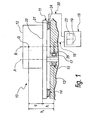
Figure 1 shows a simplified diagram of a part holder, according to the invention; -
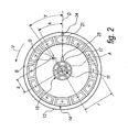
Figure 2 shows a simplified diagram of a part holder, according to the invention, without the worktable and seen in a plan view from above; -
Figures 3 and4 show two flowcharts of the functioning of a part holder, according to the invention; -
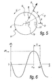
Figure 5 shows a simplified diagram of a part holder, according to the invention, in a plan view seen from above; -
Figure 6 shows a chart of the trend of one of the parameters as a function of the rotation angle of the worktable on the footing of a part holder, according to the invention, in non-balanced load conditions. - It should be noted that everything found to be already known during the patenting procedure is not intended to be claimed and is intended to be removed from the claims.
- With reference to the figures, the
reference numeral 10 generally designates a part holder, particularly for parts having a large mass to be machined in machine tools such as vertical lathes and the like, which comprises - a
worktable 11 for supporting thepart 12 to be machined, - a
footing 13 for supporting theworktable 11, - an axial bearing 14 which is adapted to support the
worktable 11 on thefooting 13, - a
radial bearing 15, provided with hydrostatic radial sliders, which is adapted for the guided coupling of theworktable 11 with thefooting 13 so as to allow rotation about a rotation axis A of theworktable 11 on thefooting 13, the rotation axis A being formed by the axis of theradial bearing 15, - first sensing means 16, which are functionally connected to a chosen
radial slider 17 of the radial bearing 15 and are adapted to detect a functional parameter, such functional parameter being a parameter which indicates the operation of the chosenradial slider 17, such as for example the operating pressure or the gap height, - a
central processing unit 18, which is functionally connected to the sensing means 16 in order to receive from them estimates of the functional parameter. - The
central processing unit 18 comprises means 19 for estimating the eccentricity E of the centre of gravity axis B, of apart 12 arranged on theworktable 11, with respect to the rotation axis A, the estimation means 19 being adapted to process the values of such functional parameter detected by the sensing means 16, so as to obtain the value of the eccentricity E, to be indicated to the operator. - In a substantially equivalent manner, other embodiments of a part holder, according to the invention, can comprise more than one axial bearing and/or more than one radial bearing.
- Advantageously, the axial bearing 14 comprises axial sliders with hydrostatic support.
- Moreover, the
part holder 10 advisably comprises second sensing means 20, which are functionally connected to a chosenradial slider 21 of theradial bearing 14, in order to detect a functional parameter thereof, which is a parameter that indicates its operation, such as for example the operating pressure or the gap height. - The
central processing unit 18 conveniently is functionally connected to the second sensing means 20 in order to receive from them estimates of such functional parameter. - Moreover, preferably, the
central processing unit 18 also comprisesmeans 22 for estimating the height q, on theworktable 11, of the centre of gravity G of apart 12 which is arranged on theresting surface 23 of theworktable 11. - The estimation means 22 are advisably adapted to process the values of the functional and operating parameters that are detected by the
sensing means 16 and 20, so as to obtain the value of the height q. - In alternative embodiments of the invention, the second sensing means can be connected to more than one chosen axial slider, in order to detect possibly more than one operating parameter thereof, as well as the first sensing means can be connected to more than one chosen radial slider, in order to detect possibly more than one functional parameter thereof.
- In substantially equivalent embodiments of the part holder, according to the invention, not shown in the accompanying drawings, such axial bearings and/or such radial bearings conveniently comprise
- a bearing with rolling elements, such as balls or rollers, and
- hydrostatic sliders, which are interposed between such bearing with rolling elements and at least one of the components of the part holder, chosen between the worktable and the footing, which the bearing with rolling elements rotatably couples to the other.
- In such embodiments, such hydrostatic sliders are substantially static with respect to the elements between which they are interposed, since they are interposed between a race of the bearing with rolling elements and the component of the part holder which remains substantially integral with such race.
- Preferably, the second sensing means 20 comprise a
first pressure transducer 24, which is connected to the chosenaxial slider 21, in order to detect an axial flow pressure P1, this being the operating pressure of the chosenaxial slider 21, such operating parameter being the axial flow pressure P1. - Moreover, conveniently, the first sensing means 16 also comprise at least a
second pressure transducer 25, which is connected to the chosenaxial slider 17, in order to detect a radial flow pressure P2, this being the operating pressure of the chosenaxial slider 17, and such operating parameter thus being the radial flow pressure P2. - Moreover, the
central processing unit 18 advantageously comprises load calculation means, which are adapted to calculate the value of the load m that bears on theworktable 11, the value of the load m being equal to the product obtained by multiplying a value of a stationary axial pressure variation dPo multiplied by a first virtual area Av1 multiplied by the number of sliders n1 of the axial bearing 21, i.e. in formula m=dP0·Av1·n1, where the first virtual area Av1 is the virtual area of the chosenaxial slider 21 and the stationary axial pressure variation dPo is equal to the pressure variation detected by thefirst pressure transducer 24 between a condition in which theworktable 11 is stationary and not loaded and a condition in which theworktable 11 is stationary and loaded with such load, i.e. with thepart 12 and any other masses of auxiliary bodies. - Preferably, the estimation means 19 comprise
- recording means, which are adapted to perform an operation C for recording values of a rotation angle x, of the value of the load m and of values of the radial flow pressure P2 as a function of the rotation angle x, which is the rotation angle of the
worktable 11 around the axis of rotation A with respect to a predefined reference D, - first calculation means, which are adapted to perform a first operation H for calculating the value of a maximum radial flow pressure variation dP2max and of a maximum pressure angle xmax, the maximum radial flow pressure variation value dP2max being equal to the maximum value assumed by the variation of the radial flow pressure P2 detected by the
second pressure transducer 25 in an interval of values of the rotation angle x that covers 360° and which thus corresponds to a complete rotation of theworktable 11 performed at a chosen constant angular velocity v, and the maximum pressure angle xmax being the value assumed by the rotation angle x for which the radial flow pressure variation dP2 is equal to the maximum radial flow pressure variation dP2max, - second calculation means, which are adapted to perform a second operation L for calculating a value of an angle of the load y and a value of the force of the load F, the load angle y being equal to the difference obtained by subtracting from 360° the value of the maximum pressure angle amax expressed in degrees, i.e. in formula y°=360°-amax°, the load force value F being further equal to the product of the multiplication of half of the number of sliders n2 of the
radial bearing 15 multiplied by a second virtual area Av2 multiplied by the maximum radial flow pressure variation dP2max, i.e. in formula F=(n2/2)·Av2·dP2max, where the second virtual area Av2 is the virtual area of the chosenradial slider 17, - third calculation means, which are adapted to perform a third operation N for calculating the value of eccentricity E, which is equal to the ratio that is the result of the division of the force of the load F divided by the product of such value of the load m multiplied by the square of the value of such chosen angular velocity v, in formula E=F/(m·v2).
- It is noted that the validity of the formula for calculating the load force F, i.e. F=(n2/2)·Av2·dP2max, is easily found and confirmed in the current state of the art.
- Indeed, it is sufficient to carry out a test which is adapted to detect the pressure on each radial slider during the constant-speed rotation of a worktable which is supporting a load with a centre of gravity axis that is eccentric with respect to the axis of rotation of the worktable, in order to find that the centrifugal force due to this eccentricity, which is detected as the composition of the stresses that are cooperatively supported by the radial sliders, can effectively be approximated with such calculation formula.
- Conveniently, the recording means are further adapted to perform an auxiliary recording operation Q of values of the axial flow pressure P1 as a function of the rotation angle x.
- Moreover, the estimation means 22 advantageously comprise
- fourth calculation means, which are adapted to perform a fourth operation R for calculating a value of maximum axial flow pressure variation dP1max equal to the maximum value assumed by the variation of the axial flow pressure P1 detected by the
first pressure transducer 24 in a range of values of the rotation angle x which covers 360°, i.e. corresponding to a complete rotation of theworktable 11 performed at the chosen constant angular velocity v, - fifth calculation means, which are adapted to perform a fifth operation T for calculating a value of tipping moment MF equal to the product that is the result of the multiplication of the first virtual area Av1 multiplied by such maximum axial flow pressure variation dP1max divided by a distribution coefficient s, in formula MF=Av1·dP1max/s, the distribution coefficient s being equal to the reciprocal of the product obtained from the multiplication of the radius of the sliders r multiplied by the sum obtained by adding the squares of the cosines of the angles of the centres of the sliders ai, estimated with respect to a reference radius, in formula

- sixth calculation means, which are adapted to perform a sixth operation U for calculating the height q equal to the difference between a height of the centre of gravity hg and a height of the worktable ht, in formula q=hg-ht, the height of the centre of gravity hg being equal to the ratio obtained from the division of the value of the tipping moment MF divided by the force of the load F, in formula hg=MF/F, and such height of the worktable ht being equal to the distance between the centre of the
radial bearing 15 and the restingsurface 23 of theworktable 11. , - It is noted that the distribution coefficient s is an estimate of the distribution of the eccentric stress with respect to the axis of rotation of the worktable that is supported during the operation by the sliders of a hydrostatic bearing.
- The validity of the expression of the distribution coefficient s offered here, i.e.

is easily found and confirmed in the current state of the art. - Indeed, it is sufficient to carry out a test which is adapted to detect the pressure on each axial slider during the constant-speed rotation of the worktable which is supporting a load with a centre of gravity axis that is eccentric with respect to the axis of rotation of the worktable, in order to find that the distribution of the stresses that are supported by the axial sliders can be reasonably approximated to that calculated with this expression.
- Advantageously, the
central processing unit 18 is an electronic computer, such as for example a PLC (which is the acronym of the English expression "programmable logic controller"), which integrates the recording means and the calculation means. - Moreover, the
central processing unit 18 comprises means for interfacing with the operator, which are not shown in the enclosed drawings and which can for example be implemented with a monitor connected to the PLC, which are adapted to display - the value of the maximum pressure angle xmax, with respect to the reference D,
- the value of the eccentricity E, and
- the value of the height q.
- With these indications the operator is able to estimate the mass and position of the counterweight or counterweights in order to obtain an exact and safe balancing of the
part holder 10. - Advantageously, the
central processing unit 18 further comprises seventh calculation means, for calculating a counterweight mass and a position of such counterweight mass on theworktable 11, for the balancing of thepart 12 on theworktable 11, the term balancing here meaning that condition corresponding to a configuration in which the eccentricity E, estimated as described above, has a nil value. - The operation of a
part holder 10, according to the invention, is as follows. - A
part 12 to be machined is arranged on theworktable 11 in a chosen position for machining, and is locked in place by the provided claws, which are not shown in the accompanying figures. - The piece is now ready for the balancing operation.
- With the worktable stationary, such load calculation means estimate the value of the load m that bears on the
worktable 11, which is given by m=dP0·Av1·n1), according to the foregoing description. - In this way the
part holder 10 is also an instrument for the weighing of the parts arranged on itsworktable 11. - In order to assess the eccentricity E (if any) of the centre of gravity axis B of the load with respect to the axis of rotation A, the
worktable 11 is made to rotate at the chosen angular velocity v. - For the purposes of non-limiting example, with reference to
Figure 5 , therein the letter Z indicates a reference radius which is integral with theworktable 11. - The angle of rotation x is assumed, which is equal to the angle comprised between the reference radius Z and the reference D which is integral with the
footing 13. - With particular reference to
Figure 3 , the estimation means 19, on the basis of the readings of thesecond pressure transducer 25, perform the estimate of the eccentricity E by means of - the first calculation means, which perform a first calculation operation H, of the value of the maximum radial flow pressure variation dP2max and of the maximum pressure angle xmax,
- the second calculation means, which perform a second calculation operation L, of the value of an angle of the load y°=360°-xmax°, and of a value of the force of the load F=(n2/2)·Av2·dP2max, and
- the third calculation means, which perform a third calculation operation N, of the value of eccentricity E=F/(m·v2).
- In this way, the operator has an indication that the centre of gravity axis B can be identified on the
worktable 11 - at a distance which is equal to the eccentricity E of the axis of rotation A, and
- in an angular position, with respect to the reference radius Z, that is equal to the angle of the load y, measured in the direction of the chosen angular velocity v.
- At this point the operator can carry out a first balancing by means of the positioning of counterweights on the
worktable 11. - In order to also implement a balancing which is aimed at cancelling out the tipping moment of the load in the working configuration, the estimation means 22, by means of processing the operating parameter detected by the
first pressure transducer 24, estimate the height q of the centre of gravity G on the restingsurface 23. - More specifically, the estimation means 22 perform the estimation of the height q by means of
- the fourth calculation means, which perform a fourth calculation operation R, of the value of the maximum axial flow pressure variation dP1max,
- the fifth calculation means, which perform a fifth calculation operation T, of the value of the tipping moment MF=Av1·dP1max/s,
- the sixth calculation means, which perform a sixth calculation operation U, of the height q=hg-ht.
- Advisably, then such seventh calculation means calculate, for the operator, the value of a counterweight mass and its position on the
worktable 11, for the balancing of thepart 12 on theworktable 11. - In practice it has been found that the invention fully achieves the intended aim and objects by devising a part holder that makes it possible to precisely and effectively balance the load being supported by the worktable for the machining of the part arranged upon it.
- Moreover, a part holder according to the invention makes it possible to identify, and indicate to the operator, the position of the centre of gravity axis of the load supported by the worktable with respect to the axis of rotation of the worktable, and thus promptly indicate anomalous load conditions to the operator.
- A part holder according to the invention also makes it possible to identify and indicate, to the operator, the height on the worktable of the centre of gravity of the load that it is supporting, so that the tipping moment that the part may experience during the machining, if there is any eccentricity of its centre of gravity axis with respect to the axis of rotation, may be balanced in a straightforward manner.
- Also, a part holder according to the invention makes it possible to identify, and indicate to the operator, the position of the centre of gravity axis and/or of the height of the centre of gravity of the load supported by the worktable, in a reliable and efficient manner, using the estimate of the pressure of the sliders of the hydrostatic bearings.
Claims (11)
- A part holder (10) particularly for parts having a large mass to be machined in machine tools such as vertical lathes and the like, comprising- a worktable (11) for supporting a part (12) to be machined,- a footing (13) for supporting said worktable (11),- at least one axial bearing (14), which is adapted to support said worktable (11) on said footing (13); and- a central processing unit (18) comprising means (19) for estimating the eccentricity of the centre of gravity axis (B) of a part (12) arranged on said worktable (11) with respect to a rotation axis (A) of said worktable (11),
the part holder (10) being characterized in that it further comprises- at least one radial bearing (15), provided with hydrostatic radial sliders, which is adapted for the guided coupling of said worktable (11) with said footing (13) so as to allow rotation about said rotation axis (A) of said worktable (11) on said footing (13), said rotation axis (A) being formed by the axis of said radial bearing (15), and- first sensing means (16), which are functionally connected to at least one chosen radial slider (17) of said at least one radial bearing (15) and are adapted to detect at least one functional parameter, said at least one functional parameter being a parameter that indicates the operation of said at least one chosen radial slider (17),- said central processing unit (18) being functionally connected to said first sensing means (16) in order to receive from them estimates of said functional parameter, and said estimation means (19) being adapted to process the values of said functional parameter detected by said sensing means (16), so as to obtain the value of said eccentricity (E). - The part holder according to claim 1, characterized in that said axial bearing (14) comprises axial sliders with hydrostatic support, said part holder (10) further comprising second sensing means (20), which are functionally connected to at least one chosen axial slider (21) of said axial bearing (14) and are adapted to detect at least one operating parameter, said at least one operating parameter being a parameter that indicates the operation of said at least one chosen axial slider (21), said central processing unit (18) being further functionally connected to second sensing means (20) in order to receive from them estimates of said operating parameter, said central processing unit (18) further comprising means (22) for assessing the height (q), on said worktable (11), of the centre of gravity (G) of a part (12) arranged on the resting surface (23) of said worktable (11), said assessment means (22) being adapted to process said values of said parameters detected by said first and second sensing means (16, 20), so as to obtain the value of said height (q).
- The part holder according to claim 2, characterized in that said second sensing means (20) comprise at least one first pressure transducer (24), which is connected to said at least one chosen axial slider (21), in order to detect an axial flow pressure (P1), which is the operating pressure of said at least one chosen axial slider (21), said at least one operating parameter comprising said axial flow pressure (P1).
- The part holder according to claim 3, characterized in that said first sensing means (16) comprise at least one second pressure transducer (25), which is connected to said at least one chosen radial slider (17) in order to detect a radial flow pressure (P2), which is the operating pressure of said at least one chosen radial slider (17), said at least one functional parameter comprising said radial flow pressure (P2).
- The part holder according to claim 4, characterized in that said central processing unit (18) comprises load calculation means, which are adapted to calculate the value of the load (m) that bears on said worktable (11), said value of the load (m) being equal to the product obtained by multiplying a value of a stationary axial pressure variation (dP0) multiplied by a first virtual area (Av1) multiplied by the number of sliders of said axial bearing (14), in formulas m=dP0·Av1·n1, said stationary axial pressure variation (dP0) being equal to the pressure variation detected by said first pressure transducer (24) between a condition in which said worktable (11) is stationary and not loaded and a condition in which said worktable (11) is stationary and loaded with said load, and said first virtual area (Av1) being the virtual area of said chosen axial slider (21).
- The part holder according to claim 5, characterized in that said estimation means (19) comprise- recording means, which are adapted to perform an operation for recording (C) values of a rotation angle (a), of said value of the load (m) and of values of said radial flow pressure (P2) as a function of said rotation angle (a), said rotation angle (a) being the rotation angle of said worktable (11) around said axis of rotation (A) with respect to a predefined reference (D),- first calculation means, which are adapted to perform a first operation (H) for calculating a maximum radial flow pressure variation (dP2max) and a maximum pressure angle (xmax), said maximum radial flow pressure variation value (dP2max) being equal to the maximum value assumed by the variation of said radial flow pressure (P2) detected by said second pressure transducer (25) in an interval of values of said rotation angle (x) that covers 360° and corresponds to a rotation of said worktable (11) performed at a chosen constant angular velocity (v), and said maximum pressure angle (xmax) being the value assumed by said rotation angle (x) for which said radial flow pressure variation (dP2) is equal to said maximum radial flow pressure variation (dP2max),- second calculation means, which are adapted to perform a second operation (L) for calculating a value of an angle of the load (y) and a value of the force of the load (F), said load angle (y) being equal to the difference obtained by subtracting from 360° the value of said maximum pressure angle (xmax) expressed in degrees, in formula y°=360°-Xmax°, said load force value (F) being further equal to the product of the multiplication of half of the number of sliders (n2) of said radial bearing (15) multiplied by a second virtual area (Av2) multiplied by said maximum radial flow pressure variation (dP2max), in formula F=(n2/2)·Av2·dP2max, said second virtual area (Av2) being the virtual area of said chosen radial slider (17),- third calculation means, which are adapted to perform a third operation for calculating said value of eccentricity (E) equal to the ratio that is the result of the division of said force of the load (F) divided by the product of said value of the load (m) multiplied by the square of the value of said chosen angular velocity (v), in formula E=F/(m·v2).
- The part holder according to claim 6, characterized in that said recording means are further adapted to perform an auxiliary recording operation (Q) of values of said axial flow pressure (P1) as a function of said rotation angle (x), said assessment means (22) comprising- fourth calculation means, which are adapted to perform a fourth operation (R) for calculating a value of maximum axial flow pressure variation (dP1max) equal to the maximum value assumed by the variation of said axial flow pressure (P1) detected by said first pressure transducer (24) in a range of values of said rotation angle (x) which covers 360° and corresponds to a rotation of said worktable (11) performed at said chosen constant angular velocity (v),- fifth calculation means, which are adapted to perform a fifth operation (T) for calculating a value of tipping moment (MF) equal to the product that is the result of the multiplication of said first virtual area (Av1) multiplied by said maximum axial flow pressure variation (dP1max) divided by a distribution coefficient (s), in formula MF=Av1·dP1max/s, said distribution coefficient (s) being equal to the reciprocal of the product obtained from the multiplication of the radius of the sliders (r) multiplied by the sum obtained by adding the squares of the cosines of the angles of the centres of the sliders (ai), estimated with respect to a reference
radius, in formula - sixth calculation means, which are adapted to perform a sixth operation (U) for calculating said height (q) equal to the difference between a height of the centre of gravity (hg) and a height of the worktable (ht), in formula q=hg-ht , said height of the centre of gravity (hg) being equal to the ratio obtained from the division of said value of the tipping moment (MF) divided by said force of the load (F), in formula hg=MF/F, and said height of the worktable (ht) being equal to the distance between the centre of said radial bearing (15) and said resting surface (23) of said worktable (11).
 - The part holder according to claim 7, characterized in that said recording means and said calculation means are integrated in an electronic computer.
- The part holder according to claim 8, characterized in that said central processing unit (18) comprises means for interfacing with the operator, which are adapted to have at least- the value of said maximum pressure angle (xmax) with respect to said reference (D),- the value of said eccentricity (E), and- the value of said height (q).
- The part holder according to claim 9, characterized in that said central processing unit (18) comprises seventh means for calculating a counterweight mass and a position of said counterweight mass on said worktable (11), for the balancing of the part (12) on said worktable (11), said balancing corresponding to a configuration in which said eccentricity (E) has a nil value.
- The part holder according to one of the preceding claims, characterized in that at least one selectively between said at least one axial bearing and said at least one radial bearing comprises- a bearing with rolling elements, and- hydrostatic sliders, which are interposed between said bearing with rolling elements and at least one component of said part holder chosen between said worktable and said footing.
Applications Claiming Priority (2)
| Application Number | Priority Date | Filing Date | Title |
|---|---|---|---|
| IT000290A ITPD20090290A1 (en) | 2009-10-05 | 2009-10-05 | PIECE HOLDER PARTICULARLY FOR MASSES OF HIGH MASSES TO BE WORKED IN MACHINE TOOLS AS VERTICAL AND SIMILAR LATHES |
| PCT/EP2010/064850 WO2011042446A1 (en) | 2009-10-05 | 2010-10-05 | Part holder particularly for parts having a large mass to be machined in machine tools such as vertical lathes and the like |
Publications (2)
| Publication Number | Publication Date |
|---|---|
| EP2485866A1 EP2485866A1 (en) | 2012-08-15 |
| EP2485866B1 true EP2485866B1 (en) | 2013-09-11 |
Family
ID=42224816
Family Applications (1)
| Application Number | Title | Priority Date | Filing Date |
|---|---|---|---|
| EP10763182.2A Active EP2485866B1 (en) | 2009-10-05 | 2010-10-05 | Workpiece holder of a machine tool with means for estimating the eccentricity of the workpiece |
Country Status (4)
| Country | Link |
|---|---|
| EP (1) | EP2485866B1 (en) |
| ES (1) | ES2444568T3 (en) |
| IT (1) | ITPD20090290A1 (en) |
| WO (1) | WO2011042446A1 (en) |
Cited By (1)
| Publication number | Priority date | Publication date | Assignee | Title |
|---|---|---|---|---|
| CN105479192A (en) * | 2016-01-22 | 2016-04-13 | 武汉樵薪机械制造有限公司 | Oil supply type static-pressure rectification system for support platform |
Families Citing this family (3)
| Publication number | Priority date | Publication date | Assignee | Title |
|---|---|---|---|---|
| DE102012110621B3 (en) * | 2012-11-06 | 2013-11-21 | Schenck Rotec Gmbh | Method and device for determining the static imbalance |
| CN110514440B (en) * | 2019-08-12 | 2024-02-23 | 德清恒丰机械股份有限公司 | Special-shaped bearing precision detection tool for vehicle |
| CN115673783B (en) * | 2022-11-02 | 2023-09-12 | 武汉重型机床集团有限公司 | Method and system for detecting and compensating unbalance of machining part of static pressure workbench |
Family Cites Families (3)
| Publication number | Priority date | Publication date | Assignee | Title |
|---|---|---|---|---|
| JPS5225910B2 (en) * | 1971-09-14 | 1977-07-11 | ||
| GB2160451B (en) * | 1984-05-25 | 1987-07-08 | Citizen Watch Co Ltd | A rotary table unit |
| ITMO20070374A1 (en) * | 2007-12-06 | 2009-06-07 | Pama Spa | SYSTEM AND METHOD TO FOOD WITH FLUID IN PRESSURE HYDROSTATIC ROTARY TABLES |
-
2009
- 2009-10-05 IT IT000290A patent/ITPD20090290A1/en unknown
-
2010
- 2010-10-05 WO PCT/EP2010/064850 patent/WO2011042446A1/en not_active Ceased
- 2010-10-05 ES ES10763182.2T patent/ES2444568T3/en active Active
- 2010-10-05 EP EP10763182.2A patent/EP2485866B1/en active Active
Cited By (1)
| Publication number | Priority date | Publication date | Assignee | Title |
|---|---|---|---|---|
| CN105479192A (en) * | 2016-01-22 | 2016-04-13 | 武汉樵薪机械制造有限公司 | Oil supply type static-pressure rectification system for support platform |
Also Published As
| Publication number | Publication date |
|---|---|
| WO2011042446A1 (en) | 2011-04-14 |
| ITPD20090290A1 (en) | 2011-04-06 |
| EP2485866A1 (en) | 2012-08-15 |
| ES2444568T3 (en) | 2014-02-25 |
Similar Documents
| Publication | Publication Date | Title |
|---|---|---|
| US9671210B2 (en) | Method for determining a correction value for the monitoring of a fluid bearing and machine having at least one fluid bearing | |
| CN104122036B (en) | Routine test centrifuge stationary-mobile state balance monitoring device | |
| CN106885736B (en) | A testing system for the dynamic stiffness performance of a spindle rotor | |
| US11609150B2 (en) | Test stand and method for testing a bearing | |
| CN110231171B (en) | A hydrostatic rotary test bench | |
| CN109465679A (en) | A kind of rail traffic high-precision bearing production technology | |
| CN111673644B (en) | Device and method for testing rigidity of grinding spindle | |
| US7392701B2 (en) | Balancing machine | |
| WO2011042446A1 (en) | Part holder particularly for parts having a large mass to be machined in machine tools such as vertical lathes and the like | |
| CN105424279B (en) | The method for detecting bearing retainer unbalancing value | |
| CN110849624A (en) | Main shaft radial loading device and machine tool main shaft performance testing method | |
| CN105458744A (en) | Quantitative and constant-pressure type hydrostatic pressure rotary table experimental device | |
| CN112834114A (en) | A high-speed dynamic balancing machine supporting swing frame | |
| CN110411634B (en) | Device and method for measuring grinding force of spherical basal plane of conical roller | |
| CN210625623U (en) | Novel parallelism detector | |
| CN202032254U (en) | Rotary bearing unit with measurement and control device | |
| CN116765954B (en) | Eccentricity calibration system for crankshaft grinding machines | |
| CN105699083A (en) | A modularization main shaft comprehensive properties test system | |
| CN102513834B (en) | Method for assembling high-precision rotary worktable of vertical milling-turning center | |
| CN115673783B (en) | Method and system for detecting and compensating unbalance of machining part of static pressure workbench | |
| CN214373118U (en) | High-speed dynamic balancing machine supporting swing frame | |
| GB744662A (en) | Improvements in or connected with balance centreing apparatus associated with means for drilling centreing holes on rotating bodies | |
| CN207300113U (en) | A kind of ultra-large type thrust ball split bearing is loaded and on-line measuring device | |
| CN120080113B (en) | A rounding machine | |
| CN107504884A (en) | Ultra-large type thrust ball split bearing is loaded and on-line measuring device |
Legal Events
| Date | Code | Title | Description |
|---|---|---|---|
| PUAI | Public reference made under article 153(3) epc to a published international application that has entered the european phase |
Free format text: ORIGINAL CODE: 0009012 |
|
| 17P | Request for examination filed |
Effective date: 20120427 |
|
| AK | Designated contracting states |
Kind code of ref document: A1 Designated state(s): AL AT BE BG CH CY CZ DE DK EE ES FI FR GB GR HR HU IE IS IT LI LT LU LV MC MK MT NL NO PL PT RO RS SE SI SK SM TR |
|
| DAX | Request for extension of the european patent (deleted) | ||
| GRAP | Despatch of communication of intention to grant a patent |
Free format text: ORIGINAL CODE: EPIDOSNIGR1 |
|
| INTG | Intention to grant announced |
Effective date: 20130402 |
|
| GRAS | Grant fee paid |
Free format text: ORIGINAL CODE: EPIDOSNIGR3 |
|
| GRAA | (expected) grant |
Free format text: ORIGINAL CODE: 0009210 |
|
| AK | Designated contracting states |
Kind code of ref document: B1 Designated state(s): AL AT BE BG CH CY CZ DE DK EE ES FI FR GB GR HR HU IE IS IT LI LT LU LV MC MK MT NL NO PL PT RO RS SE SI SK SM TR |
|
| REG | Reference to a national code |
Ref country code: GB Ref legal event code: FG4D |
|
| REG | Reference to a national code |
Ref country code: CH Ref legal event code: EP |
|
| REG | Reference to a national code |
Ref country code: AT Ref legal event code: REF Ref document number: 631344 Country of ref document: AT Kind code of ref document: T Effective date: 20130915 |
|
| REG | Reference to a national code |
Ref country code: IE Ref legal event code: FG4D |
|
| REG | Reference to a national code |
Ref country code: DE Ref legal event code: R096 Ref document number: 602010010249 Country of ref document: DE Effective date: 20131107 |
|
| PG25 | Lapsed in a contracting state [announced via postgrant information from national office to epo] |
Ref country code: CY Free format text: LAPSE BECAUSE OF FAILURE TO SUBMIT A TRANSLATION OF THE DESCRIPTION OR TO PAY THE FEE WITHIN THE PRESCRIBED TIME-LIMIT Effective date: 20130904 Ref country code: HR Free format text: LAPSE BECAUSE OF FAILURE TO SUBMIT A TRANSLATION OF THE DESCRIPTION OR TO PAY THE FEE WITHIN THE PRESCRIBED TIME-LIMIT Effective date: 20130911 Ref country code: NO Free format text: LAPSE BECAUSE OF FAILURE TO SUBMIT A TRANSLATION OF THE DESCRIPTION OR TO PAY THE FEE WITHIN THE PRESCRIBED TIME-LIMIT Effective date: 20131211 Ref country code: SE Free format text: LAPSE BECAUSE OF FAILURE TO SUBMIT A TRANSLATION OF THE DESCRIPTION OR TO PAY THE FEE WITHIN THE PRESCRIBED TIME-LIMIT Effective date: 20130911 Ref country code: LT Free format text: LAPSE BECAUSE OF FAILURE TO SUBMIT A TRANSLATION OF THE DESCRIPTION OR TO PAY THE FEE WITHIN THE PRESCRIBED TIME-LIMIT Effective date: 20130911 |
|
| REG | Reference to a national code |
Ref country code: NL Ref legal event code: VDEP Effective date: 20130911 |
|
| REG | Reference to a national code |
Ref country code: AT Ref legal event code: MK05 Ref document number: 631344 Country of ref document: AT Kind code of ref document: T Effective date: 20130911 |
|
| REG | Reference to a national code |
Ref country code: LT Ref legal event code: MG4D Ref country code: ES Ref legal event code: FG2A Ref document number: 2444568 Country of ref document: ES Kind code of ref document: T3 Effective date: 20140225 |
|
| PG25 | Lapsed in a contracting state [announced via postgrant information from national office to epo] |
Ref country code: FI Free format text: LAPSE BECAUSE OF FAILURE TO SUBMIT A TRANSLATION OF THE DESCRIPTION OR TO PAY THE FEE WITHIN THE PRESCRIBED TIME-LIMIT Effective date: 20130911 Ref country code: SI Free format text: LAPSE BECAUSE OF FAILURE TO SUBMIT A TRANSLATION OF THE DESCRIPTION OR TO PAY THE FEE WITHIN THE PRESCRIBED TIME-LIMIT Effective date: 20130911 Ref country code: GR Free format text: LAPSE BECAUSE OF FAILURE TO SUBMIT A TRANSLATION OF THE DESCRIPTION OR TO PAY THE FEE WITHIN THE PRESCRIBED TIME-LIMIT Effective date: 20131212 Ref country code: LV Free format text: LAPSE BECAUSE OF FAILURE TO SUBMIT A TRANSLATION OF THE DESCRIPTION OR TO PAY THE FEE WITHIN THE PRESCRIBED TIME-LIMIT Effective date: 20130911 |
|
| PG25 | Lapsed in a contracting state [announced via postgrant information from national office to epo] |
Ref country code: CY Free format text: LAPSE BECAUSE OF FAILURE TO SUBMIT A TRANSLATION OF THE DESCRIPTION OR TO PAY THE FEE WITHIN THE PRESCRIBED TIME-LIMIT Effective date: 20130911 Ref country code: BE Free format text: LAPSE BECAUSE OF FAILURE TO SUBMIT A TRANSLATION OF THE DESCRIPTION OR TO PAY THE FEE WITHIN THE PRESCRIBED TIME-LIMIT Effective date: 20130911 |
|
| PG25 | Lapsed in a contracting state [announced via postgrant information from national office to epo] |
Ref country code: NL Free format text: LAPSE BECAUSE OF FAILURE TO SUBMIT A TRANSLATION OF THE DESCRIPTION OR TO PAY THE FEE WITHIN THE PRESCRIBED TIME-LIMIT Effective date: 20130911 Ref country code: IS Free format text: LAPSE BECAUSE OF FAILURE TO SUBMIT A TRANSLATION OF THE DESCRIPTION OR TO PAY THE FEE WITHIN THE PRESCRIBED TIME-LIMIT Effective date: 20140111 Ref country code: EE Free format text: LAPSE BECAUSE OF FAILURE TO SUBMIT A TRANSLATION OF THE DESCRIPTION OR TO PAY THE FEE WITHIN THE PRESCRIBED TIME-LIMIT Effective date: 20130911 Ref country code: RO Free format text: LAPSE BECAUSE OF FAILURE TO SUBMIT A TRANSLATION OF THE DESCRIPTION OR TO PAY THE FEE WITHIN THE PRESCRIBED TIME-LIMIT Effective date: 20130911 Ref country code: CZ Free format text: LAPSE BECAUSE OF FAILURE TO SUBMIT A TRANSLATION OF THE DESCRIPTION OR TO PAY THE FEE WITHIN THE PRESCRIBED TIME-LIMIT Effective date: 20130911 Ref country code: SK Free format text: LAPSE BECAUSE OF FAILURE TO SUBMIT A TRANSLATION OF THE DESCRIPTION OR TO PAY THE FEE WITHIN THE PRESCRIBED TIME-LIMIT Effective date: 20130911 |
|
| PG25 | Lapsed in a contracting state [announced via postgrant information from national office to epo] |
Ref country code: PL Free format text: LAPSE BECAUSE OF FAILURE TO SUBMIT A TRANSLATION OF THE DESCRIPTION OR TO PAY THE FEE WITHIN THE PRESCRIBED TIME-LIMIT Effective date: 20130911 Ref country code: AT Free format text: LAPSE BECAUSE OF FAILURE TO SUBMIT A TRANSLATION OF THE DESCRIPTION OR TO PAY THE FEE WITHIN THE PRESCRIBED TIME-LIMIT Effective date: 20130911 |
|
| REG | Reference to a national code |
Ref country code: DE Ref legal event code: R097 Ref document number: 602010010249 Country of ref document: DE |
|
| PG25 | Lapsed in a contracting state [announced via postgrant information from national office to epo] |
Ref country code: PT Free format text: LAPSE BECAUSE OF FAILURE TO SUBMIT A TRANSLATION OF THE DESCRIPTION OR TO PAY THE FEE WITHIN THE PRESCRIBED TIME-LIMIT Effective date: 20140113 Ref country code: MC Free format text: LAPSE BECAUSE OF FAILURE TO SUBMIT A TRANSLATION OF THE DESCRIPTION OR TO PAY THE FEE WITHIN THE PRESCRIBED TIME-LIMIT Effective date: 20130911 |
|
| PLBE | No opposition filed within time limit |
Free format text: ORIGINAL CODE: 0009261 |
|
| STAA | Information on the status of an ep patent application or granted ep patent |
Free format text: STATUS: NO OPPOSITION FILED WITHIN TIME LIMIT |
|
| REG | Reference to a national code |
Ref country code: IE Ref legal event code: MM4A |
|
| 26N | No opposition filed |
Effective date: 20140612 |
|
| REG | Reference to a national code |
Ref country code: DE Ref legal event code: R097 Ref document number: 602010010249 Country of ref document: DE Effective date: 20140612 |
|
| PG25 | Lapsed in a contracting state [announced via postgrant information from national office to epo] |
Ref country code: DK Free format text: LAPSE BECAUSE OF FAILURE TO SUBMIT A TRANSLATION OF THE DESCRIPTION OR TO PAY THE FEE WITHIN THE PRESCRIBED TIME-LIMIT Effective date: 20130911 |
|
| PG25 | Lapsed in a contracting state [announced via postgrant information from national office to epo] |
Ref country code: IE Free format text: LAPSE BECAUSE OF NON-PAYMENT OF DUE FEES Effective date: 20131005 |
|
| PG25 | Lapsed in a contracting state [announced via postgrant information from national office to epo] |
Ref country code: SM Free format text: LAPSE BECAUSE OF FAILURE TO SUBMIT A TRANSLATION OF THE DESCRIPTION OR TO PAY THE FEE WITHIN THE PRESCRIBED TIME-LIMIT Effective date: 20130911 |
|
| REG | Reference to a national code |
Ref country code: CH Ref legal event code: PL |
|
| GBPC | Gb: european patent ceased through non-payment of renewal fee |
Effective date: 20141005 |
|
| PG25 | Lapsed in a contracting state [announced via postgrant information from national office to epo] |
Ref country code: CH Free format text: LAPSE BECAUSE OF NON-PAYMENT OF DUE FEES Effective date: 20141031 Ref country code: RS Free format text: LAPSE BECAUSE OF FAILURE TO SUBMIT A TRANSLATION OF THE DESCRIPTION OR TO PAY THE FEE WITHIN THE PRESCRIBED TIME-LIMIT Effective date: 20131211 Ref country code: LU Free format text: LAPSE BECAUSE OF NON-PAYMENT OF DUE FEES Effective date: 20131005 Ref country code: LI Free format text: LAPSE BECAUSE OF NON-PAYMENT OF DUE FEES Effective date: 20141031 Ref country code: BG Free format text: LAPSE BECAUSE OF FAILURE TO SUBMIT A TRANSLATION OF THE DESCRIPTION OR TO PAY THE FEE WITHIN THE PRESCRIBED TIME-LIMIT Effective date: 20130911 Ref country code: HU Free format text: LAPSE BECAUSE OF FAILURE TO SUBMIT A TRANSLATION OF THE DESCRIPTION OR TO PAY THE FEE WITHIN THE PRESCRIBED TIME-LIMIT; INVALID AB INITIO Effective date: 20101005 Ref country code: GB Free format text: LAPSE BECAUSE OF NON-PAYMENT OF DUE FEES Effective date: 20141005 Ref country code: MK Free format text: LAPSE BECAUSE OF FAILURE TO SUBMIT A TRANSLATION OF THE DESCRIPTION OR TO PAY THE FEE WITHIN THE PRESCRIBED TIME-LIMIT Effective date: 20130911 |
|
| PG25 | Lapsed in a contracting state [announced via postgrant information from national office to epo] |
Ref country code: MT Free format text: LAPSE BECAUSE OF FAILURE TO SUBMIT A TRANSLATION OF THE DESCRIPTION OR TO PAY THE FEE WITHIN THE PRESCRIBED TIME-LIMIT Effective date: 20130911 |
|
| REG | Reference to a national code |
Ref country code: FR Ref legal event code: PLFP Year of fee payment: 6 |
|
| PG25 | Lapsed in a contracting state [announced via postgrant information from national office to epo] |
Ref country code: TR Free format text: LAPSE BECAUSE OF FAILURE TO SUBMIT A TRANSLATION OF THE DESCRIPTION OR TO PAY THE FEE WITHIN THE PRESCRIBED TIME-LIMIT Effective date: 20130911 |
|
| REG | Reference to a national code |
Ref country code: FR Ref legal event code: PLFP Year of fee payment: 7 |
|
| REG | Reference to a national code |
Ref country code: FR Ref legal event code: PLFP Year of fee payment: 8 |
|
| PGFP | Annual fee paid to national office [announced via postgrant information from national office to epo] |
Ref country code: FR Payment date: 20171027 Year of fee payment: 8 Ref country code: DE Payment date: 20171124 Year of fee payment: 8 |
|
| PGFP | Annual fee paid to national office [announced via postgrant information from national office to epo] |
Ref country code: ES Payment date: 20171124 Year of fee payment: 8 |
|
| PG25 | Lapsed in a contracting state [announced via postgrant information from national office to epo] |
Ref country code: AL Free format text: LAPSE BECAUSE OF FAILURE TO SUBMIT A TRANSLATION OF THE DESCRIPTION OR TO PAY THE FEE WITHIN THE PRESCRIBED TIME-LIMIT Effective date: 20130911 |
|
| REG | Reference to a national code |
Ref country code: DE Ref legal event code: R119 Ref document number: 602010010249 Country of ref document: DE |
|
| PG25 | Lapsed in a contracting state [announced via postgrant information from national office to epo] |
Ref country code: DE Free format text: LAPSE BECAUSE OF NON-PAYMENT OF DUE FEES Effective date: 20190501 |
|
| PG25 | Lapsed in a contracting state [announced via postgrant information from national office to epo] |
Ref country code: FR Free format text: LAPSE BECAUSE OF NON-PAYMENT OF DUE FEES Effective date: 20181031 |
|
| REG | Reference to a national code |
Ref country code: ES Ref legal event code: FD2A Effective date: 20191129 |
|
| PG25 | Lapsed in a contracting state [announced via postgrant information from national office to epo] |
Ref country code: ES Free format text: LAPSE BECAUSE OF NON-PAYMENT OF DUE FEES Effective date: 20181006 |
|
| P01 | Opt-out of the competence of the unified patent court (upc) registered |
Effective date: 20230714 |
|
| PGFP | Annual fee paid to national office [announced via postgrant information from national office to epo] |
Ref country code: IT Payment date: 20251022 Year of fee payment: 16 |