EP2485865B1 - Part holder for machine tool with preloading of a hydrostatic supporting bearing - Google Patents
Part holder for machine tool with preloading of a hydrostatic supporting bearing Download PDFInfo
- Publication number
- EP2485865B1 EP2485865B1 EP10760711.1A EP10760711A EP2485865B1 EP 2485865 B1 EP2485865 B1 EP 2485865B1 EP 10760711 A EP10760711 A EP 10760711A EP 2485865 B1 EP2485865 B1 EP 2485865B1
- Authority
- EP
- European Patent Office
- Prior art keywords
- preloading
- bearing
- pressure
- variation
- supporting
- Prior art date
- Legal status (The legal status is an assumption and is not a legal conclusion. Google has not performed a legal analysis and makes no representation as to the accuracy of the status listed.)
- Active
Links
Images


Classifications
-
- B—PERFORMING OPERATIONS; TRANSPORTING
- B23—MACHINE TOOLS; METAL-WORKING NOT OTHERWISE PROVIDED FOR
- B23Q—DETAILS, COMPONENTS, OR ACCESSORIES FOR MACHINE TOOLS, e.g. ARRANGEMENTS FOR COPYING OR CONTROLLING; MACHINE TOOLS IN GENERAL CHARACTERISED BY THE CONSTRUCTION OF PARTICULAR DETAILS OR COMPONENTS; COMBINATIONS OR ASSOCIATIONS OF METAL-WORKING MACHINES, NOT DIRECTED TO A PARTICULAR RESULT
- B23Q1/00—Members which are comprised in the general build-up of a form of machine, particularly relatively large fixed members
- B23Q1/25—Movable or adjustable work or tool supports
- B23Q1/26—Movable or adjustable work or tool supports characterised by constructional features relating to the co-operation of relatively movable members; Means for preventing relative movement of such members
- B23Q1/38—Movable or adjustable work or tool supports characterised by constructional features relating to the co-operation of relatively movable members; Means for preventing relative movement of such members using fluid bearings or fluid cushion supports
- B23Q1/385—Movable or adjustable work or tool supports characterised by constructional features relating to the co-operation of relatively movable members; Means for preventing relative movement of such members using fluid bearings or fluid cushion supports in which the thickness of the fluid-layer is adjustable
-
- B—PERFORMING OPERATIONS; TRANSPORTING
- B23—MACHINE TOOLS; METAL-WORKING NOT OTHERWISE PROVIDED FOR
- B23Q—DETAILS, COMPONENTS, OR ACCESSORIES FOR MACHINE TOOLS, e.g. ARRANGEMENTS FOR COPYING OR CONTROLLING; MACHINE TOOLS IN GENERAL CHARACTERISED BY THE CONSTRUCTION OF PARTICULAR DETAILS OR COMPONENTS; COMBINATIONS OR ASSOCIATIONS OF METAL-WORKING MACHINES, NOT DIRECTED TO A PARTICULAR RESULT
- B23Q11/00—Accessories fitted to machine tools for keeping tools or parts of the machine in good working condition or for cooling work; Safety devices specially combined with or arranged in, or specially adapted for use in connection with, machine tools
- B23Q11/001—Arrangements compensating weight or flexion on parts of the machine
- B23Q11/0028—Arrangements compensating weight or flexion on parts of the machine by actively reacting to a change of the configuration of the machine
-
- F—MECHANICAL ENGINEERING; LIGHTING; HEATING; WEAPONS; BLASTING
- F16—ENGINEERING ELEMENTS AND UNITS; GENERAL MEASURES FOR PRODUCING AND MAINTAINING EFFECTIVE FUNCTIONING OF MACHINES OR INSTALLATIONS; THERMAL INSULATION IN GENERAL
- F16C—SHAFTS; FLEXIBLE SHAFTS; ELEMENTS OR CRANKSHAFT MECHANISMS; ROTARY BODIES OTHER THAN GEARING ELEMENTS; BEARINGS
- F16C32/00—Bearings not otherwise provided for
- F16C32/06—Bearings not otherwise provided for with moving member supported by a fluid cushion formed, at least to a large extent, otherwise than by movement of the shaft, e.g. hydrostatic air-cushion bearings
- F16C32/0629—Bearings not otherwise provided for with moving member supported by a fluid cushion formed, at least to a large extent, otherwise than by movement of the shaft, e.g. hydrostatic air-cushion bearings supported by a liquid cushion, e.g. oil cushion
- F16C32/064—Bearings not otherwise provided for with moving member supported by a fluid cushion formed, at least to a large extent, otherwise than by movement of the shaft, e.g. hydrostatic air-cushion bearings supported by a liquid cushion, e.g. oil cushion the liquid being supplied under pressure
- F16C32/0644—Details of devices to control the supply of liquids to the bearings
- F16C32/0648—Details of devices to control the supply of liquids to the bearings by sensors or pressure-responsive control devices in or near the bearings
-
- F—MECHANICAL ENGINEERING; LIGHTING; HEATING; WEAPONS; BLASTING
- F16—ENGINEERING ELEMENTS AND UNITS; GENERAL MEASURES FOR PRODUCING AND MAINTAINING EFFECTIVE FUNCTIONING OF MACHINES OR INSTALLATIONS; THERMAL INSULATION IN GENERAL
- F16C—SHAFTS; FLEXIBLE SHAFTS; ELEMENTS OR CRANKSHAFT MECHANISMS; ROTARY BODIES OTHER THAN GEARING ELEMENTS; BEARINGS
- F16C32/00—Bearings not otherwise provided for
- F16C32/06—Bearings not otherwise provided for with moving member supported by a fluid cushion formed, at least to a large extent, otherwise than by movement of the shaft, e.g. hydrostatic air-cushion bearings
- F16C32/0681—Construction or mounting aspects of hydrostatic bearings, for exclusively rotary movement, related to the direction of load
- F16C32/0692—Construction or mounting aspects of hydrostatic bearings, for exclusively rotary movement, related to the direction of load for axial load only
-
- B—PERFORMING OPERATIONS; TRANSPORTING
- B23—MACHINE TOOLS; METAL-WORKING NOT OTHERWISE PROVIDED FOR
- B23Q—DETAILS, COMPONENTS, OR ACCESSORIES FOR MACHINE TOOLS, e.g. ARRANGEMENTS FOR COPYING OR CONTROLLING; MACHINE TOOLS IN GENERAL CHARACTERISED BY THE CONSTRUCTION OF PARTICULAR DETAILS OR COMPONENTS; COMBINATIONS OR ASSOCIATIONS OF METAL-WORKING MACHINES, NOT DIRECTED TO A PARTICULAR RESULT
- B23Q2220/00—Machine tool components
- B23Q2220/004—Rotary tables
-
- F—MECHANICAL ENGINEERING; LIGHTING; HEATING; WEAPONS; BLASTING
- F16—ENGINEERING ELEMENTS AND UNITS; GENERAL MEASURES FOR PRODUCING AND MAINTAINING EFFECTIVE FUNCTIONING OF MACHINES OR INSTALLATIONS; THERMAL INSULATION IN GENERAL
- F16C—SHAFTS; FLEXIBLE SHAFTS; ELEMENTS OR CRANKSHAFT MECHANISMS; ROTARY BODIES OTHER THAN GEARING ELEMENTS; BEARINGS
- F16C2322/00—Apparatus used in shaping articles
- F16C2322/39—General buildup of machine tools, e.g. spindles, slides, actuators
Definitions
- the present invention relates to a part holder for parts to be machined with machine tools, particularly for parts having a large mass to be machined in vertical lathes (see, for example, US-3,871,721 ).
- vertical lathes provided with a part holder which comprise rotating tables, provided with supporting fifth wheels with rolling bearings, i.e. roller bearings or ball race bearings, or hydrostatic bearings.
- a very pressing requirement in the field of these machines consists in ensuring a rigidity of the part holder, which makes it possible to prevent dynamic instabilities thereof when machining the parts, as the mass of the part to be machined changes.
- the dynamic behaviour of the devices designed in this way is therefore optimum for parts having weight that is equal to or nearly equal to the design load, while exhibiting a decrease in performance levels that is proportional to the difference in the weight of the part from that of the design load.
- hydrostatic bearings is particularly unsuitable for supporting the worktable-supporting fifth wheel in use in support devices upon which parts that vary greatly in weight are deployed.
- the reduction in the gap is a critical operating effect, in that, with the reduction in the operating gap, the probability of mutual contact of the hydrostatic sliders that make up the bearing increases.
- Compensation devices which are known today, which are used both in support devices with hydrostatic fifth wheels and in support devices with fifth wheels with rolling bearings, are adapted to determine a minimum operating load of the fifth wheel that supports, the worktable, or to cooperate with the fifth wheel in supporting the part, so limiting the maximum load weighing down on it.
- the most advanced compensation devices known today generally have hydraulic pistons on a preloading fifth wheel connected to the part-holder worktable.
- such devices extend the range of optimum operation of the part holder from one optimum load value to an interval of loads, acting on the bearings, which is equal to the interval of weights of the part for which they are adapted to compensate.
- the aim of the present invention is to meet this requirement, by devising a part holder that, in use, is in conditions of optimum operation substantially regardless of the weight of the part to be machined which it supports.
- an object of the invention is to provide a part holder that makes it possible to automatically modulate its configuration, as a function of the weight of the part that it supports, while maintaining its rigidity in conditions of optimum operation.
- Another object of the invention is to devise a part holder that makes it possible to automatically modulate its configuration while maintaining its rigidity in conditions of optimum operation even in the event of variations of loads which can be ascribed to heat expansions which arise during the machining of the part that it is supporting.
- Another object of the invention is to provide a part holder that makes it possible to automatically modulate its configuration even during the machining of the part that it is supporting.
- Another object of the invention is to devise a part holder that is structurally simple and easy to use.
- a part holder for parts to be machined with machine tools particularly for parts having a large mass to be machined in vertical lathes, characterized in that it comprises
- the reference numeral 10 generally indicates a part holder for parts to be machined with machine tools, particularly for parts having a large mass to be machined in vertical lathes, which comprises
- the central control unit 18 is functionally connected to the sensing means 17 so as to receive from them estimates of the functional parameter A, the central control unit 18 being further functionally connected to the modulation means 16 so as to drive them as a function of such estimates.
- hydrostatic bearing or hydrostatic support bearing, what is meant here is a bearing which is made up of a race of hydrostatic sliders.
- the part holder can comprise more than one supporting bearing and more than one preloading bearing, and furthermore, according to the contingent requirements, more than one functional parameter can be sensed by the sensing means, and possibly for more than one chosen supporting slider.
- the worktable 11 advantageously comprises a support 19, advisably annular, which is adapted to support the preloading bearing 15.
- the modulation means 16 conveniently comprise pistons 20 for pushing on the preloading bearing 15.
- the pistons 20 conveniently are functionally connected to the control unit 18 in order to be driven by it in setting the preloading thrust imparted to the supporting bearing 14, advisably by means of the preloading bearing 15.
- the sensing means 17 preferably comprise a pressure transducer 21 which is connected to the chosen supporting slider 14a, the pressure transducer 21 being adapted to estimate a flow pressure P 1 .
- flow pressure P 1 what is meant here is the operation pressure of the chosen supporting slider 14a.
- the functional parameter A is the flow pressure P 1 .
- the preloading bearing 15 can be with roller bearings, but preferably it is with hydrostatic support.
- the part holder 10 also comprises a supply system 22, for the hydraulic supply of the preloading bearing 15 to a pressure P 0 .
- the control unit 18, advisably, is functionally connected to the supply system 22 so as to drive the supply pressure of the preloading bearing 15 in tune with the simultaneous driving of the pistons 20.
- control unit 18 can perform the function of simultaneously driving the pistons 20 and the supply system 22 in order to compensate any variations in the load supported by the supporting bearing 14, if this load should tend to alter its operating condition thus distancing it from the condition of optimum operation.
- control unit 18 advantageously, comprises first calculation means which are adapted to calculate a variation of the preloading force dF p , to be applied to the supporting bearing 14 by means of the pistons 20, in order to compensate a variation in the load supported by it.
- the first virtual area A v1 is here understood to be the virtual area of the supporting bearing 14, and the optimum flow pressure P ott is the operating pressure of the supporting bearing 14 in the optimum functional condition.
- this pressure condition corresponds to an optimum gap height h 0 , of the supporting bearing 14.
- the part holder 10 adapts its configuration so that the gap height of the supporting bearing is equal to the optimum gap height h 0 , its operating pressure being equal to the optimum flow pressure P ott .
- optimum functional condition what is meant here is that functional condition of a hydrostatic bearing, identified by a pair of values of pressure P and of gap height h, which corresponds to the condition of maximum rigidity of the bearing.
- the variation of the pressure of the pistons dP p is the variation in the operating pressure of the pistons 20 which is adapted to impart the variation of the preloading force dF p to the supporting bearing 14.
- control unit 18 similarly and preferably comprises
- the second driving means advisably comprise at least one pressure servo-regulator which is interposed between the supply system 22 and the preloading bearing 15 so as to impart the supply pressure variation dP 0 which makes it possible to keep the gap height h of the preloading bearing 15 constant, to counteract the variation of the preloading pressure dP 2 .
- such pressure servo-regulator can impart the variation in the supply pressure dP 0 , of the preloading bearing 15 supplied by the supply system 22, so as to keep its gap height h constant to counteract the variation of the preloading pressure dP 2 .
- such calculation means and such driving means work according to a closed-loop cycle, determining cyclically and automatically
- such calculation means and such driving means operate according to an open cycle.
- the load supported by the supporting bearing 14 changes.
- This change is manifested as a variation in the flow pressure P 1 , which is detected by the pressure transducer 21, in the chosen supporting slider 14a.
- control unit 18 again receives the functional parameter A which is equal to the value of the updated flow pressure P 1 , detected by the pressure transducer 21, and the operations B, C, D and E are repeated cyclically.
- the part holder 10 automatically reacts by modulating the preloading force F p which acts upon it, in order to keep it in a condition of optimum operation.
- Figure 2a shows, for the purposes of non-limiting example, an operational condition of the preloading bearing 15, identified by the point at coordinates (h 2 , P 2 ) where the flow pressure P 2 corresponds to a gap height h which is equal to h 2 .
- control unit 18 reacts by imparting a variation of the supply pressure dP 0 which is such as to keep the gap height h constant, i.e. equal to h 2 , to counteract the variation of the preloading pressure dP 2 .
- the supporting bearing 14 is supplied by a supply circuit 23, which is adapted to determine its conditions of optimum operation which can be identified from an operating pressure which is equal to the optimum flow pressure P ott that corresponds to a gap height which is equal to an optimum gap height h 0 .
- control unit 18 modulates the supply pressure P 0 of the preloading bearing 15 so as to keep the gap height h of its sliders constant.
- a part holder 10 according to the invention is capable of offering is that of weighing the part 12 placed on the worktable 11. Since the weight force of the worktable M t is known, then the weight force of the part M p is equal to the difference resulting from the subtraction
- the part 12 in conditions of correct operation of a part holder 10 according to the invention, the part 12 must be balanced on the worktable 11, i.e., advisably by means of the use of counterweights, it must present its centre of gravity axis as coinciding with the machining axis, which is the axis of rotation of the worktable 11.
- a part holder according to the invention makes it possible to automatically modulate its configuration, as a function of the weight of the part that it supports, while maintaining its rigidity in conditions of optimum operation even in the event of variations of loads which can be ascribed to removal of shavings during the machining of the part that it is supporting.
- a part holder according to the invention makes it possible to automatically modulate its configuration during the machining of the piece that it is supporting, and is further structurally simple and easy to use.
Landscapes
- Engineering & Computer Science (AREA)
- General Engineering & Computer Science (AREA)
- Mechanical Engineering (AREA)
- Magnetic Bearings And Hydrostatic Bearings (AREA)
Description
- The present invention relates to a part holder for parts to be machined with machine tools, particularly for parts having a large mass to be machined in vertical lathes (see, for example,
US-3,871,721 ). - Nowadays, in the field of machine tools for machining parts having a large mass, for example even over 100 tonnes, vertical lathes provided with a part holder are known which comprise rotating tables, provided with supporting fifth wheels with rolling bearings, i.e. roller bearings or ball race bearings, or hydrostatic bearings.
- A very pressing requirement in the field of these machines consists in ensuring a rigidity of the part holder, which makes it possible to prevent dynamic instabilities thereof when machining the parts, as the mass of the part to be machined changes.
- Indeed, a requirement of the user of such lathes is to be able to use them for machining parts whose weight can vary from a few tonnes to 120 tonnes and more.
- On the other hand, nowadays the design philosophy followed for dimensioning the support devices in use today provide for the optimisation of the dynamic behaviour for a chosen load.
- The dynamic behaviour of the devices designed in this way is therefore optimum for parts having weight that is equal to or nearly equal to the design load, while exhibiting a decrease in performance levels that is proportional to the difference in the weight of the part from that of the design load.
- Fifth wheels with hydrostatic support bearings are today particularly appreciated because, for the same design conditions, compared to rolling bearings currently in use they do not have startup vacillations, which are due to the crushing of the rollers and of the balls, and they exhibit less absorption of power in the form of dynamic friction, and so exhibiting lower operating temperatures as well, all to the advantage of the dimensional stability of the parts that are sensitive to thermal dilatation effects.
- However, according to the design techniques indicated, the use of hydrostatic bearings is particularly unsuitable for supporting the worktable-supporting fifth wheel in use in support devices upon which parts that vary greatly in weight are deployed.
- Indeed, as is known, the optimum operation of hydrostatic bearings is identified by a gap thickness and fluid pressure which are dependent on the dimensioning choices.
- Therefore, a decrease in the load of such bearings, owing to the machining of a part having a lower weight than that of the design load, induces a reduction in the fluid pressure and an increase in the gap, which correspond to a rigidity configuration that is lower than that of the optimum operation and to a higher flow of fluid which the hydraulic system has to handle.
- Vice versa, overloading the hydrostatic bearing, with respect to the optimum load, induces an increase in rigidity which is correlated to the increase in fluid pressure and to the reduction in the gap.
- In particular, the reduction in the gap is a critical operating effect, in that, with the reduction in the operating gap, the probability of mutual contact of the hydrostatic sliders that make up the bearing increases.
- If such contact actually occurs, the damage to the fifth wheel is always extensive, whether it induces a sudden increase in the operating temperature, or, at worst, it causes the sliders to seize.
- So today, the use of hydrostatic fifth wheels, however appreciated they may be, tends to be relatively limited to machines which have a device for compensating the operating load.
- Compensation devices which are known today, which are used both in support devices with hydrostatic fifth wheels and in support devices with fifth wheels with rolling bearings, are adapted to determine a minimum operating load of the fifth wheel that supports, the worktable, or to cooperate with the fifth wheel in supporting the part, so limiting the maximum load weighing down on it.
- The most advanced compensation devices known today generally have hydraulic pistons on a preloading fifth wheel connected to the part-holder worktable.
- Such hydraulic pistons act
- in agreement with the weight of the part, in order to determine a gradual preloading on the load-bearing fifth wheel, or
- in disagreement with the weight of the part, in order to gradually share its support with the load-bearing fifth wheel, as the weight of the part to be supported increases.
- In effect, therefore, such compensating devices have an action on the load-bearing fifth wheel which is gradual in nature, pre-loading it or unloading it according to a pre-established proportionality to the weight to be supported.
- In this way, such devices extend the range of optimum operation of the part holder from one optimum load value to an interval of loads, acting on the bearings, which is equal to the interval of weights of the part for which they are adapted to compensate.
- Therefore, although they are much appreciated today, such compensating devices are however only capable of widening the field of optimum operation of the supporting devices on which they are fitted, which means that there is still a pressing need for supporting devices that can maintain an optimum rigidity by automatically adapting to the weight of the piece being machined, even if this should vary during the machining operation itself.
- The aim of the present invention is to meet this requirement, by devising a part holder that, in use, is in conditions of optimum operation substantially regardless of the weight of the part to be machined which it supports.
- Within this aim, an object of the invention is to provide a part holder that makes it possible to automatically modulate its configuration, as a function of the weight of the part that it supports, while maintaining its rigidity in conditions of optimum operation.
- Another object of the invention is to devise a part holder that makes it possible to automatically modulate its configuration while maintaining its rigidity in conditions of optimum operation even in the event of variations of loads which can be ascribed to heat expansions which arise during the machining of the part that it is supporting.
- Another object of the invention is to provide a part holder that makes it possible to automatically modulate its configuration even during the machining of the part that it is supporting.
- Another object of the invention is to devise a part holder that is structurally simple and easy to use.
- This aim, as well as these and other objects which will become better apparent hereinafter, are achieved by a part holder for parts to be machined with machine tools, particularly for parts having a large mass to be machined in vertical lathes, characterized in that it comprises
- a worktable for supporting the part,
- a footing for supporting said worktable,
- at least one hydrostatic supporting bearing, adapted to support said worktable on said footing,
- at least one preloading bearing, which is interposed between said worktable and said footing, in a dynamic parallel configuration with respect to said at least one supporting bearing,
- means for modulating a preloading imparted to said at least one supporting bearing,
- means for sensing at least one functional parameter of at least one chosen supporting slider of said at least one supporting bearing, and
- a central unit for controlling said modulation means,
- Further characteristics and advantages of the invention will become better apparent from the following detailed description of a preferred, but not exclusive, embodiment of the part holder according to the invention, illustrated by way of non-limiting example in the accompanying drawings, wherein:
-
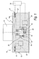
Figure 1 shows a simplified diagram of a part holder according to the invention; -
Figure 2a shows a chart of the general trend of the pressure as a function of the height of the gap in a hydrostatic bearing; -
Figure 2b shows a simplified general diagram of a hydrostatic bearing; -
Figure 3 shows a flowchart of the functioning of a part holder, according to the invention. - It should be noted that everything found to be already known during the patenting procedure is not intended to be claimed and is intended to be removed from the claims.
- With reference to the figures, the
reference numeral 10 generally indicates a part holder for parts to be machined with machine tools, particularly for parts having a large mass to be machined in vertical lathes, which comprises - a
worktable 11 for supporting apart 12, - a
footing 13 for supporting theworktable 11, - a hydrostatic supporting bearing 14 which is adapted to support the
worktable 11 on thefooting 13, - a preloading bearing 15, which is interposed between the
worktable 11 and thefooting 13, in a dynamic parallel configuration with respect to the supportingbearing 14, - means 16 for modulating a preloading imparted to the supporting
bearing 14, advisably by means of the preloading bearing 15, - means 17 for sensing a functional parameter A of a chosen supporting
slider 14a of the supporting bearing 14, and - a
central unit 18 for controlling the modulation means 16. - The
central control unit 18 is functionally connected to the sensing means 17 so as to receive from them estimates of the functional parameter A, thecentral control unit 18 being further functionally connected to the modulation means 16 so as to drive them as a function of such estimates. - It is noted that, by the term hydrostatic bearing, or hydrostatic support bearing, what is meant here is a bearing which is made up of a race of hydrostatic sliders.
- Advisably, in alternative embodiments of the part holder according to the invention, the part holder can comprise more than one supporting bearing and more than one preloading bearing, and furthermore, according to the contingent requirements, more than one functional parameter can be sensed by the sensing means, and possibly for more than one chosen supporting slider.
- The
worktable 11 advantageously comprises asupport 19, advisably annular, which is adapted to support the preloading bearing 15. - The modulation means 16 conveniently comprise
pistons 20 for pushing on the preloading bearing 15. - The
pistons 20 conveniently are functionally connected to thecontrol unit 18 in order to be driven by it in setting the preloading thrust imparted to the supportingbearing 14, advisably by means of the preloading bearing 15. - More specifically, the sensing means 17 preferably comprise a
pressure transducer 21 which is connected to the chosen supportingslider 14a, thepressure transducer 21 being adapted to estimate a flow pressure P1. - By the term flow pressure P1, what is meant here is the operation pressure of the chosen supporting
slider 14a. - Therefore, conveniently, the functional parameter A is the flow pressure P1.
- In general, according to the implementation requirements of a
part holder 10 according to the invention, the preloading bearing 15 can be with roller bearings, but preferably it is with hydrostatic support. - Advantageously, the
part holder 10 also comprises asupply system 22, for the hydraulic supply of the preloading bearing 15 to a pressure P0. - The
control unit 18, advisably, is functionally connected to thesupply system 22 so as to drive the supply pressure of the preloading bearing 15 in tune with the simultaneous driving of thepistons 20. - In this way the
control unit 18 can perform the function of simultaneously driving thepistons 20 and thesupply system 22 in order to compensate any variations in the load supported by the supportingbearing 14, if this load should tend to alter its operating condition thus distancing it from the condition of optimum operation. - In particular, the
control unit 18, advantageously, comprises first calculation means which are adapted to calculate a variation of the preloading force dFp, to be applied to the supportingbearing 14 by means of thepistons 20, in order to compensate a variation in the load supported by it. - The variation of the preloading force dFp is equal to the product of a first virtual area AvI and the difference between an optimum flow pressure Pott and the flow pressure P1 sensed by the
pressure transducer 21, i.e. in formula dFp=Av1·(Pott-P1). - The first virtual area Av1 is here understood to be the virtual area of the supporting
bearing 14, and the optimum flow pressure Pott is the operating pressure of the supportingbearing 14 in the optimum functional condition. - As is known, this pressure condition corresponds to an optimum gap height h0, of the supporting
bearing 14. - As described in more detail hereinafter, therefore, in order to maintain the optimum functional condition of the supporting
bearing 14, thepart holder 10 adapts its configuration so that the gap height of the supporting bearing is equal to the optimum gap height h0, its operating pressure being equal to the optimum flow pressure Pott. - With particular reference to
Figures 2a and 2b , by the term optimum functional condition, what is meant here is that functional condition of a hydrostatic bearing, identified by a pair of values of pressure P and of gap height h, which corresponds to the condition of maximum rigidity of the bearing. - As is known, such condition can generally be identified in a h-P diagram from those values of h and P which correspond to the point where the P(h) curve flexes, which corresponds to the condition of maximum rigidity of the hydrostatic bearing.
- For example, in the diagram h-P shown in
Figure 2a , such optimum functional condition can therefore be identified at the point of coordinates (h2, P2). - Moreover, the
control unit 18 advisably also comprises second calculation means, which are adapted to calculate a variation of the pressure of the pistons dPp, which is equal to the ratio that is the result of the division of the variation of the preloading force dFp by the area of the crown of the pistons Ap, in formula dPp=dFp/Ap. - The variation of the pressure of the pistons dPp is the variation in the operating pressure of the
pistons 20 which is adapted to impart the variation of the preloading force dFp to the supportingbearing 14. - Moreover, the
control unit 18 advantageously comprises third calculation means, which are adapted to calculate a preloading pressure variation dP2, which is equal to the ratio that is the result of the division of the preloading force variation dFp by a second virtual area Av2, in formula dP2=dFp/Av2, the second virtual area Av2 being the virtual area of the preloading bearing 15 and the preloading pressure variation dP2 being the operating pressure variation of thepreloading bearing 15. - At the same time, the
control unit 18 similarly and preferably comprises - first driving means, which are connected to the
pistons 20 so as to drive them, imparting to them a variation in operating pressure that is equal to the pressure variation of the pistons dPp, and - second driving means, which are connected to the
supply system 22 so as to drive it, imparting a supply pressure variation dP0 to the supply pressure P0 such as to keep constant the gap height h of the preloading bearing 15 as a consequence of the preloading pressure variation dP2. - Conveniently, such calculation means are integrated in a PLC, which is the acronym of the English expression "programmable logic controller", connected to such driving means.
- More specifically, the second driving means advisably comprise at least one pressure servo-regulator which is interposed between the
supply system 22 and the preloading bearing 15 so as to impart the supply pressure variation dP0 which makes it possible to keep the gap height h of the preloading bearing 15 constant, to counteract the variation of the preloading pressure dP2. - In this way, on command from such PLC, such pressure servo-regulator can impart the variation in the supply pressure dP0, of the preloading bearing 15 supplied by the
supply system 22, so as to keep its gap height h constant to counteract the variation of the preloading pressure dP2. - Moreover, generally, such calculation means and such driving means work according to a closed-loop cycle, determining cyclically and automatically
- a verification of the functional configuration of the supporting
bearing 14, - a reconfiguration of the
part holder 10 when the verification ascertains a variation of the functional configuration of the supportingbearing 14 with respect to the functional configuration for optimum operation. - Alternatively, according to the contingent requirements, such calculation means and such driving means operate according to an open cycle.
- The operation, according to the invention, is as follows.
- During the loading of a
part 12 onto theworktable 11, or the unloading from theworktable 11 of thepart 12, or during the machining of apart 12 which involves a reduction of its mass, the load supported by the supportingbearing 14 changes. - This change is manifested as a variation in the flow pressure P1, which is detected by the
pressure transducer 21, in the chosen supportingslider 14a. - Therefore, with particular reference to
Figure 3 , the functional parameter A, which advisably is the value of the flow pressure P1, is calculated by such first calculation means which perform a first calculation operation B, which consists in calculating the variation of the preloading force dFp=Av1·(Pott-P1). - Therefore, such second calculation means perform a second calculation operation C which consists in calculating the pressure variation of the pistons dPp=dFp/Ap, and such third calculation means perform a third calculation operation D which consists in calculating the preloading pressure variation dP2=dFp/Av2.
- There follows a transmission operation E of the values of the variation in pressure of the pistons dPp to such first driving means, and of the variation of the preloading pressure dP2 to such second driving means.
- Therefore, the
control unit 18 again receives the functional parameter A which is equal to the value of the updated flow pressure P1, detected by thepressure transducer 21, and the operations B, C, D and E are repeated cyclically. - Such driving means, therefore, modify
- the pressure of the pistons Pp by the value of the pressure variation of the pistons dPp received, and
- the supply pressure P0 by the value of the supply pressure variation dP0, in order to keep the gap height h constant to counteract the variation of the preloading pressure dP2 received.
- In this way, when a variation occurs in the load supported by the supporting
bearing 14, thepart holder 10 automatically reacts by modulating the preloading force Fp which acts upon it, in order to keep it in a condition of optimum operation. - With particular reference to
Figures 2a and 2b, Figure 2a shows, for the purposes of non-limiting example, an operational condition of the preloading bearing 15, identified by the point at coordinates (h2, P2) where the flow pressure P2 corresponds to a gap height h which is equal to h2. - Now, if the load acting on the supporting
bearing 14 for example decreases, as in the case of a decrease in the mass of the part owing to a removal of shavings, according to the foregoing description thecontrol unit 18 reacts by imparting a variation of the supply pressure dP0 which is such as to keep the gap height h constant, i.e. equal to h2, to counteract the variation of the preloading pressure dP2. - In this way, the conditions of optimum operation of the supporting
bearing 14 are maintained. - Indeed, the increase in the preloading force Fp corresponds to an increase in the flow pressure P2 which rises to an adaptation flow pressure value P2'=P2+dP2.
- To keep the gap height h constant, equal to h2, the supply pressure P0 is therefore increased to an adaptation supply pressure value P0'.
- The supporting
bearing 14 is supplied by asupply circuit 23, which is adapted to determine its conditions of optimum operation which can be identified from an operating pressure which is equal to the optimum flow pressure Pott that corresponds to a gap height which is equal to an optimum gap height h0. - Therefore, by means of the pressure servo-regulator, the
control unit 18 modulates the supply pressure P0 of the preloading bearing 15 so as to keep the gap height h of its sliders constant. - Moreover, an important functionality that a
part holder 10 according to the invention is capable of offering is that of weighing thepart 12 placed on theworktable 11. Since the weight force of the worktable Mt is known, then the weight force of the part Mp is equal to the difference resulting from the subtraction - from the product of the first virtual area Av1 and the flow pressure P1, detected by the
pressure transducer 21, - of the sum of the weight of the worktable Mt added to the preloading force Fp=Pp·Ap,
i.e. in formula Mp=Av1·P1-(Mt+Fp). - In this way, by means of a
part holder 10 according to the invention, it is possible to rapidly find out the actual weight of thepart 12 which it is supporting, by programming such PLC in order to provide this item of data to the operator. - Moreover, it should be noted that, in conditions of correct operation of a
part holder 10 according to the invention, thepart 12 must be balanced on theworktable 11, i.e., advisably by means of the use of counterweights, it must present its centre of gravity axis as coinciding with the machining axis, which is the axis of rotation of theworktable 11. - In practice it has been found that the invention fully achieves the intended aim and objects by devising a part holder that, in use, is rigid in conditions of optimum operation substantially regardless of the weight of the part to be machined which it supports, owing to the automatic adaptation that it performs.
- Moreover a part holder according to the invention makes it possible to automatically modulate its configuration, as a function of the weight of the part that it supports, while maintaining its rigidity in conditions of optimum operation even in the event of variations of loads which can be ascribed to removal of shavings during the machining of the part that it is supporting.
- Moreover, a part holder according to the invention makes it possible to automatically modulate its configuration during the machining of the piece that it is supporting, and is further structurally simple and easy to use.
Claims (9)
- A part holder for parts to be machined with machine tools, particularly for parts having a large mass to be machined in vertical lathes, comprising:- a worktable (11) for supporting a part (12),- a footing (13) for supporting said worktable (11),- at least one hydrostatic supporting bearing (14) adapted to support said worktable (11) on said footing (13),- at least one preloading bearing (15), which is interposed between said worktable (11) and said footing (13), in a dynamic parallel configuration with respect to said at least one supporting bearing (14),and characterized by- means (16) for modulating a preloading imparted to said at least one supporting bearing (14),- means (17) for sensing at least one functional parameter (A) of at least one chosen supporting slider (14a) of said at least one supporting bearing (14), and- a central unit (18) for controlling said modulation means (16),said central control unit (18) being functionally connected to said sensing means (17) so as to receive from them estimates of said at least one functional parameter (A), said central control unit (18) being further functionally connected to said modulation means (16) so as to drive them as a function of said estimates.
- The part holder according to claim 1, characterized in that said worktable (11) comprises a support (19) for said at least one preloading bearing (15), said modulation means (16) comprising pistons (20) for pushing against said at least one preloading bearing (15), said pistons (20) being functionally connected to said central control unit (18) in order to be driven by it in setting the preloading thrust imparted to said at least one supporting bearing (14) by means of said at least one preloading bearing (15).
- The part holder according to one of the preceding claims, characterized in that said sensing means (17) comprise at least one pressure transducer (21), which is connected to said at least one chosen supporting slider (14a), said pressure transducer (21) being adapted to estimate a flow pressure (P1), said flow pressure (P1) being the operating pressure of said at least one chosen supporting slider (14a), said at least one functional parameter being said flow pressure (P1).
- The part holder according to one of the preceding claims, characterized in that said at least one preloading bearing (15) is of the hydrostatic support type.
- The part holder according to claim 4, characterized in that it comprises a supply system (22), which is adapted for the hydraulic supply of said at least one preloading bearing (15) at a pressure P0, , said central control unit (18) being functionally connected to said supply system (22) so as to drive the supply pressure (P0) of said at least one preloading bearing (15), in tune with the simultaneous driving of said pistons (20).
- The part holder according to one of the preceding claims, characterized in that said central control unit (18) comprises- first calculation means, which are adapted to calculate a variation of preloading force (dFp), to be applied to said at least one supporting bearing (14) by means of said pistons (20), said preloading force variation (dFp) being equal to the product of a first virtual area (Av1) and the difference between an optimum flow pressure (Pott) and said flow pressure (P1), i.e., in formulas dFp=Av1·(Pott-P1), said first virtual area (Av1) being the virtual area of said at least one supporting bearing (14) and said optimum flow pressure (Pott) being the operating pressure of said at least one supporting bearing (14) in the optimum functional condition,- second calculation means, which are adapted to calculate a variation of the pressure of the pistons (dPp), which is equal to the ratio that is the result of the division of said variation of the preloading force (dFp) by the area of the crown of the pistons (Ap), in formula dPp=dFp/Ap, said piston pressure variation (dPp) being the operating pressure variation of said pistons (20) that is adapted to impart to said at least one supporting bearing (14) said preloading force variation (dFp),- third calculation means, which are adapted to calculate a preloading pressure variation (dP2), which is equal to the ratio that is the result of the division of said preloading force variation (dFp) by a second virtual area (Av2), in formula dP2=dFp/Av2, said second virtual area (Av2) being the virtual area of said at least one preloading bearing (15) and said preloading pressure variation (dP2) being the operating pressure variation of said at least one preloading bearing (15),- first driving means, which are connected to said pistons (20) so as to drive them, imparting to them a variation in operating pressure that is equal to said pressure variation of the pistons (dPp),- second driving means, which are connected to the supply system (22) so as to drive it, imparting a supply pressure variation (dP0) to the supply pressure (P0) such as to keep constant the gap height (h) of said at least one preloading bearing (15) as a consequence of said preloading pressure variation (dP2).
- The part holder according to one of the preceding claims, characterized in that said second driving means comprise at least one pressure servo-regulator which is interposed between said supply system (22) and said at least one preloading bearing (15), so as to impart said supply pressure variation (dP0) of said at least one preloading bearing (15), supplied by said supply system (22), so as to keep constant said gap height (h) following said preloading pressure variation (dP2).
- The part holder according to claim 7, characterized in that said calculation means and said driving means work according to a closed-loop cycle, determining cyclically and automatically- a verification of the functional configuration of said at least one supporting bearing (14),- a reconfiguration of said part holder (10) when the verification ascertains a variation of the functional configuration of said supporting bearing (14) with respect to the functional configuration for optimum operation.
- The part holder according to one of the preceding claims, characterized in that said calculation means are integrated in a PLC connected to said driving means.
Applications Claiming Priority (2)
| Application Number | Priority Date | Filing Date | Title |
|---|---|---|---|
| ITPD2009A000289A IT1396439B1 (en) | 2009-10-05 | 2009-10-05 | PIECE HOLDER FOR PIECES TO WORK WITH MACHINE TOOLS, PARTICULARLY FOR MASSES OF HIGH MASSES TO BE WORKED IN VERTICAL LATHES |
| PCT/EP2010/064831 WO2011042438A1 (en) | 2009-10-05 | 2010-10-05 | Part holder for parts to be machined with machine tools, particularly for parts having a large mass to be machined in vertical lathes |
Publications (2)
| Publication Number | Publication Date |
|---|---|
| EP2485865A1 EP2485865A1 (en) | 2012-08-15 |
| EP2485865B1 true EP2485865B1 (en) | 2013-09-11 |
Family
ID=42224283
Family Applications (1)
| Application Number | Title | Priority Date | Filing Date |
|---|---|---|---|
| EP10760711.1A Active EP2485865B1 (en) | 2009-10-05 | 2010-10-05 | Part holder for machine tool with preloading of a hydrostatic supporting bearing |
Country Status (4)
| Country | Link |
|---|---|
| EP (1) | EP2485865B1 (en) |
| ES (1) | ES2444567T3 (en) |
| IT (1) | IT1396439B1 (en) |
| WO (1) | WO2011042438A1 (en) |
Families Citing this family (1)
| Publication number | Priority date | Publication date | Assignee | Title |
|---|---|---|---|---|
| CN107559305B (en) * | 2017-10-17 | 2023-08-18 | 中国工程物理研究院机械制造工艺研究所 | Air static pressure supporting self-aligning device |
Family Cites Families (2)
| Publication number | Priority date | Publication date | Assignee | Title |
|---|---|---|---|---|
| US3871721A (en) * | 1972-04-06 | 1975-03-18 | Giddings & Lewis | Pre-loaded hydrostatic way bearing |
| DE2255627B2 (en) * | 1972-11-14 | 1978-01-12 | Höfler, Willy, Dr.-Ing., 7500 Karlsruhe | DEVICE FOR COMPENSATION OF DEFLECTION AND / OR TILTING OF HYDROSTATICALLY MOUNTED WORKING TABLES OF MACHINE TOOLS |
-
2009
- 2009-10-05 IT ITPD2009A000289A patent/IT1396439B1/en active
-
2010
- 2010-10-05 EP EP10760711.1A patent/EP2485865B1/en active Active
- 2010-10-05 ES ES10760711.1T patent/ES2444567T3/en active Active
- 2010-10-05 WO PCT/EP2010/064831 patent/WO2011042438A1/en not_active Ceased
Also Published As
| Publication number | Publication date |
|---|---|
| ES2444567T3 (en) | 2014-02-25 |
| WO2011042438A1 (en) | 2011-04-14 |
| IT1396439B1 (en) | 2012-11-23 |
| EP2485865A1 (en) | 2012-08-15 |
Similar Documents
| Publication | Publication Date | Title |
|---|---|---|
| US8827609B2 (en) | Spindle device for machine tool | |
| US9020629B2 (en) | Main spindle device of machine tool | |
| US8740523B2 (en) | Spindle device | |
| JP6997763B2 (en) | Main shaft device | |
| CN101164724A (en) | Spindle device | |
| CN108161488B (en) | Machine tool and machine tool control method | |
| KR100987564B1 (en) | Indexing Apparatus | |
| JPS6158241B2 (en) | ||
| KR20190143634A (en) | Machine for high weight with fine flow distribution valve | |
| JP4874756B2 (en) | Machine Tools | |
| CN110997227A (en) | moving body guide | |
| JPH0523936A (en) | Hydrostatic table unit | |
| WO2011042438A1 (en) | Part holder for parts to be machined with machine tools, particularly for parts having a large mass to be machined in vertical lathes | |
| US20110002570A1 (en) | Spindle device for machine tool | |
| JP4356385B2 (en) | Sliding guide device | |
| JPH0641796Y2 (en) | Spindle unit | |
| JP6728663B2 (en) | Machine Tools | |
| CN102062285B (en) | Large precise differential dynamic and static pressure rotary table | |
| JP6957247B2 (en) | Machine tools and machine tool control methods | |
| JP4238709B2 (en) | Control method in numerical control machine tool | |
| JP2009291916A (en) | Machine tool | |
| KR101867226B1 (en) | Thermal deformation correction apparatus and correction method for ball screw of machining centers | |
| Prodan | Remanufacturing of Hydrostatic Systems for Heavy Duty Vertical Lathes | |
| HK1010089B (en) | Shaft bearing system |
Legal Events
| Date | Code | Title | Description |
|---|---|---|---|
| PUAI | Public reference made under article 153(3) epc to a published international application that has entered the european phase |
Free format text: ORIGINAL CODE: 0009012 |
|
| 17P | Request for examination filed |
Effective date: 20120427 |
|
| AK | Designated contracting states |
Kind code of ref document: A1 Designated state(s): AL AT BE BG CH CY CZ DE DK EE ES FI FR GB GR HR HU IE IS IT LI LT LU LV MC MK MT NL NO PL PT RO RS SE SI SK SM TR |
|
| DAX | Request for extension of the european patent (deleted) | ||
| GRAP | Despatch of communication of intention to grant a patent |
Free format text: ORIGINAL CODE: EPIDOSNIGR1 |
|
| INTG | Intention to grant announced |
Effective date: 20130328 |
|
| GRAS | Grant fee paid |
Free format text: ORIGINAL CODE: EPIDOSNIGR3 |
|
| GRAA | (expected) grant |
Free format text: ORIGINAL CODE: 0009210 |
|
| AK | Designated contracting states |
Kind code of ref document: B1 Designated state(s): AL AT BE BG CH CY CZ DE DK EE ES FI FR GB GR HR HU IE IS IT LI LT LU LV MC MK MT NL NO PL PT RO RS SE SI SK SM TR |
|
| REG | Reference to a national code |
Ref country code: GB Ref legal event code: FG4D |
|
| REG | Reference to a national code |
Ref country code: CH Ref legal event code: EP |
|
| REG | Reference to a national code |
Ref country code: AT Ref legal event code: REF Ref document number: 631343 Country of ref document: AT Kind code of ref document: T Effective date: 20130915 |
|
| REG | Reference to a national code |
Ref country code: IE Ref legal event code: FG4D |
|
| REG | Reference to a national code |
Ref country code: DE Ref legal event code: R096 Ref document number: 602010010245 Country of ref document: DE Effective date: 20131107 |
|
| PG25 | Lapsed in a contracting state [announced via postgrant information from national office to epo] |
Ref country code: CY Free format text: LAPSE BECAUSE OF FAILURE TO SUBMIT A TRANSLATION OF THE DESCRIPTION OR TO PAY THE FEE WITHIN THE PRESCRIBED TIME-LIMIT Effective date: 20130904 Ref country code: LT Free format text: LAPSE BECAUSE OF FAILURE TO SUBMIT A TRANSLATION OF THE DESCRIPTION OR TO PAY THE FEE WITHIN THE PRESCRIBED TIME-LIMIT Effective date: 20130911 Ref country code: SE Free format text: LAPSE BECAUSE OF FAILURE TO SUBMIT A TRANSLATION OF THE DESCRIPTION OR TO PAY THE FEE WITHIN THE PRESCRIBED TIME-LIMIT Effective date: 20130911 Ref country code: HR Free format text: LAPSE BECAUSE OF FAILURE TO SUBMIT A TRANSLATION OF THE DESCRIPTION OR TO PAY THE FEE WITHIN THE PRESCRIBED TIME-LIMIT Effective date: 20130911 Ref country code: NO Free format text: LAPSE BECAUSE OF FAILURE TO SUBMIT A TRANSLATION OF THE DESCRIPTION OR TO PAY THE FEE WITHIN THE PRESCRIBED TIME-LIMIT Effective date: 20131211 |
|
| REG | Reference to a national code |
Ref country code: NL Ref legal event code: VDEP Effective date: 20130911 |
|
| REG | Reference to a national code |
Ref country code: AT Ref legal event code: MK05 Ref document number: 631343 Country of ref document: AT Kind code of ref document: T Effective date: 20130911 |
|
| REG | Reference to a national code |
Ref country code: ES Ref legal event code: FG2A Ref document number: 2444567 Country of ref document: ES Kind code of ref document: T3 Effective date: 20140225 Ref country code: LT Ref legal event code: MG4D |
|
| PG25 | Lapsed in a contracting state [announced via postgrant information from national office to epo] |
Ref country code: FI Free format text: LAPSE BECAUSE OF FAILURE TO SUBMIT A TRANSLATION OF THE DESCRIPTION OR TO PAY THE FEE WITHIN THE PRESCRIBED TIME-LIMIT Effective date: 20130911 Ref country code: GR Free format text: LAPSE BECAUSE OF FAILURE TO SUBMIT A TRANSLATION OF THE DESCRIPTION OR TO PAY THE FEE WITHIN THE PRESCRIBED TIME-LIMIT Effective date: 20131212 Ref country code: LV Free format text: LAPSE BECAUSE OF FAILURE TO SUBMIT A TRANSLATION OF THE DESCRIPTION OR TO PAY THE FEE WITHIN THE PRESCRIBED TIME-LIMIT Effective date: 20130911 Ref country code: SI Free format text: LAPSE BECAUSE OF FAILURE TO SUBMIT A TRANSLATION OF THE DESCRIPTION OR TO PAY THE FEE WITHIN THE PRESCRIBED TIME-LIMIT Effective date: 20130911 |
|
| PG25 | Lapsed in a contracting state [announced via postgrant information from national office to epo] |
Ref country code: CY Free format text: LAPSE BECAUSE OF FAILURE TO SUBMIT A TRANSLATION OF THE DESCRIPTION OR TO PAY THE FEE WITHIN THE PRESCRIBED TIME-LIMIT Effective date: 20130911 Ref country code: BE Free format text: LAPSE BECAUSE OF FAILURE TO SUBMIT A TRANSLATION OF THE DESCRIPTION OR TO PAY THE FEE WITHIN THE PRESCRIBED TIME-LIMIT Effective date: 20130911 |
|
| PG25 | Lapsed in a contracting state [announced via postgrant information from national office to epo] |
Ref country code: NL Free format text: LAPSE BECAUSE OF FAILURE TO SUBMIT A TRANSLATION OF THE DESCRIPTION OR TO PAY THE FEE WITHIN THE PRESCRIBED TIME-LIMIT Effective date: 20130911 Ref country code: CZ Free format text: LAPSE BECAUSE OF FAILURE TO SUBMIT A TRANSLATION OF THE DESCRIPTION OR TO PAY THE FEE WITHIN THE PRESCRIBED TIME-LIMIT Effective date: 20130911 Ref country code: SK Free format text: LAPSE BECAUSE OF FAILURE TO SUBMIT A TRANSLATION OF THE DESCRIPTION OR TO PAY THE FEE WITHIN THE PRESCRIBED TIME-LIMIT Effective date: 20130911 Ref country code: IS Free format text: LAPSE BECAUSE OF FAILURE TO SUBMIT A TRANSLATION OF THE DESCRIPTION OR TO PAY THE FEE WITHIN THE PRESCRIBED TIME-LIMIT Effective date: 20140111 Ref country code: RO Free format text: LAPSE BECAUSE OF FAILURE TO SUBMIT A TRANSLATION OF THE DESCRIPTION OR TO PAY THE FEE WITHIN THE PRESCRIBED TIME-LIMIT Effective date: 20130911 Ref country code: EE Free format text: LAPSE BECAUSE OF FAILURE TO SUBMIT A TRANSLATION OF THE DESCRIPTION OR TO PAY THE FEE WITHIN THE PRESCRIBED TIME-LIMIT Effective date: 20130911 |
|
| PG25 | Lapsed in a contracting state [announced via postgrant information from national office to epo] |
Ref country code: AT Free format text: LAPSE BECAUSE OF FAILURE TO SUBMIT A TRANSLATION OF THE DESCRIPTION OR TO PAY THE FEE WITHIN THE PRESCRIBED TIME-LIMIT Effective date: 20130911 Ref country code: PL Free format text: LAPSE BECAUSE OF FAILURE TO SUBMIT A TRANSLATION OF THE DESCRIPTION OR TO PAY THE FEE WITHIN THE PRESCRIBED TIME-LIMIT Effective date: 20130911 |
|
| REG | Reference to a national code |
Ref country code: DE Ref legal event code: R097 Ref document number: 602010010245 Country of ref document: DE |
|
| PG25 | Lapsed in a contracting state [announced via postgrant information from national office to epo] |
Ref country code: MC Free format text: LAPSE BECAUSE OF FAILURE TO SUBMIT A TRANSLATION OF THE DESCRIPTION OR TO PAY THE FEE WITHIN THE PRESCRIBED TIME-LIMIT Effective date: 20130911 Ref country code: PT Free format text: LAPSE BECAUSE OF FAILURE TO SUBMIT A TRANSLATION OF THE DESCRIPTION OR TO PAY THE FEE WITHIN THE PRESCRIBED TIME-LIMIT Effective date: 20140113 |
|
| PLBE | No opposition filed within time limit |
Free format text: ORIGINAL CODE: 0009261 |
|
| STAA | Information on the status of an ep patent application or granted ep patent |
Free format text: STATUS: NO OPPOSITION FILED WITHIN TIME LIMIT |
|
| REG | Reference to a national code |
Ref country code: IE Ref legal event code: MM4A |
|
| 26N | No opposition filed |
Effective date: 20140612 |
|
| REG | Reference to a national code |
Ref country code: DE Ref legal event code: R097 Ref document number: 602010010245 Country of ref document: DE Effective date: 20140612 |
|
| PG25 | Lapsed in a contracting state [announced via postgrant information from national office to epo] |
Ref country code: DK Free format text: LAPSE BECAUSE OF FAILURE TO SUBMIT A TRANSLATION OF THE DESCRIPTION OR TO PAY THE FEE WITHIN THE PRESCRIBED TIME-LIMIT Effective date: 20130911 |
|
| PG25 | Lapsed in a contracting state [announced via postgrant information from national office to epo] |
Ref country code: IE Free format text: LAPSE BECAUSE OF NON-PAYMENT OF DUE FEES Effective date: 20131005 |
|
| PG25 | Lapsed in a contracting state [announced via postgrant information from national office to epo] |
Ref country code: SM Free format text: LAPSE BECAUSE OF FAILURE TO SUBMIT A TRANSLATION OF THE DESCRIPTION OR TO PAY THE FEE WITHIN THE PRESCRIBED TIME-LIMIT Effective date: 20130911 |
|
| REG | Reference to a national code |
Ref country code: CH Ref legal event code: PL |
|
| GBPC | Gb: european patent ceased through non-payment of renewal fee |
Effective date: 20141005 |
|
| PG25 | Lapsed in a contracting state [announced via postgrant information from national office to epo] |
Ref country code: RS Free format text: LAPSE BECAUSE OF FAILURE TO SUBMIT A TRANSLATION OF THE DESCRIPTION OR TO PAY THE FEE WITHIN THE PRESCRIBED TIME-LIMIT Effective date: 20131211 Ref country code: LI Free format text: LAPSE BECAUSE OF NON-PAYMENT OF DUE FEES Effective date: 20141031 Ref country code: MK Free format text: LAPSE BECAUSE OF FAILURE TO SUBMIT A TRANSLATION OF THE DESCRIPTION OR TO PAY THE FEE WITHIN THE PRESCRIBED TIME-LIMIT Effective date: 20130911 Ref country code: GB Free format text: LAPSE BECAUSE OF NON-PAYMENT OF DUE FEES Effective date: 20141005 Ref country code: HU Free format text: LAPSE BECAUSE OF FAILURE TO SUBMIT A TRANSLATION OF THE DESCRIPTION OR TO PAY THE FEE WITHIN THE PRESCRIBED TIME-LIMIT; INVALID AB INITIO Effective date: 20101005 Ref country code: BG Free format text: LAPSE BECAUSE OF FAILURE TO SUBMIT A TRANSLATION OF THE DESCRIPTION OR TO PAY THE FEE WITHIN THE PRESCRIBED TIME-LIMIT Effective date: 20130911 Ref country code: CH Free format text: LAPSE BECAUSE OF NON-PAYMENT OF DUE FEES Effective date: 20141031 Ref country code: LU Free format text: LAPSE BECAUSE OF NON-PAYMENT OF DUE FEES Effective date: 20131005 |
|
| PG25 | Lapsed in a contracting state [announced via postgrant information from national office to epo] |
Ref country code: MT Free format text: LAPSE BECAUSE OF FAILURE TO SUBMIT A TRANSLATION OF THE DESCRIPTION OR TO PAY THE FEE WITHIN THE PRESCRIBED TIME-LIMIT Effective date: 20130911 |
|
| REG | Reference to a national code |
Ref country code: FR Ref legal event code: PLFP Year of fee payment: 6 |
|
| PG25 | Lapsed in a contracting state [announced via postgrant information from national office to epo] |
Ref country code: TR Free format text: LAPSE BECAUSE OF FAILURE TO SUBMIT A TRANSLATION OF THE DESCRIPTION OR TO PAY THE FEE WITHIN THE PRESCRIBED TIME-LIMIT Effective date: 20130911 |
|
| REG | Reference to a national code |
Ref country code: FR Ref legal event code: PLFP Year of fee payment: 7 |
|
| REG | Reference to a national code |
Ref country code: FR Ref legal event code: PLFP Year of fee payment: 8 |
|
| PGFP | Annual fee paid to national office [announced via postgrant information from national office to epo] |
Ref country code: DE Payment date: 20171124 Year of fee payment: 8 Ref country code: FR Payment date: 20171027 Year of fee payment: 8 |
|
| PGFP | Annual fee paid to national office [announced via postgrant information from national office to epo] |
Ref country code: ES Payment date: 20171124 Year of fee payment: 8 |
|
| PG25 | Lapsed in a contracting state [announced via postgrant information from national office to epo] |
Ref country code: AL Free format text: LAPSE BECAUSE OF FAILURE TO SUBMIT A TRANSLATION OF THE DESCRIPTION OR TO PAY THE FEE WITHIN THE PRESCRIBED TIME-LIMIT Effective date: 20130911 |
|
| REG | Reference to a national code |
Ref country code: DE Ref legal event code: R119 Ref document number: 602010010245 Country of ref document: DE |
|
| PG25 | Lapsed in a contracting state [announced via postgrant information from national office to epo] |
Ref country code: DE Free format text: LAPSE BECAUSE OF NON-PAYMENT OF DUE FEES Effective date: 20190501 |
|
| PG25 | Lapsed in a contracting state [announced via postgrant information from national office to epo] |
Ref country code: FR Free format text: LAPSE BECAUSE OF NON-PAYMENT OF DUE FEES Effective date: 20181031 |
|
| REG | Reference to a national code |
Ref country code: ES Ref legal event code: FD2A Effective date: 20191129 |
|
| PG25 | Lapsed in a contracting state [announced via postgrant information from national office to epo] |
Ref country code: ES Free format text: LAPSE BECAUSE OF NON-PAYMENT OF DUE FEES Effective date: 20181006 |
|
| P01 | Opt-out of the competence of the unified patent court (upc) registered |
Effective date: 20230714 |
|
| PGFP | Annual fee paid to national office [announced via postgrant information from national office to epo] |
Ref country code: IT Payment date: 20251022 Year of fee payment: 16 |