EP2485692B1 - Vision enhancement for a vision impaired user - Google Patents
Vision enhancement for a vision impaired user Download PDFInfo
- Publication number
- EP2485692B1 EP2485692B1 EP10821484.2A EP10821484A EP2485692B1 EP 2485692 B1 EP2485692 B1 EP 2485692B1 EP 10821484 A EP10821484 A EP 10821484A EP 2485692 B1 EP2485692 B1 EP 2485692B1
- Authority
- EP
- European Patent Office
- Prior art keywords
- user
- vision
- depth
- enhancement apparatus
- vision enhancement
- Prior art date
- Legal status (The legal status is an assumption and is not a legal conclusion. Google has not performed a legal analysis and makes no representation as to the accuracy of the status listed.)
- Active
Links
Images

Classifications
-
- A—HUMAN NECESSITIES
- A61—MEDICAL OR VETERINARY SCIENCE; HYGIENE
- A61N—ELECTROTHERAPY; MAGNETOTHERAPY; RADIATION THERAPY; ULTRASOUND THERAPY
- A61N1/00—Electrotherapy; Circuits therefor
- A61N1/18—Applying electric currents by contact electrodes
- A61N1/32—Applying electric currents by contact electrodes alternating or intermittent currents
- A61N1/36—Applying electric currents by contact electrodes alternating or intermittent currents for stimulation
- A61N1/36046—Applying electric currents by contact electrodes alternating or intermittent currents for stimulation of the eye
-
- A—HUMAN NECESSITIES
- A61—MEDICAL OR VETERINARY SCIENCE; HYGIENE
- A61N—ELECTROTHERAPY; MAGNETOTHERAPY; RADIATION THERAPY; ULTRASOUND THERAPY
- A61N1/00—Electrotherapy; Circuits therefor
- A61N1/18—Applying electric currents by contact electrodes
- A61N1/32—Applying electric currents by contact electrodes alternating or intermittent currents
- A61N1/36—Applying electric currents by contact electrodes alternating or intermittent currents for stimulation
- A61N1/3605—Implantable neurostimulators for stimulating central or peripheral nerve system
- A61N1/3606—Implantable neurostimulators for stimulating central or peripheral nerve system adapted for a particular treatment
-
- A—HUMAN NECESSITIES
- A61—MEDICAL OR VETERINARY SCIENCE; HYGIENE
- A61N—ELECTROTHERAPY; MAGNETOTHERAPY; RADIATION THERAPY; ULTRASOUND THERAPY
- A61N1/00—Electrotherapy; Circuits therefor
- A61N1/18—Applying electric currents by contact electrodes
- A61N1/32—Applying electric currents by contact electrodes alternating or intermittent currents
- A61N1/36—Applying electric currents by contact electrodes alternating or intermittent currents for stimulation
- A61N1/3605—Implantable neurostimulators for stimulating central or peripheral nerve system
- A61N1/36128—Control systems
Definitions
- This invention concerns a vision enhancement apparatus that improves vision for a vision-impaired user of interface equipment.
- Interface equipment stimulates the user's cortex, directly or indirectly, to provide artificial vision. It may include a bionic eye, retinal implant, optic nerve cuff, optic nerve penetrating array, cortical implant or vision spectacles.
- the invention concerns a method 5as defined in claim 15.
- a device according to the preamble of claim 1 is known from WO 03/107039 .
- the invention is vision enhancement apparatus for a vision-impaired user of interface equipment, comprising:
- a user of interface equipment will have, for instance, real-time depth of field information about detected objects presented to them visually in a manner, where the information can be interpreted for ambulatory navigation around obstacles.
- the passive sensor may be a video image camera in which case it captures a series of video images.
- the depth of field information concerning objects of interest may be derived from the video images by any convenient means of image analysis. The resulting depth of field information may then be inserted into the video data.
- the low resolution data representing the vicinity of the user is obtained from the high resolution data by down sampling.
- This may include any depth of field data that has been inserted into the video data.
- the combined data also provides a richer representation of a visual scene to the user. For instance the user may see the depth of field information presented visually as a depth map, such as a cylindrical, radial or spherical grid over their field of vision. Within that depth map objects of interest could be coloured or highlighted in some way. Alternatively, hazard warnings could be presented.
- the depth of field could alternatively be presented by a light or colour appearing in the user's field of view, which they are taught to interpret. For instance a particular colour spot appearing at the bottom of the field of view could indicate a trip obstacle ahead. It will be appreciated that the user is not necessarily seeing what is before them in the field of view of the camera but, like a fighter pilot, is seeing a virtual head up display which they are trained to interpret.
- a 'time to contact' alert in the form of a map.
- 'time to contact is the relative distance between the user and the object divided by the relative velocity toward the object.
- Such a hazard warning might usefully be enhanced by the addition of an audible beat that increases in frequency as the distance between the user and obstacle decreases.
- Specific visual hazard warnings may be provided depending on the user's activity. For instance a common hazard faced by visually impaired people when walking is collision with tree branches that overhang the footpath.
- the invention can be configured to provide hazard warnings in the event of detecting overhanging branches or other obstacles ahead.
- a pair of video cameras may be used to provide a pair of stereoscopic signals, for respective eyes. These images may be analysed in real time, for instance using triangulation techniques, to extract depth of field information in the form of distance information from the user to objects of interest.
- the objects of interest may include the ground in front of the user, the walls of buildings and obstacles, such as furniture, trees, kerbs, and the like. If the vision enhancement apparatus is provided with data representing the height of the user, then head height obstacles, such as overhanging branches, may also be identified as objects of interest.
- objects of interest include objects that might not be in the field of view of a normal sighted person.
- the sensors may be directed toward acquiring data about obstacles on the ground.
- the interface equipment will typically comprise a 'visual display array' that operates to stimulate the remaining retinal function; for example a bionic eye, retinal implant or vision spectacles.
- the interface equipment is a pair of vision spectacles
- enhanced images are presented in front of the users eyes to stimulate the light receptors in the retina.
- the interface equipment is a retina implant, data is applied directly to the retina to stimulate it electrically.
- the visual display array is used to stimulate that area; for instance in the case of a user suffering from retinitis pigmentosa.
- User's with lower vision capabilities may have the visual display array presented in some other area of their remaining vision; for instance a user suffering from macular degeneration may have the array presented in their peripheral vision.
- the images may be reordered so that the information about detected objects is directed to a functioning part of the retina.
- a cortical or pre-cortical implant Users with lesser vision may have the artificial vision stimulated by a cortical or pre-cortical implant.
- the depth of field information concerning objects of interest may be presented to the user may stimulating the production of phosphenes in the cortex that convey information; such as colours or flashing lights.
- informational signals may also be provided by a visual display array.
- a vision-impaired user who wishes to cycle may not be able to see obstacles such as bollards and letter boxes, and the system could be configured to provide warnings about these obstacles
- the apparatus is not only useful for identifying obstacles that are to be avoided, but also for people and things that the user wishes to find or make contact with.
- the invention is a method as defined in claim 15.
- the vision enhancement apparatus 10 supports a vision-impaired user 12 of interface equipment 14, such as vision spectacles that provide a stereoscopic image to the user's eyes.
- the apparatus 10 comprises a video camera 20 is mounted on the user's head that operates to acquire video data representing scenes 22 in the vicinity of the user 12.
- An object detection system 24 is also mounted on the user's waistband acquires object data about objects, such as tree 26 in the vicinity of the user [step 300 in Fig. 3 ]. In particular the object detection system 24 determines how far the tree 26 is from the user 12 [step 302 in Fig. 3 ]. This is achieved by simple reflection of ultrasonic transmissions emanating from the system 24 from the tree 26, and calculating the transit time.
- Part of tree 26 is also in the scene 22 filmed by the video camera 20 [step 304 in Fig. 3 ].
- the sight processor 28 is also mounted on the user's waistband to receive video data from camera 20 and object data from object detection system 24.
- the sight processor uses the distance information between the user and the tree to automatically insert real-time depth of field information about the detected tree into the video data [step 306 in Fig. 3 ]. This information will then be visually presented to the user by means of the vision spectacles 14 [step 308 in Fig. 3 ].
- the camera 20, vision spectacles 14, object detection system 24 and image processor 28 are all interconnected by wires, as shown; or wirelessly by a personal area network (PAN).
- PAN personal area network
- the user 12 has macular degeneration so their vision is obscured in the central region; as shown in Fig. 2(a) where almost all the foliage of the tree is obscured when user 12 looks directly at it from this distance.
- the image presented to the user is enhanced by the sight processor 28.
- the tree 26 is detected by the object detection system 24, and the tree 26 is the only object detected.
- the object detection system 24 sends data to the sight processor indicating the distance of the user from the tree.
- both the user 12 and tree 26 are stationary, so the sight processor 28 includes a target 30 in the bottom right of the image displayed to the user.
- target 30 In the centre of target 30 is the encircled number '5' 32; as shown in Fig. 2(b) . This indicates to the user 12, in part of the image they can see and read, that the tree is directly in front of them and 5 metres away.
- the number 32 would be continually flashing - indicating change - and the number 32 would count down as the distance decreased.
- the direction and distance information in this case, is completely independent of the image of the tree 26 being shown to the user 12, since the user 12 could be pointing the camera 20 in another direction entirely and the image being shown in the vision spectacles could be of something else. However, the direction and distance information would remain unchanged, since the object detection system 24 is mounted on the user's waistband.
- the depth of field sensor is in the form of a non-visual depth sensing array, such as a large array of high resolution millimetre wave radar, or a 3D laser scanner, which generates a field of data representing distance measures that can be mapped into a grid by the sight processor 28.
- a non-visual depth sensing array such as a large array of high resolution millimetre wave radar, or a 3D laser scanner, which generates a field of data representing distance measures that can be mapped into a grid by the sight processor 28.
- data acquired by the depth of field sensor can be used directly to stimulate the user's retina, without having to acquire any video data.
- the sight processor 28 can render the depth of field data directly as intensity on a 100 electrode array of the retinal implant or bionic eye.
- a pair of field sensors may also be used to provide a pair of stereoscopic signals, for respective eyes.
- One exemplary mode involves the sight processor 28 computing dense stereo depth across a field at high resolution, then taking a minimum depth value over each cell in the field, and applying that minimum value as a maximum to the cells of the interface equipment 14.
- the absolute maximum value of each cell may be too error prone, and therefore the minimum is smoothed over a small region to increase robustness.
- Such a grid can then be presented to the user via the interface equipment 14, so that the user 12 sees an image as shown in Fig. 4 .
- cells having value '5' represent an object that is 5 metres away while '100' represents no obstacles within 100 metres from the user 12.
- object detection could be performed in many different ways, including by analysis of the video data.
- presentation of the depth of field information could also be achieved in many different ways; for instance using a light, brightness or colour, moving graphics or other techniques.
- the ground plane could be represented in the depth data by fitting a horizontal plane, and this can then be used to map distances parallel to the ground between the observer and an object.
- a phosphene could then be used to represent just the horizontal component of the distance from the observer to an object. This may be particularly useful if the resolution is very low, such as less than one hundred elements.
- each visual element could be used as a polar histogram of object distances. With more visual elements, each one could simply map the horizontal distance to the nearest object over its field of view, and then the elements are providing cylindrical coordinates.
- a gravity sensor or inertial navigation system could be used to assist plane fitting by estimating the direction of the ground plane.
Landscapes
- Health & Medical Sciences (AREA)
- Radiology & Medical Imaging (AREA)
- Animal Behavior & Ethology (AREA)
- Engineering & Computer Science (AREA)
- Biomedical Technology (AREA)
- Nuclear Medicine, Radiotherapy & Molecular Imaging (AREA)
- Veterinary Medicine (AREA)
- Life Sciences & Earth Sciences (AREA)
- Public Health (AREA)
- General Health & Medical Sciences (AREA)
- Neurosurgery (AREA)
- Neurology (AREA)
- Ophthalmology & Optometry (AREA)
- User Interface Of Digital Computer (AREA)
- Processing Or Creating Images (AREA)
Description
- This invention concerns a vision enhancement apparatus that improves vision for a vision-impaired user of interface equipment. Interface equipment stimulates the user's cortex, directly or indirectly, to provide artificial vision. It may include a bionic eye, retinal implant, optic nerve cuff, optic nerve penetrating array, cortical implant or vision spectacles. In further aspects the invention concerns a method 5as defined in claim 15.
- Many 'blind' people have partial sight of one kind or another. For instance cataracts cause sight to dim across the entire field of vision, but retinitis pigmentosa can produce tunnel vision where all peripheral vision is lost. Age related macular degeneration (AMD) causes the opposite effect, where the central region of vision becomes obscured but the peripheral vision is still available. A device according to the preamble of claim 1 is known from
WO 03/107039 - In a first aspect, the invention is vision enhancement apparatus for a vision-impaired user of interface equipment, comprising:
- A passive sensor to acquire real-time high resolution video data representing the vicinity of the user.
- A sight processor to receive the acquired high resolution data and automatically:
- Analyse the high resolution data to extract depth of field information concerning objects of interest.
- Extract lower resolution data representing the vicinity of the user.
- And, provide both the depth of field information concerning objects of interest and the lower resolution data representing the vicinity of the user to the interface equipment to stimulate artificial vision for the user.
- As a result of the invention, a user of interface equipment will have, for instance, real-time depth of field information about detected objects presented to them visually in a manner, where the information can be interpreted for ambulatory navigation around obstacles.
- The passive sensor may be a video image camera in which case it captures a series of video images. The depth of field information concerning objects of interest may be derived from the video images by any convenient means of image analysis. The resulting depth of field information may then be inserted into the video data.
- In general the low resolution data representing the vicinity of the user is obtained from the high resolution data by down sampling. This may include any depth of field data that has been inserted into the video data. The combined data also provides a richer representation of a visual scene to the user. For instance the user may see the depth of field information presented visually as a depth map, such as a cylindrical, radial or spherical grid over their field of vision. Within that depth map objects of interest could be coloured or highlighted in some way. Alternatively, hazard warnings could be presented.
- The depth of field could alternatively be presented by a light or colour appearing in the user's field of view, which they are taught to interpret. For instance a particular colour spot appearing at the bottom of the field of view could indicate a trip obstacle ahead. It will be appreciated that the user is not necessarily seeing what is before them in the field of view of the camera but, like a fighter pilot, is seeing a virtual head up display which they are trained to interpret.
- Other possibilities include animated warnings that change depending on the relative speed or direction, or both, between the user and the object. For instance, a 'time to contact' alert in the form of a map. In general 'time to contact is the relative distance between the user and the object divided by the relative velocity toward the object. Such a hazard warning might usefully be enhanced by the addition of an audible beat that increases in frequency as the distance between the user and obstacle decreases.
- Specific visual hazard warnings may be provided depending on the user's activity. For instance a common hazard faced by visually impaired people when walking is collision with tree branches that overhang the footpath. The invention can be configured to provide hazard warnings in the event of detecting overhanging branches or other obstacles ahead.
- A pair of video cameras may be used to provide a pair of stereoscopic signals, for respective eyes. These images may be analysed in real time, for instance using triangulation techniques, to extract depth of field information in the form of distance information from the user to objects of interest.
- The objects of interest may include the ground in front of the user, the walls of buildings and obstacles, such as furniture, trees, kerbs, and the like. If the vision enhancement apparatus is provided with data representing the height of the user, then head height obstacles, such as overhanging branches, may also be identified as objects of interest.
- It should be appreciated that objects of interest include objects that might not be in the field of view of a normal sighted person. For instance the sensors may be directed toward acquiring data about obstacles on the ground.
- Where user has some remaining retinal function the interface equipment will typically comprise a 'visual display array' that operates to stimulate the remaining retinal function; for example a bionic eye, retinal implant or vision spectacles.
- In the case the interface equipment is a pair of vision spectacles, enhanced images are presented in front of the users eyes to stimulate the light receptors in the retina. In the case the interface equipment is a retina implant, data is applied directly to the retina to stimulate it electrically.
- In cases where the user has an area of retina remaining with high image resolution, the visual display array is used to stimulate that area; for instance in the case of a user suffering from retinitis pigmentosa.
- User's with lower vision capabilities may have the visual display array presented in some other area of their remaining vision; for instance a user suffering from macular degeneration may have the array presented in their peripheral vision.
- Where part of the retina does not function, the images may be reordered so that the information about detected objects is directed to a functioning part of the retina.
- Users with lesser vision may have the artificial vision stimulated by a cortical or pre-cortical implant. In this case the depth of field information concerning objects of interest may be presented to the user may stimulating the production of phosphenes in the cortex that convey information; such as colours or flashing lights. Or course, such informational signals may also be provided by a visual display array.
- In another example, a vision-impaired user who wishes to cycle may not be able to see obstacles such as bollards and letter boxes, and the system could be configured to provide warnings about these obstacles
- Of course the apparatus is not only useful for identifying obstacles that are to be avoided, but also for people and things that the user wishes to find or make contact with.
- In a second aspect, the invention is a method as defined in claim 15.
- An example of the invention will now be described with reference to the accompanying drawings, in which:
-
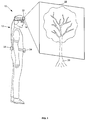
Fig. 1 is a block diagram of vision enhancement apparatus. -
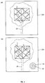
Fig. 2 is a pair of images showing:- (a) The user's natural view of a scene.
- (b) The user's view with a depth of field information included.
-
Fig. 3 is flowchart of the process for delivering the depth of field information into the users view. -
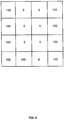
Fig. 4 is an image of an alternative type of image presented to the user. - Referring first to
Fig. 1 , thevision enhancement apparatus 10 supports a vision-impaired user 12 ofinterface equipment 14, such as vision spectacles that provide a stereoscopic image to the user's eyes. Theapparatus 10 comprises avideo camera 20 is mounted on the user's head that operates to acquire videodata representing scenes 22 in the vicinity of theuser 12. - An
object detection system 24 is also mounted on the user's waistband acquires object data about objects, such astree 26 in the vicinity of the user [step 300 inFig. 3 ]. In particular theobject detection system 24 determines how far thetree 26 is from the user 12 [step 302 inFig. 3 ]. This is achieved by simple reflection of ultrasonic transmissions emanating from thesystem 24 from thetree 26, and calculating the transit time. - Part of
tree 26 is also in thescene 22 filmed by the video camera 20 [step 304 inFig. 3 ]. - The
sight processor 28 is also mounted on the user's waistband to receive video data fromcamera 20 and object data fromobject detection system 24. The sight processor uses the distance information between the user and the tree to automatically insert real-time depth of field information about the detected tree into the video data [step 306 inFig. 3 ]. This information will then be visually presented to the user by means of the vision spectacles 14 [step 308 inFig. 3 ]. Thecamera 20,vision spectacles 14,object detection system 24 andimage processor 28 are all interconnected by wires, as shown; or wirelessly by a personal area network (PAN). - In this case the
user 12 has macular degeneration so their vision is obscured in the central region; as shown inFig. 2(a) where almost all the foliage of the tree is obscured whenuser 12 looks directly at it from this distance. - The image presented to the user is enhanced by the
sight processor 28. In this case thetree 26 is detected by theobject detection system 24, and thetree 26 is the only object detected. As a result, theobject detection system 24 sends data to the sight processor indicating the distance of the user from the tree. - In this case both the
user 12 andtree 26 are stationary, so thesight processor 28 includes a target 30 in the bottom right of the image displayed to the user. In the centre of target 30 is the encircled number '5' 32; as shown inFig. 2(b) . This indicates to theuser 12, in part of the image they can see and read, that the tree is directly in front of them and 5 metres away. - The direction of the
tree 26 is indicated by the position of thenumber 32 in the target 30; that is central = directly ahead. And, the distance is given by the number '5'. - In the event the
user 12 was walking forward, directly towards thetree 26, then thenumber 32 would be continually flashing - indicating change - and thenumber 32 would count down as the distance decreased. - It should be appreciated that the direction and distance information, in this case, is completely independent of the image of the
tree 26 being shown to theuser 12, since theuser 12 could be pointing thecamera 20 in another direction entirely and the image being shown in the vision spectacles could be of something else. However, the direction and distance information would remain unchanged, since theobject detection system 24 is mounted on the user's waistband. - In an alternative arrangement, the depth of field sensor is in the form of a non-visual depth sensing array, such as a large array of high resolution millimetre wave radar, or a 3D laser scanner, which generates a field of data representing distance measures that can be mapped into a grid by the
sight processor 28. - In this case, data acquired by the depth of field sensor can be used directly to stimulate the user's retina, without having to acquire any video data. For example, for a retinal implant or a bionic eye having between 100 and 1000 actual visual fields (roughly pixel equivalent), the
sight processor 28 can render the depth of field data directly as intensity on a 100 electrode array of the retinal implant or bionic eye. A pair of field sensors may also be used to provide a pair of stereoscopic signals, for respective eyes. - One exemplary mode involves the
sight processor 28 computing dense stereo depth across a field at high resolution, then taking a minimum depth value over each cell in the field, and applying that minimum value as a maximum to the cells of theinterface equipment 14. In practice, the absolute maximum value of each cell may be too error prone, and therefore the minimum is smoothed over a small region to increase robustness. Such a grid can then be presented to the user via theinterface equipment 14, so that theuser 12 sees an image as shown inFig. 4 . In this case, cells having value '5' represent an object that is 5 metres away while '100' represents no obstacles within 100 metres from theuser 12. - Although the invention has been described with reference to a simple example, it will readily be appreciated that far more sophisticated examples could be constructed. For instance object detection could be performed in many different ways, including by analysis of the video data. The presentation of the depth of field information could also be achieved in many different ways; for instance using a light, brightness or colour, moving graphics or other techniques.
- Also, the ground plane could be represented in the depth data by fitting a horizontal plane, and this can then be used to map distances parallel to the ground between the observer and an object. A phosphene could then be used to represent just the horizontal component of the distance from the observer to an object. This may be particularly useful if the resolution is very low, such as less than one hundred elements. Here each visual element could be used as a polar histogram of object distances. With more visual elements, each one could simply map the horizontal distance to the nearest object over its field of view, and then the elements are providing cylindrical coordinates. A gravity sensor or inertial navigation system could be used to assist plane fitting by estimating the direction of the ground plane.
Claims (15)
- Vision enhancement apparatus for a vision-impaired user of interface equipment, comprising:a passive sensor to acquire real-time high resolution data representing the vicinity of the user;a sight processor adapted to receive the acquired high resolution data, characterised in that said processor is further adapted to automatically:analyse the high resolution data to extract depth of field information concerning objects of interest'extract lower resolution data representing the vicinity of the user, and, provide both the depth of field information concerning objects of interest and the lower resolution data representing the vicinity of the user to the interface equipment to stimulate artificial vision for the user.
- Vision enhancement apparatus according to claim 1, wherein the passive sensor is a video image camera that captures a series of video images, and the depth of field information concerning objects of interest is derived from the captured video images.
- Vision enhancement apparatus according to claim 2, wherein the resulting depth of field information is inserted into the video data.
- Vision enhancement apparatus according to claim 1 or 2, wherein the low resolution data representing the vicinity of the user is obtained from the high resolution data by down sampling.
- Vision enhancement apparatus according to claim 3, wherein the user sees the depth of field information presented visually as a depth map.
- Vision enhancement apparatus according to claim 5 wherein the depth of field map is a cylindrical, radial or spherical grid over their field of vision.
- Vision enhancement apparatus according to claim 5 or 6, wherein the depth map colours or highlights objects of interest.
- Vision enhancement apparatus according to any one of the preceding claims, wherein depth of field information is conveyed as an indication of'time to contact'.
- Vision enhancement apparatus according to any one of the preceding claims, wherein a pair of video cameras are used to provide a pair of stereoscopic signals, for respective eyes, and these images are analysed in real time, using triangulation techniques, to extract depth of field information in the form of distance information from the user to objects of interest.
- Vision enhancement apparatus according to any one of the preceding claims, wherein the user has some remaining retinal function and the interface equipment comprises a 'visual display array' that operates to stimulate the remaining retinal function.
- Vision enhancement apparatus according to claim 10, wherein the user has an area of retina remaining with high image resolution, and the visual display array is used to stimulate that area.
- Vision enhancement apparatus according to claim 10 or 11, wherein where part of the retina does not function, the images are reordered so that the information about detected objects is directed to a functioning part of the retina.
- Vision enhancement apparatus according to any one of the preceding claims, wherein users with little or no retinal function have artificial vision stimulated by a cortical or pre-cortical implant.
- Vision enhancement apparatus according to claim 13, wherein the depth of field information concerning objects of interest is presented to the user by stimulating the production of phosphenes in the cortex that convey information.
- A method for providing informational signals by interface equipment, comprising the steps of:acquiring from a passive sensor real-time high resolution video data representing the vicinity of a user;analysing by a sight processor the high resolution data to extract depth of field information concerning objects of interest,extracting by the sight processor lower resolution data representing the vicinity of the user, andrendering by the sight processor both the depth of field information concerning objects of interest and the lower resolution data representing the vicinity of the user on the interface equipment.
Applications Claiming Priority (2)
| Application Number | Priority Date | Filing Date | Title |
|---|---|---|---|
| AU2009904959A AU2009904959A0 (en) | 2009-10-09 | Vision Enhancement for a Vision Impaired User | |
| PCT/AU2010/001320 WO2011041842A1 (en) | 2009-10-09 | 2010-10-07 | Vision enhancement for a vision impaired user |
Publications (3)
| Publication Number | Publication Date |
|---|---|
| EP2485692A1 EP2485692A1 (en) | 2012-08-15 |
| EP2485692A4 EP2485692A4 (en) | 2013-06-12 |
| EP2485692B1 true EP2485692B1 (en) | 2016-01-27 |
Family
ID=43856302
Family Applications (1)
| Application Number | Title | Priority Date | Filing Date |
|---|---|---|---|
| EP10821484.2A Active EP2485692B1 (en) | 2009-10-09 | 2010-10-07 | Vision enhancement for a vision impaired user |
Country Status (4)
| Country | Link |
|---|---|
| US (1) | US9162061B2 (en) |
| EP (1) | EP2485692B1 (en) |
| AU (1) | AU2010305323B2 (en) |
| WO (1) | WO2011041842A1 (en) |
Families Citing this family (23)
| Publication number | Priority date | Publication date | Assignee | Title |
|---|---|---|---|---|
| AU2012304260B2 (en) * | 2011-08-30 | 2017-06-08 | Monash University | System and method for processing sensor data for the visually impaired |
| EP2845184A1 (en) * | 2012-04-23 | 2015-03-11 | Yissum Research Development Company of the Hebrew University of Jerusalem Ltd. | Device for rehabilitating brain mechanism of visual perception using complementary sensual stimulations |
| WO2014125789A1 (en) * | 2013-02-14 | 2014-08-21 | Seiko Epson Corporation | Head mounted display and control method for head mounted display |
| WO2015010164A1 (en) * | 2013-07-22 | 2015-01-29 | National Ict Australia Limited | Enhancing vision for a vision impaired user |
| WO2015143203A1 (en) * | 2014-03-19 | 2015-09-24 | Schepens Eye Research Institute | Active confocal imaging systems and methods for visual prostheses |
| US12462415B2 (en) | 2014-05-06 | 2025-11-04 | Okkola Technologies, Llc | Stationary aerial platform scanning system utilizing measured distances for the construction, displaying terrain features and location of objects |
| US9851434B2 (en) * | 2014-05-06 | 2017-12-26 | Louis Caporizzo | Method and navigation system for assisting a visually impaired user to safely walk around obstructions and impediments |
| US11022681B2 (en) | 2014-05-06 | 2021-06-01 | Okkola Technologies, Llc | System and method for measuring and rendering terrain on a display |
| US10089900B2 (en) | 2014-05-30 | 2018-10-02 | Wolfcub Vision, Inc. | Systems and methods for expanding human perception |
| US10291845B2 (en) * | 2015-08-17 | 2019-05-14 | Nokia Technologies Oy | Method, apparatus, and computer program product for personalized depth of field omnidirectional video |
| WO2017043101A1 (en) * | 2015-09-08 | 2017-03-16 | ソニー株式会社 | Information processing device, information processing method, and program |
| US10049535B1 (en) * | 2016-04-14 | 2018-08-14 | Wolfcub Vision, Inc. | UV Gap-spotter |
| CN106074095B (en) * | 2016-05-26 | 2018-07-20 | 英华达(上海)科技有限公司 | A kind of low visual acuity person ancillary equipment and method |
| US10330935B2 (en) * | 2016-09-22 | 2019-06-25 | Apple Inc. | Predictive, foveated virtual reality system |
| US11160688B2 (en) * | 2016-11-10 | 2021-11-02 | Samsung Electronics Co., Ltd. | Visual aid display device and method of operating the same |
| US11298266B2 (en) | 2016-12-07 | 2022-04-12 | Second Sight Medical Products, Inc. | Depth filter for visual prostheses |
| WO2018183000A1 (en) | 2017-03-30 | 2018-10-04 | Schepens Eye Research Institute | Motion parallax in object recognition |
| US11338139B2 (en) | 2018-10-01 | 2022-05-24 | Biovisics Medical, Inc. | System and methods for controlled electrical modulation for vision therapy |
| US11305118B2 (en) | 2018-11-30 | 2022-04-19 | Biovisics Medical, Inc. | Head worn apparatuses for vision therapy |
| EP3952979A1 (en) | 2019-04-10 | 2022-02-16 | Biovisics Medical, Inc. | Systems and interfaces for ocular therapy |
| US11511112B2 (en) | 2019-06-14 | 2022-11-29 | Biovisics Medical, Inc. | Wearable medical device |
| WO2021011255A1 (en) | 2019-07-12 | 2021-01-21 | Biovisics Medical, Inc. | Ocular therapy modes and systems |
| US12589243B2 (en) | 2022-10-21 | 2026-03-31 | I-Lumen Scientific, Inc. | Ocular devices and controller interfaces for ocular therapy |
Family Cites Families (15)
| Publication number | Priority date | Publication date | Assignee | Title |
|---|---|---|---|---|
| US3654477A (en) | 1970-06-02 | 1972-04-04 | Bionic Instr Inc | Obstacle detection system for use by blind comprising plural ranging channels mounted on spectacle frames |
| US5728156A (en) * | 1996-08-06 | 1998-03-17 | Prism Opthalmics, L.L.C. | Prismatic intraocular lenses and related methods of in situ alteration of their optical characteristics |
| DE19820176A1 (en) | 1997-04-30 | 1998-11-12 | Ludger Prof Woeste | Orientation aid for blind and partially sighted persons |
| US6658299B1 (en) * | 2000-01-04 | 2003-12-02 | William H. Dobelle | Artificial system for vision and the like |
| US6927769B2 (en) * | 2000-11-21 | 2005-08-09 | Vrex, Inc. | Stereoscopic image processing on a computer system |
| US20020138264A1 (en) | 2001-03-21 | 2002-09-26 | International Business Machines Corporation | Apparatus to convey depth information in graphical images and method therefor |
| US6961458B2 (en) | 2001-04-27 | 2005-11-01 | International Business Machines Corporation | Method and apparatus for presenting 3-dimensional objects to visually impaired users |
| GB2376397A (en) * | 2001-06-04 | 2002-12-11 | Hewlett Packard Co | Virtual or augmented reality |
| US7308314B2 (en) * | 2002-06-06 | 2007-12-11 | Advanced Medical Electronics | Method and apparatus for sensory substitution, vision prosthesis, or low-vision enhancement utilizing thermal sensing |
| US7598976B2 (en) * | 2002-06-13 | 2009-10-06 | I See Tech Ltd. | Method and apparatus for a multisensor imaging and scene interpretation system to aid the visually impaired |
| US7311723B2 (en) * | 2003-07-11 | 2007-12-25 | University Of Washington | Scanning laser device and methods of use |
| US8078284B2 (en) * | 2004-05-25 | 2011-12-13 | Second Sight Medical Products, Inc. | Retinal prosthesis with a new configuration |
| US20070016425A1 (en) * | 2005-07-12 | 2007-01-18 | Koren Ward | Device for providing perception of the physical environment |
| DE102006060045A1 (en) * | 2006-12-19 | 2008-06-26 | Imi Intelligent Medical Implants Ag | Visual aid with three-dimensional image capture |
| US20080309913A1 (en) * | 2007-06-14 | 2008-12-18 | James John Fallon | Systems and methods for laser radar imaging for the blind and visually impaired |
-
2010
- 2010-10-07 AU AU2010305323A patent/AU2010305323B2/en not_active Ceased
- 2010-10-07 EP EP10821484.2A patent/EP2485692B1/en active Active
- 2010-10-07 WO PCT/AU2010/001320 patent/WO2011041842A1/en not_active Ceased
- 2010-10-07 US US13/500,606 patent/US9162061B2/en active Active
Also Published As
| Publication number | Publication date |
|---|---|
| AU2010305323A1 (en) | 2012-04-26 |
| US20120242801A1 (en) | 2012-09-27 |
| AU2010305323B2 (en) | 2015-02-12 |
| EP2485692A4 (en) | 2013-06-12 |
| US9162061B2 (en) | 2015-10-20 |
| EP2485692A1 (en) | 2012-08-15 |
| WO2011041842A1 (en) | 2011-04-14 |
Similar Documents
| Publication | Publication Date | Title |
|---|---|---|
| AU2010305323B2 (en) | Vision enhancement for a vision impaired user | |
| US11006100B1 (en) | Smart glasses system | |
| US10062303B2 (en) | Object tracking for artificial vision | |
| EP3195192A1 (en) | Method and system for detecting obstacles for a visual prosthesis | |
| US9495008B2 (en) | Detecting a primary user of a device | |
| JP6527507B2 (en) | Smart Prostheses to Promote Artificial Vision Using Scene Abstraction | |
| McCarthy et al. | Mobility and low contrast trip hazard avoidance using augmented depth | |
| US20150279022A1 (en) | Visualization of Spatial and Other Relationships | |
| Meers et al. | A substitute vision system for providing 3D perception and GPS navigation via electro-tactile stimulation | |
| US11442534B1 (en) | Smart glasses system | |
| CN108038453A (en) | A kind of driver's state-detection and identifying system based on RGBD | |
| JP6739681B2 (en) | Driving support device, driving support method, and driving support program | |
| WO2012142202A1 (en) | Apparatus, systems and methods for providing motion tracking using a personal viewing device | |
| EP3163407A1 (en) | Method and apparatus for alerting to head mounted display user | |
| EP4354401A1 (en) | Method and system of detecting obstacle elements with a visual aid device | |
| CN110706268B (en) | Distance adjusting method and electronic equipment | |
| KR101187773B1 (en) | advertisement system using motion cognition. | |
| CN108140362A (en) | Display method, display device, electronic equipment and computer program product | |
| CN107749060A (en) | Machine vision equipment and based on flying time technology three-dimensional information gathering algorithm | |
| KR20240141315A (en) | An orientation assistance system comprising means for obtaining a real or virtual visual environment, non-visual human-machine interface means, and means for processing a digital representation of said visual environment. | |
| WO2015198284A1 (en) | Reality description system and method | |
| US10984234B2 (en) | Method and apparatus for image recognition based on retina prosthesis | |
| Milotta et al. | An electronic travel aid to assist blind and visually impaired people to avoid obstacles | |
| US10762715B2 (en) | Information processing apparatus | |
| JP2024035533A (en) | information processing equipment |
Legal Events
| Date | Code | Title | Description |
|---|---|---|---|
| PUAI | Public reference made under article 153(3) epc to a published international application that has entered the european phase |
Free format text: ORIGINAL CODE: 0009012 |
|
| 17P | Request for examination filed |
Effective date: 20120430 |
|
| AK | Designated contracting states |
Kind code of ref document: A1 Designated state(s): AL AT BE BG CH CY CZ DE DK EE ES FI FR GB GR HR HU IE IS IT LI LT LU LV MC MK MT NL NO PL PT RO RS SE SI SK SM TR |
|
| DAX | Request for extension of the european patent (deleted) | ||
| A4 | Supplementary search report drawn up and despatched |
Effective date: 20130510 |
|
| RIC1 | Information provided on ipc code assigned before grant |
Ipc: A61F 9/08 20060101AFI20130503BHEP Ipc: G06F 19/00 20110101ALI20130503BHEP Ipc: G01S 13/88 20060101ALI20130503BHEP |
|
| GRAP | Despatch of communication of intention to grant a patent |
Free format text: ORIGINAL CODE: EPIDOSNIGR1 |
|
| INTG | Intention to grant announced |
Effective date: 20140923 |
|
| 17Q | First examination report despatched |
Effective date: 20150427 |
|
| GRAP | Despatch of communication of intention to grant a patent |
Free format text: ORIGINAL CODE: EPIDOSNIGR1 |
|
| INTG | Intention to grant announced |
Effective date: 20150729 |
|
| GRAS | Grant fee paid |
Free format text: ORIGINAL CODE: EPIDOSNIGR3 |
|
| GRAA | (expected) grant |
Free format text: ORIGINAL CODE: 0009210 |
|
| AK | Designated contracting states |
Kind code of ref document: B1 Designated state(s): AL AT BE BG CH CY CZ DE DK EE ES FI FR GB GR HR HU IE IS IT LI LT LU LV MC MK MT NL NO PL PT RO RS SE SI SK SM TR |
|
| REG | Reference to a national code |
Ref country code: GB Ref legal event code: FG4D |
|
| REG | Reference to a national code |
Ref country code: CH Ref legal event code: EP |
|
| REG | Reference to a national code |
Ref country code: AT Ref legal event code: REF Ref document number: 772327 Country of ref document: AT Kind code of ref document: T Effective date: 20160215 |
|
| REG | Reference to a national code |
Ref country code: IE Ref legal event code: FG4D |
|
| REG | Reference to a national code |
Ref country code: DE Ref legal event code: R096 Ref document number: 602010030441 Country of ref document: DE |
|
| REG | Reference to a national code |
Ref country code: CH Ref legal event code: NV Representative=s name: SCHMAUDER AND PARTNER AG PATENT- UND MARKENANW, CH |
|
| REG | Reference to a national code |
Ref country code: LT Ref legal event code: MG4D |
|
| REG | Reference to a national code |
Ref country code: NL Ref legal event code: MP Effective date: 20160127 |
|
| REG | Reference to a national code |
Ref country code: AT Ref legal event code: MK05 Ref document number: 772327 Country of ref document: AT Kind code of ref document: T Effective date: 20160127 |
|
| PG25 | Lapsed in a contracting state [announced via postgrant information from national office to epo] |
Ref country code: NL Free format text: LAPSE BECAUSE OF FAILURE TO SUBMIT A TRANSLATION OF THE DESCRIPTION OR TO PAY THE FEE WITHIN THE PRESCRIBED TIME-LIMIT Effective date: 20160127 |
|
| PG25 | Lapsed in a contracting state [announced via postgrant information from national office to epo] |
Ref country code: FI Free format text: LAPSE BECAUSE OF FAILURE TO SUBMIT A TRANSLATION OF THE DESCRIPTION OR TO PAY THE FEE WITHIN THE PRESCRIBED TIME-LIMIT Effective date: 20160127 Ref country code: IT Free format text: LAPSE BECAUSE OF FAILURE TO SUBMIT A TRANSLATION OF THE DESCRIPTION OR TO PAY THE FEE WITHIN THE PRESCRIBED TIME-LIMIT Effective date: 20160127 Ref country code: ES Free format text: LAPSE BECAUSE OF FAILURE TO SUBMIT A TRANSLATION OF THE DESCRIPTION OR TO PAY THE FEE WITHIN THE PRESCRIBED TIME-LIMIT Effective date: 20160127 Ref country code: NO Free format text: LAPSE BECAUSE OF FAILURE TO SUBMIT A TRANSLATION OF THE DESCRIPTION OR TO PAY THE FEE WITHIN THE PRESCRIBED TIME-LIMIT Effective date: 20160427 Ref country code: GR Free format text: LAPSE BECAUSE OF FAILURE TO SUBMIT A TRANSLATION OF THE DESCRIPTION OR TO PAY THE FEE WITHIN THE PRESCRIBED TIME-LIMIT Effective date: 20160428 Ref country code: HR Free format text: LAPSE BECAUSE OF FAILURE TO SUBMIT A TRANSLATION OF THE DESCRIPTION OR TO PAY THE FEE WITHIN THE PRESCRIBED TIME-LIMIT Effective date: 20160127 |
|
| PG25 | Lapsed in a contracting state [announced via postgrant information from national office to epo] |
Ref country code: PL Free format text: LAPSE BECAUSE OF FAILURE TO SUBMIT A TRANSLATION OF THE DESCRIPTION OR TO PAY THE FEE WITHIN THE PRESCRIBED TIME-LIMIT Effective date: 20160127 Ref country code: LT Free format text: LAPSE BECAUSE OF FAILURE TO SUBMIT A TRANSLATION OF THE DESCRIPTION OR TO PAY THE FEE WITHIN THE PRESCRIBED TIME-LIMIT Effective date: 20160127 Ref country code: AT Free format text: LAPSE BECAUSE OF FAILURE TO SUBMIT A TRANSLATION OF THE DESCRIPTION OR TO PAY THE FEE WITHIN THE PRESCRIBED TIME-LIMIT Effective date: 20160127 Ref country code: LV Free format text: LAPSE BECAUSE OF FAILURE TO SUBMIT A TRANSLATION OF THE DESCRIPTION OR TO PAY THE FEE WITHIN THE PRESCRIBED TIME-LIMIT Effective date: 20160127 Ref country code: RS Free format text: LAPSE BECAUSE OF FAILURE TO SUBMIT A TRANSLATION OF THE DESCRIPTION OR TO PAY THE FEE WITHIN THE PRESCRIBED TIME-LIMIT Effective date: 20160127 Ref country code: IS Free format text: LAPSE BECAUSE OF FAILURE TO SUBMIT A TRANSLATION OF THE DESCRIPTION OR TO PAY THE FEE WITHIN THE PRESCRIBED TIME-LIMIT Effective date: 20160527 Ref country code: PT Free format text: LAPSE BECAUSE OF FAILURE TO SUBMIT A TRANSLATION OF THE DESCRIPTION OR TO PAY THE FEE WITHIN THE PRESCRIBED TIME-LIMIT Effective date: 20160527 Ref country code: SE Free format text: LAPSE BECAUSE OF FAILURE TO SUBMIT A TRANSLATION OF THE DESCRIPTION OR TO PAY THE FEE WITHIN THE PRESCRIBED TIME-LIMIT Effective date: 20160127 |
|
| REG | Reference to a national code |
Ref country code: DE Ref legal event code: R097 Ref document number: 602010030441 Country of ref document: DE |
|
| PG25 | Lapsed in a contracting state [announced via postgrant information from national office to epo] |
Ref country code: DK Free format text: LAPSE BECAUSE OF FAILURE TO SUBMIT A TRANSLATION OF THE DESCRIPTION OR TO PAY THE FEE WITHIN THE PRESCRIBED TIME-LIMIT Effective date: 20160127 Ref country code: EE Free format text: LAPSE BECAUSE OF FAILURE TO SUBMIT A TRANSLATION OF THE DESCRIPTION OR TO PAY THE FEE WITHIN THE PRESCRIBED TIME-LIMIT Effective date: 20160127 |
|
| REG | Reference to a national code |
Ref country code: FR Ref legal event code: PLFP Year of fee payment: 7 |
|
| PG25 | Lapsed in a contracting state [announced via postgrant information from national office to epo] |
Ref country code: CZ Free format text: LAPSE BECAUSE OF FAILURE TO SUBMIT A TRANSLATION OF THE DESCRIPTION OR TO PAY THE FEE WITHIN THE PRESCRIBED TIME-LIMIT Effective date: 20160127 Ref country code: RO Free format text: LAPSE BECAUSE OF FAILURE TO SUBMIT A TRANSLATION OF THE DESCRIPTION OR TO PAY THE FEE WITHIN THE PRESCRIBED TIME-LIMIT Effective date: 20160127 Ref country code: SM Free format text: LAPSE BECAUSE OF FAILURE TO SUBMIT A TRANSLATION OF THE DESCRIPTION OR TO PAY THE FEE WITHIN THE PRESCRIBED TIME-LIMIT Effective date: 20160127 Ref country code: SK Free format text: LAPSE BECAUSE OF FAILURE TO SUBMIT A TRANSLATION OF THE DESCRIPTION OR TO PAY THE FEE WITHIN THE PRESCRIBED TIME-LIMIT Effective date: 20160127 |
|
| PLBE | No opposition filed within time limit |
Free format text: ORIGINAL CODE: 0009261 |
|
| STAA | Information on the status of an ep patent application or granted ep patent |
Free format text: STATUS: NO OPPOSITION FILED WITHIN TIME LIMIT |
|
| PG25 | Lapsed in a contracting state [announced via postgrant information from national office to epo] |
Ref country code: BE Free format text: LAPSE BECAUSE OF FAILURE TO SUBMIT A TRANSLATION OF THE DESCRIPTION OR TO PAY THE FEE WITHIN THE PRESCRIBED TIME-LIMIT Effective date: 20160127 |
|
| 26N | No opposition filed |
Effective date: 20161028 |
|
| PG25 | Lapsed in a contracting state [announced via postgrant information from national office to epo] |
Ref country code: BG Free format text: LAPSE BECAUSE OF FAILURE TO SUBMIT A TRANSLATION OF THE DESCRIPTION OR TO PAY THE FEE WITHIN THE PRESCRIBED TIME-LIMIT Effective date: 20160427 Ref country code: SI Free format text: LAPSE BECAUSE OF FAILURE TO SUBMIT A TRANSLATION OF THE DESCRIPTION OR TO PAY THE FEE WITHIN THE PRESCRIBED TIME-LIMIT Effective date: 20160127 |
|
| REG | Reference to a national code |
Ref country code: IE Ref legal event code: MM4A |
|
| PG25 | Lapsed in a contracting state [announced via postgrant information from national office to epo] |
Ref country code: LU Free format text: LAPSE BECAUSE OF NON-PAYMENT OF DUE FEES Effective date: 20161007 |
|
| REG | Reference to a national code |
Ref country code: FR Ref legal event code: PLFP Year of fee payment: 8 |
|
| PG25 | Lapsed in a contracting state [announced via postgrant information from national office to epo] |
Ref country code: IE Free format text: LAPSE BECAUSE OF NON-PAYMENT OF DUE FEES Effective date: 20161007 |
|
| PG25 | Lapsed in a contracting state [announced via postgrant information from national office to epo] |
Ref country code: CY Free format text: LAPSE BECAUSE OF FAILURE TO SUBMIT A TRANSLATION OF THE DESCRIPTION OR TO PAY THE FEE WITHIN THE PRESCRIBED TIME-LIMIT Effective date: 20160127 Ref country code: HU Free format text: LAPSE BECAUSE OF FAILURE TO SUBMIT A TRANSLATION OF THE DESCRIPTION OR TO PAY THE FEE WITHIN THE PRESCRIBED TIME-LIMIT; INVALID AB INITIO Effective date: 20101007 |
|
| PG25 | Lapsed in a contracting state [announced via postgrant information from national office to epo] |
Ref country code: MK Free format text: LAPSE BECAUSE OF FAILURE TO SUBMIT A TRANSLATION OF THE DESCRIPTION OR TO PAY THE FEE WITHIN THE PRESCRIBED TIME-LIMIT Effective date: 20160127 Ref country code: MT Free format text: LAPSE BECAUSE OF NON-PAYMENT OF DUE FEES Effective date: 20161031 Ref country code: MC Free format text: LAPSE BECAUSE OF FAILURE TO SUBMIT A TRANSLATION OF THE DESCRIPTION OR TO PAY THE FEE WITHIN THE PRESCRIBED TIME-LIMIT Effective date: 20160127 Ref country code: TR Free format text: LAPSE BECAUSE OF FAILURE TO SUBMIT A TRANSLATION OF THE DESCRIPTION OR TO PAY THE FEE WITHIN THE PRESCRIBED TIME-LIMIT Effective date: 20160127 |
|
| REG | Reference to a national code |
Ref country code: FR Ref legal event code: PLFP Year of fee payment: 9 |
|
| PG25 | Lapsed in a contracting state [announced via postgrant information from national office to epo] |
Ref country code: AL Free format text: LAPSE BECAUSE OF FAILURE TO SUBMIT A TRANSLATION OF THE DESCRIPTION OR TO PAY THE FEE WITHIN THE PRESCRIBED TIME-LIMIT Effective date: 20160127 |
|
| P01 | Opt-out of the competence of the unified patent court (upc) registered |
Effective date: 20230524 |
|
| PGFP | Annual fee paid to national office [announced via postgrant information from national office to epo] |
Ref country code: DE Payment date: 20241022 Year of fee payment: 15 |
|
| PGFP | Annual fee paid to national office [announced via postgrant information from national office to epo] |
Ref country code: GB Payment date: 20241011 Year of fee payment: 15 |
|
| PGFP | Annual fee paid to national office [announced via postgrant information from national office to epo] |
Ref country code: FR Payment date: 20241024 Year of fee payment: 15 |
|
| PGFP | Annual fee paid to national office [announced via postgrant information from national office to epo] |
Ref country code: CH Payment date: 20241101 Year of fee payment: 15 |