EP2485372A2 - Conductive component and method for treating the conductive component - Google Patents
Conductive component and method for treating the conductive component Download PDFInfo
- Publication number
- EP2485372A2 EP2485372A2 EP12153528A EP12153528A EP2485372A2 EP 2485372 A2 EP2485372 A2 EP 2485372A2 EP 12153528 A EP12153528 A EP 12153528A EP 12153528 A EP12153528 A EP 12153528A EP 2485372 A2 EP2485372 A2 EP 2485372A2
- Authority
- EP
- European Patent Office
- Prior art keywords
- component
- layer
- approximately
- exterior layer
- exterior
- Prior art date
- Legal status (The legal status is an assumption and is not a legal conclusion. Google has not performed a legal analysis and makes no representation as to the accuracy of the status listed.)
- Withdrawn
Links
- 238000000034 method Methods 0.000 title claims abstract description 39
- 238000000137 annealing Methods 0.000 claims abstract description 35
- 238000001816 cooling Methods 0.000 claims abstract description 23
- 238000010438 heat treatment Methods 0.000 claims abstract description 19
- RYGMFSIKBFXOCR-UHFFFAOYSA-N Copper Chemical compound [Cu] RYGMFSIKBFXOCR-UHFFFAOYSA-N 0.000 claims description 13
- 229910052802 copper Inorganic materials 0.000 claims description 13
- 239000010949 copper Substances 0.000 claims description 13
- 230000006698 induction Effects 0.000 claims description 3
- 238000010791 quenching Methods 0.000 claims description 2
- 230000000171 quenching effect Effects 0.000 claims description 2
- 230000005611 electricity Effects 0.000 description 17
- 239000000463 material Substances 0.000 description 14
- 239000004020 conductor Substances 0.000 description 11
- 235000019589 hardness Nutrition 0.000 description 7
- 239000007789 gas Substances 0.000 description 6
- 239000007787 solid Substances 0.000 description 3
- 238000012986 modification Methods 0.000 description 2
- 230000004048 modification Effects 0.000 description 2
- 229910001316 Ag alloy Inorganic materials 0.000 description 1
- 229910000838 Al alloy Inorganic materials 0.000 description 1
- 229910000881 Cu alloy Inorganic materials 0.000 description 1
- BQCADISMDOOEFD-UHFFFAOYSA-N Silver Chemical compound [Ag] BQCADISMDOOEFD-UHFFFAOYSA-N 0.000 description 1
- 229910052782 aluminium Inorganic materials 0.000 description 1
- XAGFODPZIPBFFR-UHFFFAOYSA-N aluminium Chemical compound [Al] XAGFODPZIPBFFR-UHFFFAOYSA-N 0.000 description 1
- QVGXLLKOCUKJST-UHFFFAOYSA-N atomic oxygen Chemical compound [O] QVGXLLKOCUKJST-UHFFFAOYSA-N 0.000 description 1
- 230000001627 detrimental effect Effects 0.000 description 1
- 238000010586 diagram Methods 0.000 description 1
- 229910052751 metal Inorganic materials 0.000 description 1
- 239000002184 metal Substances 0.000 description 1
- 229910001092 metal group alloy Inorganic materials 0.000 description 1
- 239000001301 oxygen Substances 0.000 description 1
- 229910052760 oxygen Inorganic materials 0.000 description 1
- 238000010248 power generation Methods 0.000 description 1
- 238000001953 recrystallisation Methods 0.000 description 1
- 239000012779 reinforcing material Substances 0.000 description 1
- 229910052709 silver Inorganic materials 0.000 description 1
- 239000004332 silver Substances 0.000 description 1
Images


Classifications
-
- H—ELECTRICITY
- H02—GENERATION; CONVERSION OR DISTRIBUTION OF ELECTRIC POWER
- H02K—DYNAMO-ELECTRIC MACHINES
- H02K3/00—Details of windings
- H02K3/02—Windings characterised by the conductor material
-
- C—CHEMISTRY; METALLURGY
- C21—METALLURGY OF IRON
- C21D—MODIFYING THE PHYSICAL STRUCTURE OF FERROUS METALS; GENERAL DEVICES FOR HEAT TREATMENT OF FERROUS OR NON-FERROUS METALS OR ALLOYS; MAKING METAL MALLEABLE, e.g. BY DECARBURISATION OR TEMPERING
- C21D1/00—General methods or devices for heat treatment, e.g. annealing, hardening, quenching or tempering
- C21D1/26—Methods of annealing
-
- C—CHEMISTRY; METALLURGY
- C21—METALLURGY OF IRON
- C21D—MODIFYING THE PHYSICAL STRUCTURE OF FERROUS METALS; GENERAL DEVICES FOR HEAT TREATMENT OF FERROUS OR NON-FERROUS METALS OR ALLOYS; MAKING METAL MALLEABLE, e.g. BY DECARBURISATION OR TEMPERING
- C21D1/00—General methods or devices for heat treatment, e.g. annealing, hardening, quenching or tempering
- C21D1/34—Methods of heating
- C21D1/42—Induction heating
-
- C—CHEMISTRY; METALLURGY
- C22—METALLURGY; FERROUS OR NON-FERROUS ALLOYS; TREATMENT OF ALLOYS OR NON-FERROUS METALS
- C22F—CHANGING THE PHYSICAL STRUCTURE OF NON-FERROUS METALS AND NON-FERROUS ALLOYS
- C22F1/00—Changing the physical structure of non-ferrous metals or alloys by heat treatment or by hot or cold working
-
- C—CHEMISTRY; METALLURGY
- C22—METALLURGY; FERROUS OR NON-FERROUS ALLOYS; TREATMENT OF ALLOYS OR NON-FERROUS METALS
- C22F—CHANGING THE PHYSICAL STRUCTURE OF NON-FERROUS METALS AND NON-FERROUS ALLOYS
- C22F1/00—Changing the physical structure of non-ferrous metals or alloys by heat treatment or by hot or cold working
- C22F1/08—Changing the physical structure of non-ferrous metals or alloys by heat treatment or by hot or cold working of copper or alloys based thereon
-
- H—ELECTRICITY
- H01—ELECTRIC ELEMENTS
- H01B—CABLES; CONDUCTORS; INSULATORS; SELECTION OF MATERIALS FOR THEIR CONDUCTIVE, INSULATING OR DIELECTRIC PROPERTIES
- H01B1/00—Conductors or conductive bodies characterised by the conductive materials; Selection of materials as conductors
- H01B1/02—Conductors or conductive bodies characterised by the conductive materials; Selection of materials as conductors mainly consisting of metals or alloys
- H01B1/026—Alloys based on copper
-
- H—ELECTRICITY
- H02—GENERATION; CONVERSION OR DISTRIBUTION OF ELECTRIC POWER
- H02K—DYNAMO-ELECTRIC MACHINES
- H02K15/00—Processes or apparatus specially adapted for manufacturing, assembling, maintaining or repairing of dynamo-electric machines
- H02K15/12—Impregnating, moulding insulation, heating or drying of windings, stators, rotors or machines
-
- C—CHEMISTRY; METALLURGY
- C21—METALLURGY OF IRON
- C21D—MODIFYING THE PHYSICAL STRUCTURE OF FERROUS METALS; GENERAL DEVICES FOR HEAT TREATMENT OF FERROUS OR NON-FERROUS METALS OR ALLOYS; MAKING METAL MALLEABLE, e.g. BY DECARBURISATION OR TEMPERING
- C21D2221/00—Treating localised areas of an article
- C21D2221/10—Differential treatment of inner with respect to outer regions, e.g. core and periphery, respectively
-
- H—ELECTRICITY
- H01—ELECTRIC ELEMENTS
- H01B—CABLES; CONDUCTORS; INSULATORS; SELECTION OF MATERIALS FOR THEIR CONDUCTIVE, INSULATING OR DIELECTRIC PROPERTIES
- H01B13/00—Apparatus or processes specially adapted for manufacturing conductors or cables
- H01B13/0016—Apparatus or processes specially adapted for manufacturing conductors or cables for heat treatment
-
- Y—GENERAL TAGGING OF NEW TECHNOLOGICAL DEVELOPMENTS; GENERAL TAGGING OF CROSS-SECTIONAL TECHNOLOGIES SPANNING OVER SEVERAL SECTIONS OF THE IPC; TECHNICAL SUBJECTS COVERED BY FORMER USPC CROSS-REFERENCE ART COLLECTIONS [XRACs] AND DIGESTS
- Y02—TECHNOLOGIES OR APPLICATIONS FOR MITIGATION OR ADAPTATION AGAINST CLIMATE CHANGE
- Y02P—CLIMATE CHANGE MITIGATION TECHNOLOGIES IN THE PRODUCTION OR PROCESSING OF GOODS
- Y02P10/00—Technologies related to metal processing
- Y02P10/25—Process efficiency
Definitions
- the present disclosure relates in general to conductive components. More specifically, the present disclosure relates to methods for treating conductive components to modify conduction through the components and conductive components with modified conduction characteristics.
- Turbine systems are widely utilized in fields such as power generation.
- a conventional gas turbine system includes a compressor, a combustor, and a turbine connected to a generator.
- the mechanical energy produced by the compressor, combustor and turbine is transferred to the generator.
- the generator then converts the mechanical energy to electrical energy that may be deployed to a utility grid.
- Various components of the generator, and specifically of the generator stator may be formed from electrically conductive materials. Frequently, for example, the components are formed from copper. Alternating current (“AC”) electricity is transmitted through these components in the stator.
- AC Alternating current
- These conductive materials when untreated, may be poor conductors.
- hard copper is a relatively strong material, but is a poor conductor when compared to, for example, soft copper.
- the conductive materials when the conductive materials are treated such that they are better conductors, the materials lose their strength. This may be detrimental to the operation of the generator.
- the components formed from these treated materials may need to support their own weight and endure fatigue loading.
- the use of additional materials or other reinforcing materials may be required to support the components, which are expensive, heavy, and inefficient.
- an improved conductive component and an improved method for treating the conductive component are desired in the art.
- a conductive component and a method for treating the conductive component that improve the conductive capacity of the component while preventing significant losses in the strength of the component would be advantageous.
- a method for treating a conductive component to modify conduction through the component includes heating the component such that annealing of an exterior layer of the component occurs without annealing of an interior layer of the component, wherein the interior layer is disposed adjacent to and integral with the exterior layer.
- the method further includes cooling the component such that annealing of the exterior layer ceases without annealing of the interior layer.
- a conductive component in another embodiment, includes an annealed exterior layer having a thickness of less than or equal to approximately 10 millimeters, and a non-annealed interior layer disposed adjacent to and integral with the exterior layer.
- FIG. 1 is a schematic illustration of a gas turbine system
- FIG. 2 is a perspective view of a stator of a generator according to one embodiment of the present disclosure
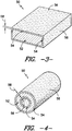
- FIG. 3 is a cross-sectional view of a conductive component after treating according to one embodiment of the present disclosure.
- FIG. 4 is a cross-section al view of a conductive component after treating according to another embodiment of the present disclosure.
- FIG. 1 is a schematic diagram of a gas turbine system 10.
- the system 10 may include a compressor 12, a combustor 14, and a turbine 16. Further, the system 10 may include a plurality of compressors 12, combustors 14, and turbines 16. The compressors 12 and turbines 16 may be coupled by a shaft 18.
- the shaft 18 may be a single shaft or a plurality of shaft segments coupled together to form shaft 18.
- Various other systems, such as steam turbine systems may be connected to the gas turbine system 10. Further, it should be understood that the present disclosure is not limited to gas turbine systems 10, and rather that any suitable gas, steam, or other turbine system is within the scope and spirit of the present disclosure.
- the system 10 may further include a generator 20.
- the generator 20 may accept mechanical energy developed by the other components of the system 10 and convert this energy into electrical energy.
- the generator 20 may include a rotor (not shown) and a stator 22.
- the rotor is a generally movable component of the generator 20, while the stator 22 is a generally stationary component of the generator 22.
- the stator 22 may include a variety of conductive components. These conductive components may conduct electricity, such as AC electricity, therethrough, and provide this electricity to, for example, a utility grid.
- an array of stator bars 32 may conduct electricity therethrough.
- Each stator bar 32 may be formed from a plurality of conductive strands, such as copper strands.
- Various of the stator bars 32 may be connected by series connectors 34 to form series connections therebetween. Additional connections may be formed through the connection of, for example, phase connectors 36.
- the phase connectors 36 may be connected to the stator bars 32 and/or series connectors 34 to provide additional connections, such as connections between various phases of AC electricity that may be produced by the generator 20.
- the generator 20 may produce three phases of AC electricity.
- the phase connectors 36 may be utilized to provide connections between these phases.
- connection rings 38 may be generally annular or arcuate components that are disposed at an end of the stator 22. Electricity may be flowed through the connection rings 38 out of the generator 20 and to a utility grid or other suitable location.
- the connections rings 38 may be connected by various bars or components (not shown) to high-voltage bushings (not shown). The high-voltage bushings may extract the electricity from the generator 20.
- generator 20 is merely various components of one embodiment of a generator, and that any suitable generator and arrangement of components therein is within the scope and spirit of the present disclosure.
- various components of the generator 20 are conductive components configured to conduct electricity, such as AC electricity, therethrough.
- the components utilized in generators were generally formed from either untreated materials that were relatively strong but relatively bad conductors, or treated materials that were relative good conductors but relatively weak.
- the present disclosure is further directed to an improved method for treating a conductive component 50, such as a conductive component utilized in a generator 20, to modify, such as improve, conduction through the component 50, and to an improved conductive component 50.
- these components are treated such that the resulting treated components are both relatively good conductors and relatively strong.
- the present disclosure discusses the benefits of the improved method and component in the context of a generator 20 and system 10, the present disclosure is not limited to the use of the component, or the method for treating the component, in a generator 20. Rather, any suitable component alone or utilized in any suitable device or process is within the scope and spirit of the present disclosure.
- FIGS. 3 and 4 illustrate various embodiments of the component 50 of the present disclosure.
- the component 50 may be formed from copper or a copper alloy.
- the component 50 may be formed from tough pitch copper, while in other embodiments, the component 50 may be formed from oxygen free copper.
- the component 50 may be formed from aluminum or an aluminum alloy, silver or a silver alloy, or any other suitable metal, metal alloy, or other suitable material.
- the component 50 may be a component of a generator 20, as discussed above.
- the component 50 may be a stator bar 32, a series connector 34, a phase connector 36, a connection ring 38, a high-voltage bushing, or any other suitable component of the generator 20.
- the component 50 of the present disclosure includes an interior layer 52 or a plurality of interior layers 52, and an exterior layer 54 or a plurality of exterior layers 54.
- the interior layer 52 may be adjacent to and integral with the exterior layer 54.
- Exterior layer 54 may defme an exterior surface 56 or exterior surfaces 56 of the component 50.
- the component 50 may be a solid bar.
- the component 50 may be a hollow tube.
- the component 50 may have a plurality of exterior layers 54.
- a plurality of exterior layers 54 generally encompass the entire exterior of the component 50 or various portions thereof.
- each of the outer surfaces may be an exterior surface 56 defined by an exterior layer 54.
- the inner surface and the outer surface, as well as the edge surfaces may be exterior surfaces 56 defined by exterior layers 54.
- component 50 is not limited to solid bars and hollow tubes as disclosed above. Rather, any suitably shaped component having any suitable size is within the scope of the present disclosure.
- interior layer 52 and exterior layer 54 may be integral portions of the component 50.
- the interior layer 52 and exterior layer 54 are merely portions of the material forming the component 50.
- interior layer 52 and exterior layer 54 may be indistinguishable.
- various or all of the interior layers 52 and exterior layers 54 may be distinguishable from each other, as discussed below. Treating of the component according to the present method may thus treat an exterior layer or layer 54 through annealing, while preventing annealing of the interior layer or layers 52. After treatment, the exterior layer or layer 54 may be annealed, while the associated interior layers 52 may remain not annealed.
- the method includes, for example, heating the component 50 such that annealing of an exterior layer 54 or plurality of exterior layers 54 occurs.
- annealing occurs when recrystallization of the material begins to occur. This is based on the material being annealed, the temperature at which the material is being heated, the time during which the material is being heated, along with other variables as is generally known in the annealing art.
- Annealing of exterior layers 54 may distinguish and form annealed exterior layers 54. For example, annealing may begin at the exterior surfaces 56 and extend inward, gradually annealing the exterior layers 54.
- this heating to cause annealing may occur without annealing of the interior layer 52.
- heating of the component 50 as discussed may be stopped before the interior layer 52 begins annealing.
- the interior layer 52 is defined by the annealing of exterior layer 54, such that the interior layer 52 begins where annealing has not occurred.
- the method further includes cooling the component 50, such as cooling the component 50 after heating of the component 50. Cooling according to the present disclosure may occur such that annealing of the exterior layer 54 ceases without annealing of the interior layer 52. Thus, according to the present disclosure, only exterior layer 54 is annealed, while interior layer 52 is not annealed.
- the present method may produce a conductive component 50 that is a relatively good conductor and is relatively strong.
- annealing of the exterior layer 54 may cause the exterior layer 54 to have better conductive properties, while not annealing the interior layer 52 may allow the interior layer 52 to maintain the strength properties of the material utilized for the conductive component 50.
- the conductive component 50 produced according to the present method may be particularly advantageous with regard to the conduction of AC electricity through the component 50.
- AC electricity generally flows primarily through the outer skin or outer layer of a conductive material.
- the density of the AC current, and thus the amount of AC electricity, is reduced exponentially with respect to distance from the surface of the material.
- the component 50 according to the present disclosure advantageously allows the majority of AC electricity flowing through the component 50, which is flowing through exterior layer or layers 54, to be better conducted through the component 50 due to annealing of the component.
- the strength of the component 50 is advantageously maintained in the portion of the component 50 through which only a minimal portion of the AC electricity is flowed by not annealing the interior layer or layers 52.
- heating of the component 50 may comprise induction heating of the component 50.
- the heating step may be performed at a frequency of greater than or equal to approximately 100 kHz. In other exemplary embodiments, the heating step may be performed at a frequency in the range between approximately 100 kHz and approximately 400 kHz. It should be understood, however, that the present disclosure is not limited to the above disclosed frequencies, and rather that any suitable frequency is within the scope and spirit of the present disclosure.
- the present disclosure is not limited to induction heating. Rather, any suitable heating method that will anneal the component 50 as required is within the scope of the present disclosure.
- the cooling step may comprise quenching. Additionally or alternatively, the cooling step may comprise air cooling, oven cooling, or any other suitable cooling technique. Further, it should be understood that the present disclosure is not limited to any of the above disclosed cooling techniques, and rather that any suitable technique for suitably cooling the component 50 after annealing is within the scope and spirit of the present disclosure.
- the heating step and the cooling step of the present disclosure may produce a full anneal of the exterior layer.
- the heating step and the cooling step may produce an intermediate anneal, or any other suitable anneal. It should be understood that the present disclosure is not limited to any of the above disclosed types of anneals, and rather that any suitable anneal type is within the scope and spirit of the present disclosure.
- the method and the conductive component 50 may allow AC electricity to better flow through exterior layer 54 while maintaining the strength of interior layer 52.
- the exterior layer 54 may have a thickness 58. In exemplary embodiments, this thickness 58 may desirably be minimized.
- the thickness 58 of the exterior layer 54 may, in some embodiments, be less than or equal to approximately 10 millimeters, or less than or equal to approximately 9 millimeters, or less than or equal to approximately 5 millimeters, or less than or equal to approximately 4 millimeters.
- the interior layers 52 and exterior layers 54 of conductive component 50 after cooling according to the present method, may further have varying hardnesses.
- the hardness of an annealed exterior layer 54 may be less than the hardness of a non-annealed interior layer 52.
- the exterior layer 54 after cooling, may have a hardness of less than approximately 50 on a Rockwell F scale.
- the interior layer 52 may have a hardness in the range between approximately 80 and approximately 100 of the Rockwell F scale. It should be understood, however, that the present disclosure is not limited to the above disclosed hardnesses, and rather that any suitable hardnesses are within the scope and spirit of the present disclosure.
- annealing of the exterior layer or layers 54 may increase the electrical conductivity of the layer of layers 54.
- component 50 before being treated according to the present disclosure may have an electrical conductivity in the range between approximately 97% and 98% on the international annealed copper standard scale.
- the exterior layer 54 may have an electrical conductivity of greater than or equal to approximately 10 1 % on the international annealed copper standard scale. It should be understood, however, that the present disclosure is not limited to the above disclosed electrical conductivities, either before or after treatment of the component 50 according to the present disclosure, and rather that any suitable electrical conductivities are within the scope and spirit of the present disclosure.
Landscapes
- Chemical & Material Sciences (AREA)
- Engineering & Computer Science (AREA)
- Mechanical Engineering (AREA)
- Crystallography & Structural Chemistry (AREA)
- Thermal Sciences (AREA)
- Materials Engineering (AREA)
- Physics & Mathematics (AREA)
- Metallurgy (AREA)
- Organic Chemistry (AREA)
- Power Engineering (AREA)
- Manufacturing & Machinery (AREA)
- Manufacture Of Motors, Generators (AREA)
- Laminated Bodies (AREA)
- Treatments Of Macromolecular Shaped Articles (AREA)
Abstract
Description
- The present disclosure relates in general to conductive components. More specifically, the present disclosure relates to methods for treating conductive components to modify conduction through the components and conductive components with modified conduction characteristics.
- Turbine systems are widely utilized in fields such as power generation. For example, a conventional gas turbine system includes a compressor, a combustor, and a turbine connected to a generator. The mechanical energy produced by the compressor, combustor and turbine is transferred to the generator. The generator then converts the mechanical energy to electrical energy that may be deployed to a utility grid.
- Various components of the generator, and specifically of the generator stator, may be formed from electrically conductive materials. Frequently, for example, the components are formed from copper. Alternating current ("AC") electricity is transmitted through these components in the stator.
- These conductive materials, when untreated, may be poor conductors. For example, hard copper is a relatively strong material, but is a poor conductor when compared to, for example, soft copper. However, when the conductive materials are treated such that they are better conductors, the materials lose their strength. This may be detrimental to the operation of the generator. For example, the components formed from these treated materials may need to support their own weight and endure fatigue loading. Thus, when the components are treated, the use of additional materials or other reinforcing materials may be required to support the components, which are expensive, heavy, and inefficient.
- Thus, an improved conductive component and an improved method for treating the conductive component are desired in the art. For example, a conductive component and a method for treating the conductive component that improve the conductive capacity of the component while preventing significant losses in the strength of the component would be advantageous.
- Aspects and advantages of the invention will be set forth in part in the following description, or may be obvious from the description, or may be learned through practice of the invention.
- In one embodiment, a method for treating a conductive component to modify conduction through the component is disclosed. The method includes heating the component such that annealing of an exterior layer of the component occurs without annealing of an interior layer of the component, wherein the interior layer is disposed adjacent to and integral with the exterior layer. The method further includes cooling the component such that annealing of the exterior layer ceases without annealing of the interior layer.
- In another embodiment, a conductive component is disclosed. The component includes an annealed exterior layer having a thickness of less than or equal to approximately 10 millimeters, and a non-annealed interior layer disposed adjacent to and integral with the exterior layer.
- These and other features, aspects and advantages of the present invention will become better understood with reference to the following description and appended claims. The accompanying drawings, which are incorporated in and constitute a part of this specification, illustrate embodiments of the invention and, together with the description, serve to explain the principles of the invention.
- A full and enabling disclosure of the present invention, including the best mode thereof, directed to one of ordinary skill in the art, is set forth in the specification, which makes reference to the appended figures, in which:
-
FIG. 1 is a schematic illustration of a gas turbine system; -
FIG. 2 is a perspective view of a stator of a generator according to one embodiment of the present disclosure; -
FIG. 3 is a cross-sectional view of a conductive component after treating according to one embodiment of the present disclosure; and -
FIG. 4 is a cross-section al view of a conductive component after treating according to another embodiment of the present disclosure. - Reference now will be made in detail to embodiments of the invention, one or more examples of which are illustrated in the drawings. Each example is provided by way of explanation of the invention, not limitation of the invention. In fact, it will be apparent to those skilled in the art that various modifications and variations can be made in the present invention without departing from the scope of the invention. For instance, features illustrated or described as part of one embodiment can be used with another embodiment to yield a still further embodiment. Thus, it is intended that the present invention covers such modifications and variations as come within the scope of the appended claims and their equivalents.
-
FIG. 1 is a schematic diagram of agas turbine system 10. Thesystem 10 may include acompressor 12, acombustor 14, and aturbine 16. Further, thesystem 10 may include a plurality ofcompressors 12,combustors 14, andturbines 16. Thecompressors 12 andturbines 16 may be coupled by ashaft 18. Theshaft 18 may be a single shaft or a plurality of shaft segments coupled together to formshaft 18. Various other systems, such as steam turbine systems, may be connected to thegas turbine system 10. Further, it should be understood that the present disclosure is not limited togas turbine systems 10, and rather that any suitable gas, steam, or other turbine system is within the scope and spirit of the present disclosure. - The
system 10 may further include agenerator 20. Thegenerator 20 may accept mechanical energy developed by the other components of thesystem 10 and convert this energy into electrical energy. For example, thegenerator 20 may include a rotor (not shown) and astator 22. As is known in the art, the rotor is a generally movable component of thegenerator 20, while thestator 22 is a generally stationary component of thegenerator 22. - As shown in
FIG. 2 , thestator 22 may include a variety of conductive components. These conductive components may conduct electricity, such as AC electricity, therethrough, and provide this electricity to, for example, a utility grid. For example, an array ofstator bars 32 may conduct electricity therethrough. Eachstator bar 32 may be formed from a plurality of conductive strands, such as copper strands. Various of thestator bars 32 may be connected byseries connectors 34 to form series connections therebetween. Additional connections may be formed through the connection of, for example,phase connectors 36. Thephase connectors 36 may be connected to thestator bars 32 and/orseries connectors 34 to provide additional connections, such as connections between various phases of AC electricity that may be produced by thegenerator 20. For example, in exemplary embodiments, thegenerator 20 may produce three phases of AC electricity. Thephase connectors 36 may be utilized to provide connections between these phases. - The
bars 32,series connectors 34, and/or thephase connectors 36 may be connected to aconnection ring 38 orconnection rings 38. Theconnection rings 38 may be generally annular or arcuate components that are disposed at an end of thestator 22. Electricity may be flowed through theconnection rings 38 out of thegenerator 20 and to a utility grid or other suitable location. For example, theconnections rings 38 may be connected by various bars or components (not shown) to high-voltage bushings (not shown). The high-voltage bushings may extract the electricity from thegenerator 20. - It should be understood that the above described conductive components of
generator 20 are merely various components of one embodiment of a generator, and that any suitable generator and arrangement of components therein is within the scope and spirit of the present disclosure. - As described above, various components of the
generator 20 are conductive components configured to conduct electricity, such as AC electricity, therethrough. Previously, the components utilized in generators were generally formed from either untreated materials that were relatively strong but relatively bad conductors, or treated materials that were relative good conductors but relatively weak. - Thus, the present disclosure is further directed to an improved method for treating a
conductive component 50, such as a conductive component utilized in agenerator 20, to modify, such as improve, conduction through thecomponent 50, and to an improvedconductive component 50. In exemplary embodiments, these components are treated such that the resulting treated components are both relatively good conductors and relatively strong. It should be understood that while the present disclosure discusses the benefits of the improved method and component in the context of agenerator 20 andsystem 10, the present disclosure is not limited to the use of the component, or the method for treating the component, in agenerator 20. Rather, any suitable component alone or utilized in any suitable device or process is within the scope and spirit of the present disclosure. -
FIGS. 3 and 4 illustrate various embodiments of thecomponent 50 of the present disclosure. In exemplary embodiments, thecomponent 50 may be formed from copper or a copper alloy. In particular, in some embodiments thecomponent 50 may be formed from tough pitch copper, while in other embodiments, thecomponent 50 may be formed from oxygen free copper. In alternative embodiments, however, thecomponent 50 may be formed from aluminum or an aluminum alloy, silver or a silver alloy, or any other suitable metal, metal alloy, or other suitable material. - In exemplary embodiments, the
component 50 may be a component of agenerator 20, as discussed above. For example, thecomponent 50 may be astator bar 32, aseries connector 34, aphase connector 36, aconnection ring 38, a high-voltage bushing, or any other suitable component of thegenerator 20. - The
component 50 of the present disclosure includes aninterior layer 52 or a plurality ofinterior layers 52, and anexterior layer 54 or a plurality of exterior layers 54. Theinterior layer 52 may be adjacent to and integral with theexterior layer 54.Exterior layer 54 may defme anexterior surface 56 orexterior surfaces 56 of thecomponent 50. - For example, in some embodiments, as shown in
FIG. 3 , thecomponent 50 may be a solid bar. In other embodiments, as shown inFIG. 4 , thecomponent 50 may be a hollow tube. Thecomponent 50 may have a plurality of exterior layers 54. For example, a plurality ofexterior layers 54 generally encompass the entire exterior of thecomponent 50 or various portions thereof. With regard to the solid bar embodiment as shown inFIG. 3 , each of the outer surfaces may be anexterior surface 56 defined by anexterior layer 54. With regard to the hollow tube embodiment as shown inFIG. 4 , for example, the inner surface and the outer surface, as well as the edge surfaces, may beexterior surfaces 56 defined byexterior layers 54. - It should be understood that the
component 50 according to the present disclosure is not limited to solid bars and hollow tubes as disclosed above. Rather, any suitably shaped component having any suitable size is within the scope of the present disclosure. - As discussed above,
interior layer 52 andexterior layer 54 may be integral portions of thecomponent 50. In other words, theinterior layer 52 andexterior layer 54 are merely portions of the material forming thecomponent 50. Thus, before treating the component according to the present method,interior layer 52 andexterior layer 54 may be indistinguishable. During and after treating of the component according to the present method, however, various or all of theinterior layers 52 andexterior layers 54 may be distinguishable from each other, as discussed below. Treating of the component according to the present method may thus treat an exterior layer orlayer 54 through annealing, while preventing annealing of the interior layer or layers 52. After treatment, the exterior layer orlayer 54 may be annealed, while the associatedinterior layers 52 may remain not annealed. - To treat the
conductive component 50 in order to produce a treated conductive component as discussed above, the present method is disclosed. The method includes, for example, heating thecomponent 50 such that annealing of anexterior layer 54 or plurality ofexterior layers 54 occurs. In general, annealing occurs when recrystallization of the material begins to occur. This is based on the material being annealed, the temperature at which the material is being heated, the time during which the material is being heated, along with other variables as is generally known in the annealing art. Annealing ofexterior layers 54 may distinguish and form annealed exterior layers 54. For example, annealing may begin at the exterior surfaces 56 and extend inward, gradually annealing the exterior layers 54. Further, this heating to cause annealing may occur without annealing of theinterior layer 52. Thus, heating of thecomponent 50 as discussed may be stopped before theinterior layer 52 begins annealing. In general, theinterior layer 52 is defined by the annealing ofexterior layer 54, such that theinterior layer 52 begins where annealing has not occurred. - The method further includes cooling the
component 50, such as cooling thecomponent 50 after heating of thecomponent 50. Cooling according to the present disclosure may occur such that annealing of theexterior layer 54 ceases without annealing of theinterior layer 52. Thus, according to the present disclosure, onlyexterior layer 54 is annealed, whileinterior layer 52 is not annealed. - By annealing the
exterior layer 54 and not annealing theinterior layer 52, the present method may produce aconductive component 50 that is a relatively good conductor and is relatively strong. For example, annealing of theexterior layer 54 may cause theexterior layer 54 to have better conductive properties, while not annealing theinterior layer 52 may allow theinterior layer 52 to maintain the strength properties of the material utilized for theconductive component 50. - The
conductive component 50 produced according to the present method may be particularly advantageous with regard to the conduction of AC electricity through thecomponent 50. AC electricity generally flows primarily through the outer skin or outer layer of a conductive material. The density of the AC current, and thus the amount of AC electricity, is reduced exponentially with respect to distance from the surface of the material. Thus, thecomponent 50 according to the present disclosure advantageously allows the majority of AC electricity flowing through thecomponent 50, which is flowing through exterior layer or layers 54, to be better conducted through thecomponent 50 due to annealing of the component. Further, the strength of thecomponent 50 is advantageously maintained in the portion of thecomponent 50 through which only a minimal portion of the AC electricity is flowed by not annealing the interior layer or layers 52. - In exemplary embodiments, heating of the
component 50 may comprise induction heating of thecomponent 50. In some exemplary embodiments, the heating step may be performed at a frequency of greater than or equal to approximately 100 kHz. In other exemplary embodiments, the heating step may be performed at a frequency in the range between approximately 100 kHz and approximately 400 kHz. It should be understood, however, that the present disclosure is not limited to the above disclosed frequencies, and rather that any suitable frequency is within the scope and spirit of the present disclosure. - Further, it should be understood that the present disclosure is not limited to induction heating. Rather, any suitable heating method that will anneal the
component 50 as required is within the scope of the present disclosure. - In some embodiments, the cooling step may comprise quenching. Additionally or alternatively, the cooling step may comprise air cooling, oven cooling, or any other suitable cooling technique. Further, it should be understood that the present disclosure is not limited to any of the above disclosed cooling techniques, and rather that any suitable technique for suitably cooling the
component 50 after annealing is within the scope and spirit of the present disclosure. - In some embodiments, the heating step and the cooling step of the present disclosure may produce a full anneal of the exterior layer. Alternatively, the heating step and the cooling step may produce an intermediate anneal, or any other suitable anneal. It should be understood that the present disclosure is not limited to any of the above disclosed types of anneals, and rather that any suitable anneal type is within the scope and spirit of the present disclosure.
- As discussed above, the method and the
conductive component 50 according to the present disclosure may allow AC electricity to better flow throughexterior layer 54 while maintaining the strength ofinterior layer 52. Theexterior layer 54 may have athickness 58. In exemplary embodiments, thisthickness 58 may desirably be minimized. For example, thethickness 58 of theexterior layer 54 may, in some embodiments, be less than or equal to approximately 10 millimeters, or less than or equal to approximately 9 millimeters, or less than or equal to approximately 5 millimeters, or less than or equal to approximately 4 millimeters. - The interior layers 52 and
exterior layers 54 ofconductive component 50, after cooling according to the present method, may further have varying hardnesses. In general, the hardness of an annealedexterior layer 54 may be less than the hardness of a non-annealedinterior layer 52. For example, in some embodiments, after cooling, theexterior layer 54 may have a hardness of less than approximately 50 on a Rockwell F scale. Theinterior layer 52 may have a hardness in the range between approximately 80 and approximately 100 of the Rockwell F scale. It should be understood, however, that the present disclosure is not limited to the above disclosed hardnesses, and rather that any suitable hardnesses are within the scope and spirit of the present disclosure. - As discussed, annealing of the exterior layer or layers 54 may increase the electrical conductivity of the layer of
layers 54. For example,component 50 before being treated according to the present disclosure may have an electrical conductivity in the range between approximately 97% and 98% on the international annealed copper standard scale. After cooling, theexterior layer 54 may have an electrical conductivity of greater than or equal to approximately 10 1 % on the international annealed copper standard scale. It should be understood, however, that the present disclosure is not limited to the above disclosed electrical conductivities, either before or after treatment of thecomponent 50 according to the present disclosure, and rather that any suitable electrical conductivities are within the scope and spirit of the present disclosure. - This written description uses examples to disclose the invention, including the best mode, and also to enable any person skilled in the art to practice the invention, including making and using any devices or systems and performing any incorporated methods. The patentable scope of the invention is defined by the claims, and may include other examples that occur to those skilled in the art. Such other examples are intended to be within the scope of the claims if they include structural elements that do not differ from the literal language of the claims, or if they include equivalent structural elements with insubstantial differences from the literal languages of the claims.
Claims (15)
- A method for treating a conductive component (50) to modify conduction through the component (50), the method comprising:heating the component (50) such that annealing of an exterior layer (54) of the component (50) occurs without annealing of an interior layer (52) of the component (50), wherein the interior layer (52) is disposed adjacent to and integral with the exterior layer (54); andcooling the component (50) such that annealing of the exterior layer (54) ceases without annealing of the interior layer (52).
- The method of claim 1, wherein the heating comprises induction heating.
- The method of claim 2, wherein the heating is performed at a frequency of greater than or equal to approximately 100 kHz.
- The method of any of claims 1-3, wherein the cooling comprises quenching.
- The method of any of claims 1-4, wherein the heating and the cooling produce a full anneal of the exterior layer (54).
- The method of any of claims 1-5, wherein the conductive component (50) is formed from copper.
- The method of any of claims 1-6, wherein after cooling the exterior layer (54) has a thickness (58) of less than or equal to approximately 10 millimeters.
- The method of any of claims 1-7, wherein after cooling the exterior layer (54) has a hardness of less than approximately 50 on a Rockwell F scale and the interior layer (52) has a hardness in the range between approximately 80 and approximately 100 on the Rockwell F scale.
- The method of any of claims 1-8, wherein after cooling the exterior layer (54) has an electrical conductivity of greater than or equal to approximately 101% on the international annealed copper standard scale.
- A conductive component (50) comprising:an annealed exterior layer (54) having a thickness (58) of less than or equal to approximately 10 millimeters; anda non-annealed interior layer (52) disposed adjacent to and integral with the exterior layer (54).
- The conductive component (50) of claim 10, wherein the conductive component (50) is formed from copper.
- The conductive component (50) of any of claims 10-11, wherein the exterior layer (54) has a hardness of less than approximately 50 on a Rockwell F scale and the interior layer (52) has a hardness in the range between approximately 80 and approximately 100 on the Rockwell F scale.
- The conductive component (50) of any of claims 10-12, wherein the exterior layer (54) has an electrical conductivity of greater than or equal to approximately 101 % on the international annealed copper standard scale.
- The conductive component (50) of any of claims 10-13, further comprising a plurality of annealed exterior layers (54).
- A generator (20) for a turbine system (10), comprising:a stator (22), the stator (22) comprising the conductive component (50) of any of claims 10 to 14.
Applications Claiming Priority (1)
| Application Number | Priority Date | Filing Date | Title |
|---|---|---|---|
| US13/020,934 US20120200205A1 (en) | 2011-02-04 | 2011-02-04 | Conductive component and method for treating the conductive component |
Publications (2)
| Publication Number | Publication Date |
|---|---|
| EP2485372A2 true EP2485372A2 (en) | 2012-08-08 |
| EP2485372A3 EP2485372A3 (en) | 2017-05-03 |
Family
ID=45571384
Family Applications (1)
| Application Number | Title | Priority Date | Filing Date |
|---|---|---|---|
| EP12153528.0A Withdrawn EP2485372A3 (en) | 2011-02-04 | 2012-02-01 | Conductive component and method for treating the conductive component |
Country Status (4)
| Country | Link |
|---|---|
| US (1) | US20120200205A1 (en) |
| EP (1) | EP2485372A3 (en) |
| JP (1) | JP2012162802A (en) |
| CN (1) | CN102628150B (en) |
Families Citing this family (2)
| Publication number | Priority date | Publication date | Assignee | Title |
|---|---|---|---|---|
| US9062354B2 (en) | 2011-02-24 | 2015-06-23 | General Electric Company | Surface treatment system, a surface treatment process and a system treated component |
| EP3461921B1 (en) * | 2016-12-01 | 2021-06-02 | NGK Insulators, Ltd. | Electroconductive support member and method for manufacturing same |
Family Cites Families (10)
| Publication number | Priority date | Publication date | Assignee | Title |
|---|---|---|---|---|
| US2103795A (en) * | 1936-01-04 | 1937-12-28 | Westinghouse Electric & Mfg Co | Turbine-generator field-winding |
| FR1508212A (en) * | 1966-11-21 | 1968-01-05 | Aluminium Francais | New process for relieving residual stresses in hardened metal alloys |
| US3535481A (en) * | 1969-03-24 | 1970-10-20 | Plastics Eng Co | High frequency induction heating of semiconductive plastics |
| JPH0658767B2 (en) * | 1986-01-09 | 1994-08-03 | 住友電気工業株式会社 | Method for manufacturing conductor for coated electric wire |
| JPH0664944B2 (en) * | 1986-01-09 | 1994-08-22 | 住友電気工業株式会社 | Method for manufacturing stranded wire conductor for covered electric wire |
| CH671348A5 (en) * | 1986-11-21 | 1989-08-31 | Moos Stahl Ag | |
| JPS63221924A (en) * | 1988-01-14 | 1988-09-14 | Mitsubishi Electric Corp | Wire electrode for wire-cut electric discharge machining |
| US6143241A (en) * | 1999-02-09 | 2000-11-07 | Chrysalis Technologies, Incorporated | Method of manufacturing metallic products such as sheet by cold working and flash annealing |
| JP2001234310A (en) * | 2000-02-21 | 2001-08-31 | Hitachi Cable Ltd | Annealing method of copper or copper alloy |
| WO2009071016A1 (en) * | 2007-11-19 | 2009-06-11 | Gang Liu | A manufacturing method of a copper clad permeability material conductor |
-
2011
- 2011-02-04 US US13/020,934 patent/US20120200205A1/en not_active Abandoned
-
2012
- 2012-02-01 EP EP12153528.0A patent/EP2485372A3/en not_active Withdrawn
- 2012-02-01 JP JP2012019380A patent/JP2012162802A/en active Pending
- 2012-02-02 CN CN201210029293.7A patent/CN102628150B/en not_active Expired - Fee Related
Non-Patent Citations (1)
| Title |
|---|
| None |
Also Published As
| Publication number | Publication date |
|---|---|
| CN102628150B (en) | 2015-12-16 |
| JP2012162802A (en) | 2012-08-30 |
| CN102628150A (en) | 2012-08-08 |
| EP2485372A3 (en) | 2017-05-03 |
| US20120200205A1 (en) | 2012-08-09 |
Similar Documents
| Publication | Publication Date | Title |
|---|---|---|
| US20100090549A1 (en) | Thermal management in a fault tolerant permanent magnet machine | |
| US20100090557A1 (en) | Fault tolerant permanent magnet machine | |
| CN104795909B (en) | A kind of high-speed electric expreess locomotive electromagnetic structure used for air compressor | |
| EP2485372A2 (en) | Conductive component and method for treating the conductive component | |
| Zietsman et al. | Optimal design methodology of a three phase rotary transformer for doubly fed induction generator application | |
| US9059617B2 (en) | Connection arrangement for windings of electric machines | |
| CN110460181B (en) | Squirrel cage rotors, motors and electrical products | |
| Tanaka et al. | Winding arrangement of high-frequency amorphous transformers for MW-class DC-DC converters | |
| CN107633144A (en) | Large-scale permanent-magnetic wind driven generator Parameters design based on electromagnetism Thermal-mechanical Coupling field | |
| CN201134709Y (en) | High-voltage generators with circular cross-section stator windings | |
| WO2022136634A1 (en) | A coil and a transformer that have improved electromagnetic shielding | |
| CN105226851B (en) | A kind of stator for the non-homogeneous fluting of circumference for improving nuclear power generator insulation life | |
| US7830052B2 (en) | Electric machine having electrically conductive member and associated insulation assembly and related methods | |
| RU193843U1 (en) | ELECTRIC FLEXIBLE CABLE | |
| Xia et al. | Correction of the calculation method for resistance increment due to the proximity effect of bundled conductors | |
| WO2010020064A1 (en) | A method for producing a “derived motor” based on an “original motor” | |
| CN206480415U (en) | 600℃ ultra-high temperature and high frequency electromagnetic wire | |
| Zhang et al. | Engineering design of step-up transformer for inverter type high voltage DC power supply | |
| CN202663577U (en) | Power frequency, medium-high frequency induction heating coil | |
| CN205039629U (en) | Improve nuclear power and send out officious announcement grooved stator of circumference in motor insulation life -span | |
| US20260066744A1 (en) | Cooling system for a superconducting generator | |
| KR200411715Y1 (en) | Rotor baking | |
| CN215007874U (en) | Coil insulation end ring structure | |
| US12512736B2 (en) | Replacement or repair of generator neutral ring | |
| US20240014643A1 (en) | Offshore System Comprising a Dynamic Submarine Power Cable |
Legal Events
| Date | Code | Title | Description |
|---|---|---|---|
| PUAI | Public reference made under article 153(3) epc to a published international application that has entered the european phase |
Free format text: ORIGINAL CODE: 0009012 |
|
| AK | Designated contracting states |
Kind code of ref document: A2 Designated state(s): AL AT BE BG CH CY CZ DE DK EE ES FI FR GB GR HR HU IE IS IT LI LT LU LV MC MK MT NL NO PL PT RO RS SE SI SK SM TR |
|
| AX | Request for extension of the european patent |
Extension state: BA ME |
|
| PUAL | Search report despatched |
Free format text: ORIGINAL CODE: 0009013 |
|
| AK | Designated contracting states |
Kind code of ref document: A3 Designated state(s): AL AT BE BG CH CY CZ DE DK EE ES FI FR GB GR HR HU IE IS IT LI LT LU LV MC MK MT NL NO PL PT RO RS SE SI SK SM TR |
|
| AX | Request for extension of the european patent |
Extension state: BA ME |
|
| RIC1 | Information provided on ipc code assigned before grant |
Ipc: H02K 3/02 20060101AFI20170325BHEP Ipc: H01B 1/02 20060101ALI20170325BHEP Ipc: H01B 13/00 20060101ALI20170325BHEP |
|
| STAA | Information on the status of an ep patent application or granted ep patent |
Free format text: STATUS: THE APPLICATION IS DEEMED TO BE WITHDRAWN |
|
| 18D | Application deemed to be withdrawn |
Effective date: 20170901 |