EP2485339A1 - Connector - Google Patents
Connector Download PDFInfo
- Publication number
- EP2485339A1 EP2485339A1 EP12000371A EP12000371A EP2485339A1 EP 2485339 A1 EP2485339 A1 EP 2485339A1 EP 12000371 A EP12000371 A EP 12000371A EP 12000371 A EP12000371 A EP 12000371A EP 2485339 A1 EP2485339 A1 EP 2485339A1
- Authority
- EP
- European Patent Office
- Prior art keywords
- resilient member
- wire insertion
- rubber plug
- rear end
- connector according
- Prior art date
- Legal status (The legal status is an assumption and is not a legal conclusion. Google has not performed a legal analysis and makes no representation as to the accuracy of the status listed.)
- Withdrawn
Links
- 229920001971 elastomer Polymers 0.000 claims abstract description 117
- 239000005060 rubber Substances 0.000 claims abstract description 117
- 238000003780 insertion Methods 0.000 claims abstract description 84
- 230000037431 insertion Effects 0.000 claims abstract description 84
- 230000002093 peripheral effect Effects 0.000 claims abstract description 75
- 238000007599 discharging Methods 0.000 claims description 31
- 239000000463 material Substances 0.000 claims description 4
- XLYOFNOQVPJJNP-UHFFFAOYSA-N water Substances O XLYOFNOQVPJJNP-UHFFFAOYSA-N 0.000 abstract description 22
- 239000012530 fluid Substances 0.000 description 7
- 239000007788 liquid Substances 0.000 description 6
- 238000010276 construction Methods 0.000 description 3
- 230000015572 biosynthetic process Effects 0.000 description 2
- 229920001400 block copolymer Polymers 0.000 description 2
- 238000006073 displacement reaction Methods 0.000 description 2
- 230000000694 effects Effects 0.000 description 2
- 238000005755 formation reaction Methods 0.000 description 2
- 229920003002 synthetic resin Polymers 0.000 description 2
- 239000000057 synthetic resin Substances 0.000 description 2
- 229920000428 triblock copolymer Polymers 0.000 description 2
- ROGIWVXWXZRRMZ-UHFFFAOYSA-N 2-methylbuta-1,3-diene;styrene Chemical compound CC(=C)C=C.C=CC1=CC=CC=C1 ROGIWVXWXZRRMZ-UHFFFAOYSA-N 0.000 description 1
- 239000002174 Styrene-butadiene Substances 0.000 description 1
- MTAZNLWOLGHBHU-UHFFFAOYSA-N butadiene-styrene rubber Chemical compound C=CC=C.C=CC1=CC=CC=C1 MTAZNLWOLGHBHU-UHFFFAOYSA-N 0.000 description 1
- 229920001577 copolymer Polymers 0.000 description 1
- 230000001419 dependent effect Effects 0.000 description 1
- 229920000359 diblock copolymer Polymers 0.000 description 1
- 239000013013 elastic material Substances 0.000 description 1
- 239000011344 liquid material Substances 0.000 description 1
- 239000011159 matrix material Substances 0.000 description 1
- 239000000203 mixture Substances 0.000 description 1
- 239000011295 pitch Substances 0.000 description 1
- 229920001296 polysiloxane Polymers 0.000 description 1
- 230000005855 radiation Effects 0.000 description 1
- 239000012858 resilient material Substances 0.000 description 1
- 229920005989 resin Polymers 0.000 description 1
- 239000011347 resin Substances 0.000 description 1
- 238000007789 sealing Methods 0.000 description 1
- 239000011115 styrene butadiene Substances 0.000 description 1
- 229920003048 styrene butadiene rubber Polymers 0.000 description 1
- -1 styrene-ethylene-butylene-styrenes Chemical class 0.000 description 1
- 239000000126 substance Substances 0.000 description 1
Images






Classifications
-
- H—ELECTRICITY
- H01—ELECTRIC ELEMENTS
- H01R—ELECTRICALLY-CONDUCTIVE CONNECTIONS; STRUCTURAL ASSOCIATIONS OF A PLURALITY OF MUTUALLY-INSULATED ELECTRICAL CONNECTING ELEMENTS; COUPLING DEVICES; CURRENT COLLECTORS
- H01R13/00—Details of coupling devices of the kinds covered by groups H01R12/70 or H01R24/00 - H01R33/00
- H01R13/46—Bases; Cases
- H01R13/52—Dustproof, splashproof, drip-proof, waterproof, or flameproof cases
- H01R13/5227—Dustproof, splashproof, drip-proof, waterproof, or flameproof cases with evacuation of penetrating liquids
-
- H—ELECTRICITY
- H01—ELECTRIC ELEMENTS
- H01R—ELECTRICALLY-CONDUCTIVE CONNECTIONS; STRUCTURAL ASSOCIATIONS OF A PLURALITY OF MUTUALLY-INSULATED ELECTRICAL CONNECTING ELEMENTS; COUPLING DEVICES; CURRENT COLLECTORS
- H01R13/00—Details of coupling devices of the kinds covered by groups H01R12/70 or H01R24/00 - H01R33/00
- H01R13/46—Bases; Cases
- H01R13/52—Dustproof, splashproof, drip-proof, waterproof, or flameproof cases
- H01R13/5205—Sealing means between cable and housing, e.g. grommet
- H01R13/5208—Sealing means between cable and housing, e.g. grommet having at least two cable receiving openings
-
- H—ELECTRICITY
- H01—ELECTRIC ELEMENTS
- H01R—ELECTRICALLY-CONDUCTIVE CONNECTIONS; STRUCTURAL ASSOCIATIONS OF A PLURALITY OF MUTUALLY-INSULATED ELECTRICAL CONNECTING ELEMENTS; COUPLING DEVICES; CURRENT COLLECTORS
- H01R31/00—Coupling parts supported only by co-operation with counterpart
- H01R31/08—Short-circuiting members for bridging contacts in a counterpart
-
- H—ELECTRICITY
- H01—ELECTRIC ELEMENTS
- H01R—ELECTRICALLY-CONDUCTIVE CONNECTIONS; STRUCTURAL ASSOCIATIONS OF A PLURALITY OF MUTUALLY-INSULATED ELECTRICAL CONNECTING ELEMENTS; COUPLING DEVICES; CURRENT COLLECTORS
- H01R13/00—Details of coupling devices of the kinds covered by groups H01R12/70 or H01R24/00 - H01R33/00
- H01R13/46—Bases; Cases
- H01R13/52—Dustproof, splashproof, drip-proof, waterproof, or flameproof cases
- H01R13/5213—Covers
Definitions
- the present invention relates to a connector.
- Japanese Unexamined Patent Publication No. 2001-299156 discloses a waterproof type connector including a housing with a plurality of terminal accommodating chambers, an accommodating recess formed by recessing the rear end surface of the housing and communicating with the rear ends of the terminal accommodating chambers, a one-piece rubber plug having a plurality of wire insertion holes corresponding to the terminal accommodating chambers and accommodated in the accommodating recess, and wires passed through the wire insertion holes from the terminal accommodating chambers and drawn out backward from the one-piece rubber plug.
- this connector is used in a posture that the rear end surface of the one-piece rubber piece is faced up, water may stay on the one-piece rubber plug. If water stays on the rear surface of the one-piece rubber plug, the staying water may enter the housing (terminal accommodating chambers) through clearances of the wire insertion holes and the wires.
- the present invention was completed in view of the above situation and an object thereof is to prevent water from staying on the rear end surface of a one-piece rubber plug.
- a connector comprising: a housing formed with a plurality of terminal accommodating chambers ; at least one accommodating recess formed by recessing the rear end surface of the housing and communicating with the rear ends of the terminal accommodating chambers ; and a resilient member including a plurality of wire insertion holes substantially corresponding to the terminal accommodating chambers and to be at least partly accommodated in the accommodating recess; wherein the resilient member is formed with at least one drainage path reaching from the rear end surface to the outer peripheral edge thereof.
- a connector comprising a housing formed with a plurality of terminal accommodating chambers; an accommodating recess formed by recessing the rear end surface of the housing and communicating with the rear ends of the terminal accommodating chambers; and a one-piece rubber plug including a plurality of wire insertion holes corresponding to the terminal accommodating chambers and accommodated in the accommodating recess; wherein the one-piece rubber plug is formed with a drainage path reaching from the rear end surface to the outer peripheral edge thereof.
- the drainage path communicates with hole edge portions of the wire insertion holes.
- the resilient member is formed with at least one communication path which allows communication between the hole edge portions of two wire insertion holes and communicates with the drainage path via the wire insertion holes and/or with the outer peripheral edge of the resilient member.
- the resilient member is formed with at least one communication path which allows communication between the hole edge portions of two wire insertion holes and communicates with the drainage path via the wire insertion holes and/or with the outer peripheral edge of the resilient member.
- the one-piece rubber plug is formed with a communication path which allows communication between the hole edge portions of adjacent two wire insertion holes and communicates with the drainage path via the wire insertion holes.
- the drainage path extending from the wire insertion hole closer to the outer peripheral edge of the one-piece rubber plug can double as the drainage path for the wire insertion hole more distant from the outer peripheral edge by allowing the two wire insertion holes to communicate with each other by the communication path in the present invention as compared with the case where two drainage paths extend separately from the two wire insertion holes to the outer peripheral edge of the one-piece rubber plug.
- a peripheral wall portion at least partly defining the accommodating recess is formed with at least one discharging portion which allows the drainage path and/or the communication path to communicate with the outer surface of the peripheral wall portion.
- a peripheral wall portion at least partly defining the accommodating recess is formed with at least one discharging portion which allows the drainage path to communicate with the outer surface of the peripheral wall portion.
- Liquid or fluid having reached the outer peripheral edge of the one-piece rubber plug via the drainage path can be discharged to the outside of the accommodating recess via the discharging portion.
- the resilient member is shaped symmetrically with respect to forward and backward directions.
- At least one projection to be engaged with the resilient member, preferably with the drainage path, is formed on the back end surface of the accommodating recess.
- the one-piece rubber plug is shaped symmetrically with respect to forward and backward directions; and a projection to be engaged with the drainage path is formed on the back end surface of the accommodating recess.
- the resilient member (particularly the one-piece rubber plug) substantially is shaped symmetrically with respect to forward and backward directions, it is not necessary to consider the forward and backward orientation of the resilient member (particularly the one-piece rubber plug) in mounting the resilient member (particularly the one-piece rubber plug) into the accommodating recess, wherefore operability is good. Further, in a state where the resilient member (particularly the one-piece rubber plug) is mounted, improper deformation and displacement of the front side of the resilient member (particularly the one-piece rubber plug) are prevented by the (mutual) engagement of the drainage path and the projection. Therefore, the front openings of the wire insertion holes can be aligned to have a proper positional relationship with the rear openings of the terminal accommodating chambers.
- the drainage path substantially is in the form of a groove which is open in a rear end surface of the resilient member and preferably substantially has a rectangular or polygonal cross section, and/or preferably substantially extends straight.
- the connector further comprises a resilient member holder to be mounted on the housing to hold the resilient member preferably in a slightly compressed state.
- the resilient member holder includes a main portion being provided with at least one through hole which penetrates the main portion in thickness direction and substantially corresponds to the wire insertion hole.
- the resilient member holder at least partly, particularly entirely closes the rear end opening of the accommodating recess
- the resilient member is made of rubber or gelatinous material.
- the resilient member comprises at least one outer peripheral lip portion on its outer peripheral surface which are provided to substantially adhere to an inner peripheral surface of the peripheral wall portion in a fluid- or liquid-tight manner when the resilient member is at least partly accommodated in the accommodating recess.
- At least one inner peripheral lips portion is formed on the inner periphery of the wire insertion hole having a minimum inner diameter which is smaller than the outer diameter of a wire to be inserted into the wire insertion hole.
- a connector X of this embodiment includes a housing 10 particularly substantially in the form of a block made e.g. of synthetic resin, a resilient member 20, particularly in the form of a one-piece rubber plug 20, to be mounted in or on (particularly a rear end portion of) the housing 10, and a resilient member holder 30, particularly in the form of a rubber plug holder 30, to be mounted in or on (particularly the rear end portion of) the housing 10.
- a housing 10 particularly substantially in the form of a block made e.g. of synthetic resin
- a resilient member 20 particularly in the form of a one-piece rubber plug 20 to be mounted in or on (particularly a rear end portion of) the housing 10
- a resilient member holder 30, particularly in the form of a rubber plug holder 30, to be mounted in or on (particularly the rear end portion of) the housing 10.
- An accommodating recess 11 which is open backward is formed in the rear end portion of the housing 10.
- the opening of the accommodating recess 11 has a (particularly substantially rectangular or polygonal shape) whose dimension in a width direction particularly is larger than a dimension in a depth direction.
- a peripheral wall portion 12 of the accommodating recess 11 is composed of or comprises a pair of longer-side wall portions 12L along the width direction, a pair of shorter-side wall portions 12S along the depth direction, and four quarter-circular arcuate wall portions 12R (particularly substantially smoothly) connecting ends of the wall portions 12L, 12S.
- the inner peripheral surface of this peripheral wall portion 12 functions as a sealing surface.
- one or more, particularly a pair of locking projections 13 are formed on the outer surfaces of the shorter-side wall portions 12S.
- a plurality of e.g. sixteen terminal accommodating chambers 14 are formed to penetrate through the housing 10 in forward and backward directions in one or more rows or stages, and the rear ends of the respective terminal accommodating chambers 14 make openings in the back end surface of the accommodating recess 11.
- the plurality of (e.g. sixteen) terminal accommodating chambers 14 particularly substantially are so arrayed as to be linearly arranged in the width direction and/or the depth direction.
- the terminal accommodating chambers 14 particularly are separated in two rows in the depth direction DD, and eight terminal accommodating chambers 14 are arranged (particularly at substantially constant intervals r pitches) in the width direction WD in each row.
- a terminal fitting (not shown) of a known form is to be at least partly inserted into each of these terminal accommodating chambers 14.
- the resilient member 20 (particularly the one-piece rubber plug 20) substantially is shaped symmetrically with respect to forward and backward directions FBD (thickness direction TD), width direction WD and/or depth direction TD, and a dimension in the thickness direction TD (forward and backward directions FBD) of the one-piece rubber plug 20, the opposite front and rear end surfaces of which particularly are substantially rectangular, is smaller than the depth of the accommodating recess 11 in forward and backward directions FBD.
- the one-piece rubber plug 20 is mounted into the housing 10 by being at least partly fitted (at least partly accommodated) into the accommodating recess 11 particularly substantially from behind.
- the front end surface of the one-piece rubber plug 20 at least partly is in contact with the back end surface of the accommodating recess 11 and/or one or more outer peripheral lip portions 21 on the outer peripheral surface of the one-piece rubber plug 20 substantially adhere to (or are in contact with) the inner peripheral surface of the peripheral wall portion 12 in a fluid- or liquid-tight manner while being resiliently deformed.
- the one-piece rubber plug 20 is formed with a plurality of e.g. sixteen (particularly substantially round) wire insertion holes 22 which penetrate in forward and backward directions FBD and are arrayed in the width direction WD and/or the depth direction DD so as to substantially correspond to (conform to) the respective terminal accommodating chambers 14 when the one-piece rubber plug 20 is mounted into or on the housing 10.
- One or more inner peripheral lips portions are formed on the inner peripheries of the wire insertion holes 22.
- the resilient member holder 30 (particularly the rubber plug holder 30) is made e.g. of synthetic resin and includes a main portion 31 (which particularly is in the form of a substantially rectangular or polygonal plate and/or at least partly, particularly entirely closes the rear end opening of the accommodating recess 11), and one or more, particularly a pair of resilient locking pieces 32 which substantially project forward from the main portion 31, particularly the opposite ends of the main portion 31 in the width direction WD.
- An outer peripheral edge portion of the front end surface of the main portion 31 is cut off particularly substantially over the entire circumference, and a remaining area of the main portion 31 serves as a fitting portion 33 to be at least partly fitted into a rear end portion of accommodating recess 11.
- the main portion 31 is formed with a plurality of e.g.
- sixteen (particularly substantially rectangular) through holes 34 which penetrate in forward and backward directions FBD (thickness direction TD) and are arrayed in the width direction WD and/or the depth direction DD to substantially correspond to (conform to) the wire insertion holes 22 and/or the terminal accommodating chambers 14 when the resilient member holder (rubber plug holder) 30 is mounted into the housing 10.
- the rubber plug holder 30 is to be mounted into the housing 10 particularly substantially from behind and/or held in a mounted state by the engagement of the one or more resilient locking pieces 32 and one or more locking projections 13.
- the front surface of the fitting portion 33 is pressed against the rear end surface of the one-piece rubber plug 20 mounted in the accommodating recess 11, whereby the one-piece rubber plug 20 is held in the housing (accommodating recess 11) while being slightly compressed and/or prevented from coming out backward and being displaced.
- Each terminal fitting is to be at least partly inserted into the terminal accommodating chamber 14 (particularly substantially from behind) while successively passing through the through hole 34 and the wire insertion hole 22.
- a wire connected to a rear end portion of the terminal fitting is at least partly inserted through the wire insertion hole 22 in a fluid- or liquid-tight manner and drawn out (particularly substantially backward) from the rubber plug holder 30 through the through hole 34. Since the wire particularly is thinner than the terminal fitting and the through hole 34 is dimensioned to allow passage of the terminal fitting, a relatively large clearance is formed between the inner periphery of the through hole 34 and the outer periphery of the wire.
- water may also be another liquid or fluid
- water may reach the rear end surface of the one-piece rubber plug 20 from the back side of the connector X through this clearance.
- a means for discharging the water on the rear end surface of the one-piece rubber plug 20 is described below as a countermeasure.
- a plurality of (e.g. a total of twenty) drainage paths 23 reaching the outer peripheral edge of the one-piece rubber plug 20 from the hole edge portions of the respective wire insertion holes 22 are formed in the rear end surface of the one-piece rubber plug 20.
- the drainage paths 23 substantially are in the form of grooves or recesses which are open in the rear end surface of the one-piece rubber plug 20 and/or particularly substantially have a rectangular cross section, and/or substantially extend straight.
- one drainage path 23 substantially extends in the width direction WD and/or one drainage path 23 substantially extends in the depth direction DD from the (particularly each) wire insertion hole 22.
- one drainage path 23 substantially extends in the depth direction DD from the (particularly each) wire insertion hole 22. That is, the drainage paths 23 substantially communicate with (particularly all) the wire insertion holes 22.
- One or more (e.g. fourteen) communication paths 24 which allow communication of the hole edge portions of the respective wire insertion holes 22 adjacent in the width direction WD are formed in the rear end surface of the one-piece rubber plug 20. Similar to the drainage paths 23, the communication paths 24 are in the form of grooves or recesses which are open in the rear end surface of the one-piece rubber plug 20 and/or particularly substantially have a rectangular cross section, and/or particularly substantially extend straight. Similarly, one or more (e.g. eight) communication paths 24 which substantially allow communication of the hole edge portions of the wire insertion holes 22 adjacent in the depth direction DD are formed in the rear end surface of the one-piece rubber plug 20.
- the wire insertion holes 22 communicate with the communication paths 24, wherefore (particularly each of all) the drainage paths 23 communicates with one or more respective communication paths 24, particularly with any one of the communication paths 24 via the wire insertion hole 22.
- the communication paths 24 particularly are in the form of grooves or recesses which are open in the rear end surface of the one-piece rubber plug 20 and/or particularly substantially have a rectangular cross section, and extend straight.
- these drainage paths 23 and communication paths 24 substantially are aligned straight via the wire insertion holes 22 in the width direction WD and/or aligned straight via the wire insertion holes 22 in the depth direction DD. That is, (e.g. two) flow paths composed of the drainage paths 23 and the communication paths 24 and substantially extending in the width direction WD to make openings in the outer peripheral edge of the one-piece rubber plug 20 and/or (e.g. eight) flow paths composed of the drainage paths 23 and the communication paths 24 and substantially extending in the depth direction DD to make openings in the outer peripheral edge of the one-piece rubber plug 20 are formed in the rear end surface of the one-piece rubber plug 20, and the (e.g.
- the one-piece rubber plug 20 particularly substantially is symmetrical with respect to forward and backward directions FBD, the same numbers of drainage paths 23 and communication paths 24 particularly are formed in the same arrangement also in the front end surface of the one-piece rubber plug 20.
- One or more discharging portions 15 which penetrate through the peripheral wall portion 12 and allow communication between the interior and exterior of the accommodating recess 11 are formed in the peripheral wall portion 12 of the housing 10.
- the discharging portions 15 particularly are substantially rectangular openings, and/or opening areas thereof are closed over the entire circumferences like windows (i.e. not open at the rear end edge of the peripheral wall portion 12).
- the (particularly substantially rectangular) discharging portions 15 are formed at a distance from an opening edge of the peripheral wall portion 12 so as to particularly have a window-like shape being closed at its sides.
- the discharging portions 15 are provided at a plurality of positions (e.g.
- one discharging portion 15 particularly is arranged for one drainage path 23. Further, in forward and backward directions FBD (thickness direction TD of the one-piece rubber plug 20), the opening areas of the discharging portions 15 particularly entirely enclose the opening areas of the drainage paths 23 in the outer peripheral surface of the one-piece rubber plug 20.
- the rear edges of the opening edges of the discharging portions 15 particularly are located at the substantially same positions as the rear end surface of the one-piece rubber plug 20 and/or the front edges of the opening edges of the discharging portions 15 particularly are located before the opening areas of the drainage paths 23 in the outer peripheral surface of the one-piece rubber plug 20.
- water (or any other fluid) having reached the rear end surface of the one-piece rubber plug 20 through the through holes 34 reaches the outer peripheral edge (outer peripheral surface) of the one-piece rubber plug 20 via various paths such as paths in which the water passes only through the drainage path 23, paths in which the water successively passes through the wire insertion hole 22 and the drainage path 23, paths in which the water successively passes through the communication path 24, the wire insertion hole 22 and the drainage path 23, paths in which the water successively passes through the wire insertion hole 22, the communication path 24, another wire insertion hole 22 and the drainage path 23, and/or paths in which the water passes through the drainage path 23 after alternately passing through a plurality of communication paths 24 and a plurality of wire insertion holes 22, and then is discharged to the outside of the accommodating recess 11 (housing 10) through the discharging portion(s) 15.
- the connector X of this embodiment includes the housing 10 formed with a plurality of terminal accommodating chambers 14, the accommodating recess 11 formed by recessing the rear end surface of the housing 10 and communicating with the rear ends of the terminal accommodating chambers 14, and the resilient member 20 (particularly the one-piece rubber plug 20) including a plurality of wire insertion holes 22 substantially corresponding to the terminal accommodating chambers 14 and at least partly accommodated in the accommodating recess 11, and the one or more drainage paths 23 reaching the outer peripheral edge are formed in the rear end surface of the one-piece rubber plug 20.
- water (or any other fluid or liquid) on the rear end surface of the one-piece rubber plug 20 can be discharged from the outer peripheral edge of the one-piece rubber plug 20 via the drainage path(s) 23. Therefore, water does not stay on the rear end surface of the one-piece rubber plug 20.
- the drainage path(s) 23 particularly communicate(s) with the hole edge portions of the wire insertion holes 22, water in the rear end portions of the wire insertion holes 22 can also be reliably discharged. Further, since the peripheral wall portion 12 at least partly defining the accommodating recess 11 is formed with the discharging portion(s) 15 that allow(s) communication of the drainage path(s) 23 with the peripheral wall portion 12, fluid or liquid having reached the outer peripheral edge of the one-piece rubber plug 20 via the drainage path(s) 23 is or can be reliably discharged to the outside of the accommodating recess 11 via the discharging portion(s) 15.
- the one-piece rubber plug 20 particularly substantially is shaped symmetrically with respect to forward and backward directions FBD (thickness direction TD), it is not necessary to consider the forward and backward orientation of the one-piece rubber plug 20 in mounting the one-piece rubber plug 20 into the accommodating recess 11, wherefore operability is good.
- another wire insertion hole 22 particularly is present between the wire insertion hole 22 and the outer peripheral edge of the one-piece rubber plug 20 in the width direction WD. If drainage paths separately extend from these two wire insertion holes 22 toward the outer peripheral edge of the one-piece rubber plug 20, two drainage paths are necessary.
- the communication path(s) 24 that allow communication of the hole edge portions of the two adjacent wire insertion holes 22 and communicate with the drainage paths 23 via the wire insertion holes 22 are formed in the one-piece rubber plug 20.
- the drainage path 23 extending from the wire insertion hole 22 closer to the outer peripheral edge of the one-piece rubber plug 20 can double as the drainage path 23 for the wire insertion hole 22 more distant from the outer peripheral edge. Therefore, the length of the drainage path can be shortened and/or the drainage function can be improved.
- a connector X includes a housing 10 formed with a plurality of terminal accommodating chambers 14, an accommodating recess 11 formed by recessing the rear end surface of the housing 10 and communicating with the rear ends of the terminal accommodating chambers 14, and a resilient member (such as a one-piece rubber plug) 20 including a plurality of wire insertion holes 22 substantially corresponding to the terminal accommodating chambers 14 and accommodated in the accommodating recess 11.
- the one-piece rubber plug 20 is formed with drainage paths 23 reaching from the rear end surface to the outer peripheral edge thereof.
- a connector Y of this embodiment differs from the first embodiment in the forms of an accommodating recess 41 of a housing 40 and a rubber plug holder 50 as a particular resilient member holder. Since the other constructions are similar or same as in the first embodiment, they are identified by the same reference numerals and the structures, functions and effects thereof are not described.
- discharging portions 45 of the second embodiment are so formed that the rear ends of the opening areas thereof are open at the rear end edge of a peripheral wall portion 42. That is, the discharging portions 45 particularly are substantially rectangular or polygonal cutouts made at or close to the rear end edge of the peripheral wall portion 42.
- the depth of the accommodating recess 41 in forward and backward directions FBD particularly is smaller than in the accommodating recess 11 of the first embodiment, and/or the rear end surface of a one-piece rubber plug 20 (as a particular resilient member) mounted in the accommodating recess 41 and the rear end surface of the peripheral wall portion 42 particularly are located at the same position in forward and backward directions.
- a main portion 51 of the rubber plug holder 50 particularly is not formed with a part corresponding to the fitting portion 33 of the first embodiment, and/or the front surface of the main portion 51 particularly is a flat surface free from any step over the entire area.
- the rear end surface of the one-piece rubber plug 20 is or can be pressed by the front surface of this main portion 51.
- a connector Z of this embodiment differs from the first embodiment in a housing 60 and a rubber plug holder 70 (as a particular resilient member holder). Since the other constructions are similar or same as in the first embodiment, they are identified by the same reference numerals and the structures, functions and effects thereof are not described.
- the discharging portions 15 are formed in the peripheral wall portion 12 of the accommodating recess 11 in the first embodiment, whereas discharging portions 73 are formed not in a peripheral wall portion 62 of an accommodating recess 61, but in a resilient member holder 70, particularly a rubber plug holder 70, in the third embodiment. That is, the depth of the accommodating recess 61 in forward and backward directions FBD particularly is smaller than that of the accommodating recess 11 of the first embodiment, and/or the rear end surface of a one-piece rubber plug 20 (as a particular resilient member) at least partly mounted in the accommodating recess 61 is located to project backward from the rear end surface of the peripheral wall portion 62.
- An outer fitting portion 72 particularly is formed over the substantially entire circumference on the front surface of a main portion 71 of the rubber plug holder 70.
- the outer fitting portion 72 projects forward like a rib or projection (wall) particularly substantially along the outer peripheral edge of the main portion 71.
- One or more (particularly substantially rectangular or polygonal) cutouts are formed in a front end edge portion of this outer fitting portion 72 to form the one or more discharging portions 73.
- the front end of the outer fitting portion 72 particularly substantially is in contact with the rear end of the peripheral wall portion 62 and/or the front surface of the main portion 71 particularly substantially presses the rear end surface of the one-piece rubber plug 20.
- the outer fitting portion 72 surrounds a rear end portion of the one-piece rubber plug 20 projecting backward from the rear end of the peripheral wall portion 62 over at least part of the circumference, particularly substantially over the entire circumference.
- the discharging portion(s) 73 formed in the outer fitting portion 72 is/are located to substantially correspond to respective drainage path(s) 23 on the rear end surface of the one-piece rubber plug 20.
- the one-piece rubber plug 20 particularly is symmetric with respect to forward and backward directions FBD and the drainage paths 23 and communication paths 24 in the form of grooves particularly are formed also in the front end surface of the one-piece rubber plug 20, a plurality of projections 63 substantially corresponding to the drainage paths 23 and the communication paths 24 particularly are formed in the back end surface of the accommodating recess 61.
- the drainage paths 23 and the communication path 24 are correspond to or engaged with the projections 63, thereby particularly preventing displacements of the front end portion of the one-piece rubber plug 20 relative to the accommodating recess 61 in the width direction WD and/or the depth direction DD and/or improper resilient deformations thereof.
- the front openings of wire insertion holes 22 are positioned to maintain a proper positional relationship with the rear openings of terminal accommodating chambers 14.
Landscapes
- Connector Housings Or Holding Contact Members (AREA)
Abstract
An object of the present invention is to prevent water from staying on the rear end surface of a one-piece rubber plug.
A connector X includes a housing 10 formed with a plurality of terminal accommodating chambers 14, an accommodating recess 11 formed by recessing the rear end surface of the housing 10 and communicating with the rear ends of the terminal accommodating chambers 14, and a one-piece rubber plug 20 including a plurality of wire insertion holes 22 corresponding to the terminal accommodating chambers 14 and accommodated in the accommodating recess 11. The one-piece rubber plug 20 is formed with drainage paths 23 reaching from the rear end surface to the outer peripheral edge thereof.
Description
- The present invention relates to a connector.
- Japanese Unexamined Patent Publication No.
2001-299156 - If this connector is used in a posture that the rear end surface of the one-piece rubber piece is faced up, water may stay on the one-piece rubber plug. If water stays on the rear surface of the one-piece rubber plug, the staying water may enter the housing (terminal accommodating chambers) through clearances of the wire insertion holes and the wires.
- The present invention was completed in view of the above situation and an object thereof is to prevent water from staying on the rear end surface of a one-piece rubber plug.
- This object is solved according to the invention by the features of the independent claim. Particular embodiments of the invention are subject of the dependent claims.
- According to the invention, there is provided a connector, comprising: a housing formed with a plurality of terminal accommodating chambers ; at least one accommodating recess formed by recessing the rear end surface of the housing and communicating with the rear ends of the terminal accommodating chambers ; and a resilient member including a plurality of wire insertion holes substantially corresponding to the terminal accommodating chambers and to be at least partly accommodated in the accommodating recess; wherein the resilient member is formed with at least one drainage path reaching from the rear end surface to the outer peripheral edge thereof.
- Since water or any other liquid or fluid on the rear end surface of the resilient member can be discharged from the outer peripheral edge of the one-piece rubber plug through the drainage path, there is no likelihood that the water, liquid or fluid stays on the rear end surface of the one-piece rubber plug.
- According to a particular embodiment of the invention, there is provided a connector, comprising a housing formed with a plurality of terminal accommodating chambers; an accommodating recess formed by recessing the rear end surface of the housing and communicating with the rear ends of the terminal accommodating chambers; and a one-piece rubber plug including a plurality of wire insertion holes corresponding to the terminal accommodating chambers and accommodated in the accommodating recess; wherein the one-piece rubber plug is formed with a drainage path reaching from the rear end surface to the outer peripheral edge thereof.
- Since water on the rear end surface of the one-piece rubber plug is discharged from the outer peripheral edge of the one-piece rubber plug through the drainage path, there is no likelihood that the water stays on the rear end surface of the one-piece rubber plug.
- Particularly, the drainage path communicates with hole edge portions of the wire insertion holes.
- Since the drainage path communicates with the hole edge portions of the wire insertion holes, water in rear end portions of the wire insertion holes can be reliably discharged.
- Further particularly, the resilient member is formed with at least one communication path which allows communication between the hole edge portions of two wire insertion holes and communicates with the drainage path via the wire insertion holes and/or with the outer peripheral edge of the resilient member.
- Further particularly, the resilient member is formed with at least one communication path which allows communication between the hole edge portions of two wire insertion holes and communicates with the drainage path via the wire insertion holes and/or with the outer peripheral edge of the resilient member.
- Further particularly, the one-piece rubber plug is formed with a communication path which allows communication between the hole edge portions of adjacent two wire insertion holes and communicates with the drainage path via the wire insertion holes.
- If another wire insertion hole is present between the wire insertion hole and the outer peripheral edge of the one-piece rubber plug, the drainage path extending from the wire insertion hole closer to the outer peripheral edge of the one-piece rubber plug can double as the drainage path for the wire insertion hole more distant from the outer peripheral edge by allowing the two wire insertion holes to communicate with each other by the communication path in the present invention as compared with the case where two drainage paths extend separately from the two wire insertion holes to the outer peripheral edge of the one-piece rubber plug.
- Further particularly, a peripheral wall portion at least partly defining the accommodating recess is formed with at least one discharging portion which allows the drainage path and/or the communication path to communicate with the outer surface of the peripheral wall portion.
- Further particularly, a peripheral wall portion at least partly defining the accommodating recess is formed with at least one discharging portion which allows the drainage path to communicate with the outer surface of the peripheral wall portion.
- Liquid or fluid having reached the outer peripheral edge of the one-piece rubber plug via the drainage path can be discharged to the outside of the accommodating recess via the discharging portion.
- Further particularly, the resilient member is shaped symmetrically with respect to forward and backward directions.
- Further particularly, at least one projection to be engaged with the resilient member, preferably with the drainage path, is formed on the back end surface of the accommodating recess.
- Further particularly, the one-piece rubber plug is shaped symmetrically with respect to forward and backward directions; and a projection to be engaged with the drainage path is formed on the back end surface of the accommodating recess.
- Since the resilient member (particularly the one-piece rubber plug) substantially is shaped symmetrically with respect to forward and backward directions, it is not necessary to consider the forward and backward orientation of the resilient member (particularly the one-piece rubber plug) in mounting the resilient member (particularly the one-piece rubber plug) into the accommodating recess, wherefore operability is good. Further, in a state where the resilient member (particularly the one-piece rubber plug) is mounted, improper deformation and displacement of the front side of the resilient member (particularly the one-piece rubber plug) are prevented by the (mutual) engagement of the drainage path and the projection. Therefore, the front openings of the wire insertion holes can be aligned to have a proper positional relationship with the rear openings of the terminal accommodating chambers.
- Further particularly, the drainage path substantially is in the form of a groove which is open in a rear end surface of the resilient member and preferably substantially has a rectangular or polygonal cross section, and/or preferably substantially extends straight.
- Further particularly, the connector according further comprises a resilient member holder to be mounted on the housing to hold the resilient member preferably in a slightly compressed state.
- Further particularly, the resilient member holder includes a main portion being provided with at least one through hole which penetrates the main portion in thickness direction and substantially corresponds to the wire insertion hole.
- Further particularly, the resilient member holder at least partly, particularly entirely closes the rear end opening of the accommodating recess,
- Further particularly; the resilient member is made of rubber or gelatinous material.
- Further particularly, the resilient member comprises at least one outer peripheral lip portion on its outer peripheral surface which are provided to substantially adhere to an inner peripheral surface of the peripheral wall portion in a fluid- or liquid-tight manner when the resilient member is at least partly accommodated in the accommodating recess.
- Further particularly, at least one inner peripheral lips portion is formed on the inner periphery of the wire insertion hole having a minimum inner diameter which is smaller than the outer diameter of a wire to be inserted into the wire insertion hole.
- These and other objects, features and advantages of the present invention will become more apparent upon reading of the following detailed description of preferred embodiments and accompanying drawings. It should be understood that even though embodiments are separately described, single features thereof may be combined to additional embodiments.
-
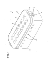
FIG. 1 is a perspective view of a connector according to a first embodiment, -
FIG. 2 is a perspective view showing a state where a housing, a one-piece rubber plug and a rubber plug holder are separated, -
FIG. 3 is a rear view of the connector, -
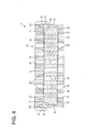
FIG. 4 is a section along A-A ofFIG. 3 , -
FIG. 5 is a section along B-B ofFIG. 3 , -
FIG. 6 is a perspective view of a connector according to a second embodiment, -
FIG. 7 is a perspective view showing a state where a housing, a one-piece rubber plug and a rubber plug holder are separated, -
FIG. 8 is a rear view of the connector, -
FIG. 9 is a section along C-C ofFIG. 8 , -
FIG. 10 is a section along D-D ofFIG. 8 , -
FIG. 11 is a perspective view of a connector according to a third embodiment, -
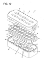
FIG. 12 is a perspective view showing a state where a housing, a one-piece rubber plug and a rubber plug holder are separated, -
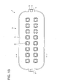
FIG. 13 is a rear view of the connector, -
FIG. 14 is a section along E-E ofFIG. 13 , and -
FIG. 15 is a section along FF ofFIG. 13 . - Hereinafter, a specific first embodiment of the present invention is described with reference to
FIGS. 1 to 5 . A connector X of this embodiment includes ahousing 10 particularly substantially in the form of a block made e.g. of synthetic resin, aresilient member 20, particularly in the form of a one-piece rubber plug 20, to be mounted in or on (particularly a rear end portion of) thehousing 10, and aresilient member holder 30, particularly in the form of arubber plug holder 30, to be mounted in or on (particularly the rear end portion of) thehousing 10. Note that, in the following description, directions are defined based on a state in which the rear end surfaces of thehousing 10, the one-piece rubber plug 20 and therubber plug holder 30 are faced up. Further, only a substantially rear half area of thehousing 10 is shown and a substantially front half area thereof is not shown. - An
accommodating recess 11 which is open backward is formed in the rear end portion of thehousing 10. The opening of theaccommodating recess 11 has a (particularly substantially rectangular or polygonal shape) whose dimension in a width direction particularly is larger than a dimension in a depth direction. Aperipheral wall portion 12 of theaccommodating recess 11 is composed of or comprises a pair of longer-side wall portions 12L along the width direction, a pair of shorter-side wall portions 12S along the depth direction, and four quarter-circulararcuate wall portions 12R (particularly substantially smoothly) connecting ends of thewall portions peripheral wall portion 12 functions as a sealing surface. Further, one or more, particularly a pair oflocking projections 13 are formed on the outer surfaces of the shorter-side wall portions 12S. - A plurality of e.g. sixteen
terminal accommodating chambers 14 are formed to penetrate through thehousing 10 in forward and backward directions in one or more rows or stages, and the rear ends of the respectiveterminal accommodating chambers 14 make openings in the back end surface of theaccommodating recess 11. The plurality of (e.g. sixteen) terminalaccommodating chambers 14 particularly substantially are so arrayed as to be linearly arranged in the width direction and/or the depth direction. In the shown example that is, theterminal accommodating chambers 14 particularly are separated in two rows in the depth direction DD, and eightterminal accommodating chambers 14 are arranged (particularly at substantially constant intervals r pitches) in the width direction WD in each row. A terminal fitting (not shown) of a known form is to be at least partly inserted into each of theseterminal accommodating chambers 14. - The resilient member 20 (particularly the one-piece rubber plug 20) substantially is shaped symmetrically with respect to forward and backward directions FBD (thickness direction TD), width direction WD and/or depth direction TD, and a dimension in the thickness direction TD (forward and backward directions FBD) of the one-
piece rubber plug 20, the opposite front and rear end surfaces of which particularly are substantially rectangular, is smaller than the depth of theaccommodating recess 11 in forward and backward directions FBD. The one-piece rubber plug 20 is mounted into thehousing 10 by being at least partly fitted (at least partly accommodated) into theaccommodating recess 11 particularly substantially from behind. In a mounted state, the front end surface of the one-piece rubber plug 20 at least partly is in contact with the back end surface of theaccommodating recess 11 and/or one or more outerperipheral lip portions 21 on the outer peripheral surface of the one-piece rubber plug 20 substantially adhere to (or are in contact with) the inner peripheral surface of theperipheral wall portion 12 in a fluid- or liquid-tight manner while being resiliently deformed. The one-piece rubber plug 20 is formed with a plurality of e.g. sixteen (particularly substantially round) wire insertion holes 22 which penetrate in forward and backward directions FBD and are arrayed in the width direction WD and/or the depth direction DD so as to substantially correspond to (conform to) the respectiveterminal accommodating chambers 14 when the one-piece rubber plug 20 is mounted into or on thehousing 10. One or more inner peripheral lips portions, the minimum inner diameter of which is smaller than the outer diameter of wires (not shown), are formed on the inner peripheries of the wire insertion holes 22. - The resilient member holder 30 (particularly the rubber plug holder 30) is made e.g. of synthetic resin and includes a main portion 31 (which particularly is in the form of a substantially rectangular or polygonal plate and/or at least partly, particularly entirely closes the rear end opening of the accommodating recess 11), and one or more, particularly a pair of
resilient locking pieces 32 which substantially project forward from themain portion 31, particularly the opposite ends of themain portion 31 in the width direction WD. An outer peripheral edge portion of the front end surface of themain portion 31 is cut off particularly substantially over the entire circumference, and a remaining area of themain portion 31 serves as afitting portion 33 to be at least partly fitted into a rear end portion ofaccommodating recess 11. Themain portion 31 is formed with a plurality of e.g. sixteen (particularly substantially rectangular) throughholes 34 which penetrate in forward and backward directions FBD (thickness direction TD) and are arrayed in the width direction WD and/or the depth direction DD to substantially correspond to (conform to) the wire insertion holes 22 and/or the terminalaccommodating chambers 14 when the resilient member holder (rubber plug holder) 30 is mounted into thehousing 10. - The
rubber plug holder 30 is to be mounted into thehousing 10 particularly substantially from behind and/or held in a mounted state by the engagement of the one or moreresilient locking pieces 32 and one ormore locking projections 13. In the mounted state of therubber plug holder 30, the front surface of thefitting portion 33 is pressed against the rear end surface of the one-piece rubber plug 20 mounted in theaccommodating recess 11, whereby the one-piece rubber plug 20 is held in the housing (accommodating recess 11) while being slightly compressed and/or prevented from coming out backward and being displaced. - Each terminal fitting is to be at least partly inserted into the terminal accommodating chamber 14 (particularly substantially from behind) while successively passing through the through
hole 34 and thewire insertion hole 22. With the terminal fitting substantially properly inserted in theterminal accommodating chamber 14, a wire connected to a rear end portion of the terminal fitting is at least partly inserted through thewire insertion hole 22 in a fluid- or liquid-tight manner and drawn out (particularly substantially backward) from therubber plug holder 30 through the throughhole 34. Since the wire particularly is thinner than the terminal fitting and the throughhole 34 is dimensioned to allow passage of the terminal fitting, a relatively large clearance is formed between the inner periphery of the throughhole 34 and the outer periphery of the wire. Thus, water (may also be another liquid or fluid) may reach the rear end surface of the one-piece rubber plug 20 from the back side of the connector X through this clearance. A means for discharging the water on the rear end surface of the one-piece rubber plug 20 is described below as a countermeasure. - A plurality of (e.g. a total of twenty)
drainage paths 23 reaching the outer peripheral edge of the one-piece rubber plug 20 from the hole edge portions of the respective wire insertion holes 22 are formed in the rear end surface of the one-piece rubber plug 20. Thedrainage paths 23 substantially are in the form of grooves or recesses which are open in the rear end surface of the one-piece rubber plug 20 and/or particularly substantially have a rectangular cross section, and/or substantially extend straight. For one or more (e.g. four) wire insertion holes 22 located at the (particularly substantially opposite) end portion(s) in the width direction, onedrainage path 23 substantially extends in the width direction WD and/or onedrainage path 23 substantially extends in the depth direction DD from the (particularly each)wire insertion hole 22. Further, for one or more (e.g. twelve) wire insertion holes 22 arranged at positions other than the opposite end portion(s) in the width direction WD, onedrainage path 23 substantially extends in the depth direction DD from the (particularly each)wire insertion hole 22. That is, thedrainage paths 23 substantially communicate with (particularly all) the wire insertion holes 22. - One or more (e.g. fourteen)
communication paths 24 which allow communication of the hole edge portions of the respective wire insertion holes 22 adjacent in the width direction WD are formed in the rear end surface of the one-piece rubber plug 20. Similar to thedrainage paths 23, thecommunication paths 24 are in the form of grooves or recesses which are open in the rear end surface of the one-piece rubber plug 20 and/or particularly substantially have a rectangular cross section, and/or particularly substantially extend straight. Similarly, one or more (e.g. eight)communication paths 24 which substantially allow communication of the hole edge portions of the wire insertion holes 22 adjacent in the depth direction DD are formed in the rear end surface of the one-piece rubber plug 20. That is, (particularly all) the wire insertion holes 22 communicate with thecommunication paths 24, wherefore (particularly each of all) thedrainage paths 23 communicates with one or morerespective communication paths 24, particularly with any one of thecommunication paths 24 via thewire insertion hole 22. Similar to thedrainage paths 23, thecommunication paths 24 particularly are in the form of grooves or recesses which are open in the rear end surface of the one-piece rubber plug 20 and/or particularly substantially have a rectangular cross section, and extend straight. - Specifically, these
drainage paths 23 andcommunication paths 24 substantially are aligned straight via the wire insertion holes 22 in the width direction WD and/or aligned straight via the wire insertion holes 22 in the depth direction DD. That is, (e.g. two) flow paths composed of thedrainage paths 23 and thecommunication paths 24 and substantially extending in the width direction WD to make openings in the outer peripheral edge of the one-piece rubber plug 20 and/or (e.g. eight) flow paths composed of thedrainage paths 23 and thecommunication paths 24 and substantially extending in the depth direction DD to make openings in the outer peripheral edge of the one-piece rubber plug 20 are formed in the rear end surface of the one-piece rubber plug 20, and the (e.g. two) flow paths substantially extending in the width direction WD and the (e.g. eight) flow paths substantially extending in the depth direction WD particularly cross at substantially right angles at the wire insertion holes 22. Note that since the one-piece rubber plug 20 particularly substantially is symmetrical with respect to forward and backward directions FBD, the same numbers ofdrainage paths 23 andcommunication paths 24 particularly are formed in the same arrangement also in the front end surface of the one-piece rubber plug 20. - One or more discharging
portions 15 which penetrate through theperipheral wall portion 12 and allow communication between the interior and exterior of theaccommodating recess 11 are formed in theperipheral wall portion 12 of thehousing 10. The dischargingportions 15 particularly are substantially rectangular openings, and/or opening areas thereof are closed over the entire circumferences like windows (i.e. not open at the rear end edge of the peripheral wall portion 12). In other words, the (particularly substantially rectangular) dischargingportions 15 are formed at a distance from an opening edge of theperipheral wall portion 12 so as to particularly have a window-like shape being closed at its sides. The dischargingportions 15 are provided at a plurality of positions (e.g. a total of twenty positions in the shown example) so as to substantially correspond to the opening ends of therespective drainage paths 23 at the outer peripheral edge of the one-piece rubber plug 20 and/or substantially located on extensions in length directions of thedrainage paths 23 and/or thecommunication paths 24. That is, one dischargingportion 15 particularly is arranged for onedrainage path 23. Further, in forward and backward directions FBD (thickness direction TD of the one-piece rubber plug 20), the opening areas of the dischargingportions 15 particularly entirely enclose the opening areas of thedrainage paths 23 in the outer peripheral surface of the one-piece rubber plug 20. That is, in forward and backward directions FBD, the rear edges of the opening edges of the dischargingportions 15 particularly are located at the substantially same positions as the rear end surface of the one-piece rubber plug 20 and/or the front edges of the opening edges of the dischargingportions 15 particularly are located before the opening areas of thedrainage paths 23 in the outer peripheral surface of the one-piece rubber plug 20. - According to the above construction, water (or any other fluid) having reached the rear end surface of the one-
piece rubber plug 20 through the throughholes 34 reaches the outer peripheral edge (outer peripheral surface) of the one-piece rubber plug 20 via various paths such as paths in which the water passes only through thedrainage path 23, paths in which the water successively passes through thewire insertion hole 22 and thedrainage path 23, paths in which the water successively passes through thecommunication path 24, thewire insertion hole 22 and thedrainage path 23, paths in which the water successively passes through thewire insertion hole 22, thecommunication path 24, anotherwire insertion hole 22 and thedrainage path 23, and/or paths in which the water passes through thedrainage path 23 after alternately passing through a plurality ofcommunication paths 24 and a plurality of wire insertion holes 22, and then is discharged to the outside of the accommodating recess 11 (housing 10) through the discharging portion(s) 15. - The connector X of this embodiment includes the
housing 10 formed with a plurality of terminalaccommodating chambers 14, theaccommodating recess 11 formed by recessing the rear end surface of thehousing 10 and communicating with the rear ends of the terminalaccommodating chambers 14, and the resilient member 20 (particularly the one-piece rubber plug 20) including a plurality of wire insertion holes 22 substantially corresponding to the terminalaccommodating chambers 14 and at least partly accommodated in theaccommodating recess 11, and the one ormore drainage paths 23 reaching the outer peripheral edge are formed in the rear end surface of the one-piece rubber plug 20. Thus, water (or any other fluid or liquid) on the rear end surface of the one-piece rubber plug 20 can be discharged from the outer peripheral edge of the one-piece rubber plug 20 via the drainage path(s) 23. Therefore, water does not stay on the rear end surface of the one-piece rubber plug 20. - Since the drainage path(s) 23 particularly communicate(s) with the hole edge portions of the wire insertion holes 22, water in the rear end portions of the wire insertion holes 22 can also be reliably discharged. Further, since the
peripheral wall portion 12 at least partly defining theaccommodating recess 11 is formed with the discharging portion(s) 15 that allow(s) communication of the drainage path(s) 23 with theperipheral wall portion 12, fluid or liquid having reached the outer peripheral edge of the one-piece rubber plug 20 via the drainage path(s) 23 is or can be reliably discharged to the outside of theaccommodating recess 11 via the discharging portion(s) 15. Further, since the one-piece rubber plug 20 particularly substantially is shaped symmetrically with respect to forward and backward directions FBD (thickness direction TD), it is not necessary to consider the forward and backward orientation of the one-piece rubber plug 20 in mounting the one-piece rubber plug 20 into theaccommodating recess 11, wherefore operability is good. - In this embodiment, another
wire insertion hole 22 particularly is present between thewire insertion hole 22 and the outer peripheral edge of the one-piece rubber plug 20 in the width direction WD. If drainage paths separately extend from these two wire insertion holes 22 toward the outer peripheral edge of the one-piece rubber plug 20, two drainage paths are necessary. In view of this point, in this embodiment, the communication path(s) 24 that allow communication of the hole edge portions of the two adjacent wire insertion holes 22 and communicate with thedrainage paths 23 via the wire insertion holes 22 are formed in the one-piece rubber plug 20. If the (particularly adjacent) two wire insertion holes 22 are allowed to communicate by thecommunication path 24, thedrainage path 23 extending from thewire insertion hole 22 closer to the outer peripheral edge of the one-piece rubber plug 20 can double as thedrainage path 23 for thewire insertion hole 22 more distant from the outer peripheral edge. Therefore, the length of the drainage path can be shortened and/or the drainage function can be improved. - Accordingly, to prevent water from staying on the rear end surface of a one-piece resilient member such as a rubber plug, a connector X includes a
housing 10 formed with a plurality of terminalaccommodating chambers 14, anaccommodating recess 11 formed by recessing the rear end surface of thehousing 10 and communicating with the rear ends of the terminalaccommodating chambers 14, and a resilient member (such as a one-piece rubber plug) 20 including a plurality of wire insertion holes 22 substantially corresponding to the terminalaccommodating chambers 14 and accommodated in theaccommodating recess 11. The one-piece rubber plug 20 is formed withdrainage paths 23 reaching from the rear end surface to the outer peripheral edge thereof. - Next, a second specific embodiment of the present invention is described with reference to
FIGS. 6 to 10 . A connector Y of this embodiment differs from the first embodiment in the forms of anaccommodating recess 41 of ahousing 40 and arubber plug holder 50 as a particular resilient member holder. Since the other constructions are similar or same as in the first embodiment, they are identified by the same reference numerals and the structures, functions and effects thereof are not described. - Although the opening areas of the discharging
portions 15 of the first embodiment are closed over the entire circumferences like window holes (i.e. not open at the rear end edge of the peripheral wall portion 12), dischargingportions 45 of the second embodiment are so formed that the rear ends of the opening areas thereof are open at the rear end edge of aperipheral wall portion 42. That is, the dischargingportions 45 particularly are substantially rectangular or polygonal cutouts made at or close to the rear end edge of theperipheral wall portion 42. Further, the depth of theaccommodating recess 41 in forward and backward directions FBD particularly is smaller than in theaccommodating recess 11 of the first embodiment, and/or the rear end surface of a one-piece rubber plug 20 (as a particular resilient member) mounted in theaccommodating recess 41 and the rear end surface of theperipheral wall portion 42 particularly are located at the same position in forward and backward directions. Amain portion 51 of therubber plug holder 50 particularly is not formed with a part corresponding to thefitting portion 33 of the first embodiment, and/or the front surface of themain portion 51 particularly is a flat surface free from any step over the entire area. The rear end surface of the one-piece rubber plug 20 is or can be pressed by the front surface of thismain portion 51. - Next, a third specific embodiment of the present invention is described with reference to
FIGS. 11 to 15 . A connector Z of this embodiment differs from the first embodiment in ahousing 60 and a rubber plug holder 70 (as a particular resilient member holder). Since the other constructions are similar or same as in the first embodiment, they are identified by the same reference numerals and the structures, functions and effects thereof are not described. - The discharging
portions 15 are formed in theperipheral wall portion 12 of theaccommodating recess 11 in the first embodiment, whereas dischargingportions 73 are formed not in aperipheral wall portion 62 of anaccommodating recess 61, but in aresilient member holder 70, particularly arubber plug holder 70, in the third embodiment. That is, the depth of theaccommodating recess 61 in forward and backward directions FBD particularly is smaller than that of theaccommodating recess 11 of the first embodiment, and/or the rear end surface of a one-piece rubber plug 20 (as a particular resilient member) at least partly mounted in theaccommodating recess 61 is located to project backward from the rear end surface of theperipheral wall portion 62. An outerfitting portion 72 particularly is formed over the substantially entire circumference on the front surface of amain portion 71 of therubber plug holder 70. The outerfitting portion 72 projects forward like a rib or projection (wall) particularly substantially along the outer peripheral edge of themain portion 71. One or more (particularly substantially rectangular or polygonal) cutouts are formed in a front end edge portion of this outerfitting portion 72 to form the one or more dischargingportions 73. - With the
rubber plug holder 70 mounted in thehousing 60, the front end of the outerfitting portion 72 particularly substantially is in contact with the rear end of theperipheral wall portion 62 and/or the front surface of themain portion 71 particularly substantially presses the rear end surface of the one-piece rubber plug 20. Further, the outerfitting portion 72 surrounds a rear end portion of the one-piece rubber plug 20 projecting backward from the rear end of theperipheral wall portion 62 over at least part of the circumference, particularly substantially over the entire circumference. The discharging portion(s) 73 formed in the outerfitting portion 72 is/are located to substantially correspond to respective drainage path(s) 23 on the rear end surface of the one-piece rubber plug 20. - In the third embodiment, paying attention to the fact that the one-
piece rubber plug 20 particularly is symmetric with respect to forward and backward directions FBD and thedrainage paths 23 andcommunication paths 24 in the form of grooves particularly are formed also in the front end surface of the one-piece rubber plug 20, a plurality ofprojections 63 substantially corresponding to thedrainage paths 23 and thecommunication paths 24 particularly are formed in the back end surface of theaccommodating recess 61. With therubber plug holder 70 mounted in thehousing 60, thedrainage paths 23 and thecommunication path 24 are correspond to or engaged with theprojections 63, thereby particularly preventing displacements of the front end portion of the one-piece rubber plug 20 relative to theaccommodating recess 61 in the width direction WD and/or the depth direction DD and/or improper resilient deformations thereof. In this way, the front openings of wire insertion holes 22 are positioned to maintain a proper positional relationship with the rear openings of terminalaccommodating chambers 14. - The present invention is not limited to the above described and illustrated embodiments. For example, the following embodiments are also included in the technical scope of the present invention.
- (1) Although the drainage paths are in the form of grooves which are entirely open in the rear end surface of the one-piece rubber plug in the above first to third embodiments, they may be such that the opposite ends are open in the rear end surface and at the outer peripheral edge of the one-piece rubber plug and the other areas are located in the one-piece rubber plug.
- (2) Although all the drainage paths communicate with the hole edge portions of the wire insertion holes in the above first to third embodiments, all the drainage paths may not communicate with the hole edge portions of the wire insertion holes and only some of a plurality of drainage paths may communicate with the hole edge portions of the wire insertion holes.
- (3) Although the drainage paths are straight in the above first to third embodiments, they may be curved or bent.
- (4) Although the hole edge portions of all the pairs of wire insertion holes in an adjacent positional relationship in the width direction or the depth direction communicate with each other via the communication paths in the above first to third embodiments, some pairs of wire insertion holes in such a positional relationship may not communicate with each other via the communication paths.
- (5) Although two wire insertion holes in an adjacent positional relationship in the width direction or the depth direction communicate with each other via the communication path in the above first to third embodiments, two wire insertion holes adjacent in a diagonal direction may communicate with each other via the communication path.
- (6) Although the communication paths are straight in the above first to third embodiments, they may be curved or bent.
- (7) Although the communication paths that allow communication between two adjacent wire insertion holes are formed in the above first to third embodiments, such communication paths may not be formed.
- (8) Although the communication paths and the drainage paths are linearly arranged in the above first to third embodiments, the communication paths and the drainage paths may be diagonally arranged and positioned to each other.
- (9) Although the drainage paths and the communication paths communicate via the wire insertion holes in the above first to third embodiments, the drainage paths and the communication paths may directly communicate. In this case, the drainage paths may be branched off from the communication paths or cross the communication paths.
- (10) Although one discharging portion is provided for one drainage path in the above first to third embodiments, one discharging portion may correspond to a plurality of drainage paths.
- (11) Although a plurality of wire insertion holes are arranged in a matrix in the width direction and the depth direction in the above first to third embodiments, they may be arranged in an offset manner.
- (12) Although the one-piece rubber plug is shaped symmetrically with respect to forward and backward directions in the above first to third embodiments, it may be shaped asymmetrically with respect to forward and backward directions. In this case, neither the drainage paths nor the communication paths may be formed in the front surface of the one-piece rubber plug in the first and second embodiments and the positions of the drainage paths and the communication paths may be made different in the front and rear surfaces in the third embodiment.
- (13) The configuration of the third embodiment to engage the drainage paths and the projections is also applicable to the first and second embodiments.
- (14) The configuration of the third embodiment to engage the communication paths and the projections is also applicable to the first and second embodiments.
- (15) The configuration of the third embodiment to form the discharging portions in the rubber plug holder is applicable to the second embodiment. In this case, one discharging portion can be formed by uniting the discharging portion of the rubber plug holder and the discharging portion of the peripheral wall portion.
- (16) Although sixteen terminal accommodating chambers and wire insertion holes are formed in the above first to third embodiments, the numbers of the terminal accommodating chambers and the wire insertion holes may be fifteen or less or seventeen or more.
- (17) Although the terminal accommodating chambers and the wire insertion holes are arranged in two separate rows in the depth direction in the above embodiments, the number of rows in the depth direction may be one, three or more.
- (18) Although eight terminal accommodating chambers and eight wire insertion holes are arranged in the width direction in the above first to third embodiments, the numbers of the terminal accommodating chambers and the wire insertion holes in the width direction may be seven or less or nine or more.
- (19) Although the resilient member has been described in the above embodiments to particularly be a one-piece rubber plug, it should be understood that the resilient member may be formed in several pieces and/or be made of a resilient material different from rubber such as a gelatinous or elastic material which may be a gel or elastic or rubbery material containing three dimensional cross-linked molecular formations or behave as if it contained such molecular formations (geloids). One example of a gel that can be used is silicone gel or resin. Another suitable gel comprises a block copolymer having relatively hard blocks (e.g. hydrogenated rubber blocks) examples of such copolymers including styrene-diene block copolymers (linear or radial) for example styrene-butadiene or styrene-isoprene diblock or triblock copolymers, or styrene-ethylene-butylene-styrenes triblock copolymers. The gel may be formed from a single liquid material which becomes a gel when subjected e.g. to radiation or chemicals; the gel may be formed from two components which become a gel when mixed; or the gel may be a composition which is a gel at working temperature, e.g. room temperature. Additionally or alternatively a gel material as disclosed in
US-A-4 875 870 may be used, which is included herein by reference. -
- X ...
- connector
- 10 ...
- housing
- 11 ...
- accommodating recess
- 12 ...
- peripheral wall portion
- 14 ...
- terminal accommodating chamber
- 15 ...
- discharging portion
- 20 ...
- one-piece rubber plug (resilient member)
- 22 ...
- wire insertion hole
- 23 ...
- drainage path
- 24 ...
- communication path
- Y, Z ...
- connector
- 40, 60...
- housing
- 41, 61 ...
- accommodating recess
- 42, 62...
- peripheral wall portion
- 45, 73...
- discharging portion
- 63 ...
- projection
- 72 ...
- outer fitting portion
Claims (13)
- A connector (X; Y; Z), comprising:a housing (10; 40; 60) formed with a plurality of terminal accommodating chambers (14);at least one accommodating recess (11; 41; 61) formed by recessing the rear end surface of the housing (10; 40; 60) and communicating with the rear ends of the terminal accommodating chambers (14); anda resilient member (20) including a plurality of wire insertion holes (22) substantially corresponding to the terminal accommodating chambers (14) and to be at least partly accommodated in the accommodating recess (11; 41; 61);wherein the resilient member (20) is formed with at least one drainage path (23) reaching from the rear end surface to the outer peripheral edge thereof.
- A connector according to claim 1, wherein the drainage path (23) communicates with hole edge portions of the wire insertion holes (22).
- A connector according to any one of the preceding claims, wherein the resilient member (20) is formed with at least one communication path (24) which allows communication between the hole edge portions of two wire insertion holes (22) and communicates with the drainage path (23) via the wire insertion holes (22) and/or with the outer peripheral edge of the resilient member (20).
- A connector according to any one of the preceding claims, wherein a peripheral wall portion (12; 42; 62) at least partly defining the accommodating recess (11; 41; 61) is formed with at least one discharging portion (15; 45; 73) which allows the drainage path (23) and/or the communication path (24) to communicate with the outer surface of the peripheral wall portion (15; 45; 73).
- A connector according to any one of the preceding claims, wherein the resilient member (20) is shaped symmetrically with respect to forward and backward directions (FBD).
- A connector according to any one of the preceding claims, wherein at least one projection (63) to be engaged with the resilient member (20), preferably with the drainage path (23), is formed on the back end surface of the accommodating recess (61).
- A connector according to any one of the preceding claims, wherein the drainage path (23) substantially is in the form of a groove which is open in a rear end surface of the resilient member (20) and preferably substantially has a rectangular or polygonal cross section, and/or preferably substantially extends straight.
- A connector according to any one of the preceding claims, further comprising a resilient member holder (30; 50; 70) to be mounted on the housing (10; 40; 60) to hold the resilient member (20) preferably in a slightly compressed state.
- A connector according to claim 8, wherein the resilient member holder (30; 50; 70) includes a main portion (31; 51; 71) being provided with at least one through hole (34) which penetrates the main portion (31; 51; 71) in thickness direction (TD) and substantially corresponds to the wire insertion hole (22).
- A connector according to claim 8 or 9, wherein the resilient member holder (30; 50; 70) at least partly, particularly entirely closes the rear end opening of the accommodating recess (11; 41; 61),
- A connector according to any one of the preceding claims, wherein the resilient member (20) is made of rubber or gelatinous material.
- A connector according to any one of the preceding claims, wherein the resilient member (20) comprises at least one outer peripheral lip portion (21) on its outer peripheral surface which are provided to substantially adhere to an inner peripheral surface of the peripheral wall portion (12; 42; 62) in a fluid- or liquid-tight manner when the resilient member (20) is at least partly accommodated in the accommodating recess (11; 41; 61).
- A connector according to any one of the preceding claims, wherein at least one inner peripheral lips portion is formed on the inner periphery of the wire insertion hole (22) having a minimum inner diameter which is smaller than the outer diameter of a wire to be inserted into the wire insertion hole (22).
Applications Claiming Priority (1)
| Application Number | Priority Date | Filing Date | Title |
|---|---|---|---|
| JP2011024093A JP5644563B2 (en) | 2011-02-07 | 2011-02-07 | connector |
Publications (1)
| Publication Number | Publication Date |
|---|---|
| EP2485339A1 true EP2485339A1 (en) | 2012-08-08 |
Family
ID=45531760
Family Applications (1)
| Application Number | Title | Priority Date | Filing Date |
|---|---|---|---|
| EP12000371A Withdrawn EP2485339A1 (en) | 2011-02-07 | 2012-01-20 | Connector |
Country Status (4)
| Country | Link |
|---|---|
| US (1) | US8647132B2 (en) |
| EP (1) | EP2485339A1 (en) |
| JP (1) | JP5644563B2 (en) |
| CN (1) | CN102629718B (en) |
Cited By (1)
| Publication number | Priority date | Publication date | Assignee | Title |
|---|---|---|---|---|
| EP4346020A1 (en) * | 2022-09-30 | 2024-04-03 | Tyco Electronics Japan G.K. | Waterproof connector and waterproofing element |
Families Citing this family (18)
| Publication number | Priority date | Publication date | Assignee | Title |
|---|---|---|---|---|
| JP5923898B2 (en) * | 2011-08-30 | 2016-05-25 | ブラザー工業株式会社 | Development device |
| JP2014086144A (en) * | 2012-10-19 | 2014-05-12 | Yazaki Corp | Terminal connection structure of electrical wire |
| JP6032224B2 (en) * | 2014-02-24 | 2016-11-24 | 株式会社デンソー | Electrical connector and manufacturing method thereof |
| ES2768272T3 (en) * | 2014-03-05 | 2020-06-22 | Yazaki Europe Ltd | Molding tool |
| DE102014008853B4 (en) * | 2014-06-14 | 2016-05-04 | Audi Ag | Plastic-coated conductor track structure and method for producing the plastic-coated conductor track structure |
| JP6209551B2 (en) * | 2015-03-30 | 2017-10-04 | 矢崎総業株式会社 | Connector and manufacturing method thereof |
| JP6431471B2 (en) * | 2015-12-22 | 2018-11-28 | 矢崎総業株式会社 | Sealing member and connector |
| US10044132B2 (en) | 2016-04-22 | 2018-08-07 | Yazaki North America, Inc. | Cable seal connector with punch-out capability for unused cavities |
| US11121502B2 (en) * | 2016-09-23 | 2021-09-14 | Apple Inc. | Magnetic connectors |
| JP6860823B2 (en) * | 2017-06-21 | 2021-04-21 | 住友電装株式会社 | Waterproof connector |
| JP6840636B2 (en) * | 2017-07-19 | 2021-03-10 | 日本航空電子工業株式会社 | Waterproof connector |
| CN110011110B (en) * | 2018-01-05 | 2024-10-29 | 泰科电子(上海)有限公司 | Pluggable wire-to-wire connector |
| JP7022335B2 (en) * | 2018-05-16 | 2022-02-18 | 住友電装株式会社 | connector |
| US11283211B2 (en) | 2018-05-18 | 2022-03-22 | Yazaki North America, Inc. | Electrical connector assembly with plug and cavity assembly and method of ultrasonically welding |
| US10777934B2 (en) * | 2018-07-16 | 2020-09-15 | Te Connectivity Corporation | Electrical connector which accepts different seal configurations |
| EP3629426A1 (en) * | 2018-09-27 | 2020-04-01 | Tyco Electronics Japan G.K. | Seal member and connector assembly |
| US11735858B2 (en) * | 2020-07-14 | 2023-08-22 | J.S.T. Corporation | Elastomer seal spring |
| US12266885B2 (en) * | 2022-12-12 | 2025-04-01 | Aptiv Technologies AG | Seal retainer with seal expansion compensation features |
Citations (6)
| Publication number | Priority date | Publication date | Assignee | Title |
|---|---|---|---|---|
| US4875870A (en) | 1987-07-16 | 1989-10-24 | Raychem Limited | Article for protecting a substrate |
| US5634807A (en) * | 1994-03-24 | 1997-06-03 | Yazaki Corporation | Waterproof structure of connector |
| US5811728A (en) * | 1994-03-18 | 1998-09-22 | Yazaki Corporation | Waterproof rubber tap and waterproof connector |
| US5931699A (en) * | 1996-04-19 | 1999-08-03 | Yazaki Corporation | Waterproof connector |
| JP2001299156A (en) | 2000-04-26 | 2001-10-30 | Soft Hanzu:Kk | Fishing rod |
| JP2004328842A (en) * | 2003-04-22 | 2004-11-18 | Yazaki Corp | Electrical junction box |
Family Cites Families (17)
| Publication number | Priority date | Publication date | Assignee | Title |
|---|---|---|---|---|
| JPS56105272U (en) * | 1980-01-14 | 1981-08-17 | ||
| JP2503949Y2 (en) * | 1990-06-29 | 1996-07-03 | 矢崎総業株式会社 | Waterproof connector |
| US5145410A (en) * | 1990-08-06 | 1992-09-08 | Yazaki Corporation | Waterproof connector |
| IT1270371B (en) * | 1993-05-21 | 1997-05-05 | Framatome Connectors Italia | ELECTRIC CONNECTOR |
| JP2788598B2 (en) * | 1993-12-03 | 1998-08-20 | 矢崎総業株式会社 | Waterproof rubber stopper and waterproof connector |
| JP3050751B2 (en) * | 1994-07-07 | 2000-06-12 | 矢崎総業株式会社 | Waterproof rubber stopper |
| JPH08180928A (en) * | 1994-10-24 | 1996-07-12 | Yazaki Corp | Waterproof connector |
| JP4163263B2 (en) * | 1995-04-06 | 2008-10-08 | 矢崎総業株式会社 | Waterproof connector |
| JP3175817B2 (en) * | 1996-04-05 | 2001-06-11 | 矢崎総業株式会社 | Waterproof connector |
| JP2000082528A (en) * | 1998-09-04 | 2000-03-21 | Kansei Corp | Waterproof connector |
| DE60026234T2 (en) | 1999-04-13 | 2006-12-14 | Sumitomo Wiring Systems, Ltd., Yokkaichi | Interconnects |
| US7077667B2 (en) * | 2003-04-22 | 2006-07-18 | Yazaki Corporation | Electrical junction box |
| JP4536361B2 (en) * | 2003-11-28 | 2010-09-01 | 株式会社日立製作所 | Data transfer apparatus, storage device control apparatus, and storage device control apparatus control method |
| JP2005317385A (en) * | 2004-04-28 | 2005-11-10 | Tyco Electronics Amp Kk | Waterproof connector and sealing member therefor |
| US7371115B1 (en) * | 2006-12-15 | 2008-05-13 | Delphi Technologies, Inc. | Mat seal device |
| JP4881805B2 (en) * | 2007-07-12 | 2012-02-22 | 矢崎総業株式会社 | Waterproof connector |
| JP2008204960A (en) * | 2008-05-28 | 2008-09-04 | Sumitomo Wiring Syst Ltd | Waterproof connector |
-
2011
- 2011-02-07 JP JP2011024093A patent/JP5644563B2/en not_active Expired - Fee Related
-
2012
- 2012-01-20 EP EP12000371A patent/EP2485339A1/en not_active Withdrawn
- 2012-01-26 US US13/358,607 patent/US8647132B2/en not_active Expired - Fee Related
- 2012-01-31 CN CN201210021804.0A patent/CN102629718B/en not_active Expired - Fee Related
Patent Citations (6)
| Publication number | Priority date | Publication date | Assignee | Title |
|---|---|---|---|---|
| US4875870A (en) | 1987-07-16 | 1989-10-24 | Raychem Limited | Article for protecting a substrate |
| US5811728A (en) * | 1994-03-18 | 1998-09-22 | Yazaki Corporation | Waterproof rubber tap and waterproof connector |
| US5634807A (en) * | 1994-03-24 | 1997-06-03 | Yazaki Corporation | Waterproof structure of connector |
| US5931699A (en) * | 1996-04-19 | 1999-08-03 | Yazaki Corporation | Waterproof connector |
| JP2001299156A (en) | 2000-04-26 | 2001-10-30 | Soft Hanzu:Kk | Fishing rod |
| JP2004328842A (en) * | 2003-04-22 | 2004-11-18 | Yazaki Corp | Electrical junction box |
Cited By (1)
| Publication number | Priority date | Publication date | Assignee | Title |
|---|---|---|---|---|
| EP4346020A1 (en) * | 2022-09-30 | 2024-04-03 | Tyco Electronics Japan G.K. | Waterproof connector and waterproofing element |
Also Published As
| Publication number | Publication date |
|---|---|
| JP2012164524A (en) | 2012-08-30 |
| JP5644563B2 (en) | 2014-12-24 |
| US8647132B2 (en) | 2014-02-11 |
| CN102629718A (en) | 2012-08-08 |
| CN102629718B (en) | 2014-10-29 |
| US20120202368A1 (en) | 2012-08-09 |
Similar Documents
| Publication | Publication Date | Title |
|---|---|---|
| US8647132B2 (en) | Connector with fluid discharge hole in housing and fluid drainage path in seal | |
| US10193258B2 (en) | Two piece clean body female electric terminal | |
| JP4259453B2 (en) | Waterproof connector | |
| US7601035B2 (en) | Connector | |
| JP2002170622A (en) | connector | |
| US6244898B1 (en) | Waterproof connector | |
| US7581969B2 (en) | Connector with auxiliary housing having inverted insertion preventing portion | |
| CN109103679A (en) | Water-proof connector | |
| JP2007005239A (en) | Connector | |
| US20090142958A1 (en) | Connector | |
| CN102195186B (en) | Connector | |
| US20060134949A1 (en) | Electrical connector with protective cover for post header | |
| JP2017117571A (en) | Seal member and connector | |
| US6589080B2 (en) | Terminal fitting and a connector | |
| US10804641B2 (en) | Electrical connector having a metallic inner shell with rear engaging finger situated within an insulative outer cover | |
| US20200251851A1 (en) | Elastic member and waterproof connector | |
| EP2706618A2 (en) | Connector | |
| US20210104841A1 (en) | Terminal fitting | |
| JP5083012B2 (en) | Waterproof connector | |
| JP3367463B2 (en) | Joint connector | |
| JP4904131B2 (en) | connector | |
| US6648685B2 (en) | Connector | |
| JP2009158262A (en) | Connector | |
| JP6879244B2 (en) | connector | |
| JP4826520B2 (en) | connector |
Legal Events
| Date | Code | Title | Description |
|---|---|---|---|
| PUAI | Public reference made under article 153(3) epc to a published international application that has entered the european phase |
Free format text: ORIGINAL CODE: 0009012 |
|
| AK | Designated contracting states |
Kind code of ref document: A1 Designated state(s): AL AT BE BG CH CY CZ DE DK EE ES FI FR GB GR HR HU IE IS IT LI LT LU LV MC MK MT NL NO PL PT RO RS SE SI SK SM TR |
|
| AX | Request for extension of the european patent |
Extension state: BA ME |
|
| 17P | Request for examination filed |
Effective date: 20121220 |
|
| 17Q | First examination report despatched |
Effective date: 20140807 |
|
| STAA | Information on the status of an ep patent application or granted ep patent |
Free format text: STATUS: THE APPLICATION IS DEEMED TO BE WITHDRAWN |
|
| 18D | Application deemed to be withdrawn |
Effective date: 20141218 |