EP2485205B1 - Systems and methods for providing ITP clearance information - Google Patents
Systems and methods for providing ITP clearance information Download PDFInfo
- Publication number
- EP2485205B1 EP2485205B1 EP11192022.9A EP11192022A EP2485205B1 EP 2485205 B1 EP2485205 B1 EP 2485205B1 EP 11192022 A EP11192022 A EP 11192022A EP 2485205 B1 EP2485205 B1 EP 2485205B1
- Authority
- EP
- European Patent Office
- Prior art keywords
- transition
- aircraft
- information
- itp
- valid
- Prior art date
- Legal status (The legal status is an assumption and is not a legal conclusion. Google has not performed a legal analysis and makes no representation as to the accuracy of the status listed.)
- Not-in-force
Links
- 238000000034 method Methods 0.000 title claims description 23
- 230000007704 transition Effects 0.000 claims description 54
- 238000000926 separation method Methods 0.000 description 20
- 238000002310 reflectometry Methods 0.000 description 7
- 230000001419 dependent effect Effects 0.000 description 2
- 230000000903 blocking effect Effects 0.000 description 1
- 238000010586 diagram Methods 0.000 description 1
- 230000000694 effects Effects 0.000 description 1
- 238000000605 extraction Methods 0.000 description 1
- 230000002349 favourable effect Effects 0.000 description 1
- 238000001914 filtration Methods 0.000 description 1
- 230000010006 flight Effects 0.000 description 1
- 230000033001 locomotion Effects 0.000 description 1
- 230000008520 organization Effects 0.000 description 1
Images





Classifications
-
- G—PHYSICS
- G08—SIGNALLING
- G08G—TRAFFIC CONTROL SYSTEMS
- G08G5/00—Traffic control systems for aircraft
- G08G5/20—Arrangements for acquiring, generating, sharing or displaying traffic information
- G08G5/25—Transmission of traffic-related information between aircraft
-
- G—PHYSICS
- G08—SIGNALLING
- G08G—TRAFFIC CONTROL SYSTEMS
- G08G5/00—Traffic control systems for aircraft
- G08G5/20—Arrangements for acquiring, generating, sharing or displaying traffic information
- G08G5/21—Arrangements for acquiring, generating, sharing or displaying traffic information located onboard the aircraft
-
- G—PHYSICS
- G08—SIGNALLING
- G08G—TRAFFIC CONTROL SYSTEMS
- G08G5/00—Traffic control systems for aircraft
- G08G5/30—Flight plan management
- G08G5/32—Flight plan management for flight plan preparation
-
- G—PHYSICS
- G08—SIGNALLING
- G08G—TRAFFIC CONTROL SYSTEMS
- G08G5/00—Traffic control systems for aircraft
- G08G5/30—Flight plan management
- G08G5/34—Flight plan management for flight plan modification
-
- G—PHYSICS
- G08—SIGNALLING
- G08G—TRAFFIC CONTROL SYSTEMS
- G08G5/00—Traffic control systems for aircraft
- G08G5/70—Arrangements for monitoring traffic-related situations or conditions
- G08G5/72—Arrangements for monitoring traffic-related situations or conditions for monitoring traffic
- G08G5/723—Arrangements for monitoring traffic-related situations or conditions for monitoring traffic from the aircraft
-
- G—PHYSICS
- G08—SIGNALLING
- G08G—TRAFFIC CONTROL SYSTEMS
- G08G5/00—Traffic control systems for aircraft
- G08G5/70—Arrangements for monitoring traffic-related situations or conditions
- G08G5/76—Arrangements for monitoring traffic-related situations or conditions for monitoring atmospheric conditions
Definitions
- Climbs or descents provide optimal performance to take advantage of favorable winds or to avoid turbulence or other weather anomalies.
- ADS-B Automatic dependent surveillance-broadcast
- ITP in-trail procedures
- ITP is airborne ADS-B-enabled climbs and descents through otherwise blocked flight levels.
- ITP is based on an approved International Civil Aviation Organization (ICAO) procedure whereby a controller separates aircraft based on information derived from cockpit sources that is relayed by the flight crew.
- IAO International Civil Aviation Organization
- ITP allows a leading or following aircraft on the same track to climb or descend to a desired flight level through flight levels occupied by other aircraft at separation distances less than those required for a standard (STD) climb/descent procedure.
- An ITP display enables a flight crew to determine if specific criteria for an ITP climb/descent are met with respect to one or two reference aircraft at intervening flight levels. These criteria ensure that the spacing between the estimated positions of the ITP aircraft and reference aircraft always exceeds the ITP separation minimum of 10 NM, while vertical separation does not exist during the climb or descent. Once the flight crew has established that the ITP criteria are met, they request an ITP climb or descent, identifying any reference aircraft in the clearance request.
- Air Traffic Control must determine if standard separation will be met for all aircraft at the requested flight level -- and at all flight levels between the initial flight level and the requested flight level. If so, a standard (non-ITP) flight level change clearance is likely to be granted. Otherwise, if the reference aircraft are the only blocking aircraft, the controller evaluates the ITP request. ATC determines if the reference aircraft have been cleared to change speed or change flight level or are about to reach a point at which a significant change of track will occur. The controller also ensures that the requesting aircraft is not referenced in another procedure. ATC also ensures that the positive Mach difference with the reference aircraft is no greater than 0.06 Mach. If each of these criteria is satisfied, then ATC may issue the ITP flight level change clearance.
- US 2010/0286900 A1 discloses a method to help an aircraft to altitude change in case of reduced separations.
- US 2011/0006918 A1 discloses a method for filtering and presenting relevant aircraft traffic to a pilot.
- the present invention provides methods and systems for providing improved In-Trails Procedure (ITP) and standard (STD) transition information on a display with a vertical profile view.
- ITP In-Trails Procedure
- STD standard transition information
- a user interface located on a host aircraft receives a user selection of a desired altitude.
- a processor on the host aircraft receives information from one or more proximate target aircraft via a communications system on the host aircraft and receives host aircraft information from one or more other systems located on the host aircraft.
- the processor generates a graphical user interface display for presentation on a display coupled to the processing device.
- the graphical user interface display includes a vertical profile view that shows a valid or invalid indication for an In-Trails Procedure (ITP) and standard (STD) transition to the altitude associated with the received desired altitude based on the received proximate target aircraft and host aircraft information.
- ITP In-Trails Procedure
- STD standard
- the indication presents time and/or distance information and a position informations of when and where the ITP transition and the STD transition to the altitude associated with the received desired altitude will be valid or will cease to be valid.
- FIGURE 1 illustrates an embodiment of a system for providing improved in-trail procedures (ITP) functionality on an aircraft 20.
- the exemplary system includes a weather radar system 40 (optional) and a processor 24 that is in signal communication with the weather radar system 40, an automatic dependent surveillance-broadcast (ADS-B) system 26, a traffic collision avoidance system (TCAS) 28 (optional), a display device with a user interface 30, a communications system 32, and memory 34.
- the processor 24 may be connected to other aircraft systems 46, such as a Global Positioning System (GPS) or comparable device, for retrieving various flight information (e.g., position and speed information).
- GPS Global Positioning System
- the processor 24 receives information of other aircraft in the vicinity of the aircraft 20 via the ADS-B system 26 and, if included, the TCAS 28.
- the TCAS 28 includes the ADS-B functionality and the processor 24 is included in the TCAS 28.
- the processor 24 presents the received other aircraft (target) information on the display device and user interface 30. Pilots interact with the processor 24 using the user interface 30, such as a cursor control device or a touch-screen display, for analyzing and sending ITP change of altitude requests to a controller authority via the communications system 32. This will be shown in more detail below in the following figures.
- An example of the radar system 40 includes a radar controller 50, a transmitter 52, a receiver 54, and an antenna 56.
- the radar controller 50 controls the transmitter 52 and the receiver 54 for performing the sending and receiving of signals through the antenna 56.
- the weather radar system 40 and the processor 24 are in signal communication with the other aircraft systems 46.
- the radar controller 50 or comparable processor calculates the distance of weather objects (target 60) relative to the antenna 56, based upon the length of time the transmitted signal pulse takes in the transition from the antenna 56 to the target 60 and back to the antenna 56 (i.e., reflectivity signal).
- the relationship between distance and time is linear as the velocity of the signal is constant, approximately the speed of light in a vacuum.
- the memory 34 includes a three-dimensional volumetric buffer for storing the reflectivity data from the receiver 54.
- the processor 24 has the capabilities of inferring lightning, hail, or turbulence based on the reflectivity data stored in the volumetric buffer.
- the processor 24, having access to the volumetric buffer, provides weather and wake vortex information to the ITP display device 30.
- An exemplary weather radar system 40 is Honeywell's IntuVueTM Weather Radar, which encompasses a three-dimensional volumetric buffer.
- the radar system 40 continuously scans the entire three-dimensional space in front of the aircraft 20 and stores all reflectivity data in an earth-referenced, three-dimensional (or "volumetric") memory buffer (memory 34).
- the buffer is continuously updated with reflectivity data from new scans.
- the data stored in the buffer are compensated for aircraft movement (speed, heading, altitude).
- the data in the buffer are updated at a rate of every 30 seconds, for example.
- the three-dimensional method employs a scanning scheme that provides full coverage over a total of -15 to +15 degrees tilt control range.
- Reflectivity data are extracted from the buffer to generate the desired display views without having to make (and wait for) view-specific antenna scans. In one embodiment, this extraction and image generation are performed at one-second intervals (compared to four seconds for conventional radar). With the three-dimensional volumetric buffer data, the display presentation is not constrained to a single tilt-plane that is inherent to conventional radar.
- the processor 24 generates an ITP vertical profile view that is presented on a vertical situation awareness display (VSAD) and/or three-dimensional display device (the display device 30).
- the ITP vertical profile view includes:
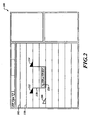
- FIGURE 2 illustrates an exemplary ITP display 100 that shows in a vertical profile view section 102 an own-ship symbol 106 presented approximately in the middle vertically of the vertical profile view section 102.
- the pilot has selected (using the user interface 30) an altitude to which they desire to transition. This desired altitude is indicated by the dashed altitude line 110.
- the processor 24 determines if an ITP or STD climb procedure is available out to a predefined (or user selectable) distance from the present position of the aircraft 20.
- the processor 24 has determined that an ITP or STD climb to the desired altitude is not possible in the column of space between the aircraft associated with the other aircraft icons 112, 114 due to information received from those other aircraft and the own-ship's current flight information.
- the processor 24 receives flight information from the aircraft associated with the other aircraft icons 112, 114 via the ADS-B system 26 and the own-ship information via the other aircraft systems 46 in order to determine if an ITP or STD transition is possible within the column of space between the two aircraft (icons 112, 114). This determination can be made for other columns of space not occupied by other aircraft. Some of the information that the processor 24 uses in order to make this determination includes the location and current airspeeds of the other aircraft as well as the current airspeed of the own-ship 20.
- the indication displayed on the vertical profile view section 102 that indicates that there is no STD or ITP separation, in order to perform a transition to the desired altitude, includes a box or a partial box 118 that links the two other aircraft icons 112, 114 and within that box 118 is a text window 120 that includes text stating that no STD or ITP separation exists.
- FIGURE 3 illustrates an example that is similar to that shown in FIGURE 2 , except that the processor 24 has determined that the volume of space between the two other aircraft does provide adequate ITP separation in order to perform the transition to the desired altitude. This is indicated by the text within the text window 120 indicating that ITP separation is okay. In one embodiment, the color and/or shading of the text window 120 when ITP (or STD) separation is valid are different from those when ITP (or STD) separation is not okay (see FIGURE 2 ).
- the lower left corner of the linking box 118 is uniquely identified with an icon 134 and a time and/or distance window 136, if ITP separation does not currently exist but will exist at some time in the future, as determined by the processor 24, based on all the received information.
- the time and/or distance window 136 identifies either a countdown of time as to when the volume of space between the two other aircraft will provide a valid ITP separation or the amount of distance that the current aircraft must travel before the ITP separation for the volume of space between the two other aircraft is valid.
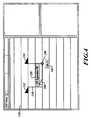
- FIGURE 4 illustrates a situation where the own-ship (the icon 106) is within the volume of space between two other aircraft and the pilot of the own-ship has selected a desired altitude that is above the other aircraft.
- the text window 120 within the linking box 118 indicates that ITP separation is valid/okay.
- the processor 24 calculates when an ITP climb associated with the column of space identified by the linking box 118 will no longer be valid.
- the position where the ITP climb is determined to no longer be valid is identified visually by an icon 140 located in the bottom-right corner of the linking box 118.
- Adjacent (e.g., below) the linking box 118 is an associated time or distance window 142 that presents the calculated time or distance at which an ITP climb will no longer be valid.
- FIGURE 5 illustrates a situation where the processor 24 determines that a volume of space between other aircraft is valid for a transition to a desired altitude for an own-ship, as indicated by the own-ship icon 106, at different times for an STD transition than for an ITP transition.
- the linking box 118 includes a first text box 130 that indicates that the STD separation is okay and a second text box 132 that indicates that the ITP separation is okay. In one embodiment, these two text boxes 130, 132 are identified with different shading and/or color.
- FIGURE 6 is similar to FIGURE 5 , except that the STD separation text box 130 includes an icon 148 at its lower-left corner and a time/distance window 150 is displayed below the icon 148.
- the time/distance window 150 indicates the time and/or distance when the associated STD transition to the desired altitude is valid.
- the second text window 132 includes an icon 154 at the lower-left corner and an associated time/distance window 156 that indicates time and/or distance when the ITP transition between the two other aircraft is valid to the desired altitude.
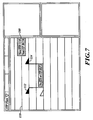
- FIGURE 7 presents a message box 160 at the far-right end of the selected desired altitude line 110 for indicating when the next STD and/or ITP transition is valid outside of the range visibly present within the vertical profile view section 102.
- the message box 160 indicates either time or distance as to when the next STD or ITP transition is valid.
- the color or shading of the message box 160 is similar to that for the valid indication, such as that shown in the text window 120 of FIGURE 4 .
- the message box 160 is presented only when there does not exist a valid STD or ITP transition within the currently viewed vertical profile view section 102.
- a time/distance scale 170 that includes a timeline or distance locator icon 172.
- the vertical profile view sectoin 102 shows the own-ship icon 106 ( FIGURE 2 ) and any other icons associated with other aircraft or weather anomalies that would fit within the scale of the vertical profile view section 102 relative to the own-ship's current position.
- the vertical profile view section 102 presents any icons associated with aircraft and/or weather and any valid (or invalid) STD or ITP transitions to the desired altitude, such as that described above, based on a time or distance of the icon 172 from the own-ship's current position.
- the locator icon 172 can be manipulated by the pilot in order to show what is ahead of the aircraft when the pilot activates the locator icon 172 and slides it along the time/distance scale 170.
- a text window 174 appears above the locator icon 172 to indicate the location of the contents (aircraft, weather) currently displayed in the vertical profile view section 102. The indicated location in the text window 174 is relative to the own-ship's current location.
- the icon 172 and the current contents of the vertical profile view section 102 are located 550 nautical miles (NM) or 1.1 hours from the present position (pp) of the own-ship.
- a message box 162 shows when the next ITP transition will be valid.
- the message box 162 is presented in a similar location as message box 160 shown in FIGURE 7 .
- the values located in the message box 162 are relative to the own-ship's current location.
- the next STD valid transition is not presented because there exists a valid STD transition as indicated by a text window 164 that is included within a linking box 166 between two other aircraft icons 168, 169.
- the STD transition is not valid until some distance after the location of the left aircraft (the icon 168).
- the leading edge of the linking box 166 is located at some distance between the two icons 168, 169.
- the distance where the leading edge (or trailing edge) is located is where the STD transition is valid, as determined by the processor 24.
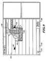
- the icon 172 has been located along the timeline 170 at a point where a valid STD transition is presented in a text box 190 within a linking box 192 between two aircraft icons 194, 196.
- a weather cell 180 is also shown in the vertical profile view section 102, based on weather data stored in the memory 34. Other weather anomalies may be presented here.
- the weather cell 180 is positioned at the location where the STD transition would occur. Thus, a pilot would most likely desire to not perform this STD transition in order to avoid the weather hazard.
Landscapes
- Engineering & Computer Science (AREA)
- Aviation & Aerospace Engineering (AREA)
- Physics & Mathematics (AREA)
- General Physics & Mathematics (AREA)
- Traffic Control Systems (AREA)
Description
- Efficient oceanic operations normally require flight level changes. Climbs or descents provide optimal performance to take advantage of favorable winds or to avoid turbulence or other weather anomalies.
- Current oceanic operations limit opportunities for flight level changes for a number of reasons:
- Flights operate along the same routes at about the same time (locally dense traffic); and
- Reduced surveillance performance (compared with radar) results in large separation minima for safe procedural separation.
- Automatic dependent surveillance-broadcast (ADS-B) in-trail procedures (ITP) are airborne ADS-B-enabled climbs and descents through otherwise blocked flight levels. ITP is based on an approved International Civil Aviation Organization (ICAO) procedure whereby a controller separates aircraft based on information derived from cockpit sources that is relayed by the flight crew.
- ITP allows a leading or following aircraft on the same track to climb or descend to a desired flight level through flight levels occupied by other aircraft at separation distances less than those required for a standard (STD) climb/descent procedure. An ITP display enables a flight crew to determine if specific criteria for an ITP climb/descent are met with respect to one or two reference aircraft at intervening flight levels. These criteria ensure that the spacing between the estimated positions of the ITP aircraft and reference aircraft always exceeds the ITP separation minimum of 10 NM, while vertical separation does not exist during the climb or descent. Once the flight crew has established that the ITP criteria are met, they request an ITP climb or descent, identifying any reference aircraft in the clearance request. Air Traffic Control (ATC) must determine if standard separation will be met for all aircraft at the requested flight level -- and at all flight levels between the initial flight level and the requested flight level. If so, a standard (non-ITP) flight level change clearance is likely to be granted. Otherwise, if the reference aircraft are the only blocking aircraft, the controller evaluates the ITP request. ATC determines if the reference aircraft have been cleared to change speed or change flight level or are about to reach a point at which a significant change of track will occur. The controller also ensures that the requesting aircraft is not referenced in another procedure. ATC also ensures that the positive Mach difference with the reference aircraft is no greater than 0.06 Mach. If each of these criteria is satisfied, then ATC may issue the ITP flight level change clearance.
- Current ITP displays fail to provide adequate feedback that would be very helpful to a crew wanting to change altitudes. Thus, flight crews have difficulty planning tasks in order to optimize oceanic climbs/descents.
-
US 2010/0286900 A1 discloses a method to help an aircraft to altitude change in case of reduced separations. -
US 2011/0006918 A1 discloses a method for filtering and presenting relevant aircraft traffic to a pilot. - The present invention in its various aspects is as set out in the appended claims.
- The present invention provides methods and systems for providing improved In-Trails Procedure (ITP) and standard (STD) transition information on a display with a vertical profile view. According to the invention, a user interface located on a host aircraft receives a user selection of a desired altitude. A processor on the host aircraft receives information from one or more proximate target aircraft via a communications system on the host aircraft and receives host aircraft information from one or more other systems located on the host aircraft. The processor generates a graphical user interface display for presentation on a display coupled to the processing device. The graphical user interface display includes a vertical profile view that shows a valid or invalid indication for an In-Trails Procedure (ITP) and standard (STD) transition to the altitude associated with the received desired altitude based on the received proximate target aircraft and host aircraft information.
- According to the invention, the indication presents time and/or distance information and a position informations of when and where the ITP transition and the STD transition to the altitude associated with the received desired altitude will be valid or will cease to be valid.
- Preferred and alternative embodiments of the present invention are described in detail below with reference to the following drawings:
-
FIGURE 1 is a block diagram of an exemplary system formed in accordance with an embodiment of the present invention; and -
FIGURES 2-9 are exemplary screen shots produced by the system shown inFIGURE 1 . -
FIGURE 1 illustrates an embodiment of a system for providing improved in-trail procedures (ITP) functionality on anaircraft 20. The exemplary system includes a weather radar system 40 (optional) and aprocessor 24 that is in signal communication with the weather radar system 40, an automatic dependent surveillance-broadcast (ADS-B)system 26, a traffic collision avoidance system (TCAS) 28 (optional), a display device with a user interface 30, a communications system 32, andmemory 34. Theprocessor 24 may be connected toother aircraft systems 46, such as a Global Positioning System (GPS) or comparable device, for retrieving various flight information (e.g., position and speed information). - The
processor 24 receives information of other aircraft in the vicinity of theaircraft 20 via the ADS-B system 26 and, if included, the TCAS 28. In another embodiment, the TCAS 28 includes the ADS-B functionality and theprocessor 24 is included in the TCAS 28. Theprocessor 24 presents the received other aircraft (target) information on the display device and user interface 30. Pilots interact with theprocessor 24 using the user interface 30, such as a cursor control device or a touch-screen display, for analyzing and sending ITP change of altitude requests to a controller authority via the communications system 32. This will be shown in more detail below in the following figures. - An example of the radar system 40 includes a
radar controller 50, a transmitter 52, areceiver 54, and anantenna 56. Theradar controller 50 controls the transmitter 52 and thereceiver 54 for performing the sending and receiving of signals through theantenna 56. The weather radar system 40 and theprocessor 24 are in signal communication with theother aircraft systems 46. - The
radar controller 50 or comparable processor calculates the distance of weather objects (target 60) relative to theantenna 56, based upon the length of time the transmitted signal pulse takes in the transition from theantenna 56 to the target 60 and back to the antenna 56 (i.e., reflectivity signal). The relationship between distance and time is linear as the velocity of the signal is constant, approximately the speed of light in a vacuum. - In one embodiment, the
memory 34 includes a three-dimensional volumetric buffer for storing the reflectivity data from thereceiver 54. Theprocessor 24 has the capabilities of inferring lightning, hail, or turbulence based on the reflectivity data stored in the volumetric buffer. Theprocessor 24, having access to the volumetric buffer, provides weather and wake vortex information to the ITP display device 30. - An exemplary weather radar system 40 is Honeywell's IntuVue™ Weather Radar, which encompasses a three-dimensional volumetric buffer. The radar system 40 continuously scans the entire three-dimensional space in front of the
aircraft 20 and stores all reflectivity data in an earth-referenced, three-dimensional (or "volumetric") memory buffer (memory 34). The buffer is continuously updated with reflectivity data from new scans. The data stored in the buffer are compensated for aircraft movement (speed, heading, altitude). The data in the buffer are updated at a rate of every 30 seconds, for example. The three-dimensional method employs a scanning scheme that provides full coverage over a total of -15 to +15 degrees tilt control range. Reflectivity data are extracted from the buffer to generate the desired display views without having to make (and wait for) view-specific antenna scans. In one embodiment, this extraction and image generation are performed at one-second intervals (compared to four seconds for conventional radar). With the three-dimensional volumetric buffer data, the display presentation is not constrained to a single tilt-plane that is inherent to conventional radar. - The
processor 24 generates an ITP vertical profile view that is presented on a vertical situation awareness display (VSAD) and/or three-dimensional display device (the display device 30). The ITP vertical profile view includes: - airborne three-dimensional weather reflectivity data;
- airborne weather hazard information, such as presence of turbulence, convective activity, hail, lightning;
- predictive wake vortex information;
- data-linked winds-aloft data;
- data-linked weather (service provided);
- data-linked weather from other aircraft (e.g., pilot reports (PIREPS), temp, pressure); and/or
- information about when a window for performing an ITP or standard (STD) altitude will be available or will cease to be available.
-
FIGURE 2 illustrates anexemplary ITP display 100 that shows in a verticalprofile view section 102 an own-ship symbol 106 presented approximately in the middle vertically of the verticalprofile view section 102. In this example, the pilot has selected (using the user interface 30) an altitude to which they desire to transition. This desired altitude is indicated by the dashedaltitude line 110. After the pilot has selected the desired altitude (see the altitude line 110), theprocessor 24 determines if an ITP or STD climb procedure is available out to a predefined (or user selectable) distance from the present position of theaircraft 20. In this example, theprocessor 24 has determined that an ITP or STD climb to the desired altitude is not possible in the column of space between the aircraft associated with theother aircraft icons - The
processor 24 receives flight information from the aircraft associated with theother aircraft icons B system 26 and the own-ship information via theother aircraft systems 46 in order to determine if an ITP or STD transition is possible within the column of space between the two aircraft (icons 112, 114). This determination can be made for other columns of space not occupied by other aircraft. Some of the information that theprocessor 24 uses in order to make this determination includes the location and current airspeeds of the other aircraft as well as the current airspeed of the own-ship 20. The indication displayed on the verticalprofile view section 102 that indicates that there is no STD or ITP separation, in order to perform a transition to the desired altitude, includes a box or apartial box 118 that links the twoother aircraft icons box 118 is atext window 120 that includes text stating that no STD or ITP separation exists. -
FIGURE 3 illustrates an example that is similar to that shown inFIGURE 2 , except that theprocessor 24 has determined that the volume of space between the two other aircraft does provide adequate ITP separation in order to perform the transition to the desired altitude. This is indicated by the text within thetext window 120 indicating that ITP separation is okay. In one embodiment, the color and/or shading of thetext window 120 when ITP (or STD) separation is valid are different from those when ITP (or STD) separation is not okay (seeFIGURE 2 ). The lower left corner of thelinking box 118 is uniquely identified with anicon 134 and a time and/ordistance window 136, if ITP separation does not currently exist but will exist at some time in the future, as determined by theprocessor 24, based on all the received information. The time and/ordistance window 136 identifies either a countdown of time as to when the volume of space between the two other aircraft will provide a valid ITP separation or the amount of distance that the current aircraft must travel before the ITP separation for the volume of space between the two other aircraft is valid. -
FIGURE 4 illustrates a situation where the own-ship (the icon 106) is within the volume of space between two other aircraft and the pilot of the own-ship has selected a desired altitude that is above the other aircraft. Thetext window 120 within thelinking box 118 indicates that ITP separation is valid/okay. Theprocessor 24 calculates when an ITP climb associated with the column of space identified by the linkingbox 118 will no longer be valid. The position where the ITP climb is determined to no longer be valid is identified visually by anicon 140 located in the bottom-right corner of thelinking box 118. Adjacent (e.g., below) thelinking box 118 is an associated time ordistance window 142 that presents the calculated time or distance at which an ITP climb will no longer be valid. -
FIGURE 5 illustrates a situation where theprocessor 24 determines that a volume of space between other aircraft is valid for a transition to a desired altitude for an own-ship, as indicated by the own-ship icon 106, at different times for an STD transition than for an ITP transition. In this example, the linkingbox 118 includes afirst text box 130 that indicates that the STD separation is okay and asecond text box 132 that indicates that the ITP separation is okay. In one embodiment, these twotext boxes -
FIGURE 6 is similar toFIGURE 5 , except that the STDseparation text box 130 includes anicon 148 at its lower-left corner and a time/distance window 150 is displayed below theicon 148. The time/distance window 150 indicates the time and/or distance when the associated STD transition to the desired altitude is valid. Thesecond text window 132 includes anicon 154 at the lower-left corner and an associated time/distance window 156 that indicates time and/or distance when the ITP transition between the two other aircraft is valid to the desired altitude. -
FIGURE 7 presents amessage box 160 at the far-right end of the selected desiredaltitude line 110 for indicating when the next STD and/or ITP transition is valid outside of the range visibly present within the verticalprofile view section 102. Themessage box 160 indicates either time or distance as to when the next STD or ITP transition is valid. In one embodiment, the color or shading of themessage box 160 is similar to that for the valid indication, such as that shown in thetext window 120 ofFIGURE 4 . - In one embodiment, the
message box 160 is presented only when there does not exist a valid STD or ITP transition within the currently viewed verticalprofile view section 102. Located at the bottom of the verticalprofile view section 102, as shown inFIGURE 8 , is a time/distance scale 170 that includes a timeline ordistance locator icon 172. When the timeline ordistance locator icon 172 is at the far left of thescale 170, the vertical profile view sectoin 102 shows the own-ship icon 106 (FIGURE 2 ) and any other icons associated with other aircraft or weather anomalies that would fit within the scale of the verticalprofile view section 102 relative to the own-ship's current position. At other positions on thescale 170, the verticalprofile view section 102 presents any icons associated with aircraft and/or weather and any valid (or invalid) STD or ITP transitions to the desired altitude, such as that described above, based on a time or distance of theicon 172 from the own-ship's current position. Thus thelocator icon 172 can be manipulated by the pilot in order to show what is ahead of the aircraft when the pilot activates thelocator icon 172 and slides it along the time/distance scale 170. Atext window 174 appears above thelocator icon 172 to indicate the location of the contents (aircraft, weather) currently displayed in the verticalprofile view section 102. The indicated location in thetext window 174 is relative to the own-ship's current location. In this example, theicon 172 and the current contents of the verticalprofile view section 102 are located 550 nautical miles (NM) or 1.1 hours from the present position (pp) of the own-ship. - Also shown in
FIGURE 8 , amessage box 162 shows when the next ITP transition will be valid. Themessage box 162 is presented in a similar location asmessage box 160 shown inFIGURE 7 . The values located in themessage box 162 are relative to the own-ship's current location. In this example, the next STD valid transition is not presented because there exists a valid STD transition as indicated by atext window 164 that is included within alinking box 166 between twoother aircraft icons - In this example, the STD transition is not valid until some distance after the location of the left aircraft (the icon 168). Thus, the leading edge of the
linking box 166 is located at some distance between the twoicons processor 24. - As shown in
FIGURE 9 , theicon 172 has been located along thetimeline 170 at a point where a valid STD transition is presented in a text box 190 within alinking box 192 between twoaircraft icons profile view section 102 is aweather cell 180, based on weather data stored in thememory 34. Other weather anomalies may be presented here. In this example, theweather cell 180 is positioned at the location where the STD transition would occur. Thus, a pilot would most likely desire to not perform this STD transition in order to avoid the weather hazard.
Claims (8)
- A method performed by a system located on a host aircraft (20), the method comprising: a
receiving at a user interface located on the host aircraft a user selection of a desired altitude;
receiving information from one or more proximate target aircraft via a communications system on the host aircraft;
receiving host aircraft information from one or more other systems located on the host aircraft;
determining if each of an In-Trails Procedure (ITP) transition and a standard (STD), non-ITP, transition to the desired altitude are possible based on the received information; and
at a processing device (24) on the host aircraft, generating a graphical user interface display for presentation on a display (30) coupled to the processing device, the graphical user interface display comprising a vertical profile view,
wherein the vertical profile view comprises at least one of a valid or invalid indication for each of the In-Trails Procedure (ITP) transition and the standard (STD) transition to the desired altitude based on the received proximate target aircraft and host aircraft information based on the determination
the method further comprising the step of calculating, for each of the ITP transition and Standard transition, when and at which position of the aircraft a valid transition by said aircraft to the desired altitude will no longer be valid, and when and at which position of the aircraft an invalid transition by said aircraft to the desired altitude will become valid; and
wherein said valid indication is configured to present the time and/or distance information (136, 150, 156) and the position information (134, 148, 154) of when and where the ITP or STD transition to the altitude associated with the received desired altitude will be valid, said invalid indication is configured to present the time and/or distance information (142) and the position information (140) of when and where the ITP or STD transition to the altitude associated with the received desired altitude will be invalid. - The method of Claim 1, wherein the graphical user interface display comprises a component (172) configured to allow a user to advance the vertical profile view to display information outside of a predefined limit from the host aircraft's current position.
- The method of Claim 1, further comprising:receiving weather information from a weather system (40); andpresenting at least a portion of the received weather information on the vertical profile view based on location information associated with the received weather information.
- The method of claim 1,
wherein the position information comprises a first icon indicating a first position where the transition to the desired altitude via the ITP transition will no longer be valid and a second icon indicating a first position where the transition to the desired altitude via the STD transition will no longer be valid. - A system comprising:a means for receiving (30) at a user interface located on a host aircraft a user selection of a desired altitude;a means for receiving (26) information from one or more proximate target aircraft via a communications system on the host aircraft;a means for receiving (40) host aircraft information from one or more other systems located on the host aircraft;a means for determining if each of an In-Trails Procedure (ITP) transition and a standard, (STD) non-ITP, transition to the desired altitude are possible based on the received information; and specifically when and at which position of the aircraft a valid transition by said aircraft to the desired altitude will no longer be valid, and when and at which position of the aircraft an invalid transition by said aircraft to the desired altitude will become valid anda means for generating (24) a graphical user interface display for presentation on a display (30) of the host aircraft, the graphical user interface display comprising a vertical profile view,wherein the vertical profile view comprises at least one of a valid or invalid indication for each of the In-Trails Procedure (ITP) transition and the standard (STD) transition to the desired altitude based on the received proximate target aircraft and host aircraft information based on the determination, wherein said valid indication is configured to present time and/or distance information (136, 150, 156) and the position information (134, 148, 154) of when and where the ITP transition and the STD transition to the altitude associated with the received desired altitude will be valid, said invalid indication is configured to present time and/or distance information (142) and the position information (140) of when and where the ITP transition and the STD transition to the altitude associated with the received desired altitude will be invalid.
- The system of Claim 5, wherein the graphical user interface display comprises a component configured to allow a user to advance the vertical profile view to display information outside of predefined limit from the host aircraft's current position.
- The system of Claim 5, further comprising:a means for receiving (40, 32) weather information from a weather system; anda means for presenting (24) at least a portion of the received weather information on the vertical profile view based on location information associated with the received weather information.
- The system of claim 5,
wherein the position information comprises a first icon indicating a first position where the transition to the desired altitude via the ITP transition will no longer be valid and a second icon indicating a first position where the transition to the desired altitude via the STD transition will no longer be valid.
Applications Claiming Priority (1)
| Application Number | Priority Date | Filing Date | Title |
|---|---|---|---|
| US13/022,000 US20120203448A1 (en) | 2011-02-07 | 2011-02-07 | Systems and methods for providing itp clearance information |
Publications (3)
| Publication Number | Publication Date |
|---|---|
| EP2485205A2 EP2485205A2 (en) | 2012-08-08 |
| EP2485205A3 EP2485205A3 (en) | 2013-03-13 |
| EP2485205B1 true EP2485205B1 (en) | 2014-04-09 |
Family
ID=45092292
Family Applications (1)
| Application Number | Title | Priority Date | Filing Date |
|---|---|---|---|
| EP11192022.9A Not-in-force EP2485205B1 (en) | 2011-02-07 | 2011-12-05 | Systems and methods for providing ITP clearance information |
Country Status (4)
| Country | Link |
|---|---|
| US (1) | US20120203448A1 (en) |
| EP (1) | EP2485205B1 (en) |
| JP (1) | JP2012162254A (en) |
| CN (1) | CN102682625B (en) |
Cited By (2)
| Publication number | Priority date | Publication date | Assignee | Title |
|---|---|---|---|---|
| US9598180B1 (en) | 2015-11-23 | 2017-03-21 | Stephen Browder | Aircraft landing clearance indication system |
| USD877139S1 (en) | 2017-06-13 | 2020-03-03 | Stephen Browder | Aircraft departure indication system |
Families Citing this family (14)
| Publication number | Priority date | Publication date | Assignee | Title |
|---|---|---|---|---|
| US9330573B2 (en) | 2009-06-25 | 2016-05-03 | Honeywell International Inc. | Automated decision aid tool for prompting a pilot to request a flight level change |
| US8660713B2 (en) | 2010-05-17 | 2014-02-25 | Honeywell International Inc. | Methods and systems for an improved in-trail procedures display |
| US9558668B2 (en) | 2010-10-26 | 2017-01-31 | Honeywell International Inc. | Systems and methods for improving an in-trail procedures request |
| US8478513B1 (en) * | 2012-01-20 | 2013-07-02 | Honeywell International Inc. | System and method for displaying degraded traffic data on an in-trail procedure (ITP) display |
| FR2991470B1 (en) * | 2012-06-01 | 2015-02-27 | Thales Sa | SYSTEM FOR AUTHORIZING THE STOPPING OF STEERING TASKS |
| US9297895B2 (en) * | 2012-08-30 | 2016-03-29 | Honeywell International Inc. | Systems and methods for in-trail opportunity window estimator |
| US9171472B2 (en) | 2013-04-09 | 2015-10-27 | Honeywell International Inc. | System and method for displaying symbology on an in-trail procedure display graphically and textually representative of a vertical traffic scenario and air-traffic-control negotiation |
| US20150089392A1 (en) * | 2013-09-24 | 2015-03-26 | Honeywell International Inc. | Method to facilitate retrieving an all ready reviewed datalink message for review again |
| US10037124B2 (en) | 2014-07-08 | 2018-07-31 | Honeywell International Inc. | Vertical profile display including weather icons |
| US9710218B2 (en) | 2014-07-08 | 2017-07-18 | Honeywell International Inc. | Vertical profile display including hazard band indication |
| US10495783B2 (en) | 2014-07-08 | 2019-12-03 | Honeywell International Inc. | Vertical profile display including weather blocks |
| US9593961B2 (en) | 2014-08-13 | 2017-03-14 | Honeywell International Inc. | System and method for integrated time based notification for improved situational awareness |
| US20160049080A1 (en) * | 2014-08-13 | 2016-02-18 | Honeywell International Inc. | System and method for reducing in-trail procedure (itp) rejection ratio |
| CN109240335B (en) * | 2018-10-29 | 2021-09-07 | 北京控制工程研究所 | An approach and landing guidance method for an aerospace vehicle |
Citations (2)
| Publication number | Priority date | Publication date | Assignee | Title |
|---|---|---|---|---|
| US7570178B1 (en) * | 2007-03-15 | 2009-08-04 | Rockwell Collins, Inc. | Traffic display |
| EP2387018A1 (en) * | 2010-04-30 | 2011-11-16 | The Boeing Company | Distance separation criteria indicator |
Family Cites Families (19)
| Publication number | Priority date | Publication date | Assignee | Title |
|---|---|---|---|---|
| FR2743921B1 (en) * | 1996-01-19 | 1998-02-20 | Sextant Avionique | METHOD AND DEVICE FOR AIDING AIR NAVIGATION, FACILITATING THE INPUT AND CONTROL OF FLIGHT DATA |
| US6289277B1 (en) * | 1999-10-07 | 2001-09-11 | Honeywell International Inc. | Interfaces for planning vehicle routes |
| US7471995B1 (en) * | 2000-05-26 | 2008-12-30 | Aerotech Research (Usa), Inc. | Transmission, receipt, combination, sorting, and presentation of vehicle specific environmental conditions and hazards information |
| WO2003005060A1 (en) * | 2001-07-03 | 2003-01-16 | Honeywell International Inc. | Vertical profile display with arbitrary plane |
| US6744396B2 (en) * | 2001-07-20 | 2004-06-01 | Aviation Communication & Surveillance Systems Llc | Surveillance and collision avoidance system with compound symbols |
| US6593858B2 (en) * | 2001-09-12 | 2003-07-15 | Honeywell International Inc. | Methods and apparatus for generating a vertical situational image of a vehicle |
| US6720891B2 (en) * | 2001-12-26 | 2004-04-13 | The Boeing Company | Vertical situation display terrain/waypoint swath, range to target speed, and blended airplane reference |
| US7188007B2 (en) * | 2003-12-24 | 2007-03-06 | The Boeing Company | Apparatuses and methods for displaying and receiving tactical and strategic flight guidance information |
| US7321318B2 (en) * | 2004-03-31 | 2008-01-22 | The Boeing Company | Methods and systems for controlling the display of information at an aircraft flight deck |
| US7307578B2 (en) * | 2005-03-31 | 2007-12-11 | Honeywell International Inc. | Declutter of graphical TCAS targets to improve situational awareness |
| FR2897975B1 (en) * | 2006-02-28 | 2008-10-17 | Airbus France Sas | METHOD AND DEVICE FOR ASSISTING THE CONTROL OF AN AIRCRAFT. |
| US8285427B2 (en) * | 2008-07-31 | 2012-10-09 | Honeywell International Inc. | Flight deck communication and display system |
| US9170125B2 (en) * | 2008-09-04 | 2015-10-27 | The Boeing Company | Presenting weather information on a display |
| US20100194628A1 (en) * | 2009-02-05 | 2010-08-05 | Honeywell International Inc. | Systems and methods for displaying radar-measured turbulence intensity on a vertical display |
| US8504220B2 (en) * | 2009-04-07 | 2013-08-06 | Aviation Communication & Surveillance Systems Llc | Systems and methods for providing an in-trail procedure speed director |
| FR2945360B1 (en) * | 2009-05-07 | 2011-07-15 | Airbus France | METHOD AND DEVICE FOR FACILITATING REALIZATION OF ALTITUDE CHANGE MANEUVER WITH REDUCED SPACES OF AN AIRCRAFT |
| US8203465B2 (en) * | 2009-07-13 | 2012-06-19 | The Boeing Company | Filtering aircraft traffic for display to a pilot |
| US10429844B2 (en) * | 2010-04-29 | 2019-10-01 | Aviation Communication & Surveillance Systems Llc | Systems and methods for providing a vertical profile for an in-trail procedure |
| EP2588371A4 (en) * | 2010-07-02 | 2017-05-17 | Sandel Avionics, INC. | Aircraft hover system and method |
-
2011
- 2011-02-07 US US13/022,000 patent/US20120203448A1/en not_active Abandoned
- 2011-12-05 EP EP11192022.9A patent/EP2485205B1/en not_active Not-in-force
- 2011-12-06 JP JP2011266688A patent/JP2012162254A/en active Pending
- 2011-12-07 CN CN201110462285.7A patent/CN102682625B/en not_active Expired - Fee Related
Patent Citations (2)
| Publication number | Priority date | Publication date | Assignee | Title |
|---|---|---|---|---|
| US7570178B1 (en) * | 2007-03-15 | 2009-08-04 | Rockwell Collins, Inc. | Traffic display |
| EP2387018A1 (en) * | 2010-04-30 | 2011-11-16 | The Boeing Company | Distance separation criteria indicator |
Cited By (2)
| Publication number | Priority date | Publication date | Assignee | Title |
|---|---|---|---|---|
| US9598180B1 (en) | 2015-11-23 | 2017-03-21 | Stephen Browder | Aircraft landing clearance indication system |
| USD877139S1 (en) | 2017-06-13 | 2020-03-03 | Stephen Browder | Aircraft departure indication system |
Also Published As
| Publication number | Publication date |
|---|---|
| EP2485205A2 (en) | 2012-08-08 |
| CN102682625A (en) | 2012-09-19 |
| EP2485205A3 (en) | 2013-03-13 |
| CN102682625B (en) | 2015-12-16 |
| JP2012162254A (en) | 2012-08-30 |
| US20120203448A1 (en) | 2012-08-09 |
Similar Documents
| Publication | Publication Date | Title |
|---|---|---|
| US20120203448A1 (en) | Systems and methods for providing itp clearance information | |
| EP2354805B1 (en) | Methods and systems for presenting weather hazard information on an in-trail procedures display | |
| US9070283B2 (en) | Flight deck display systems and methods for generating in-trail procedure windows including aircraft flight path symbology | |
| EP2388759B1 (en) | Methods and systems for a in-trail procedures display | |
| EP2993655B1 (en) | Aircraft systems and methods for displaying spacing information | |
| EP3292429B1 (en) | Aircraft wake turbulence awareness | |
| US8200377B2 (en) | System for securing an aircraft flight plan | |
| EP2365287B1 (en) | System and method for rendering an onboard aircraft display for use with in-trail procedures | |
| EP3509052B1 (en) | Safe speed advisories for flight deck interval management (fim) paired approach (pa) systems | |
| EP2387018B1 (en) | Distance separation criteria indicator | |
| EP2793206B1 (en) | Methods and systems for displaying procedure information on an aircraft display | |
| US20100060511A1 (en) | Viewing device for aircraft comprising means of displaying trajectories of intruders presenting a risk of collision in all the space surrounding the aircraft | |
| EP2720215A1 (en) | System and method for increasing situational awareness by correlating intruder aircraft on a lateral map display and a vertical situation display | |
| EP2790167A2 (en) | System and method for displaying symbology on an in-trail procedure display graphically and textually representative of a vertical traffic scenario and air- traffic-control negotiation | |
| CN105608932A (en) | System and method for displaying runway approach information | |
| US10311738B2 (en) | Display system and method for indicating a time-based requirement | |
| CN103287581A (en) | System and method for rendering an aircraft cockpit display for use with an in-trail procedure (ITP) | |
| EP2642465A2 (en) | System and method for displaying in-trail procedure (itp) opportunities on an aircraft cockpit display | |
| US9401091B2 (en) | System and method for displaying In-Trail Procedure (ITP) allocations on an aircraft cockpit display | |
| EP3734573B1 (en) | Flight interval management graphical speed performance monitor | |
| EP3470791A1 (en) | Method and system to provide contextual auto-correlation of vertical situational display objects to objects displayed on a lateral map display based on a priority scheme | |
| EP2808857A1 (en) | Methods for increasing situational awareness by displaying altitude filter limit lines on a vertical situation display | |
| EP2618321A2 (en) | System and method for displaying degraded traffic data on an in-trail procedure (ITP) display) |
Legal Events
| Date | Code | Title | Description |
|---|---|---|---|
| PUAI | Public reference made under article 153(3) epc to a published international application that has entered the european phase |
Free format text: ORIGINAL CODE: 0009012 |
|
| 17P | Request for examination filed |
Effective date: 20111205 |
|
| AK | Designated contracting states |
Kind code of ref document: A2 Designated state(s): AL AT BE BG CH CY CZ DE DK EE ES FI FR GB GR HR HU IE IS IT LI LT LU LV MC MK MT NL NO PL PT RO RS SE SI SK SM TR |
|
| AX | Request for extension of the european patent |
Extension state: BA ME |
|
| PUAL | Search report despatched |
Free format text: ORIGINAL CODE: 0009013 |
|
| AK | Designated contracting states |
Kind code of ref document: A3 Designated state(s): AL AT BE BG CH CY CZ DE DK EE ES FI FR GB GR HR HU IE IS IT LI LT LU LV MC MK MT NL NO PL PT RO RS SE SI SK SM TR |
|
| AX | Request for extension of the european patent |
Extension state: BA ME |
|
| RIC1 | Information provided on ipc code assigned before grant |
Ipc: G08G 5/00 20060101AFI20130207BHEP |
|
| 17Q | First examination report despatched |
Effective date: 20130307 |
|
| GRAP | Despatch of communication of intention to grant a patent |
Free format text: ORIGINAL CODE: EPIDOSNIGR1 |
|
| INTG | Intention to grant announced |
Effective date: 20131122 |
|
| GRAP | Despatch of communication of intention to grant a patent |
Free format text: ORIGINAL CODE: EPIDOSNIGR1 |
|
| GRAS | Grant fee paid |
Free format text: ORIGINAL CODE: EPIDOSNIGR3 |
|
| INTG | Intention to grant announced |
Effective date: 20140207 |
|
| GRAA | (expected) grant |
Free format text: ORIGINAL CODE: 0009210 |
|
| AK | Designated contracting states |
Kind code of ref document: B1 Designated state(s): AL AT BE BG CH CY CZ DE DK EE ES FI FR GB GR HR HU IE IS IT LI LT LU LV MC MK MT NL NO PL PT RO RS SE SI SK SM TR |
|
| REG | Reference to a national code |
Ref country code: GB Ref legal event code: FG4D |
|
| REG | Reference to a national code |
Ref country code: CH Ref legal event code: EP Ref country code: AT Ref legal event code: REF Ref document number: 661711 Country of ref document: AT Kind code of ref document: T Effective date: 20140415 |
|
| REG | Reference to a national code |
Ref country code: IE Ref legal event code: FG4D |
|
| REG | Reference to a national code |
Ref country code: DE Ref legal event code: R096 Ref document number: 602011006025 Country of ref document: DE Effective date: 20140522 |
|
| REG | Reference to a national code |
Ref country code: AT Ref legal event code: MK05 Ref document number: 661711 Country of ref document: AT Kind code of ref document: T Effective date: 20140409 |
|
| REG | Reference to a national code |
Ref country code: NL Ref legal event code: VDEP Effective date: 20140409 |
|
| REG | Reference to a national code |
Ref country code: LT Ref legal event code: MG4D |
|
| PG25 | Lapsed in a contracting state [announced via postgrant information from national office to epo] |
Ref country code: FI Free format text: LAPSE BECAUSE OF FAILURE TO SUBMIT A TRANSLATION OF THE DESCRIPTION OR TO PAY THE FEE WITHIN THE PRESCRIBED TIME-LIMIT Effective date: 20140409 Ref country code: LT Free format text: LAPSE BECAUSE OF FAILURE TO SUBMIT A TRANSLATION OF THE DESCRIPTION OR TO PAY THE FEE WITHIN THE PRESCRIBED TIME-LIMIT Effective date: 20140409 Ref country code: IS Free format text: LAPSE BECAUSE OF FAILURE TO SUBMIT A TRANSLATION OF THE DESCRIPTION OR TO PAY THE FEE WITHIN THE PRESCRIBED TIME-LIMIT Effective date: 20140809 Ref country code: NO Free format text: LAPSE BECAUSE OF FAILURE TO SUBMIT A TRANSLATION OF THE DESCRIPTION OR TO PAY THE FEE WITHIN THE PRESCRIBED TIME-LIMIT Effective date: 20140709 Ref country code: GR Free format text: LAPSE BECAUSE OF FAILURE TO SUBMIT A TRANSLATION OF THE DESCRIPTION OR TO PAY THE FEE WITHIN THE PRESCRIBED TIME-LIMIT Effective date: 20140710 Ref country code: NL Free format text: LAPSE BECAUSE OF FAILURE TO SUBMIT A TRANSLATION OF THE DESCRIPTION OR TO PAY THE FEE WITHIN THE PRESCRIBED TIME-LIMIT Effective date: 20140409 Ref country code: BG Free format text: LAPSE BECAUSE OF FAILURE TO SUBMIT A TRANSLATION OF THE DESCRIPTION OR TO PAY THE FEE WITHIN THE PRESCRIBED TIME-LIMIT Effective date: 20140709 |
|
| PG25 | Lapsed in a contracting state [announced via postgrant information from national office to epo] |
Ref country code: SE Free format text: LAPSE BECAUSE OF FAILURE TO SUBMIT A TRANSLATION OF THE DESCRIPTION OR TO PAY THE FEE WITHIN THE PRESCRIBED TIME-LIMIT Effective date: 20140409 Ref country code: HR Free format text: LAPSE BECAUSE OF FAILURE TO SUBMIT A TRANSLATION OF THE DESCRIPTION OR TO PAY THE FEE WITHIN THE PRESCRIBED TIME-LIMIT Effective date: 20140409 Ref country code: PL Free format text: LAPSE BECAUSE OF FAILURE TO SUBMIT A TRANSLATION OF THE DESCRIPTION OR TO PAY THE FEE WITHIN THE PRESCRIBED TIME-LIMIT Effective date: 20140409 Ref country code: AT Free format text: LAPSE BECAUSE OF FAILURE TO SUBMIT A TRANSLATION OF THE DESCRIPTION OR TO PAY THE FEE WITHIN THE PRESCRIBED TIME-LIMIT Effective date: 20140409 Ref country code: ES Free format text: LAPSE BECAUSE OF FAILURE TO SUBMIT A TRANSLATION OF THE DESCRIPTION OR TO PAY THE FEE WITHIN THE PRESCRIBED TIME-LIMIT Effective date: 20140409 Ref country code: LV Free format text: LAPSE BECAUSE OF FAILURE TO SUBMIT A TRANSLATION OF THE DESCRIPTION OR TO PAY THE FEE WITHIN THE PRESCRIBED TIME-LIMIT Effective date: 20140409 Ref country code: RS Free format text: LAPSE BECAUSE OF FAILURE TO SUBMIT A TRANSLATION OF THE DESCRIPTION OR TO PAY THE FEE WITHIN THE PRESCRIBED TIME-LIMIT Effective date: 20140409 |
|
| PG25 | Lapsed in a contracting state [announced via postgrant information from national office to epo] |
Ref country code: PT Free format text: LAPSE BECAUSE OF FAILURE TO SUBMIT A TRANSLATION OF THE DESCRIPTION OR TO PAY THE FEE WITHIN THE PRESCRIBED TIME-LIMIT Effective date: 20140811 |
|
| REG | Reference to a national code |
Ref country code: DE Ref legal event code: R097 Ref document number: 602011006025 Country of ref document: DE |
|
| PG25 | Lapsed in a contracting state [announced via postgrant information from national office to epo] |
Ref country code: BE Free format text: LAPSE BECAUSE OF FAILURE TO SUBMIT A TRANSLATION OF THE DESCRIPTION OR TO PAY THE FEE WITHIN THE PRESCRIBED TIME-LIMIT Effective date: 20140409 Ref country code: EE Free format text: LAPSE BECAUSE OF FAILURE TO SUBMIT A TRANSLATION OF THE DESCRIPTION OR TO PAY THE FEE WITHIN THE PRESCRIBED TIME-LIMIT Effective date: 20140409 Ref country code: DK Free format text: LAPSE BECAUSE OF FAILURE TO SUBMIT A TRANSLATION OF THE DESCRIPTION OR TO PAY THE FEE WITHIN THE PRESCRIBED TIME-LIMIT Effective date: 20140409 Ref country code: SK Free format text: LAPSE BECAUSE OF FAILURE TO SUBMIT A TRANSLATION OF THE DESCRIPTION OR TO PAY THE FEE WITHIN THE PRESCRIBED TIME-LIMIT Effective date: 20140409 Ref country code: RO Free format text: LAPSE BECAUSE OF FAILURE TO SUBMIT A TRANSLATION OF THE DESCRIPTION OR TO PAY THE FEE WITHIN THE PRESCRIBED TIME-LIMIT Effective date: 20140409 Ref country code: CZ Free format text: LAPSE BECAUSE OF FAILURE TO SUBMIT A TRANSLATION OF THE DESCRIPTION OR TO PAY THE FEE WITHIN THE PRESCRIBED TIME-LIMIT Effective date: 20140409 |
|
| PLBE | No opposition filed within time limit |
Free format text: ORIGINAL CODE: 0009261 |
|
| STAA | Information on the status of an ep patent application or granted ep patent |
Free format text: STATUS: NO OPPOSITION FILED WITHIN TIME LIMIT |
|
| 26N | No opposition filed |
Effective date: 20150112 |
|
| PG25 | Lapsed in a contracting state [announced via postgrant information from national office to epo] |
Ref country code: IT Free format text: LAPSE BECAUSE OF FAILURE TO SUBMIT A TRANSLATION OF THE DESCRIPTION OR TO PAY THE FEE WITHIN THE PRESCRIBED TIME-LIMIT Effective date: 20140409 |
|
| REG | Reference to a national code |
Ref country code: DE Ref legal event code: R097 Ref document number: 602011006025 Country of ref document: DE Effective date: 20150112 |
|
| REG | Reference to a national code |
Ref country code: DE Ref legal event code: R119 Ref document number: 602011006025 Country of ref document: DE |
|
| PG25 | Lapsed in a contracting state [announced via postgrant information from national office to epo] |
Ref country code: SI Free format text: LAPSE BECAUSE OF FAILURE TO SUBMIT A TRANSLATION OF THE DESCRIPTION OR TO PAY THE FEE WITHIN THE PRESCRIBED TIME-LIMIT Effective date: 20140409 Ref country code: LU Free format text: LAPSE BECAUSE OF FAILURE TO SUBMIT A TRANSLATION OF THE DESCRIPTION OR TO PAY THE FEE WITHIN THE PRESCRIBED TIME-LIMIT Effective date: 20141205 |
|
| REG | Reference to a national code |
Ref country code: CH Ref legal event code: PL |
|
| REG | Reference to a national code |
Ref country code: IE Ref legal event code: MM4A |
|
| PG25 | Lapsed in a contracting state [announced via postgrant information from national office to epo] |
Ref country code: LI Free format text: LAPSE BECAUSE OF NON-PAYMENT OF DUE FEES Effective date: 20141231 Ref country code: DE Free format text: LAPSE BECAUSE OF NON-PAYMENT OF DUE FEES Effective date: 20150701 Ref country code: CH Free format text: LAPSE BECAUSE OF NON-PAYMENT OF DUE FEES Effective date: 20141231 Ref country code: IE Free format text: LAPSE BECAUSE OF NON-PAYMENT OF DUE FEES Effective date: 20141205 |
|
| REG | Reference to a national code |
Ref country code: FR Ref legal event code: PLFP Year of fee payment: 5 |
|
| PG25 | Lapsed in a contracting state [announced via postgrant information from national office to epo] |
Ref country code: SM Free format text: LAPSE BECAUSE OF FAILURE TO SUBMIT A TRANSLATION OF THE DESCRIPTION OR TO PAY THE FEE WITHIN THE PRESCRIBED TIME-LIMIT Effective date: 20140409 |
|
| PG25 | Lapsed in a contracting state [announced via postgrant information from national office to epo] |
Ref country code: MC Free format text: LAPSE BECAUSE OF FAILURE TO SUBMIT A TRANSLATION OF THE DESCRIPTION OR TO PAY THE FEE WITHIN THE PRESCRIBED TIME-LIMIT Effective date: 20140409 |
|
| PG25 | Lapsed in a contracting state [announced via postgrant information from national office to epo] |
Ref country code: CY Free format text: LAPSE BECAUSE OF FAILURE TO SUBMIT A TRANSLATION OF THE DESCRIPTION OR TO PAY THE FEE WITHIN THE PRESCRIBED TIME-LIMIT Effective date: 20140409 |
|
| PG25 | Lapsed in a contracting state [announced via postgrant information from national office to epo] |
Ref country code: MT Free format text: LAPSE BECAUSE OF FAILURE TO SUBMIT A TRANSLATION OF THE DESCRIPTION OR TO PAY THE FEE WITHIN THE PRESCRIBED TIME-LIMIT Effective date: 20140409 Ref country code: HU Free format text: LAPSE BECAUSE OF FAILURE TO SUBMIT A TRANSLATION OF THE DESCRIPTION OR TO PAY THE FEE WITHIN THE PRESCRIBED TIME-LIMIT; INVALID AB INITIO Effective date: 20111205 Ref country code: TR Free format text: LAPSE BECAUSE OF FAILURE TO SUBMIT A TRANSLATION OF THE DESCRIPTION OR TO PAY THE FEE WITHIN THE PRESCRIBED TIME-LIMIT Effective date: 20140409 |
|
| GBPC | Gb: european patent ceased through non-payment of renewal fee |
Effective date: 20151205 |
|
| PG25 | Lapsed in a contracting state [announced via postgrant information from national office to epo] |
Ref country code: GB Free format text: LAPSE BECAUSE OF NON-PAYMENT OF DUE FEES Effective date: 20151205 |
|
| REG | Reference to a national code |
Ref country code: FR Ref legal event code: PLFP Year of fee payment: 6 |
|
| REG | Reference to a national code |
Ref country code: FR Ref legal event code: PLFP Year of fee payment: 7 |
|
| PG25 | Lapsed in a contracting state [announced via postgrant information from national office to epo] |
Ref country code: MK Free format text: LAPSE BECAUSE OF FAILURE TO SUBMIT A TRANSLATION OF THE DESCRIPTION OR TO PAY THE FEE WITHIN THE PRESCRIBED TIME-LIMIT Effective date: 20140409 |
|
| PG25 | Lapsed in a contracting state [announced via postgrant information from national office to epo] |
Ref country code: AL Free format text: LAPSE BECAUSE OF FAILURE TO SUBMIT A TRANSLATION OF THE DESCRIPTION OR TO PAY THE FEE WITHIN THE PRESCRIBED TIME-LIMIT Effective date: 20140409 |
|
| PGFP | Annual fee paid to national office [announced via postgrant information from national office to epo] |
Ref country code: FR Payment date: 20191224 Year of fee payment: 9 |
|
| PG25 | Lapsed in a contracting state [announced via postgrant information from national office to epo] |
Ref country code: FR Free format text: LAPSE BECAUSE OF NON-PAYMENT OF DUE FEES Effective date: 20201231 |
|
| P01 | Opt-out of the competence of the unified patent court (upc) registered |
Effective date: 20230526 |