EP2485037A2 - An erosion testing assembly - Google Patents
An erosion testing assembly Download PDFInfo
- Publication number
- EP2485037A2 EP2485037A2 EP20120152252 EP12152252A EP2485037A2 EP 2485037 A2 EP2485037 A2 EP 2485037A2 EP 20120152252 EP20120152252 EP 20120152252 EP 12152252 A EP12152252 A EP 12152252A EP 2485037 A2 EP2485037 A2 EP 2485037A2
- Authority
- EP
- European Patent Office
- Prior art keywords
- erosion
- component
- shroud
- testing
- testing assembly
- Prior art date
- Legal status (The legal status is an assumption and is not a legal conclusion. Google has not performed a legal analysis and makes no representation as to the accuracy of the status listed.)
- Granted
Links
- 230000003628 erosive effect Effects 0.000 title claims abstract description 96
- 238000012360 testing method Methods 0.000 title claims abstract description 74
- 238000000034 method Methods 0.000 claims abstract description 15
- 238000010998 test method Methods 0.000 claims abstract description 7
- 238000011065 in-situ storage Methods 0.000 claims description 4
- 238000000576 coating method Methods 0.000 description 11
- 238000005259 measurement Methods 0.000 description 6
- 239000011248 coating agent Substances 0.000 description 5
- 239000000758 substrate Substances 0.000 description 3
- 239000012858 resilient material Substances 0.000 description 2
- 229920005439 Perspex® Polymers 0.000 description 1
- 239000000428 dust Substances 0.000 description 1
- 230000000694 effects Effects 0.000 description 1
- 230000001747 exhibiting effect Effects 0.000 description 1
- 238000000605 extraction Methods 0.000 description 1
- 239000000463 material Substances 0.000 description 1
- 230000003287 optical effect Effects 0.000 description 1
- 229920003229 poly(methyl methacrylate) Polymers 0.000 description 1
- 239000004926 polymethyl methacrylate Substances 0.000 description 1
- 238000007789 sealing Methods 0.000 description 1
- 125000006850 spacer group Chemical group 0.000 description 1
Images

Classifications
-
- D—TEXTILES; PAPER
- D06—TREATMENT OF TEXTILES OR THE LIKE; LAUNDERING; FLEXIBLE MATERIALS NOT OTHERWISE PROVIDED FOR
- D06F—LAUNDERING, DRYING, IRONING, PRESSING OR FOLDING TEXTILE ARTICLES
- D06F57/00—Supporting means, other than simple clothes-lines, for linen or garments to be dried or aired
-
- G—PHYSICS
- G01—MEASURING; TESTING
- G01N—INVESTIGATING OR ANALYSING MATERIALS BY DETERMINING THEIR CHEMICAL OR PHYSICAL PROPERTIES
- G01N3/00—Investigating strength properties of solid materials by application of mechanical stress
- G01N3/56—Investigating resistance to wear or abrasion
- G01N3/565—Investigating resistance to wear or abrasion of granular or particulate material
-
- G—PHYSICS
- G01—MEASURING; TESTING
- G01N—INVESTIGATING OR ANALYSING MATERIALS BY DETERMINING THEIR CHEMICAL OR PHYSICAL PROPERTIES
- G01N17/00—Investigating resistance of materials to the weather, to corrosion, or to light
-
- G—PHYSICS
- G01—MEASURING; TESTING
- G01N—INVESTIGATING OR ANALYSING MATERIALS BY DETERMINING THEIR CHEMICAL OR PHYSICAL PROPERTIES
- G01N3/00—Investigating strength properties of solid materials by application of mechanical stress
- G01N3/56—Investigating resistance to wear or abrasion
- G01N3/567—Investigating resistance to wear or abrasion by submitting the specimen to the action of a fluid or of a fluidised material, e.g. cavitation, jet abrasion
Definitions
- This invention relates to an erosion testing assembly and particularly but not exclusively relates to an erosion testing assembly for components of a gas turbine engine.
- Abradable linings may be used in gas turbine engines, for example, on surfaces facing a labyrinth seal, which may be positioned on the inside of the compressor case and shrouds to accommodate relative radial movements.
- Such abradable seals may be subjected to an erosive environment, for example, as dust and grit accelerated in the gas stream impacts onto the abradable seals.
- the abradable lining or coating may be reduced in thickness by this erosion, which may in turn compromise the sealing performance, as the clearance gap between the rotating components (compressor blade or drum fin) is increased.
- the prior art erosion test apparatus 10 comprises an erosion gun 12, e.g. a grit blaster, which is fed with grit from a grit hopper 16 and air from an air supply 18.
- the air supply 18 propels grit from the grit hopper 16 towards a specimen held in holder 20 and positioned at a set orientation in front of the erosion gun 12.
- the grit hopper 16, air supply 18, erosion gun 12 and holder 20 may be housed in a sealed cabinet 14.
- the performance of the abradable coating may be assessed in terms of the time taken to erode a set volume of the abradable coating.
- Recent service experience has highlighted the need to assess the erosion performance of abradable coatings following service exposure, as some coatings are exhibiting signs of early life erosion failure. This information may be used to determine the remaining erosion life of an abradable coating for a given service exposure. This may in turn also be used to set as manufactured and aged erosion performance limits for abradable coatings.
- the prior art erosion testing apparatus is only suitable for testing coatings on relatively small substrates (e.g. approximately 2"x2" or 5cm x 5cm), and therefore unsuitable for assessing the erosion performance of abradable coatings once applied to a component, for example in a gas turbine.
- the option of cutting the component into the small substrates required is not desirable as this then renders the component scrap.
- the prior art erosion test apparatus also relies on the test sample having a flat surface that acts as a datum from which the depth of erosion can be measured. It is however likely that the surface of service run abradable coatings are not flat, since there may have been some material loss as a result of blade incursion, spallation or erosion.
- the present disclosure therefore seeks to address these issues.
- an erosion testing assembly adapted to test a surface, e.g. an abradable surface, of a component, the testing assembly comprising: a shroud attachable to the component; the shroud being adapted to receive an erosion gun.
- the component may be part of a device.
- the component may be part of a turbomachine.
- the component may be part of a gas turbine.
- the shroud may be attachable to the component in situ within the device.
- the erosion testing assembly may further comprise a connector, e.g. a resilient connector, adapted to connect the shroud to the component.
- the shroud may comprise a lip for hooking onto the component.
- the connector may comprise the lip for hooking onto the component.
- the shroud may comprise protrusions adapted to be received in corresponding recesses in or adjacent to the component.
- the connector may comprise the protrusions adapted to be received in the corresponding recesses in or adjacent to the component.
- the shroud may comprise an opening adapted to receive the erosion gun.
- the shroud may further be adapted to receive a profile measuring device.
- the opening may also be adapted to receive the profile measuring device.
- a method of testing a surface e.g. an abradable surface, of a component, wherein the method comprises: attaching a shroud to the component; connecting an erosion gun to the shroud; and testing the surface, e.g. with the erosion gun.
- the method may further comprise: using the component; and testing a portion of the abradable surface after use of the component, e.g. in its intended application.
- the method may further comprise measuring the surface profile of the abradable surface before and/or after testing, e.g. with the erosion gun.
- the method may further comprise replacing the erosion gun with a profile measuring device.
- a method of testing a surface e.g. an abradable surface, of a component, wherein the method comprises: using the component; and testing a portion of the surface with an erosion gun after use of the component.
- a testing assembly adapted to test a surface, e.g. an abradable surface, of a component, the testing assembly comprising: a shroud attachable to the component; the shroud being adapted to receive: an erosion tester; and/or a profile measuring device.
- the erosion tester may comprise an erosion gun.
- the profile measuring device may comprise a laser profile measurement device.
- the erosion testing assembly of the present disclosure may enable erosion testing of any size component, whereas the prior art is limited to substrates approximately 2"x2" or 5cm x 5cm in size.
- the erosion testing assembly of the present disclosure may connect to a specific component or part of a component.
- the erosion testing assembly of the present disclosure may also ensure accurate location of the test area and/or shielding of the surrounding parts of the component.
- the erosion testing assembly of the present disclosure may also be portable and may be applied to a component in situ within a device.
- an erosion testing assembly 30 may be adapted to test at least of portion of an abradable surface, liner or coating 62 of a component 60.
- the erosion testing assembly 30 may comprise a shroud 32, which may be attachable to the component 60.
- the shroud 32 may comprise a first opening 34 and a second opening 36.
- the first and second openings 34, 36 may be disposed at opposite ends of the shroud 32.
- the shroud may be substantially tubular, e.g. with the first and second openings 34, 36 disposed at opposite ends of a tubular section 40.
- the shroud 32 may be circular in cross-section at a first end adjacent to the first opening 34 and, as shown in Figure 2b , the shroud 32 may be rectangular, e.g. square, in cross-section at a second end adjacent to the second opening 36.
- the first opening 34 may be adapted, e.g. shaped and/or sized, to receive an erosion gun 50.
- the erosion gun 50 may be removable from the shroud 32, e.g. by extraction from the first opening 34.
- the erosion gun 50 may comprise a barrel 52, which may be located within first opening 34.
- the barrel 52 may correspond in shape and size to the first opening 34.
- the erosion gun 50 may propel grit and/or air through the barrel 52 and towards the abradable surface 62 of the component 60.
- the erosion gun may be connected to a source of grit and a source of compressed air (not shown).
- the shroud 32 may attach or connect to the component 60 such that the second opening 36 of the shroud 32 is adjacent to the abradable surface 62 of the component 60.
- the grit and/or air may therefore flow from the first opening 34, by virtue of the erosion gun 50, through the shroud 32, through the second opening 36 and thence to the abradable surface 62 of the component 60.
- the erosion gun 50 may therefore cause erosion of the abradable surface 62, but the shroud 32 may shield other components and/or the remainder of the component 60 from the grit and hence any erosion.
- the shroud 32 may comprise a third opening 38.
- the third opening 38 may be in a side-wall of the shroud 32.
- the third opening 38 may permit the flow of air and/or grit out of the shroud 32, for example once the air and/or grit has hit the abradable surface 62 and fallen to the side-wall of the shroud 32.
- the erosion testing assembly 30 may further comprise a connector 70 adapted to connect the shroud 32 to the component 60.
- the connector 70 may be part of the shroud 32.
- the connector 70 may act as an interface between the remainder of the shroud 32 and the component 60.
- the connector 70 may be shaped at a first end to receive at least a portion of the component 60 and may be shaped at a second end to connect to the remainder of the shroud 62.
- the connector 70 may convert from the tubular geometry of the remainder of the shroud 32 to the geometry of the component 60. In the example shown, the connector 70 converts the circular geometry of the tubular section 40 to the rectangular geometry of the connector 60.
- the connector 70 may comprise a lip 72 adapted to hook around the component 60. Accordingly, the lip 72 may secure the connector 70 and hence erosion testing assembly 30 to the component 60.
- the lip 72 may be provided on opposite sides of the connector 60 and the lip may overhang corresponding sides of the component 60.
- the connector may be resilient, for example the connector may be made from rubber or any other resilient material.
- the connector 70 may form part of the shroud 32 and may connect to the remainder of the shroud 32.
- the connector 70 may be removably affixed to the shroud 32.
- One or more connectors may be provided, e.g. to connect to components with different geometries.
- the connectors may be interchangeable.
- the connector 70 may comprise an abutment surface 76, which may abut the component 60.
- the connector 70 may seal against the component 60.
- the connector may comprise a seal 74, which may seal against the component 70.
- the seal 74 may be provided on the abutment surface 76 of the connector 70.
- the seal 74 may comprise an O-ring and the seal 74 may be made from a resilient material, e.g. rubber.
- the connector 70 may comprise one or more protrusions 78.
- the protrusions 78 may be adapted to be received in corresponding recesses 64 in or adjacent to the component 60.
- the protrusions 78 may engage the recesses 64 so as to secure the erosion testing assembly to the component 60.
- the protrusions 78 may be shaped and sized to fit and/or engage the recesses 64.
- the erosion gun 50 may be replaced with a profile measuring device 80.
- the first opening 34 may also be adapted, e.g. shaped and/or sized, to receive the profile measuring device 80.
- the erosion gun 50 or profile measuring device 80 may fit in the first opening 34 by virtue of an intermediate spacer (not shown) to adapt the shape and size of the erosion gun 50 or profile measuring device to the first opening 34.
- the profile measuring device 80 may comprise a laser profile measuring device.
- the component 60 may be part of a device.
- the component may be part of a turbomachine and/or a gas turbine.
- the shroud 32 e.g. via the connector 70, may be attachable to at least a portion of the component in situ within the device.
- the erosion testing assembly 30 may attach directly to an engine component, e.g. by clipping onto the front and/or rear of a single High Pressure compressor stage (as shown in Figure 2 ) or into the shroud grooves of an Intermediate Pressure compressor drum assembly (as shown in Figure 3 ).
- the erosion testing assembly 30 may be applied to any component with an erosion resistant surface.
- the erosion testing assembly may also be applied to any component for which the remaining erosion life would be of interest.
- Such components may include compressor and fan blades with erosion resistant surfaces.
- the connector 70 may be configured to fit a specific component to ensure a good seal and accurate aligning of the erosion test area on the abradable surface 62.
- the erosion testing assembly 30 may attach to the component 60 in such a manner that the erosion grit is focused in a direction towards the abradable surface 62. Furthermore, the area outside of a test region on the component 70 may be shielded by the shroud 32 and the seal between the connector 70 and the component 60. The size of the test region may therefore be limited and damage to the remainder of the component and device may be prevented.
- the profile measurement device 80 may measure the degree of erosion damage to the abradable surface 62.
- the profile measurement device 80 may measure the erosion damage after the component has been used in its intended application for a period of time.
- the profile measurement device 80 may measure the profile of the abradable surface 62 prior to erosion testing.
- the erosion gun 50 may then replace the profile measurement device 80 and the erosion test may be undertaken.
- the profile measurement device 80 may then be reattached to measure the extent of further erosion.
- the pre and post test profile may be measured with a 3D profiler, e.g. an optical 3D profiler, and/or the profile may be compared with a standard replica.
- a calibration standard may be fixed directly in front of the abradable lining 62 to calibrate the erosion testing assembly 30.
- the calibration standard may comprise a PMMA (Perspex®) blank.
- the erosion testing assembly of the present disclosure may be used on a relatively small area of the component, for example to avoid unduly affecting the performance of the remainder of the component.
- the abradable surface may be reapplied to the tested area. Different areas of the component may be tested on subsequent tests.
- the performance of the abradable surface may be monitored and compared against known benchmarks for the abradable surface.
Landscapes
- Life Sciences & Earth Sciences (AREA)
- Immunology (AREA)
- General Health & Medical Sciences (AREA)
- Pathology (AREA)
- Biochemistry (AREA)
- Physics & Mathematics (AREA)
- Health & Medical Sciences (AREA)
- Chemical & Material Sciences (AREA)
- Analytical Chemistry (AREA)
- General Physics & Mathematics (AREA)
- Engineering & Computer Science (AREA)
- Textile Engineering (AREA)
- Ecology (AREA)
- Environmental Sciences (AREA)
- Biodiversity & Conservation Biology (AREA)
- Environmental & Geological Engineering (AREA)
- Structures Of Non-Positive Displacement Pumps (AREA)
- Testing Resistance To Weather, Investigating Materials By Mechanical Methods (AREA)
Abstract
Description
- This invention relates to an erosion testing assembly and particularly but not exclusively relates to an erosion testing assembly for components of a gas turbine engine.
- Abradable linings may be used in gas turbine engines, for example, on surfaces facing a labyrinth seal, which may be positioned on the inside of the compressor case and shrouds to accommodate relative radial movements. Such abradable seals may be subjected to an erosive environment, for example, as dust and grit accelerated in the gas stream impacts onto the abradable seals. The abradable lining or coating may be reduced in thickness by this erosion, which may in turn compromise the sealing performance, as the clearance gap between the rotating components (compressor blade or drum fin) is increased.
- To ensure adequate erosion performance, erosion testing may be undertaken on abradable test samples, e.g. prior to approval. Presently, such testing is undertaken using a prior art erosion test apparatus, an example of which is shown in
Figure 1 . The prior art erosion test apparatus 10 comprises anerosion gun 12, e.g. a grit blaster, which is fed with grit from agrit hopper 16 and air from anair supply 18. Theair supply 18 propels grit from thegrit hopper 16 towards a specimen held inholder 20 and positioned at a set orientation in front of theerosion gun 12. The grit hopper 16,air supply 18,erosion gun 12 andholder 20 may be housed in a sealedcabinet 14. The performance of the abradable coating may be assessed in terms of the time taken to erode a set volume of the abradable coating. - Recent service experience has highlighted the need to assess the erosion performance of abradable coatings following service exposure, as some coatings are exhibiting signs of early life erosion failure. This information may be used to determine the remaining erosion life of an abradable coating for a given service exposure. This may in turn also be used to set as manufactured and aged erosion performance limits for abradable coatings.
- However, the prior art erosion testing apparatus is only suitable for testing coatings on relatively small substrates (e.g. approximately 2"x2" or 5cm x 5cm), and therefore unsuitable for assessing the erosion performance of abradable coatings once applied to a component, for example in a gas turbine. The option of cutting the component into the small substrates required is not desirable as this then renders the component scrap.
- The prior art erosion test apparatus also relies on the test sample having a flat surface that acts as a datum from which the depth of erosion can be measured. It is however likely that the surface of service run abradable coatings are not flat, since there may have been some material loss as a result of blade incursion, spallation or erosion.
- The present disclosure therefore seeks to address these issues.
- According to a first aspect of the present invention there is provided an erosion testing assembly adapted to test a surface, e.g. an abradable surface, of a component, the testing assembly comprising: a shroud attachable to the component; the shroud being adapted to receive an erosion gun.
- The component may be part of a device. The component may be part of a turbomachine. The component may be part of a gas turbine. The shroud may be attachable to the component in situ within the device.
- The erosion testing assembly may further comprise a connector, e.g. a resilient connector, adapted to connect the shroud to the component. The shroud may comprise a lip for hooking onto the component. The connector may comprise the lip for hooking onto the component. The shroud may comprise protrusions adapted to be received in corresponding recesses in or adjacent to the component. The connector may comprise the protrusions adapted to be received in the corresponding recesses in or adjacent to the component.
- The shroud may comprise an opening adapted to receive the erosion gun. The shroud may further be adapted to receive a profile measuring device. The opening may also be adapted to receive the profile measuring device.
- According to a second aspect of the present invention there is provided a method of testing a surface, e.g. an abradable surface, of a component, wherein the method comprises: attaching a shroud to the component; connecting an erosion gun to the shroud; and testing the surface, e.g. with the erosion gun.
- The method may further comprise: using the component; and testing a portion of the abradable surface after use of the component, e.g. in its intended application.
- The method may further comprise measuring the surface profile of the abradable surface before and/or after testing, e.g. with the erosion gun. The method may further comprise replacing the erosion gun with a profile measuring device.
- According to a third aspect of the present invention there is provided a method of testing a surface, e.g. an abradable surface, of a component, wherein the method comprises: using the component; and testing a portion of the surface with an erosion gun after use of the component.
- According to a fourth aspect of the present invention there is provided a testing assembly adapted to test a surface, e.g. an abradable surface, of a component, the testing assembly comprising: a shroud attachable to the component; the shroud being adapted to receive: an erosion tester; and/or a profile measuring device.
- The erosion tester may comprise an erosion gun. The profile measuring device may comprise a laser profile measurement device.
- Advantageously, the erosion testing assembly of the present disclosure may enable erosion testing of any size component, whereas the prior art is limited to substrates approximately 2"x2" or 5cm x 5cm in size. Furthermore, the erosion testing assembly of the present disclosure may connect to a specific component or part of a component. The erosion testing assembly of the present disclosure may also ensure accurate location of the test area and/or shielding of the surrounding parts of the component. The erosion testing assembly of the present disclosure may also be portable and may be applied to a component in situ within a device.
- For a better understanding of the present invention, and to show more clearly how it may be carried into effect, reference will now be made, by way of example, to the accompanying drawings, in which:-
-
Figure 1 shows a prior art erosion test assembly; -
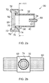
Figure 2a shows a sectional side view of a testing assembly according to an example of the present disclosure andFigure 2b shows a further sectional view corresponding to section A:A as shown inFigure 2a ; -
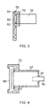
Figure 3 is a side view of a testing assembly according to an alternative example of the present disclosure; and -
Figure 4 is side view of the testing assembly according to the example of the present disclosure receiving a profile measuring device. - With reference to
Figures 2a and 2b , anerosion testing assembly 30 according to an example of the present disclosure, may be adapted to test at least of portion of an abradable surface, liner orcoating 62 of acomponent 60. Theerosion testing assembly 30 may comprise ashroud 32, which may be attachable to thecomponent 60. Theshroud 32 may comprise a first opening 34 and asecond opening 36. The first andsecond openings shroud 32. The shroud may be substantially tubular, e.g. with the first andsecond openings tubular section 40. Theshroud 32 may be circular in cross-section at a first end adjacent to thefirst opening 34 and, as shown inFigure 2b , theshroud 32 may be rectangular, e.g. square, in cross-section at a second end adjacent to the second opening 36. - The
first opening 34 may be adapted, e.g. shaped and/or sized, to receive anerosion gun 50. Theerosion gun 50 may be removable from theshroud 32, e.g. by extraction from thefirst opening 34. Theerosion gun 50 may comprise abarrel 52, which may be located within first opening 34. Thebarrel 52 may correspond in shape and size to thefirst opening 34. Theerosion gun 50 may propel grit and/or air through thebarrel 52 and towards theabradable surface 62 of thecomponent 60. The erosion gun may be connected to a source of grit and a source of compressed air (not shown). - The
shroud 32 may attach or connect to thecomponent 60 such that the second opening 36 of theshroud 32 is adjacent to theabradable surface 62 of thecomponent 60. The grit and/or air may therefore flow from thefirst opening 34, by virtue of theerosion gun 50, through theshroud 32, through the second opening 36 and thence to theabradable surface 62 of thecomponent 60. Theerosion gun 50 may therefore cause erosion of theabradable surface 62, but theshroud 32 may shield other components and/or the remainder of thecomponent 60 from the grit and hence any erosion. Theshroud 32 may comprise a third opening 38. The third opening 38 may be in a side-wall of theshroud 32. Thethird opening 38 may permit the flow of air and/or grit out of theshroud 32, for example once the air and/or grit has hit theabradable surface 62 and fallen to the side-wall of theshroud 32. - The
erosion testing assembly 30 may further comprise aconnector 70 adapted to connect theshroud 32 to thecomponent 60. Theconnector 70 may be part of theshroud 32. Theconnector 70 may act as an interface between the remainder of theshroud 32 and thecomponent 60. Theconnector 70 may be shaped at a first end to receive at least a portion of thecomponent 60 and may be shaped at a second end to connect to the remainder of theshroud 62. Theconnector 70 may convert from the tubular geometry of the remainder of theshroud 32 to the geometry of thecomponent 60. In the example shown, theconnector 70 converts the circular geometry of thetubular section 40 to the rectangular geometry of theconnector 60. - The
connector 70 may comprise alip 72 adapted to hook around thecomponent 60. Accordingly, thelip 72 may secure theconnector 70 and henceerosion testing assembly 30 to thecomponent 60. Thelip 72 may be provided on opposite sides of theconnector 60 and the lip may overhang corresponding sides of thecomponent 60. The connector may be resilient, for example the connector may be made from rubber or any other resilient material. - The
connector 70 may form part of theshroud 32 and may connect to the remainder of theshroud 32. Theconnector 70 may be removably affixed to theshroud 32. One or more connectors may be provided, e.g. to connect to components with different geometries. The connectors may be interchangeable. - The
connector 70 may comprise anabutment surface 76, which may abut thecomponent 60. Theconnector 70 may seal against thecomponent 60. For example, the connector may comprise aseal 74, which may seal against thecomponent 70. Theseal 74 may be provided on theabutment surface 76 of theconnector 70. Theseal 74 may comprise an O-ring and theseal 74 may be made from a resilient material, e.g. rubber. - With reference to
Figure 3 , theconnector 70, in an alternative example, may comprise one ormore protrusions 78. Theprotrusions 78 may be adapted to be received in corresponding recesses 64 in or adjacent to thecomponent 60. Theprotrusions 78 may engage the recesses 64 so as to secure the erosion testing assembly to thecomponent 60. Theprotrusions 78 may be shaped and sized to fit and/or engage the recesses 64. - With reference to
Figure 4 , theerosion gun 50 may be replaced with aprofile measuring device 80. Thefirst opening 34 may also be adapted, e.g. shaped and/or sized, to receive theprofile measuring device 80. Alternatively, theerosion gun 50 orprofile measuring device 80 may fit in thefirst opening 34 by virtue of an intermediate spacer (not shown) to adapt the shape and size of theerosion gun 50 or profile measuring device to thefirst opening 34. Theprofile measuring device 80 may comprise a laser profile measuring device. - The
component 60 may be part of a device. For example, the component may be part of a turbomachine and/or a gas turbine. Theshroud 32, e.g. via theconnector 70, may be attachable to at least a portion of the component in situ within the device. For example, theerosion testing assembly 30 may attach directly to an engine component, e.g. by clipping onto the front and/or rear of a single High Pressure compressor stage (as shown inFigure 2 ) or into the shroud grooves of an Intermediate Pressure compressor drum assembly (as shown inFigure 3 ). However, theerosion testing assembly 30 may be applied to any component with an erosion resistant surface. The erosion testing assembly may also be applied to any component for which the remaining erosion life would be of interest. Such components may include compressor and fan blades with erosion resistant surfaces. - The
connector 70 may be configured to fit a specific component to ensure a good seal and accurate aligning of the erosion test area on theabradable surface 62. Theerosion testing assembly 30 may attach to thecomponent 60 in such a manner that the erosion grit is focused in a direction towards theabradable surface 62. Furthermore, the area outside of a test region on thecomponent 70 may be shielded by theshroud 32 and the seal between theconnector 70 and thecomponent 60. The size of the test region may therefore be limited and damage to the remainder of the component and device may be prevented. - The
profile measurement device 80 may measure the degree of erosion damage to theabradable surface 62. For example, theprofile measurement device 80 may measure the erosion damage after the component has been used in its intended application for a period of time. Theprofile measurement device 80 may measure the profile of theabradable surface 62 prior to erosion testing. Theerosion gun 50 may then replace theprofile measurement device 80 and the erosion test may be undertaken. Theprofile measurement device 80 may then be reattached to measure the extent of further erosion. Alternatively, the pre and post test profile may be measured with a 3D profiler, e.g. an optical 3D profiler, and/or the profile may be compared with a standard replica. Furthermore, a calibration standard may be fixed directly in front of theabradable lining 62 to calibrate theerosion testing assembly 30. The calibration standard may comprise a PMMA (Perspex®) blank. - The erosion testing assembly of the present disclosure may be used on a relatively small area of the component, for example to avoid unduly affecting the performance of the remainder of the component. The abradable surface may be reapplied to the tested area. Different areas of the component may be tested on subsequent tests. The performance of the abradable surface may be monitored and compared against known benchmarks for the abradable surface.
Claims (17)
- An erosion testing assembly (30) adapted to test a surface of a component (60), the testing assembly comprising:a shroud (32) attachable to the component; the shroud being adapted to receive an erosion gun (50).
- The erosion testing assembly of claim 1, wherein the component is part of a device and the shroud is attachable to the component in situ within the device.
- The erosion testing assembly of claim 1 or 2, wherein the erosion testing assembly further comprises a connector (70) adapted to connect the shroud to the component.
- The erosion testing assembly of claim 3, wherein the connector is resilient.
- The erosion testing assembly of any of the preceding claims, wherein the connector comprises a lip (72) for hooking onto the component.
- The erosion testing assembly of any of the preceding claims, wherein the connector comprises protrusions (78) adapted to be received in corresponding recesses (64) in or adjacent to the component.
- The erosion testing assembly of any of the preceding claims, wherein the shroud comprises an opening (34) adapted to receive the erosion gun.
- The erosion testing assembly of any of the preceding claims, wherein the shroud is further adapted to receive a profile measuring device (80).
- The erosion testing assembly of claim 7 or claim 8, wherein the opening is adapted to receive the profile measuring device.
- The erosion testing assembly of any of the preceding claims, wherein the component is part of a turbomachine and/or a gas turbine.
- A method of testing a surface of a component (60), wherein the method comprises:attaching a shroud (32) to the component;connecting an erosion gun (50) to the shroud; andtesting the surface with the erosion gun.
- The method of claim 11, wherein the method further comprises:using the component; andtesting a portion of the surface after use of the component.
- The method of claim 11 or 12, wherein the method further comprises:measuring the surface profile of the surface.
- The method of any of claims 11 to 13, wherein the method further comprises:replacing the erosion gun with a profile measuring device (80).
- A method of testing a surface of a component, wherein the method comprises:using the component; andtesting a portion of the surface with an erosion gun after use of the component.
- An erosion testing assembly, substantially as described herein, with reference to and as shown in the accompanying drawings.
- A method of testing a surface substantially as described herein.
Applications Claiming Priority (1)
| Application Number | Priority Date | Filing Date | Title |
|---|---|---|---|
| GB1101746.4A GB2487742B (en) | 2011-02-02 | 2011-02-02 | An erosion testing assembly |
Publications (3)
| Publication Number | Publication Date |
|---|---|
| EP2485037A2 true EP2485037A2 (en) | 2012-08-08 |
| EP2485037A3 EP2485037A3 (en) | 2012-12-26 |
| EP2485037B1 EP2485037B1 (en) | 2015-05-27 |
Family
ID=43824955
Family Applications (1)
| Application Number | Title | Priority Date | Filing Date |
|---|---|---|---|
| EP12152252.8A Not-in-force EP2485037B1 (en) | 2011-02-02 | 2012-01-24 | An erosion testing assembly |
Country Status (4)
| Country | Link |
|---|---|
| US (1) | US9010178B2 (en) |
| EP (1) | EP2485037B1 (en) |
| GB (1) | GB2487742B (en) |
| SG (1) | SG182942A1 (en) |
Cited By (4)
| Publication number | Priority date | Publication date | Assignee | Title |
|---|---|---|---|---|
| CN104897500A (en) * | 2015-06-19 | 2015-09-09 | 芜湖精塑实业有限公司 | Shakeout testing machine |
| CN111257030A (en) * | 2020-03-30 | 2020-06-09 | 武汉大学 | Hydraulic mechanical hydraulic performance and wear performance experimental device under sand-containing condition |
| US10782280B2 (en) | 2016-04-25 | 2020-09-22 | Pratt & Whitney Canada Corp. | Method and system for evaluation of engine condition |
| CN112525745A (en) * | 2020-11-03 | 2021-03-19 | 北京科技大学 | Physical simulation test device for scouring erosion of tundish lining refractory and using method |
Families Citing this family (8)
| Publication number | Priority date | Publication date | Assignee | Title |
|---|---|---|---|---|
| CN103543077B (en) * | 2013-10-24 | 2016-02-03 | 北京科技大学 | A kind of injecting type erosion corrosion test device |
| CN104634681B (en) * | 2014-12-25 | 2017-08-11 | 江南大学 | A kind of adjustable conical surface pressure water jet cavitation test device in gap |
| US10330664B2 (en) | 2015-06-18 | 2019-06-25 | Pratt & Whitney Canada Corp. | Evaluation of component condition through analysis of material interaction |
| EP3115764A1 (en) * | 2015-07-10 | 2017-01-11 | Siemens Aktiengesellschaft | Test device for hyperbaric testing of a part of a subsea device and method |
| US10519800B2 (en) | 2015-12-08 | 2019-12-31 | Pratt & Whitney Canada Corp. | Method and system for diagnosing a condition of an engine using lubricating fluid analysis |
| CN108344651B (en) * | 2018-01-17 | 2020-06-16 | 中国石油大学(华东) | Experimental device and method for evaluating the erosion resistance of screen tubes |
| US20230226541A1 (en) * | 2022-01-18 | 2023-07-20 | Hollister Incorporated | Fluid absorption test tube |
| CN118583697B (en) * | 2024-07-31 | 2024-11-15 | 永康市法米古厨家居有限责任公司 | A device and method for detecting wear of heating surface of cookware |
Family Cites Families (38)
| Publication number | Priority date | Publication date | Assignee | Title |
|---|---|---|---|---|
| US2628456A (en) * | 1952-01-15 | 1953-02-17 | Mariblast Corp | Sandblasting device |
| US2723498A (en) * | 1953-04-09 | 1955-11-15 | Hastrup Herman | Abrasive blasting machine |
| US2907200A (en) * | 1956-02-14 | 1959-10-06 | Aaron G Roberts | Apparatus for measuring abrasion resistance |
| US3229498A (en) * | 1965-02-16 | 1966-01-18 | Clemtex Ltd | Abrasive tester |
| US3479857A (en) * | 1965-07-20 | 1969-11-25 | Daniel Edgar Bloxsom Jr | Micrometeorite shower creating apparatus and method |
| US3566670A (en) * | 1967-06-26 | 1971-03-02 | Aerotherm Corp | Reentry vehicle heat shield testing apparatus and method |
| US3709026A (en) * | 1968-11-12 | 1973-01-09 | Kms Ind Inc | Apparatus and method for simulating spacecraft erosion |
| US3813126A (en) * | 1972-10-02 | 1974-05-28 | Bendix Corp | Continuously operable underground mining vehicle |
| US3978761A (en) * | 1975-06-26 | 1976-09-07 | Thomas & Betts Corporation | Fastener assembly |
| US4045915A (en) * | 1975-10-06 | 1977-09-06 | Enviro-Blast International | Portable sandblaster |
| US4375740A (en) * | 1978-05-25 | 1983-03-08 | Jpd Manufacturing Limited | Portable abrading cabinet device for recycling abrasive blasting system |
| US4395850A (en) * | 1978-05-25 | 1983-08-02 | Jpd Manufacturing Limited | Adapter device for tools of an abrasive blasting system |
| US4232487A (en) * | 1978-05-25 | 1980-11-11 | Knox Manufacturing Co. | Abrading device |
| US4212138A (en) * | 1978-09-05 | 1980-07-15 | Gary Hutchison | Portable confined surface sand blast apparatus |
| US4418730A (en) * | 1980-10-16 | 1983-12-06 | Dover Corporation | Automatic shut-off nozzle with vapor return seal |
| SU1019286A1 (en) * | 1982-01-06 | 1983-05-23 | Московский Ордена Трудового Красного Знамени Институт Химического Машиностроения | Device for investigating structure materials under gas-abrasive wear |
| DE3478202D1 (en) * | 1983-01-06 | 1989-06-22 | Nat Res Dev | Electrostatic spray head |
| IT1198660B (en) | 1983-08-02 | 1988-12-21 | Ottica Ist Naz | MULTIFOCAL OPTICAL PROFILOMETER FOR DISPERSION |
| US4716849A (en) * | 1985-05-31 | 1988-01-05 | Tracor Hydronautics, Inc. | Erosive-jet diver tool |
| US5010693A (en) * | 1989-09-15 | 1991-04-30 | Hatch Tobie D | Self-contained sandblasting unit |
| US5069260A (en) * | 1991-01-28 | 1991-12-03 | Shea Reeford P | Fuel dispensing nozzle with vapor-proof seal |
| JP2964654B2 (en) * | 1991-01-30 | 1999-10-18 | 住友電気工業株式会社 | Wear evaluation test method |
| US5526680A (en) * | 1994-07-27 | 1996-06-18 | H. B. Fuller Automotive Technology Systems, Inc. | Hydraulic press flow viscometer |
| JPH0862114A (en) * | 1994-08-25 | 1996-03-08 | Ishikawajima Harima Heavy Ind Co Ltd | High temperature blast erosion test equipment |
| US5531634A (en) * | 1995-02-03 | 1996-07-02 | Schott; Paul | Method of using an abrasive material for blast cleaning of solid surfaces |
| DE19747838C2 (en) | 1997-10-19 | 2001-07-12 | Gp Granulate Pneumatic Geraete | Method and device for the dry removal of coatings, graffiti or other surface contaminants |
| US5998242A (en) * | 1997-10-27 | 1999-12-07 | Lsi Logic Corporation | Vacuum assisted underfill process and apparatus for semiconductor package fabrication |
| JP2000171371A (en) * | 1998-04-08 | 2000-06-23 | Makoo Kk | Abrasion tester and abrasion test method |
| US6192763B1 (en) * | 1998-06-22 | 2001-02-27 | Frederick D. Cartwright | Method and apparatus for determining the strength path of a mortar or concrete mix |
| US7959983B1 (en) * | 2003-10-21 | 2011-06-14 | Farrar Lawrence C | Thermal spray formation of polymer compositions |
| US7127958B2 (en) * | 2004-04-21 | 2006-10-31 | General Motors Corporation | Dust testing facility for motor vehicles |
| US7988376B2 (en) * | 2005-12-12 | 2011-08-02 | Thistledown Farms Llc | Fluid applicators and methods of making same |
| US7347768B1 (en) * | 2006-07-28 | 2008-03-25 | United States Of America As Represented By The Secretary Of The Army | Apparatus and method to test abrasion resistance of material using airborne particulate |
| CN201314887Y (en) * | 2008-12-18 | 2009-09-23 | 刘少光 | Pressurized sectional heating high temperature erosion and abrasion tester |
| US8047048B2 (en) * | 2009-02-03 | 2011-11-01 | Robert J. Jenkins & Company | Test device for refractory material |
| US8113037B2 (en) * | 2009-03-30 | 2012-02-14 | General Electric Company | Method for testing high temperature mechanical durability of articles |
| CN201716245U (en) * | 2010-06-13 | 2011-01-19 | 河海大学常州校区 | Test piece surface erosion wear testing device |
| US8510874B2 (en) * | 2010-07-02 | 2013-08-20 | Carol Duboc | Toilet plunger cleaning system |
-
2011
- 2011-02-02 GB GB1101746.4A patent/GB2487742B/en not_active Expired - Fee Related
-
2012
- 2012-01-24 US US13/357,028 patent/US9010178B2/en not_active Expired - Fee Related
- 2012-01-24 EP EP12152252.8A patent/EP2485037B1/en not_active Not-in-force
- 2012-01-27 SG SG2012006151A patent/SG182942A1/en unknown
Non-Patent Citations (1)
| Title |
|---|
| None |
Cited By (4)
| Publication number | Priority date | Publication date | Assignee | Title |
|---|---|---|---|---|
| CN104897500A (en) * | 2015-06-19 | 2015-09-09 | 芜湖精塑实业有限公司 | Shakeout testing machine |
| US10782280B2 (en) | 2016-04-25 | 2020-09-22 | Pratt & Whitney Canada Corp. | Method and system for evaluation of engine condition |
| CN111257030A (en) * | 2020-03-30 | 2020-06-09 | 武汉大学 | Hydraulic mechanical hydraulic performance and wear performance experimental device under sand-containing condition |
| CN112525745A (en) * | 2020-11-03 | 2021-03-19 | 北京科技大学 | Physical simulation test device for scouring erosion of tundish lining refractory and using method |
Also Published As
| Publication number | Publication date |
|---|---|
| US9010178B2 (en) | 2015-04-21 |
| EP2485037A3 (en) | 2012-12-26 |
| GB2487742A (en) | 2012-08-08 |
| EP2485037B1 (en) | 2015-05-27 |
| SG182942A1 (en) | 2012-08-30 |
| GB201101746D0 (en) | 2011-03-16 |
| US20120192629A1 (en) | 2012-08-02 |
| GB2487742B (en) | 2013-08-21 |
Similar Documents
| Publication | Publication Date | Title |
|---|---|---|
| EP2485037B1 (en) | An erosion testing assembly | |
| EP2679778B1 (en) | A method for measuring geometry deformations of a turbine component | |
| US7925454B1 (en) | Process for determining a remaining life of a deteriorated turbine component | |
| US9752873B2 (en) | Tool for measuring geometrical parameters of a blade or vane in a turbomachine | |
| Fois et al. | Adhesive transfer in aero-engine abradable linings contact | |
| EP2078953A3 (en) | System and method for detecting and analyzing compositions | |
| JP2014530320A (en) | Centrifugal compressor provided with a marker for measuring wear, and method for monitoring wear using said marker | |
| US20090084170A1 (en) | Systems and Methods for Performing Cooling Airflow Analysis of Gas Turbine Engine Components | |
| GB2462829A (en) | Clearance measurement method | |
| EP3168591A1 (en) | Systems and methods for monitoring components | |
| WO2010036476A1 (en) | Measuring intensity of shot peening in areas with difficult accessibility | |
| US20160069829A1 (en) | Hardware and method for implementation of in situ acoustic thermograph inspections | |
| EP3623788B1 (en) | Automated distress ranking system | |
| US8297136B2 (en) | Instrumentation arrangement | |
| JP6021790B2 (en) | Turbine rotor inspection method | |
| CA1233320A (en) | Method of removing a coating | |
| JP4688479B2 (en) | Method and apparatus for evaluating rotating machinery | |
| US20250198735A1 (en) | Method for locating a mark on a turbomachine casing | |
| CN106768033A (en) | A kind of method of measurement ion thruster inside deposition sputtering | |
| Versluis et al. | Brush Seal Wear Measurements for High-Speed, High-Temperature, Low-Pressure-Turbine Applications | |
| JP2003294716A (en) | Turbine inspection method | |
| US11105220B2 (en) | Turbine element cleaning process | |
| CN121347354A (en) | A corrosion damage analysis method for the entire aero-engine | |
| EP2039883A2 (en) | Methods for repairing gas turbine engine components | |
| RU2618602C1 (en) | Method for x-ray control parts of gas turbine engine |
Legal Events
| Date | Code | Title | Description |
|---|---|---|---|
| PUAI | Public reference made under article 153(3) epc to a published international application that has entered the european phase |
Free format text: ORIGINAL CODE: 0009012 |
|
| AK | Designated contracting states |
Kind code of ref document: A2 Designated state(s): AL AT BE BG CH CY CZ DE DK EE ES FI FR GB GR HR HU IE IS IT LI LT LU LV MC MK MT NL NO PL PT RO RS SE SI SK SM TR |
|
| AX | Request for extension of the european patent |
Extension state: BA ME |
|
| PUAL | Search report despatched |
Free format text: ORIGINAL CODE: 0009013 |
|
| AK | Designated contracting states |
Kind code of ref document: A3 Designated state(s): AL AT BE BG CH CY CZ DE DK EE ES FI FR GB GR HR HU IE IS IT LI LT LU LV MC MK MT NL NO PL PT RO RS SE SI SK SM TR |
|
| AX | Request for extension of the european patent |
Extension state: BA ME |
|
| RIC1 | Information provided on ipc code assigned before grant |
Ipc: G01N 3/56 20060101AFI20121122BHEP Ipc: D06F 58/10 20060101ALI20121122BHEP Ipc: D06F 57/00 20060101ALI20121122BHEP |
|
| 17P | Request for examination filed |
Effective date: 20130626 |
|
| RBV | Designated contracting states (corrected) |
Designated state(s): AL AT BE BG CH CY CZ DE DK EE ES FI FR GB GR HR HU IE IS IT LI LT LU LV MC MK MT NL NO PL PT RO RS SE SI SK SM TR |
|
| 17Q | First examination report despatched |
Effective date: 20140627 |
|
| GRAP | Despatch of communication of intention to grant a patent |
Free format text: ORIGINAL CODE: EPIDOSNIGR1 |
|
| GRAS | Grant fee paid |
Free format text: ORIGINAL CODE: EPIDOSNIGR3 |
|
| INTG | Intention to grant announced |
Effective date: 20150402 |
|
| GRAA | (expected) grant |
Free format text: ORIGINAL CODE: 0009210 |
|
| AK | Designated contracting states |
Kind code of ref document: B1 Designated state(s): AL AT BE BG CH CY CZ DE DK EE ES FI FR GB GR HR HU IE IS IT LI LT LU LV MC MK MT NL NO PL PT RO RS SE SI SK SM TR |
|
| REG | Reference to a national code |
Ref country code: GB Ref legal event code: FG4D |
|
| REG | Reference to a national code |
Ref country code: CH Ref legal event code: EP |
|
| REG | Reference to a national code |
Ref country code: AT Ref legal event code: REF Ref document number: 729117 Country of ref document: AT Kind code of ref document: T Effective date: 20150615 |
|
| REG | Reference to a national code |
Ref country code: IE Ref legal event code: FG4D |
|
| REG | Reference to a national code |
Ref country code: DE Ref legal event code: R096 Ref document number: 602012007498 Country of ref document: DE |
|
| RAP2 | Party data changed (patent owner data changed or rights of a patent transferred) |
Owner name: ROLLS-ROYCE PLC |
|
| REG | Reference to a national code |
Ref country code: AT Ref legal event code: MK05 Ref document number: 729117 Country of ref document: AT Kind code of ref document: T Effective date: 20150527 |
|
| REG | Reference to a national code |
Ref country code: LT Ref legal event code: MG4D |
|
| PG25 | Lapsed in a contracting state [announced via postgrant information from national office to epo] |
Ref country code: NO Free format text: LAPSE BECAUSE OF FAILURE TO SUBMIT A TRANSLATION OF THE DESCRIPTION OR TO PAY THE FEE WITHIN THE PRESCRIBED TIME-LIMIT Effective date: 20150827 Ref country code: PT Free format text: LAPSE BECAUSE OF FAILURE TO SUBMIT A TRANSLATION OF THE DESCRIPTION OR TO PAY THE FEE WITHIN THE PRESCRIBED TIME-LIMIT Effective date: 20150928 Ref country code: LT Free format text: LAPSE BECAUSE OF FAILURE TO SUBMIT A TRANSLATION OF THE DESCRIPTION OR TO PAY THE FEE WITHIN THE PRESCRIBED TIME-LIMIT Effective date: 20150527 Ref country code: HR Free format text: LAPSE BECAUSE OF FAILURE TO SUBMIT A TRANSLATION OF THE DESCRIPTION OR TO PAY THE FEE WITHIN THE PRESCRIBED TIME-LIMIT Effective date: 20150527 Ref country code: FI Free format text: LAPSE BECAUSE OF FAILURE TO SUBMIT A TRANSLATION OF THE DESCRIPTION OR TO PAY THE FEE WITHIN THE PRESCRIBED TIME-LIMIT Effective date: 20150527 Ref country code: ES Free format text: LAPSE BECAUSE OF FAILURE TO SUBMIT A TRANSLATION OF THE DESCRIPTION OR TO PAY THE FEE WITHIN THE PRESCRIBED TIME-LIMIT Effective date: 20150527 |
|
| REG | Reference to a national code |
Ref country code: NL Ref legal event code: MP Effective date: 20150527 |
|
| PG25 | Lapsed in a contracting state [announced via postgrant information from national office to epo] |
Ref country code: LV Free format text: LAPSE BECAUSE OF FAILURE TO SUBMIT A TRANSLATION OF THE DESCRIPTION OR TO PAY THE FEE WITHIN THE PRESCRIBED TIME-LIMIT Effective date: 20150527 Ref country code: AT Free format text: LAPSE BECAUSE OF FAILURE TO SUBMIT A TRANSLATION OF THE DESCRIPTION OR TO PAY THE FEE WITHIN THE PRESCRIBED TIME-LIMIT Effective date: 20150527 Ref country code: RS Free format text: LAPSE BECAUSE OF FAILURE TO SUBMIT A TRANSLATION OF THE DESCRIPTION OR TO PAY THE FEE WITHIN THE PRESCRIBED TIME-LIMIT Effective date: 20150527 Ref country code: BG Free format text: LAPSE BECAUSE OF FAILURE TO SUBMIT A TRANSLATION OF THE DESCRIPTION OR TO PAY THE FEE WITHIN THE PRESCRIBED TIME-LIMIT Effective date: 20150827 Ref country code: GR Free format text: LAPSE BECAUSE OF FAILURE TO SUBMIT A TRANSLATION OF THE DESCRIPTION OR TO PAY THE FEE WITHIN THE PRESCRIBED TIME-LIMIT Effective date: 20150828 Ref country code: IS Free format text: LAPSE BECAUSE OF FAILURE TO SUBMIT A TRANSLATION OF THE DESCRIPTION OR TO PAY THE FEE WITHIN THE PRESCRIBED TIME-LIMIT Effective date: 20150927 |
|
| REG | Reference to a national code |
Ref country code: FR Ref legal event code: PLFP Year of fee payment: 5 |
|
| PG25 | Lapsed in a contracting state [announced via postgrant information from national office to epo] |
Ref country code: DK Free format text: LAPSE BECAUSE OF FAILURE TO SUBMIT A TRANSLATION OF THE DESCRIPTION OR TO PAY THE FEE WITHIN THE PRESCRIBED TIME-LIMIT Effective date: 20150527 Ref country code: EE Free format text: LAPSE BECAUSE OF FAILURE TO SUBMIT A TRANSLATION OF THE DESCRIPTION OR TO PAY THE FEE WITHIN THE PRESCRIBED TIME-LIMIT Effective date: 20150527 |
|
| PG25 | Lapsed in a contracting state [announced via postgrant information from national office to epo] |
Ref country code: CZ Free format text: LAPSE BECAUSE OF FAILURE TO SUBMIT A TRANSLATION OF THE DESCRIPTION OR TO PAY THE FEE WITHIN THE PRESCRIBED TIME-LIMIT Effective date: 20150527 Ref country code: SK Free format text: LAPSE BECAUSE OF FAILURE TO SUBMIT A TRANSLATION OF THE DESCRIPTION OR TO PAY THE FEE WITHIN THE PRESCRIBED TIME-LIMIT Effective date: 20150527 Ref country code: PL Free format text: LAPSE BECAUSE OF FAILURE TO SUBMIT A TRANSLATION OF THE DESCRIPTION OR TO PAY THE FEE WITHIN THE PRESCRIBED TIME-LIMIT Effective date: 20150527 Ref country code: RO Free format text: LAPSE BECAUSE OF NON-PAYMENT OF DUE FEES Effective date: 20150527 |
|
| REG | Reference to a national code |
Ref country code: DE Ref legal event code: R097 Ref document number: 602012007498 Country of ref document: DE |
|
| PLBE | No opposition filed within time limit |
Free format text: ORIGINAL CODE: 0009261 |
|
| STAA | Information on the status of an ep patent application or granted ep patent |
Free format text: STATUS: NO OPPOSITION FILED WITHIN TIME LIMIT |
|
| PG25 | Lapsed in a contracting state [announced via postgrant information from national office to epo] |
Ref country code: IT Free format text: LAPSE BECAUSE OF FAILURE TO SUBMIT A TRANSLATION OF THE DESCRIPTION OR TO PAY THE FEE WITHIN THE PRESCRIBED TIME-LIMIT Effective date: 20150527 |
|
| 26N | No opposition filed |
Effective date: 20160301 |
|
| REG | Reference to a national code |
Ref country code: DE Ref legal event code: R082 Ref document number: 602012007498 Country of ref document: DE Representative=s name: HERNANDEZ, YORCK, DIPL.-ING., DE |
|
| PG25 | Lapsed in a contracting state [announced via postgrant information from national office to epo] |
Ref country code: SI Free format text: LAPSE BECAUSE OF FAILURE TO SUBMIT A TRANSLATION OF THE DESCRIPTION OR TO PAY THE FEE WITHIN THE PRESCRIBED TIME-LIMIT Effective date: 20150527 Ref country code: BE Free format text: LAPSE BECAUSE OF NON-PAYMENT OF DUE FEES Effective date: 20160131 |
|
| PG25 | Lapsed in a contracting state [announced via postgrant information from national office to epo] |
Ref country code: BE Free format text: LAPSE BECAUSE OF FAILURE TO SUBMIT A TRANSLATION OF THE DESCRIPTION OR TO PAY THE FEE WITHIN THE PRESCRIBED TIME-LIMIT Effective date: 20150527 Ref country code: LU Free format text: LAPSE BECAUSE OF FAILURE TO SUBMIT A TRANSLATION OF THE DESCRIPTION OR TO PAY THE FEE WITHIN THE PRESCRIBED TIME-LIMIT Effective date: 20160124 |
|
| REG | Reference to a national code |
Ref country code: CH Ref legal event code: PL |
|
| PG25 | Lapsed in a contracting state [announced via postgrant information from national office to epo] |
Ref country code: MC Free format text: LAPSE BECAUSE OF FAILURE TO SUBMIT A TRANSLATION OF THE DESCRIPTION OR TO PAY THE FEE WITHIN THE PRESCRIBED TIME-LIMIT Effective date: 20150527 |
|
| PG25 | Lapsed in a contracting state [announced via postgrant information from national office to epo] |
Ref country code: CH Free format text: LAPSE BECAUSE OF NON-PAYMENT OF DUE FEES Effective date: 20160131 Ref country code: LI Free format text: LAPSE BECAUSE OF NON-PAYMENT OF DUE FEES Effective date: 20160131 |
|
| REG | Reference to a national code |
Ref country code: IE Ref legal event code: MM4A |
|
| REG | Reference to a national code |
Ref country code: FR Ref legal event code: PLFP Year of fee payment: 6 |
|
| PG25 | Lapsed in a contracting state [announced via postgrant information from national office to epo] |
Ref country code: IE Free format text: LAPSE BECAUSE OF NON-PAYMENT OF DUE FEES Effective date: 20160124 |
|
| PG25 | Lapsed in a contracting state [announced via postgrant information from national office to epo] |
Ref country code: SE Free format text: LAPSE BECAUSE OF FAILURE TO SUBMIT A TRANSLATION OF THE DESCRIPTION OR TO PAY THE FEE WITHIN THE PRESCRIBED TIME-LIMIT Effective date: 20150527 Ref country code: NL Free format text: LAPSE BECAUSE OF FAILURE TO SUBMIT A TRANSLATION OF THE DESCRIPTION OR TO PAY THE FEE WITHIN THE PRESCRIBED TIME-LIMIT Effective date: 20150527 |
|
| PG25 | Lapsed in a contracting state [announced via postgrant information from national office to epo] |
Ref country code: MT Free format text: LAPSE BECAUSE OF FAILURE TO SUBMIT A TRANSLATION OF THE DESCRIPTION OR TO PAY THE FEE WITHIN THE PRESCRIBED TIME-LIMIT Effective date: 20150527 |
|
| REG | Reference to a national code |
Ref country code: FR Ref legal event code: PLFP Year of fee payment: 7 |
|
| PG25 | Lapsed in a contracting state [announced via postgrant information from national office to epo] |
Ref country code: SM Free format text: LAPSE BECAUSE OF FAILURE TO SUBMIT A TRANSLATION OF THE DESCRIPTION OR TO PAY THE FEE WITHIN THE PRESCRIBED TIME-LIMIT Effective date: 20150527 Ref country code: HU Free format text: LAPSE BECAUSE OF FAILURE TO SUBMIT A TRANSLATION OF THE DESCRIPTION OR TO PAY THE FEE WITHIN THE PRESCRIBED TIME-LIMIT; INVALID AB INITIO Effective date: 20120124 Ref country code: CY Free format text: LAPSE BECAUSE OF FAILURE TO SUBMIT A TRANSLATION OF THE DESCRIPTION OR TO PAY THE FEE WITHIN THE PRESCRIBED TIME-LIMIT Effective date: 20150527 |
|
| PG25 | Lapsed in a contracting state [announced via postgrant information from national office to epo] |
Ref country code: MT Free format text: LAPSE BECAUSE OF FAILURE TO SUBMIT A TRANSLATION OF THE DESCRIPTION OR TO PAY THE FEE WITHIN THE PRESCRIBED TIME-LIMIT Effective date: 20160131 Ref country code: MK Free format text: LAPSE BECAUSE OF FAILURE TO SUBMIT A TRANSLATION OF THE DESCRIPTION OR TO PAY THE FEE WITHIN THE PRESCRIBED TIME-LIMIT Effective date: 20150527 Ref country code: TR Free format text: LAPSE BECAUSE OF FAILURE TO SUBMIT A TRANSLATION OF THE DESCRIPTION OR TO PAY THE FEE WITHIN THE PRESCRIBED TIME-LIMIT Effective date: 20150527 |
|
| PG25 | Lapsed in a contracting state [announced via postgrant information from national office to epo] |
Ref country code: AL Free format text: LAPSE BECAUSE OF FAILURE TO SUBMIT A TRANSLATION OF THE DESCRIPTION OR TO PAY THE FEE WITHIN THE PRESCRIBED TIME-LIMIT Effective date: 20150527 |
|
| PGFP | Annual fee paid to national office [announced via postgrant information from national office to epo] |
Ref country code: GB Payment date: 20200127 Year of fee payment: 9 Ref country code: DE Payment date: 20200129 Year of fee payment: 9 |
|
| PGFP | Annual fee paid to national office [announced via postgrant information from national office to epo] |
Ref country code: FR Payment date: 20200127 Year of fee payment: 9 |
|
| REG | Reference to a national code |
Ref country code: DE Ref legal event code: R119 Ref document number: 602012007498 Country of ref document: DE |
|
| GBPC | Gb: european patent ceased through non-payment of renewal fee |
Effective date: 20210124 |
|
| PG25 | Lapsed in a contracting state [announced via postgrant information from national office to epo] |
Ref country code: FR Free format text: LAPSE BECAUSE OF NON-PAYMENT OF DUE FEES Effective date: 20210131 |
|
| PG25 | Lapsed in a contracting state [announced via postgrant information from national office to epo] |
Ref country code: DE Free format text: LAPSE BECAUSE OF NON-PAYMENT OF DUE FEES Effective date: 20210803 Ref country code: GB Free format text: LAPSE BECAUSE OF NON-PAYMENT OF DUE FEES Effective date: 20210124 |