EP2485011B1 - Arrangement to measure the deflection of an object - Google Patents
Arrangement to measure the deflection of an object Download PDFInfo
- Publication number
- EP2485011B1 EP2485011B1 EP20110153559 EP11153559A EP2485011B1 EP 2485011 B1 EP2485011 B1 EP 2485011B1 EP 20110153559 EP20110153559 EP 20110153559 EP 11153559 A EP11153559 A EP 11153559A EP 2485011 B1 EP2485011 B1 EP 2485011B1
- Authority
- EP
- European Patent Office
- Prior art keywords
- antenna
- reflector
- blade
- wind turbine
- radio signal
- Prior art date
- Legal status (The legal status is an assumption and is not a legal conclusion. Google has not performed a legal analysis and makes no representation as to the accuracy of the status listed.)
- Not-in-force
Links
Images

Classifications
-
- G—PHYSICS
- G01—MEASURING; TESTING
- G01B—MEASURING LENGTH, THICKNESS OR SIMILAR LINEAR DIMENSIONS; MEASURING ANGLES; MEASURING AREAS; MEASURING IRREGULARITIES OF SURFACES OR CONTOURS
- G01B15/00—Measuring arrangements characterised by the use of electromagnetic waves or particle radiation, e.g. by the use of microwaves, X-rays, gamma rays or electrons
- G01B15/06—Measuring arrangements characterised by the use of electromagnetic waves or particle radiation, e.g. by the use of microwaves, X-rays, gamma rays or electrons for measuring the deformation in a solid
-
- G—PHYSICS
- G01—MEASURING; TESTING
- G01S—RADIO DIRECTION-FINDING; RADIO NAVIGATION; DETERMINING DISTANCE OR VELOCITY BY USE OF RADIO WAVES; LOCATING OR PRESENCE-DETECTING BY USE OF THE REFLECTION OR RERADIATION OF RADIO WAVES; ANALOGOUS ARRANGEMENTS USING OTHER WAVES
- G01S13/00—Systems using the reflection or reradiation of radio waves, e.g. radar systems; Analogous systems using reflection or reradiation of waves whose nature or wavelength is irrelevant or unspecified
- G01S13/02—Systems using reflection of radio waves, e.g. primary radar systems; Analogous systems
- G01S13/06—Systems determining position data of a target
- G01S13/42—Simultaneous measurement of distance and other co-ordinates
-
- G—PHYSICS
- G01—MEASURING; TESTING
- G01S—RADIO DIRECTION-FINDING; RADIO NAVIGATION; DETERMINING DISTANCE OR VELOCITY BY USE OF RADIO WAVES; LOCATING OR PRESENCE-DETECTING BY USE OF THE REFLECTION OR RERADIATION OF RADIO WAVES; ANALOGOUS ARRANGEMENTS USING OTHER WAVES
- G01S3/00—Direction-finders for determining the direction from which infrasonic, sonic, ultrasonic or electromagnetic waves, or particle emission, not having a directional significance, are being received
- G01S3/02—Direction-finders for determining the direction from which infrasonic, sonic, ultrasonic or electromagnetic waves, or particle emission, not having a directional significance, are being received using radio waves
- G01S3/14—Systems for determining direction or deviation from predetermined direction
- G01S3/46—Systems for determining direction or deviation from predetermined direction using antennas spaced apart and measuring phase or time difference between signals therefrom, i.e. path-difference systems
- G01S3/48—Systems for determining direction or deviation from predetermined direction using antennas spaced apart and measuring phase or time difference between signals therefrom, i.e. path-difference systems the waves arriving at the antennas being continuous or intermittent and the phase difference of signals derived therefrom being measured
-
- G—PHYSICS
- G01—MEASURING; TESTING
- G01S—RADIO DIRECTION-FINDING; RADIO NAVIGATION; DETERMINING DISTANCE OR VELOCITY BY USE OF RADIO WAVES; LOCATING OR PRESENCE-DETECTING BY USE OF THE REFLECTION OR RERADIATION OF RADIO WAVES; ANALOGOUS ARRANGEMENTS USING OTHER WAVES
- G01S13/00—Systems using the reflection or reradiation of radio waves, e.g. radar systems; Analogous systems using reflection or reradiation of waves whose nature or wavelength is irrelevant or unspecified
- G01S13/74—Systems using reradiation of radio waves, e.g. secondary radar systems; Analogous systems
- G01S13/75—Systems using reradiation of radio waves, e.g. secondary radar systems; Analogous systems using transponders powered from received waves, e.g. using passive transponders, or using passive reflectors
-
- G—PHYSICS
- G01—MEASURING; TESTING
- G01S—RADIO DIRECTION-FINDING; RADIO NAVIGATION; DETERMINING DISTANCE OR VELOCITY BY USE OF RADIO WAVES; LOCATING OR PRESENCE-DETECTING BY USE OF THE REFLECTION OR RERADIATION OF RADIO WAVES; ANALOGOUS ARRANGEMENTS USING OTHER WAVES
- G01S13/00—Systems using the reflection or reradiation of radio waves, e.g. radar systems; Analogous systems using reflection or reradiation of waves whose nature or wavelength is irrelevant or unspecified
- G01S13/88—Radar or analogous systems specially adapted for specific applications
Definitions
- the invention relates to an arrangement to measure the deflection or bending of an object, preferably to measure the deflection or bending of a wind-turbine blade.
- Blades of modern wind turbines are quite long - they are up to 45 meters long or even more. Thus their shape and their characteristics need to be optimized, especially to prevent that turning blades hit the tower while the wind turbine is in operation.
- strain gauges on the blade-surface. They are mainly used for test purposes to gather a certain knowledge about the blade when it is stressed.
- gauges are expensive, especially asides a wind turbine which is in operation.
- the equipment (especially the cabling) is exposed to lightning strikes, thus the gauges are mainly used for time-limited test purposes.
- Document DE 10 2006 054 667 A1 describes a warning system.
- the system is used to prevent that turning rotor-blades of a wind turbine hit the wind turbine tower.
- the bending of a turning blade is determined by sensors.
- the sensors perform optical measurements, ultra-sonic-measurements or RADAR-based measurements to determine the bending of the blade.
- the blade-deflection can be measured while the wind turbine is in operational mode. All relevant components are a well integrated part of the wind turbine, thus the arrangement is "long-time fully functional".
- the antenna system is part of an active radar system.
- the radar system contains a radar transmitter and a radar receiver, being used to send and receive a radar signal as radio signal.
- the radar transmitter is connected with the transmit antenna, while the radar receiver is connected with the receive antenna.
- a passive reflector is arranged at the tip-end of a wind turbine blade, while the tip-end is the first end of the object. Thus the tip end defines the first position.
- the blade is connected via its root-end, which is the second end of the object, with a hub.
- the antenna system is arranged at the root end of the blade, thus the root end of the blade defines the second position.
- the blade is connected via its root-end, which is the second end of the object, with the hub of the wind turbine while the hub is connected with a nacelle of the wind turbine.
- the antenna system is arranged at the nacelle, thus the nacelle defines the second position.
- the receive antenna contains a number of single antennas, which are be arranged as a linear antenna array.
- each single antenna receives the radio signal with a certain phase-difference, which is assigned to the position of the certain single antenna.
- the evaluation unit is arranged and prepared to measure these phase-differences and to calculate the deflection based on the phase-differences.
- the reflector and the antenna-system are coupled by a number of radio signals.
- the measurement is enhanced and the results are more exact.
- each blade of the wind turbine contains a passive reflector.
- the measurement is done at the wind turbine, which is in operation, and the results are more exact in view to each blade.
- the receive antenna is a directional antenna to maximize the signal strength of the radio signal via its antenna-gain.
- the transmit antenna might be a directional antenna to maximize the signal strength of the radio signal via its antenna-gain.
- the reflector might be prepared and shaped to amplify the radio signal.
- the reflector is a corner-reflector or a semi-passive reflector.
- the semi-passive reflector may be operated at low power by help of a battery.
- the semi-passive reflector may be even used to modulate the reflected radio signal.
- the signal sensitivity is improved. Even interfering reflections of the radio signal, caused by the environment, are reduced.
- the reflector is prepared to modulate the reflected radio signal.
- the results are more exact.
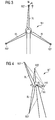
- FIG 1 shows one preferred arrangement according to the invention.
- the deflection DEF or bending of a wind turbine blade BL needs to be measured.
- a reflector REF is arranged asides a first end of the blade BL.
- An antenna-system LAA contains at least one transmit antenna TA and - as shown in this example - four receive antennas RA.
- the antenna system LAA is arranged asides the nacelle of the wind turbine and close to the second end of the blade BL.
- the antenna system LAA is part of an active radar system.
- the four receive antennas RA are arranged as "linear antenna array”.
- the reflector REF and the antenna-system LAA are coupled by a radio signal RS, which is sent from the transmit antenna TA via the reflector REF towards the receive antennas RA.
- the receive antennas RA are connected with an evaluation unit EU, which is prepared to measure the deflection DEF between the first end of the blade BL and the second end of the blade BL based on the received radio signal RS.
- the blade BL rotates around a longitudinal axis AX of the nacelle and is bended or deflected due to the wind load for example.
- the deflection DEF of the blade BL is measured while the wind turbine is in operation / is at work.
- the blade BL is "turned out of the wind” if the deflection exceeds a certain limit. This action might be done by help the pitch-system of the blade BL or by help of the yawing-system of the nacelle if needed (not shown here in detail).
- FIG 2 shows measured phase differences ⁇ in view to the arrangement of FIG 1 .
- receive antennas RA1, RA2, RA3 and RA4 are arranged in a line as linear antenna array.
- the radio signal RS is reflected by the reflector REF, thus the reflected radio signal RS is received by the four receive antennas RA1 up to RA4.
- Each of the single antennas RA1 to RA4 receive the radio signal RS with a certain phase-difference ⁇ , while the phase difference ⁇ is assigned to the position of the certain single antenna RA1 to RA4.
- the evaluation unit EU as shown in FIG 1 is arranged and prepared to measure these phase-differences ⁇ and to calculate the deflection DEF based on the phase-differences ⁇ .
- phase-differences ⁇ can be also written as angle ⁇ which is a certain value of the deflection DEF of the blade BL.
- the certain phase-difference ⁇ is close related to the deflection DEF of the blade BL.
- the value of the phase-difference ⁇ increases if the deflection DEF increases.
- FIG 3 shows an improved arrangement in view to the figures FIG 1 and FIG 2 .
- Each blade BL of the wind turbine WT is equipped with a dedicated reflector REF.
- FIG 4 shows an arrangement which is not part of the invention.
- This antenna system LAA is arranged with the other parts of the active radar system behind the rotor and is connected with the nacelle NA of the wind turbine WT.
Landscapes
- Engineering & Computer Science (AREA)
- Radar, Positioning & Navigation (AREA)
- Remote Sensing (AREA)
- Physics & Mathematics (AREA)
- General Physics & Mathematics (AREA)
- Computer Networks & Wireless Communication (AREA)
- Electromagnetism (AREA)
- Wind Motors (AREA)
- Variable-Direction Aerials And Aerial Arrays (AREA)
- Aerials With Secondary Devices (AREA)
Description
- The invention relates to an arrangement to measure the deflection or bending of an object, preferably to measure the deflection or bending of a wind-turbine blade.
- Blades of modern wind turbines are quite long - they are up to 45 meters long or even more. Thus their shape and their characteristics need to be optimized, especially to prevent that turning blades hit the tower while the wind turbine is in operation.
- Especially the deflection or bending of the blade near its tip-end needs to be known to prevent those damages.
- It is known to attach strain gauges on the blade-surface. They are mainly used for test purposes to gather a certain knowledge about the blade when it is stressed.
- The installation of gauges and the installation of their electrical cabling needed is expensive, especially asides a wind turbine which is in operation. The equipment (especially the cabling) is exposed to lightning strikes, thus the gauges are mainly used for time-limited test purposes.
- It is known to use distance-measurement-systems to measure blade-deflections. Parts of the system (like a reflector for wireless transmitted optical signals) are arranged inside a cavity of the blade, while other parts of the system (like an optical transmitter and/or optical receiver) are arranged inside the hub of the wind turbine.
- Only a certain blade-deflection can be measured by theses systems due to the location of the system-parts. The deflection of the tip-end of the blade can only be approximated as the cavity is not elongated towards the tip-end of the blade.
- Document
DE 10 2006 054 667 A1 describes a warning system. The system is used to prevent that turning rotor-blades of a wind turbine hit the wind turbine tower. The bending of a turning blade is determined by sensors. The sensors perform optical measurements, ultra-sonic-measurements or RADAR-based measurements to determine the bending of the blade. - It is therefore the aim of the invention to provide an improved arrangement and method to measure the deflection or bending of an extended object, especially for a wind-turbine-blade.
- This aim is reached by an arrangement having the features according to claim 1.
- Preferred embodiments of the invention are object of the dependent claims.
- Due to the arrangement according to the invention there is no need for an additional cabling inside the blade. Thus there is a less probability that lightning strikes harm the components used.
- The blade-deflection can be measured while the wind turbine is in operational mode. All relevant components are a well integrated part of the wind turbine, thus the arrangement is "long-time fully functional".
- The antenna system is part of an active radar system. The radar system contains a radar transmitter and a radar receiver, being used to send and receive a radar signal as radio signal. The radar transmitter is connected with the transmit antenna, while the radar receiver is connected with the receive antenna.
- Due to the radar signals used the whole system is very reliable even in bad weather conditions.
- Furthermore the whole system provides a high accuracy and sampling rate and does not require any kind of image processing in view to the prior art.
- A passive reflector is arranged at the tip-end of a wind turbine blade, while the tip-end is the first end of the object. Thus the tip end defines the first position.
- If a passive reflector is arranged in the tip end of the blade no lightning protection issues will be created additionally.
- The blade is connected via its root-end, which is the second end of the object, with a hub. The antenna system is arranged at the root end of the blade, thus the root end of the blade defines the second position.
- The blade is connected via its root-end, which is the second end of the object, with the hub of the wind turbine while the hub is connected with a nacelle of the wind turbine. Thus the blade and the hub rotate around a longitudinal axis of the nacelle. The antenna system is arranged at the nacelle, thus the nacelle defines the second position.
- The receive antenna contains a number of single antennas, which are be arranged as a linear antenna array.
- This allows that each single antenna receives the radio signal with a certain phase-difference, which is assigned to the position of the certain single antenna. The evaluation unit is arranged and prepared to measure these phase-differences and to calculate the deflection based on the phase-differences.
- Preferably the reflector and the antenna-system are coupled by a number of radio signals. Thus the measurement is enhanced and the results are more exact.
- Preferably each blade of the wind turbine contains a passive reflector. Thus the measurement is done at the wind turbine, which is in operation, and the results are more exact in view to each blade.
- Preferably the receive antenna is a directional antenna to maximize the signal strength of the radio signal via its antenna-gain.
- Preferably the transmit antenna might be a directional antenna to maximize the signal strength of the radio signal via its antenna-gain.
- Preferably the reflector might be prepared and shaped to amplify the radio signal.
Preferably the reflector is a corner-reflector or a semi-passive reflector. - The semi-passive reflector may be operated at low power by help of a battery. The semi-passive reflector may be even used to modulate the reflected radio signal. Thus the signal sensitivity is improved. Even interfering reflections of the radio signal, caused by the environment, are reduced.
- Preferably the reflector is prepared to modulate the reflected radio signal. Thus the results are more exact.
- The invention is shown in more detail by help of figures.
- The figures show preferred configurations and do not limit the scope of the invention.
-
FIG 1 shows one preferred arrangement according to the invention, -
FIG 2 shows measured phase differences in view to the arrangement ofFIG 1 , -
FIG 3 shows an improved arrangement in view toFIG 1 , and -
FIG 4 shows an arrangement which is not part of the invention. -
FIG 1 shows one preferred arrangement according to the invention. - The deflection DEF or bending of a wind turbine blade BL needs to be measured.
- A reflector REF is arranged asides a first end of the blade BL.
- An antenna-system LAA contains at least one transmit antenna TA and - as shown in this example - four receive antennas RA.
- The antenna system LAA is arranged asides the nacelle of the wind turbine and close to the second end of the blade BL.
- The antenna system LAA is part of an active radar system.
- The four receive antennas RA are arranged as "linear antenna array".
- The reflector REF and the antenna-system LAA are coupled by a radio signal RS, which is sent from the transmit antenna TA via the reflector REF towards the receive antennas RA.
- The receive antennas RA are connected with an evaluation unit EU, which is prepared to measure the deflection DEF between the first end of the blade BL and the second end of the blade BL based on the received radio signal RS.
- The blade BL rotates around a longitudinal axis AX of the nacelle and is bended or deflected due to the wind load for example.
- The deflection DEF of the blade BL is measured while the wind turbine is in operation / is at work. The blade BL is "turned out of the wind" if the deflection exceeds a certain limit. This action might be done by help the pitch-system of the blade BL or by help of the yawing-system of the nacelle if needed (not shown here in detail).
-
FIG 2 shows measured phase differences Δ∅in view to the arrangement ofFIG 1 . - Four receive antennas RA1, RA2, RA3 and RA4 are arranged in a line as linear antenna array.
- The radio signal RS is reflected by the reflector REF, thus the reflected radio signal RS is received by the four receive antennas RA1 up to RA4.
- Each of the single antennas RA1 to RA4 receive the radio signal RS with a certain phase-difference Δ∅, while the phase difference Δ∅ is assigned to the position of the certain single antenna RA1 to RA4.
- The evaluation unit EU as shown in
FIG 1 is arranged and prepared to measure these phase-differences Δ∅ and to calculate the deflection DEF based on the phase-differences Δ∅. - The phase-differences Δ∅ can be also written as angle α which is a certain value of the deflection DEF of the blade BL.
- The certain phase-difference Δ∅ is close related to the deflection DEF of the blade BL. The value of the phase-difference Δ∅ increases if the deflection DEF increases.
- With the help of the angle α it is possible to calculate the deflection DEF of the blade BL.
-
FIG 3 shows an improved arrangement in view to the figuresFIG 1 and FIG 2 . - Each blade BL of the wind turbine WT is equipped with a dedicated reflector REF.
-
FIG 4 shows an arrangement which is not part of the invention. - This antenna system LAA is arranged with the other parts of the active radar system behind the rotor and is connected with the nacelle NA of the wind turbine WT.
Claims (5)
- Arrangement to measure the deflection of a blade of a wind turbine,- wherein the blade is connected via its root-end with a hub of the wind turbine and wherein the hub is connected with a nacelle of the wind turbine, while the blade and the hub rotate around a longitudinal axis of the nacelle,- wherein a passive reflector is arranged at the tip end of the blade,- wherein an antenna system is arranged at the nacelle of the wind turbine and close to the root-end of the blade,- wherein the antenna system contains at least one transmit antenna and wherein the antenna system contains a number of receive antennas,- wherein the receive antennas are arranged as a linear antenna array,- wherein in use the reflector and the antenna system are coupled by a radio signal, which is sent from the transmit antenna via the reflector towards the receive antennas,- wherein the single receive antennas are arranged and positioned in a way that each single antenna receives the radio signal with a certain phase-difference, which is assigned to the position of the certain single antenna,- wherein the receive antennas are connected with an evaluation unit,- wherein the evaluation unit is arranged and prepared to measure the phase-differences and to calculate the deflection of the blade based on the phase-differences, and- wherein all components, which are used for measuring the blade deflection, are an integrated part of the wind turbine to achieve long-time functionality.
- Arrangement according to claim 1, wherein the reflector and the antenna-system are coupled by a number of radio signals.
- Arrangement according to claim 1, wherein each blade of the wind turbine contains a passive reflector.
- Arrangement according to claim 1,- wherein the receive antenna is a directional antenna to maximize the signal strength of the radio signal via its antenna-gain, and/or- wherein the transmit antenna is a directional antenna to maximize the signal strength of the radio signal via its antenna-gain, and/or- wherein the reflector is prepared and shaped to amplify the radio signal.
- Arrangement according to claim 4,- wherein the reflector is a corner-reflector or- wherein the reflector is a semi-passive reflector, which is powered by an energy source to achieve a certain gain of the reflector, and/or- wherein the reflector is prepared to modulate the reflected radio signal.
Priority Applications (5)
| Application Number | Priority Date | Filing Date | Title |
|---|---|---|---|
| EP20110153559 EP2485011B1 (en) | 2011-02-07 | 2011-02-07 | Arrangement to measure the deflection of an object |
| DK11153559T DK2485011T3 (en) | 2011-02-07 | 2011-02-07 | Device for measuring the deflection of an object |
| US13/362,042 US9000970B2 (en) | 2011-02-07 | 2012-01-31 | Arrangement to measure the deflection of an object |
| CA 2767269 CA2767269A1 (en) | 2011-02-07 | 2012-02-03 | Arrangement to measure the deflection of an object |
| CN201210026170.8A CN102628430B (en) | 2011-02-07 | 2012-02-07 | The device of the deflection of measuring object |
Applications Claiming Priority (1)
| Application Number | Priority Date | Filing Date | Title |
|---|---|---|---|
| EP20110153559 EP2485011B1 (en) | 2011-02-07 | 2011-02-07 | Arrangement to measure the deflection of an object |
Publications (2)
| Publication Number | Publication Date |
|---|---|
| EP2485011A1 EP2485011A1 (en) | 2012-08-08 |
| EP2485011B1 true EP2485011B1 (en) | 2013-08-28 |
Family
ID=44000701
Family Applications (1)
| Application Number | Title | Priority Date | Filing Date |
|---|---|---|---|
| EP20110153559 Not-in-force EP2485011B1 (en) | 2011-02-07 | 2011-02-07 | Arrangement to measure the deflection of an object |
Country Status (5)
| Country | Link |
|---|---|
| US (1) | US9000970B2 (en) |
| EP (1) | EP2485011B1 (en) |
| CN (1) | CN102628430B (en) |
| CA (1) | CA2767269A1 (en) |
| DK (1) | DK2485011T3 (en) |
Families Citing this family (16)
| Publication number | Priority date | Publication date | Assignee | Title |
|---|---|---|---|---|
| EP2885531B1 (en) | 2012-08-17 | 2017-03-29 | LM WP Patent Holding A/S | A blade deflection monitoring system |
| EP2778602B1 (en) | 2013-03-14 | 2015-10-14 | Siemens Aktiengesellschaft | Arrangement to measure the deflection of a blade of a wind turbine |
| DK178010B1 (en) * | 2014-02-13 | 2015-03-02 | Jeanette Mimi Larsen | Wireless communication for wind turbines |
| JP6733141B2 (en) * | 2015-09-07 | 2020-07-29 | 株式会社豊田中央研究所 | Deformation detection sensor, input device |
| EP3374631B1 (en) * | 2015-11-11 | 2021-09-29 | LM WP Patent Holding A/S | A deflection monitoring system for a wind turbine blade |
| DK3420225T3 (en) * | 2016-02-23 | 2020-03-16 | Lm Wind Power Int Tech Ii Aps | Wing deflection monitoring system |
| DE102016112633A1 (en) * | 2016-07-11 | 2018-01-11 | Wobben Properties Gmbh | Torsion angle measurement of a rotor blade |
| CN110621959A (en) | 2016-12-16 | 2019-12-27 | 英内杰克斯有限公司 | System and method for monitoring wind turbine blade deflection |
| CN107367247B (en) * | 2017-06-09 | 2019-12-13 | 北京工业大学 | A frequency-doubling microstrip patch antenna strain sensor |
| WO2020051785A1 (en) * | 2018-09-12 | 2020-03-19 | 南京牧镭激光科技有限公司 | Impeller posture information obtaining method and nacelle-type laser radar |
| EP3626965A1 (en) * | 2018-09-21 | 2020-03-25 | Siemens Gamesa Renewable Energy A/S | Object position and/or speed and/or size and/or direction detection device for a wind turbine |
| EP3719309A1 (en) * | 2019-04-01 | 2020-10-07 | Siemens Gamesa Renewable Energy A/S | Apparatus for and method of detecting one or more properties of a rotor blade during operation of a wind turbine |
| EP3719528A1 (en) * | 2019-04-01 | 2020-10-07 | Siemens Gamesa Renewable Energy A/S | Detecting properties of a moving object at a wind turbine site using a beam forming arrangement of leaky feeders |
| EP3719306A1 (en) * | 2019-04-01 | 2020-10-07 | Siemens Gamesa Renewable Energy A/S | Wind turbine with tower deflection detection |
| EP4038276B1 (en) | 2019-10-03 | 2024-05-29 | Syddansk Universitet | A method and a system for tracking motion of a blade |
| CN114738207A (en) * | 2022-05-18 | 2022-07-12 | 新清环境技术(连云港)有限公司 | All-weather non-contact wind power blade operation state monitoring method |
Family Cites Families (8)
| Publication number | Priority date | Publication date | Assignee | Title |
|---|---|---|---|---|
| US3515485A (en) * | 1966-12-29 | 1970-06-02 | Boeing Co | Blade tracking system |
| US4305074A (en) * | 1980-05-12 | 1981-12-08 | The United States Of America As Represented By The Secretary Of The Army | Electromagnetic detection apparatus |
| JP3105867B2 (en) * | 1998-07-03 | 2000-11-06 | 日本電気株式会社 | Synthetic aperture radar system, platform position measuring method used therefor, and recording medium recording its control program |
| US7246991B2 (en) * | 2002-09-23 | 2007-07-24 | John Vanden Bosche | Wind turbine blade deflection control system |
| DE102006054667B4 (en) * | 2006-11-17 | 2011-02-17 | Windcomp Gmbh | Collision Warning System for a Wind Turbine |
| WO2008119354A2 (en) * | 2007-03-30 | 2008-10-09 | Vestas Wind Systems A/S | Wind turbine blade position determination system |
| EP2239462A1 (en) | 2009-04-07 | 2010-10-13 | Siemens Aktiengesellschaft | Method and arrangement to measure the deflection of a wind-turbine blade |
| US8482456B2 (en) * | 2010-12-16 | 2013-07-09 | General Electric Company | Sensor assembly and method of measuring the proximity of a machine component to an emitter |
-
2011
- 2011-02-07 DK DK11153559T patent/DK2485011T3/en active
- 2011-02-07 EP EP20110153559 patent/EP2485011B1/en not_active Not-in-force
-
2012
- 2012-01-31 US US13/362,042 patent/US9000970B2/en not_active Expired - Fee Related
- 2012-02-03 CA CA 2767269 patent/CA2767269A1/en not_active Abandoned
- 2012-02-07 CN CN201210026170.8A patent/CN102628430B/en not_active Expired - Fee Related
Also Published As
| Publication number | Publication date |
|---|---|
| DK2485011T3 (en) | 2013-11-04 |
| CN102628430B (en) | 2016-05-18 |
| CN102628430A (en) | 2012-08-08 |
| CA2767269A1 (en) | 2012-08-07 |
| EP2485011A1 (en) | 2012-08-08 |
| US20120200444A1 (en) | 2012-08-09 |
| US9000970B2 (en) | 2015-04-07 |
Similar Documents
| Publication | Publication Date | Title |
|---|---|---|
| US9000970B2 (en) | Arrangement to measure the deflection of an object | |
| EP2778602B1 (en) | Arrangement to measure the deflection of a blade of a wind turbine | |
| US8714912B2 (en) | Detection of deformation of a wind turbine blade | |
| AU2002319265B9 (en) | Early-warning system comprising SODAR for wind energy turbines | |
| CN104755754B (en) | Blade deflection monitoring system | |
| US8267655B2 (en) | Method for controlling a wind turbine, and wind turbine arrangement | |
| EP2588753B1 (en) | Apparatus and method for reducing yaw error in wind turbines | |
| US20170356425A1 (en) | Method and system for determining the dynamic twist of a wind turbine blade | |
| US10054510B2 (en) | Method of calibrating load measurement apparatus, load measurement system of wind turbine blade, and wind turbine | |
| CN101813055A (en) | Wind driven generator with blade-tip deflection detection | |
| US20110268571A1 (en) | Method for measuring an operational parameter of a wind turbine and measurement device | |
| EP3374631B1 (en) | A deflection monitoring system for a wind turbine blade | |
| CN109072883B (en) | Blade deflection monitoring system | |
| US10487800B2 (en) | Wind turbines | |
| CN110596658A (en) | A Calibration Terminal for Automatically Measuring the Position of Whip Linear Antenna Array | |
| Franek et al. | Wind turbine blade deflection sensing system based on UWB technology | |
| WO2015070870A1 (en) | Improvements relating to wind turbines |
Legal Events
| Date | Code | Title | Description |
|---|---|---|---|
| PUAI | Public reference made under article 153(3) epc to a published international application that has entered the european phase |
Free format text: ORIGINAL CODE: 0009012 |
|
| AK | Designated contracting states |
Kind code of ref document: A1 Designated state(s): AL AT BE BG CH CY CZ DE DK EE ES FI FR GB GR HR HU IE IS IT LI LT LU LV MC MK MT NL NO PL PT RO RS SE SI SK SM TR |
|
| AX | Request for extension of the european patent |
Extension state: BA ME |
|
| 17P | Request for examination filed |
Effective date: 20130118 |
|
| RAP1 | Party data changed (applicant data changed or rights of an application transferred) |
Owner name: SIEMENS AKTIENGESELLSCHAFT |
|
| GRAP | Despatch of communication of intention to grant a patent |
Free format text: ORIGINAL CODE: EPIDOSNIGR1 |
|
| RIC1 | Information provided on ipc code assigned before grant |
Ipc: G01S 13/42 20060101ALI20130304BHEP Ipc: G01B 15/06 20060101AFI20130304BHEP Ipc: G01S 3/48 20060101ALI20130304BHEP |
|
| GRAS | Grant fee paid |
Free format text: ORIGINAL CODE: EPIDOSNIGR3 |
|
| GRAA | (expected) grant |
Free format text: ORIGINAL CODE: 0009210 |
|
| AK | Designated contracting states |
Kind code of ref document: B1 Designated state(s): AL AT BE BG CH CY CZ DE DK EE ES FI FR GB GR HR HU IE IS IT LI LT LU LV MC MK MT NL NO PL PT RO RS SE SI SK SM TR |
|
| REG | Reference to a national code |
Ref country code: GB Ref legal event code: FG4D |
|
| REG | Reference to a national code |
Ref country code: CH Ref legal event code: EP |
|
| REG | Reference to a national code |
Ref country code: AT Ref legal event code: REF Ref document number: 629599 Country of ref document: AT Kind code of ref document: T Effective date: 20130915 |
|
| REG | Reference to a national code |
Ref country code: IE Ref legal event code: FG4D |
|
| REG | Reference to a national code |
Ref country code: DE Ref legal event code: R096 Ref document number: 602011002755 Country of ref document: DE Effective date: 20131024 |
|
| REG | Reference to a national code |
Ref country code: DK Effective date: 20131029 Ref legal event code: T3 |
|
| REG | Reference to a national code |
Ref country code: AT Ref legal event code: MK05 Ref document number: 629599 Country of ref document: AT Kind code of ref document: T Effective date: 20130828 |
|
| REG | Reference to a national code |
Ref country code: LT Ref legal event code: MG4D |
|
| REG | Reference to a national code |
Ref country code: NL Ref legal event code: VDEP Effective date: 20130828 |
|
| PG25 | Lapsed in a contracting state [announced via postgrant information from national office to epo] |
Ref country code: SE Free format text: LAPSE BECAUSE OF FAILURE TO SUBMIT A TRANSLATION OF THE DESCRIPTION OR TO PAY THE FEE WITHIN THE PRESCRIBED TIME-LIMIT Effective date: 20130828 Ref country code: AT Free format text: LAPSE BECAUSE OF FAILURE TO SUBMIT A TRANSLATION OF THE DESCRIPTION OR TO PAY THE FEE WITHIN THE PRESCRIBED TIME-LIMIT Effective date: 20130828 Ref country code: CY Free format text: LAPSE BECAUSE OF FAILURE TO SUBMIT A TRANSLATION OF THE DESCRIPTION OR TO PAY THE FEE WITHIN THE PRESCRIBED TIME-LIMIT Effective date: 20130904 Ref country code: PT Free format text: LAPSE BECAUSE OF FAILURE TO SUBMIT A TRANSLATION OF THE DESCRIPTION OR TO PAY THE FEE WITHIN THE PRESCRIBED TIME-LIMIT Effective date: 20131230 Ref country code: HR Free format text: LAPSE BECAUSE OF FAILURE TO SUBMIT A TRANSLATION OF THE DESCRIPTION OR TO PAY THE FEE WITHIN THE PRESCRIBED TIME-LIMIT Effective date: 20130828 Ref country code: LT Free format text: LAPSE BECAUSE OF FAILURE TO SUBMIT A TRANSLATION OF THE DESCRIPTION OR TO PAY THE FEE WITHIN THE PRESCRIBED TIME-LIMIT Effective date: 20130828 Ref country code: NO Free format text: LAPSE BECAUSE OF FAILURE TO SUBMIT A TRANSLATION OF THE DESCRIPTION OR TO PAY THE FEE WITHIN THE PRESCRIBED TIME-LIMIT Effective date: 20131128 Ref country code: IS Free format text: LAPSE BECAUSE OF FAILURE TO SUBMIT A TRANSLATION OF THE DESCRIPTION OR TO PAY THE FEE WITHIN THE PRESCRIBED TIME-LIMIT Effective date: 20131228 |
|
| REG | Reference to a national code |
Ref country code: NL Ref legal event code: VDEP Effective date: 20130828 |
|
| PG25 | Lapsed in a contracting state [announced via postgrant information from national office to epo] |
Ref country code: LV Free format text: LAPSE BECAUSE OF FAILURE TO SUBMIT A TRANSLATION OF THE DESCRIPTION OR TO PAY THE FEE WITHIN THE PRESCRIBED TIME-LIMIT Effective date: 20130828 Ref country code: FI Free format text: LAPSE BECAUSE OF FAILURE TO SUBMIT A TRANSLATION OF THE DESCRIPTION OR TO PAY THE FEE WITHIN THE PRESCRIBED TIME-LIMIT Effective date: 20130828 Ref country code: GR Free format text: LAPSE BECAUSE OF FAILURE TO SUBMIT A TRANSLATION OF THE DESCRIPTION OR TO PAY THE FEE WITHIN THE PRESCRIBED TIME-LIMIT Effective date: 20131129 Ref country code: SI Free format text: LAPSE BECAUSE OF FAILURE TO SUBMIT A TRANSLATION OF THE DESCRIPTION OR TO PAY THE FEE WITHIN THE PRESCRIBED TIME-LIMIT Effective date: 20130828 Ref country code: PL Free format text: LAPSE BECAUSE OF FAILURE TO SUBMIT A TRANSLATION OF THE DESCRIPTION OR TO PAY THE FEE WITHIN THE PRESCRIBED TIME-LIMIT Effective date: 20130828 Ref country code: BE Free format text: LAPSE BECAUSE OF FAILURE TO SUBMIT A TRANSLATION OF THE DESCRIPTION OR TO PAY THE FEE WITHIN THE PRESCRIBED TIME-LIMIT Effective date: 20130828 |
|
| PG25 | Lapsed in a contracting state [announced via postgrant information from national office to epo] |
Ref country code: CY Free format text: LAPSE BECAUSE OF FAILURE TO SUBMIT A TRANSLATION OF THE DESCRIPTION OR TO PAY THE FEE WITHIN THE PRESCRIBED TIME-LIMIT Effective date: 20130828 |
|
| PG25 | Lapsed in a contracting state [announced via postgrant information from national office to epo] |
Ref country code: NL Free format text: LAPSE BECAUSE OF FAILURE TO SUBMIT A TRANSLATION OF THE DESCRIPTION OR TO PAY THE FEE WITHIN THE PRESCRIBED TIME-LIMIT Effective date: 20130828 Ref country code: RO Free format text: LAPSE BECAUSE OF FAILURE TO SUBMIT A TRANSLATION OF THE DESCRIPTION OR TO PAY THE FEE WITHIN THE PRESCRIBED TIME-LIMIT Effective date: 20130828 Ref country code: CZ Free format text: LAPSE BECAUSE OF FAILURE TO SUBMIT A TRANSLATION OF THE DESCRIPTION OR TO PAY THE FEE WITHIN THE PRESCRIBED TIME-LIMIT Effective date: 20130828 Ref country code: EE Free format text: LAPSE BECAUSE OF FAILURE TO SUBMIT A TRANSLATION OF THE DESCRIPTION OR TO PAY THE FEE WITHIN THE PRESCRIBED TIME-LIMIT Effective date: 20130828 Ref country code: SK Free format text: LAPSE BECAUSE OF FAILURE TO SUBMIT A TRANSLATION OF THE DESCRIPTION OR TO PAY THE FEE WITHIN THE PRESCRIBED TIME-LIMIT Effective date: 20130828 |
|
| PG25 | Lapsed in a contracting state [announced via postgrant information from national office to epo] |
Ref country code: ES Free format text: LAPSE BECAUSE OF FAILURE TO SUBMIT A TRANSLATION OF THE DESCRIPTION OR TO PAY THE FEE WITHIN THE PRESCRIBED TIME-LIMIT Effective date: 20130828 Ref country code: IT Free format text: LAPSE BECAUSE OF FAILURE TO SUBMIT A TRANSLATION OF THE DESCRIPTION OR TO PAY THE FEE WITHIN THE PRESCRIBED TIME-LIMIT Effective date: 20130828 |
|
| REG | Reference to a national code |
Ref country code: DE Ref legal event code: R097 Ref document number: 602011002755 Country of ref document: DE |
|
| PLBE | No opposition filed within time limit |
Free format text: ORIGINAL CODE: 0009261 |
|
| STAA | Information on the status of an ep patent application or granted ep patent |
Free format text: STATUS: NO OPPOSITION FILED WITHIN TIME LIMIT |
|
| 26N | No opposition filed |
Effective date: 20140530 |
|
| REG | Reference to a national code |
Ref country code: DE Ref legal event code: R097 Ref document number: 602011002755 Country of ref document: DE Effective date: 20140530 |
|
| PG25 | Lapsed in a contracting state [announced via postgrant information from national office to epo] |
Ref country code: LU Free format text: LAPSE BECAUSE OF FAILURE TO SUBMIT A TRANSLATION OF THE DESCRIPTION OR TO PAY THE FEE WITHIN THE PRESCRIBED TIME-LIMIT Effective date: 20140207 Ref country code: MC Free format text: LAPSE BECAUSE OF FAILURE TO SUBMIT A TRANSLATION OF THE DESCRIPTION OR TO PAY THE FEE WITHIN THE PRESCRIBED TIME-LIMIT Effective date: 20130828 |
|
| REG | Reference to a national code |
Ref country code: CH Ref legal event code: PL |
|
| PG25 | Lapsed in a contracting state [announced via postgrant information from national office to epo] |
Ref country code: LI Free format text: LAPSE BECAUSE OF NON-PAYMENT OF DUE FEES Effective date: 20140228 Ref country code: CH Free format text: LAPSE BECAUSE OF NON-PAYMENT OF DUE FEES Effective date: 20140228 |
|
| REG | Reference to a national code |
Ref country code: FR Ref legal event code: ST Effective date: 20141031 |
|
| REG | Reference to a national code |
Ref country code: IE Ref legal event code: MM4A |
|
| PG25 | Lapsed in a contracting state [announced via postgrant information from national office to epo] |
Ref country code: IE Free format text: LAPSE BECAUSE OF NON-PAYMENT OF DUE FEES Effective date: 20140207 Ref country code: FR Free format text: LAPSE BECAUSE OF NON-PAYMENT OF DUE FEES Effective date: 20140228 |
|
| PG25 | Lapsed in a contracting state [announced via postgrant information from national office to epo] |
Ref country code: MT Free format text: LAPSE BECAUSE OF FAILURE TO SUBMIT A TRANSLATION OF THE DESCRIPTION OR TO PAY THE FEE WITHIN THE PRESCRIBED TIME-LIMIT Effective date: 20130828 |
|
| PG25 | Lapsed in a contracting state [announced via postgrant information from national office to epo] |
Ref country code: SM Free format text: LAPSE BECAUSE OF FAILURE TO SUBMIT A TRANSLATION OF THE DESCRIPTION OR TO PAY THE FEE WITHIN THE PRESCRIBED TIME-LIMIT Effective date: 20130828 |
|
| PG25 | Lapsed in a contracting state [announced via postgrant information from national office to epo] |
Ref country code: RS Free format text: LAPSE BECAUSE OF NON-PAYMENT OF DUE FEES Effective date: 20130828 Ref country code: BG Free format text: LAPSE BECAUSE OF FAILURE TO SUBMIT A TRANSLATION OF THE DESCRIPTION OR TO PAY THE FEE WITHIN THE PRESCRIBED TIME-LIMIT Effective date: 20130828 |
|
| PG25 | Lapsed in a contracting state [announced via postgrant information from national office to epo] |
Ref country code: TR Free format text: LAPSE BECAUSE OF FAILURE TO SUBMIT A TRANSLATION OF THE DESCRIPTION OR TO PAY THE FEE WITHIN THE PRESCRIBED TIME-LIMIT Effective date: 20130828 Ref country code: HU Free format text: LAPSE BECAUSE OF FAILURE TO SUBMIT A TRANSLATION OF THE DESCRIPTION OR TO PAY THE FEE WITHIN THE PRESCRIBED TIME-LIMIT; INVALID AB INITIO Effective date: 20110207 |
|
| PGFP | Annual fee paid to national office [announced via postgrant information from national office to epo] |
Ref country code: GB Payment date: 20170213 Year of fee payment: 7 Ref country code: DK Payment date: 20170216 Year of fee payment: 7 |
|
| PGFP | Annual fee paid to national office [announced via postgrant information from national office to epo] |
Ref country code: DE Payment date: 20170419 Year of fee payment: 7 |
|
| PG25 | Lapsed in a contracting state [announced via postgrant information from national office to epo] |
Ref country code: MK Free format text: LAPSE BECAUSE OF FAILURE TO SUBMIT A TRANSLATION OF THE DESCRIPTION OR TO PAY THE FEE WITHIN THE PRESCRIBED TIME-LIMIT Effective date: 20130828 |
|
| REG | Reference to a national code |
Ref country code: DE Ref legal event code: R119 Ref document number: 602011002755 Country of ref document: DE |
|
| REG | Reference to a national code |
Ref country code: DK Ref legal event code: EBP Effective date: 20180228 |
|
| GBPC | Gb: european patent ceased through non-payment of renewal fee |
Effective date: 20180207 |
|
| PG25 | Lapsed in a contracting state [announced via postgrant information from national office to epo] |
Ref country code: AL Free format text: LAPSE BECAUSE OF FAILURE TO SUBMIT A TRANSLATION OF THE DESCRIPTION OR TO PAY THE FEE WITHIN THE PRESCRIBED TIME-LIMIT Effective date: 20130828 |
|
| PG25 | Lapsed in a contracting state [announced via postgrant information from national office to epo] |
Ref country code: DE Free format text: LAPSE BECAUSE OF NON-PAYMENT OF DUE FEES Effective date: 20180901 Ref country code: DK Free format text: LAPSE BECAUSE OF NON-PAYMENT OF DUE FEES Effective date: 20180228 |
|
| PG25 | Lapsed in a contracting state [announced via postgrant information from national office to epo] |
Ref country code: GB Free format text: LAPSE BECAUSE OF NON-PAYMENT OF DUE FEES Effective date: 20180207 |