EP2484977A2 - Condition measurement apparatus and method - Google Patents
Condition measurement apparatus and method Download PDFInfo
- Publication number
- EP2484977A2 EP2484977A2 EP12154281A EP12154281A EP2484977A2 EP 2484977 A2 EP2484977 A2 EP 2484977A2 EP 12154281 A EP12154281 A EP 12154281A EP 12154281 A EP12154281 A EP 12154281A EP 2484977 A2 EP2484977 A2 EP 2484977A2
- Authority
- EP
- European Patent Office
- Prior art keywords
- condition
- end cover
- fuel
- measurement apparatus
- combustor
- Prior art date
- Legal status (The legal status is an assumption and is not a legal conclusion. Google has not performed a legal analysis and makes no representation as to the accuracy of the status listed.)
- Withdrawn
Links
Images

Classifications
-
- F—MECHANICAL ENGINEERING; LIGHTING; HEATING; WEAPONS; BLASTING
- F23—COMBUSTION APPARATUS; COMBUSTION PROCESSES
- F23N—REGULATING OR CONTROLLING COMBUSTION
- F23N5/00—Systems for controlling combustion
- F23N5/16—Systems for controlling combustion using noise-sensitive detectors
-
- F—MECHANICAL ENGINEERING; LIGHTING; HEATING; WEAPONS; BLASTING
- F23—COMBUSTION APPARATUS; COMBUSTION PROCESSES
- F23N—REGULATING OR CONTROLLING COMBUSTION
- F23N2241/00—Applications
- F23N2241/20—Gas turbines
-
- F—MECHANICAL ENGINEERING; LIGHTING; HEATING; WEAPONS; BLASTING
- F23—COMBUSTION APPARATUS; COMBUSTION PROCESSES
- F23R—GENERATING COMBUSTION PRODUCTS OF HIGH PRESSURE OR HIGH VELOCITY, e.g. GAS-TURBINE COMBUSTION CHAMBERS
- F23R2900/00—Special features of, or arrangements for continuous combustion chambers; Combustion processes therefor
- F23R2900/00013—Reducing thermo-acoustic vibrations by active means
Definitions
- the subject matter disclosed herein relates to a condition measurement apparatus and method.
- Modem gas turbine combustors often require Dry Low NOx (DLN) technology to achieve relatively decreased NOx emission levels.
- DLN Dry Low NOx
- a common method of measuring acoustic pressure amplitude in the combustor involves the placement of a port through a "hot side" of the combustor liner and locating a sensor at a distance from the sensing location by way of a waveguide or directly mounting the sensor at the sensing port without using the waveguide.
- hot side applications require adequate cooling and mounting features which could otherwise be used for premixing with fuel to further decrease NOx emissions.
- the invention resides in a condition measurement apparatus and includes a gas turbine engine combustor having an end cover, a liner defining a liner interior and a fuel nozzle communicative with the liner interior, the end cover being formed to separate a cold side thereof, which is a relatively low temperature environment, from a hot side thereof, which is a relatively high temperature environment in which the liner and the fuel nozzle are disposed, the combustor being formed to define a fuel flow path extending through piping disposed at the cold side of the end cover by which fuel is deliverable to the fuel nozzle, and a condition sensing device operably mounted on the piping.
- the liner may be disposed in a casing and which includes the end cover and defines an orifice upstream from the fuel nozzle and a manifold by which fuel to be combusted in the liner interior is deliverable to the fuel nozzle via the orifice, the piping supplying the fuel to the manifold.
- the invention resides in a method of condition measurement for a gas turbine engine is provided and includes measuring a condition at a cold side of a combustor end cover, measuring the condition at a hot side of the combustor end cover and relating results of the condition measurements at the cold and hot sides of the combustor end cover to one another.
- the condition measurement apparatus 10 includes a gas turbine engine combustor 20 having a casing 21, a liner 22 disposed in the casing 21 and formed to defme an interior 220 and a fuel nozzle 23.
- the fuel nozzle 23 is communicative with the liner interior 220 such that fuel delivered to the fuel nozzle 23 can be injected into and mixed with an air flow via fuel injectors 230 with the fuel and air mixture then being supplied to and combusted within the liner interior 220.
- the casing 21 includes an end cover 210, which is formed to defme an orifice 211 upstream from the fuel nozzle 23 and a manifold 212. Fuel to be combusted in the liner interior 220 is deliverable to the fuel nozzle 23 by the manifold 212 via the orifice 211.
- the fuel nozzle 23 may be plural in number and may be provided in multiple groups of circuits with the fuel being similarly deliverable to each of the plural fuel nozzles 23.
- the fuel nozzle 23 may be provided as a set of six fuel nozzles 23 with one group of one fuel nozzle 23, one group of two fuel nozzles 23 and one group of three fuel nozzles 23.
- the end cover 210 may be formed to separate a "cold side” thereof from a “hot side” thereof.
- the "cold side” refers to a relatively low temperature environment.
- the "hot side” refers to a relatively high temperature environment.
- the liner 22 and the fuel nozzle 23 are both operably disposed within the "hot side" of the end cover 210 with the fuel nozzle 23 extending at least from the end cover 210 to the liner 22.
- the condition measurement apparatus 10 further includes piping 30 and a condition sensing device 40.
- the piping 30 is disposed at the "cold side" of the end cover 210, which as described above is a relatively low temperature environment, and supplies the fuel to the manifold 212.
- the condition sensing device 40 is operably mounted on the piping 30 and configured to sense a combustion dynamics generated acoustic pressure wave propagating upstream from the liner interior 220.
- the condition sensing device 40 may include an acoustic pressure sensor 51 to sense acoustic pressure fluctuations in the piping 30.
- the acoustic pressure sensor 51 may be directly operably mounted on the piping 30.
- a wave guide and an infinite or semi-infinite coil may be unnecessary and costs associated therewith avoided.
- the condition sensing device 40 may further include a wave guide 52 and an infinite or semi-infinite coil 53.
- the wave guide 52 is operably interposed between the acoustic pressure sensor 51 and the piping 30 and thereby transmits acoustic pressure fluctuations from the piping 30 to the acoustic pressure sensor 51.
- the infinite or semi-infinite coil 53 is fluidly coupled to the acoustic pressure sensor 51.
- the "cold side" location of the condition sensing device 40 may lead to extended durability and reliability of at least the wave guide 52.
- the condition measurement apparatus 10 may further include an additional condition sensing device 60 operably disposed at the "hot side" of the end cover 210, which as described above is a relatively high temperature environment.
- the additional condition sensing device 60 may be operably mounted on the liner 22 at a sensing hole 61 formed therein and may include an acoustic pressure sensor 62, a wave guide 63 operably interposed between the acoustic pressure sensor 62 and the liner 22 and an infinite coil 64 coupled to the acoustic pressure sensor 62 as described above.
- condition sensing device 40 sensing acoustic pressures at the "cold side" of the end cover 220 and the additional sensing device 60 sensing acoustic pressures at the "hot side” of the end cover 220
- the condition measurement apparatus 10 may be provided with additional advantages beyond those of conventional systems.
- the condition sensing device 40 may be provided as a backup sensor to detect faulty liner sensor operations, which may occur due to extended exposure to hot gases.
- the use of the condition sensing device 40 and the additional sensing device 60 may also provide for a method of condition measurement for a gas turbine engine.
- the method may include measuring a condition, such as an acoustic pressure, at the "cold side" of the end cover 220 (operation 100), measuring the condition at the "hot side” of the end cover 220 (operation 110) and relating results of the condition measurements at the cold and hot sides of the end cover 220 to one another (operation 120) by, for example, deriving a transfer function describing acoustic pressure amplitude across the end cover 220.
- the method may further include evaluating an accuracy of the measuring (operation 130), where the evaluating is based on a relationship of results of the condition measurements (i.e., based on the transfer function).
- a standard liner location i.e., the location of the additional condition sensing device 60
- an upstream fuel line location i.e., the location of the condition sensing device 40
- use of the waveguide 63 at the standard liner location can be eliminated and cooling air can be used for premixing of more air and fuel, which may help to achieve a relatively decreased NOx emissions level.
- the fuel nozzle 23 is plural in number and provided in multiple groups of circuits with the fuel being similarly deliverable to each of the plural fuel nozzles 23, one or more of these circuits can be employed to develop the transfer function.
Landscapes
- Engineering & Computer Science (AREA)
- Chemical & Material Sciences (AREA)
- Combustion & Propulsion (AREA)
- Mechanical Engineering (AREA)
- General Engineering & Computer Science (AREA)
- Measuring Fluid Pressure (AREA)
- Testing Of Engines (AREA)
Abstract
A condition measurement apparatus (10) is provided and includes a gas turbine engine combustor (20) having an end cover (210), a liner (22) defining a liner interior (220) and a fuel nozzle (23) communicative with the liner interior (220), the end cover (210) being formed to separate a cold side thereof, which is a relatively low temperature environment, from a hot side thereof, which is a relatively high temperature environment in which the liner (22) and the fuel nozzle (23) are disposed, the combustor (20) being formed to define a fuel flow path extending through piping (30) disposed at the cold side of the end cover (210) by which fuel is deliverable to the fuel nozzle (23), and a condition sensing device (40) operably mounted on the piping (30).
Description
- The subject matter disclosed herein relates to a condition measurement apparatus and method.
- Modem gas turbine combustors often require Dry Low NOx (DLN) technology to achieve relatively decreased NOx emission levels. One of the key issues with operation of an exemplary DLN combustor, however, is that combustion dynamics tends to occur. Combustion dynamics originates from a coherent interaction of heat release due to flame production in the combustor and an acoustic pressure wave associated therewith and leads to decreased combustor and hot gas path component durability. Dealing with and possibly correcting for combustion dynamics requires, at least, accurate measurements of acoustic pressure amplitude in the combustor.
- A common method of measuring acoustic pressure amplitude in the combustor involves the placement of a port through a "hot side" of the combustor liner and locating a sensor at a distance from the sensing location by way of a waveguide or directly mounting the sensor at the sensing port without using the waveguide. In either case, for sensor durability and accuracy, hot side applications require adequate cooling and mounting features which could otherwise be used for premixing with fuel to further decrease NOx emissions.
- According to one aspect, the invention resides in a condition measurement apparatus is provided and includes a gas turbine engine combustor having an end cover, a liner defining a liner interior and a fuel nozzle communicative with the liner interior, the end cover being formed to separate a cold side thereof, which is a relatively low temperature environment, from a hot side thereof, which is a relatively high temperature environment in which the liner and the fuel nozzle are disposed, the combustor being formed to define a fuel flow path extending through piping disposed at the cold side of the end cover by which fuel is deliverable to the fuel nozzle, and a condition sensing device operably mounted on the piping.
- The liner may be disposed in a casing and which includes the end cover and defines an orifice upstream from the fuel nozzle and a manifold by which fuel to be combusted in the liner interior is deliverable to the fuel nozzle via the orifice, the piping supplying the fuel to the manifold.
- According to yet another aspect, the invention resides in a method of condition measurement for a gas turbine engine is provided and includes measuring a condition at a cold side of a combustor end cover, measuring the condition at a hot side of the combustor end cover and relating results of the condition measurements at the cold and hot sides of the combustor end cover to one another.
- These and other advantages and features will become more apparent from the following description taken in conjunction with the drawings.
- Embodiments of the present invention will now be described, by way of example only, with reference to the accompanying drawings in which:
-
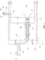
FIG. 1 is a schematic view of a condition measurement apparatus; -
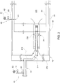
FIG. 2 is a schematic view of a condition measurement apparatus according to alternate embodiments; and -
FIG. 3 is a flow diagram illustrating a method of operating a gas turbine engine. - The detailed description explains embodiments of the invention, together with advantages and features, by way of example with reference to the drawings.
- With reference to
FIG. 1 , acondition measurement apparatus 10 is provided. Thecondition measurement apparatus 10 includes a gasturbine engine combustor 20 having acasing 21, aliner 22 disposed in thecasing 21 and formed to defme aninterior 220 and afuel nozzle 23. Thefuel nozzle 23 is communicative with theliner interior 220 such that fuel delivered to thefuel nozzle 23 can be injected into and mixed with an air flow viafuel injectors 230 with the fuel and air mixture then being supplied to and combusted within theliner interior 220. Thecasing 21 includes anend cover 210, which is formed to defme anorifice 211 upstream from thefuel nozzle 23 and amanifold 212. Fuel to be combusted in theliner interior 220 is deliverable to thefuel nozzle 23 by themanifold 212 via theorifice 211. - The
fuel nozzle 23 may be plural in number and may be provided in multiple groups of circuits with the fuel being similarly deliverable to each of theplural fuel nozzles 23. In particular, for a DLN combustor, thefuel nozzle 23 may be provided as a set of sixfuel nozzles 23 with one group of onefuel nozzle 23, one group of twofuel nozzles 23 and one group of threefuel nozzles 23. - The
end cover 210 may be formed to separate a "cold side" thereof from a "hot side" thereof. As used herein, the "cold side" refers to a relatively low temperature environment. By contrast, the "hot side" refers to a relatively high temperature environment. Theliner 22 and thefuel nozzle 23 are both operably disposed within the "hot side" of theend cover 210 with thefuel nozzle 23 extending at least from theend cover 210 to theliner 22. - The
condition measurement apparatus 10 further includes piping 30 and acondition sensing device 40. Thepiping 30 is disposed at the "cold side" of theend cover 210, which as described above is a relatively low temperature environment, and supplies the fuel to themanifold 212. Thecondition sensing device 40 is operably mounted on thepiping 30 and configured to sense a combustion dynamics generated acoustic pressure wave propagating upstream from theliner interior 220. To this end, thecondition sensing device 40 may include anacoustic pressure sensor 51 to sense acoustic pressure fluctuations in thepiping 30. - In accordance with embodiments and, as shown in
FIG. 1 , theacoustic pressure sensor 51 may be directly operably mounted on thepiping 30. In this case, a wave guide and an infinite or semi-infinite coil may be unnecessary and costs associated therewith avoided. By contrast, in accordance with alternate embodiments and, with reference toFIG. 2 , thecondition sensing device 40 may further include awave guide 52 and an infinite orsemi-infinite coil 53. Thewave guide 52 is operably interposed between theacoustic pressure sensor 51 and thepiping 30 and thereby transmits acoustic pressure fluctuations from thepiping 30 to theacoustic pressure sensor 51. The infinite orsemi-infinite coil 53 is fluidly coupled to theacoustic pressure sensor 51. In the case of the embodiments ofFIG. 2 , the "cold side" location of thecondition sensing device 40 may lead to extended durability and reliability of at least thewave guide 52. - With reference to
FIGS. 1 and2 , thecondition measurement apparatus 10 may further include an additionalcondition sensing device 60 operably disposed at the "hot side" of theend cover 210, which as described above is a relatively high temperature environment. The additionalcondition sensing device 60 may be operably mounted on theliner 22 at asensing hole 61 formed therein and may include anacoustic pressure sensor 62, awave guide 63 operably interposed between theacoustic pressure sensor 62 and theliner 22 and aninfinite coil 64 coupled to theacoustic pressure sensor 62 as described above. - With the
condition sensing device 40 sensing acoustic pressures at the "cold side" of theend cover 220 and theadditional sensing device 60 sensing acoustic pressures at the "hot side" of theend cover 220, thecondition measurement apparatus 10 may be provided with additional advantages beyond those of conventional systems. For example, thecondition sensing device 40 may be provided as a backup sensor to detect faulty liner sensor operations, which may occur due to extended exposure to hot gases. - In addition, with reference to
FIG. 3 , the use of thecondition sensing device 40 and theadditional sensing device 60 may also provide for a method of condition measurement for a gas turbine engine. The method may include measuring a condition, such as an acoustic pressure, at the "cold side" of the end cover 220 (operation 100), measuring the condition at the "hot side" of the end cover 220 (operation 110) and relating results of the condition measurements at the cold and hot sides of theend cover 220 to one another (operation 120) by, for example, deriving a transfer function describing acoustic pressure amplitude across theend cover 220. The method may further include evaluating an accuracy of the measuring (operation 130), where the evaluating is based on a relationship of results of the condition measurements (i.e., based on the transfer function). - Moreover, by deriving or establishing the transfer function of acoustic pressure amplitude between, for example, a standard liner location (i.e., the location of the additional condition sensing device 60) and an upstream fuel line location (i.e., the location of the condition sensing device 40), use of the
waveguide 63 at the standard liner location can be eliminated and cooling air can be used for premixing of more air and fuel, which may help to achieve a relatively decreased NOx emissions level. - Where the
fuel nozzle 23 is plural in number and provided in multiple groups of circuits with the fuel being similarly deliverable to each of theplural fuel nozzles 23, one or more of these circuits can be employed to develop the transfer function. - While the invention has been described in detail in connection with only a limited number of embodiments, it should be readily understood that the invention is not limited to such disclosed embodiments. Rather, the invention can be modified to incorporate any number of variations, alterations, substitutions or equivalent arrangements not heretofore described, but which are commensurate with the spirit and scope of the invention. Additionally, while various embodiments of the invention have been described, it is to be understood that aspects of the invention may include only some of the described embodiments. Accordingly, the invention is not to be seen as limited by the foregoing description, but is only limited by the scope of the appended claims.
Claims (12)
- A condition measurement apparatus (10), comprising:a gas turbine engine combustor (20) having an end cover (210), a liner (22) defining a liner interior (220) and a fuel nozzle (23) communicative with the liner interior (220),the end cover (210) being formed to separate a cold side thereof, which is a relatively low temperature environment, from a hot side thereof, which is a relatively high temperature environment in which the liner (22) and the fuel nozzle (23) are disposed,the combustor (20) being formed to define a fuel flow path extending through piping (30) disposed at the cold side of the end cover (210) by which fuel is deliverable to the fuel nozzle (23); anda condition sensing device (40) operably mounted on the piping (30).
- The condition measurement apparatus (10) according to claim 1, wherein the fuel nozzle (23) is plural in number and arranged in one group of one fuel nozzle (23), one group of two fuel nozzles (23) and one group of three fuel nozzles (23), the fuel being deliverable to each of the plural fuel nozzles (23).
- The condition measurement apparatus (10) according to claim 1 or 2, wherein the condition sensing device (40) senses a combustion dynamics generated acoustic pressure wave propagating in an upstream direction.
- The condition measurement apparatus (10) according to any of claims 1 to 3, wherein the condition sensing device comprises an acoustic pressure sensor (51).
- The condition measurement apparatus (10) according to claim 4, wherein the acoustic pressure sensor (51) is directly operably mounted on the piping (30).
- The condition measurement apparatus (10) according to claim 4 or 5, wherein the condition sensing device (40) further comprises:a wave guide (52) operably interposed between the acoustic pressure sensor and the piping; andan infinite or semi-infinite coil (53) coupled to the acoustic pressure sensor.
- The condition measurement apparatus (10) according to any preceding claim, further comprising an additional condition sensing device (60) operably disposed at the hot side of the end cover.
- The condition measurement apparatus (10) according to claim 7, wherein the additional condition sensing device (60) comprises:an acoustic pressure sensor (62); anda wave guide (63) and an infinite or semi-infinite coil (64) coupled to the acoustic pressure sensor (62).
- The condition measurement apparatus (10), of any preceding claim, wherein the liner (22) is disposed in a casing (21) of the gas turbine engine combustor (20), and wherein
the casing (21) further includes the end cover (210) which defines an orifice (211) upstream from the fuel nozzle (23) and a manifold (212) by which fuel to be combusted in the liner interior (220) is deliverable to the fuel nozzle (23) via the orifice (211);
and wherein the piping (30) supplies the fuel to the manifold (212). - A method of condition measurement for a gas turbine engine, comprising:measuring a condition at a cold side of a combustor end cover (100);measuring the condition at a hot side of the combustor end cover (110); andrelating results of the condition measurements at the cold and hot sides of the combustor end cover to one another (120).
- The method according to claim 10, wherein the measuring of the condition at the cold (100) and hot (110) sides of the combustor end cover comprises measuring acoustic pressures at the cold (100) and hot (110) sides of the combustor end cover.
- The method according to claim 10 or 11, further comprising evaluating an accuracy of the measuring based on a relationship of results of the condition measurements.
Applications Claiming Priority (1)
| Application Number | Priority Date | Filing Date | Title |
|---|---|---|---|
| US13/023,226 US8646278B2 (en) | 2011-02-08 | 2011-02-08 | Condition measurement apparatus and method |
Publications (1)
| Publication Number | Publication Date |
|---|---|
| EP2484977A2 true EP2484977A2 (en) | 2012-08-08 |
Family
ID=45607624
Family Applications (1)
| Application Number | Title | Priority Date | Filing Date |
|---|---|---|---|
| EP12154281A Withdrawn EP2484977A2 (en) | 2011-02-08 | 2012-02-07 | Condition measurement apparatus and method |
Country Status (3)
| Country | Link |
|---|---|
| US (1) | US8646278B2 (en) |
| EP (1) | EP2484977A2 (en) |
| CN (1) | CN102680070A (en) |
Families Citing this family (2)
| Publication number | Priority date | Publication date | Assignee | Title |
|---|---|---|---|---|
| US9423317B2 (en) * | 2013-12-31 | 2016-08-23 | Inventus Holdings, Llc | Combustion chamber measurement system |
| US11092083B2 (en) | 2017-02-10 | 2021-08-17 | General Electric Company | Pressure sensor assembly for a turbine engine |
Family Cites Families (16)
| Publication number | Priority date | Publication date | Assignee | Title |
|---|---|---|---|---|
| US3341118A (en) * | 1965-08-31 | 1967-09-12 | Combustion Eng | Burner elevation control system |
| JPS61241425A (en) * | 1985-04-17 | 1986-10-27 | Hitachi Ltd | Gas turbine fuel gas control method and control device |
| US4744670A (en) * | 1986-05-05 | 1988-05-17 | Honeywell, Inc. | Method and apparatus for monitoring the temperature of the propulsion gas at the inlet to a high-performance turbine wheel |
| US5148674A (en) * | 1990-01-26 | 1992-09-22 | Morris Brian G | Method and apparatus for providing real-time control of a gaseous propellant rocket propulsion system |
| US5116362A (en) * | 1990-12-03 | 1992-05-26 | United Technologies Corporation | Fuel metering and actuation system |
| US6813875B2 (en) * | 2000-01-07 | 2004-11-09 | Honda Giken Kogyo Kabushiki Kaisha | Control system for gas-turbine engine |
| JP3881871B2 (en) * | 2001-11-13 | 2007-02-14 | 三菱重工業株式会社 | Gas turbine fuel control method and control apparatus provided therefor |
| US6708568B2 (en) * | 2001-11-21 | 2004-03-23 | General Electric Company | Combustion chamber dynamic pressure transducer tee probe holder and related method |
| DE502004009162D1 (en) * | 2003-11-27 | 2009-04-23 | Siemens Ag | METHOD FOR DETERMINING SWAN FUEL PROPERTIES DURING OPERATING A POWER PLANT |
| US7775052B2 (en) * | 2004-05-07 | 2010-08-17 | Delavan Inc | Active combustion control system for gas turbine engines |
| US7464552B2 (en) * | 2004-07-02 | 2008-12-16 | Siemens Energy, Inc. | Acoustically stiffened gas-turbine fuel nozzle |
| WO2006069906A1 (en) * | 2004-12-23 | 2006-07-06 | Alstom Technology Ltd | Method for the operation of a gas turbo group |
| JP4119908B2 (en) * | 2005-09-14 | 2008-07-16 | 三菱重工業株式会社 | Combustion control device for gas turbine |
| JP4838763B2 (en) | 2007-06-11 | 2011-12-14 | 三菱重工業株式会社 | Mounting structure of combustion vibration detector |
| US8820087B2 (en) * | 2008-09-08 | 2014-09-02 | Siemens Energy, Inc. | Method and system for controlling fuel to a dual stage nozzle |
| CN101377159A (en) * | 2008-09-19 | 2009-03-04 | 海南嘉润动力有限公司 | Gas engine fuel digital control method and actuating device |
-
2011
- 2011-02-08 US US13/023,226 patent/US8646278B2/en not_active Expired - Fee Related
-
2012
- 2012-02-07 EP EP12154281A patent/EP2484977A2/en not_active Withdrawn
- 2012-02-08 CN CN2012100967608A patent/CN102680070A/en active Pending
Non-Patent Citations (1)
| Title |
|---|
| None |
Also Published As
| Publication number | Publication date |
|---|---|
| US20120198857A1 (en) | 2012-08-09 |
| CN102680070A (en) | 2012-09-19 |
| US8646278B2 (en) | 2014-02-11 |
Similar Documents
| Publication | Publication Date | Title |
|---|---|---|
| CN101900641B (en) | System and method for detecting a flame in a fuel nozzle of a gas turbine | |
| EP2778354B1 (en) | Variable heat/power ratio cogeneration system | |
| US9032703B2 (en) | Systems and methods for detecting combustor casing flame holding in a gas turbine engine | |
| US7966804B2 (en) | Method and apparatus for testing gas turbine engines | |
| US20130174649A1 (en) | Fluid leak detection system | |
| EP2383451A2 (en) | Alternate method for diluent injection for gas turbine NOx emissions control | |
| US20120196234A1 (en) | Combustion apparatus | |
| CN101876434A (en) | Fuel Nozzle Flashback Detection | |
| MX2009008076A (en) | Method of detecting a partial flame failure in a gas turbine engine and a gas turbine engine. | |
| EP2584176B1 (en) | Fuel system of a gas turbine | |
| WO2012084453A1 (en) | Method of detecting a predetermined condition in a gas turbine and failure detection system for a gas turbine | |
| US10612949B2 (en) | Plant, measurement system, and method for measuring temperature and velocity of a flow of fluid | |
| CN117307329B (en) | A method for monitoring backfire in a gas turbine and its combustion chamber | |
| US8646278B2 (en) | Condition measurement apparatus and method | |
| US9423317B2 (en) | Combustion chamber measurement system | |
| JP2009203883A (en) | Failure cause estimating method and device for internal combustion engine | |
| Huitenga et al. | Development approach to the dry low emission combustion system of MAN diesel and turbo gas turbines | |
| JP5841490B2 (en) | Gas turbine combustor, control device for gas turbine combustor, and abnormality detection method for gas turbine combustor | |
| US9909507B2 (en) | Control system for can-to-can variation in combustor system and related method | |
| CN105960564A (en) | Method for monitoring combustion installations | |
| CN113167610B (en) | Method for determining the flow rate of a combustible fluid injected into a combustion chamber without using an additional orifice plate | |
| US20260092820A1 (en) | Method and system for detecting errors in temperature readings in gas turbine engines | |
| Kim et al. | Performance Tests for Development of a Dry Low NOx Combustor | |
| JP2010117129A (en) | Gas supply device |
Legal Events
| Date | Code | Title | Description |
|---|---|---|---|
| PUAI | Public reference made under article 153(3) epc to a published international application that has entered the european phase |
Free format text: ORIGINAL CODE: 0009012 |
|
| AK | Designated contracting states |
Kind code of ref document: A2 Designated state(s): AL AT BE BG CH CY CZ DE DK EE ES FI FR GB GR HR HU IE IS IT LI LT LU LV MC MK MT NL NO PL PT RO RS SE SI SK SM TR |
|
| AX | Request for extension of the european patent |
Extension state: BA ME |
|
| STAA | Information on the status of an ep patent application or granted ep patent |
Free format text: STATUS: THE APPLICATION IS DEEMED TO BE WITHDRAWN |
|
| 18D | Application deemed to be withdrawn |
Effective date: 20140902 |