EP2484912A2 - Wet gas compressor systems - Google Patents
Wet gas compressor systems Download PDFInfo
- Publication number
- EP2484912A2 EP2484912A2 EP12153735A EP12153735A EP2484912A2 EP 2484912 A2 EP2484912 A2 EP 2484912A2 EP 12153735 A EP12153735 A EP 12153735A EP 12153735 A EP12153735 A EP 12153735A EP 2484912 A2 EP2484912 A2 EP 2484912A2
- Authority
- EP
- European Patent Office
- Prior art keywords
- section
- wet gas
- gas compressor
- size
- nozzle
- Prior art date
- Legal status (The legal status is an assumption and is not a legal conclusion. Google has not performed a legal analysis and makes no representation as to the accuracy of the status listed.)
- Granted
Links
Images



Classifications
-
- F—MECHANICAL ENGINEERING; LIGHTING; HEATING; WEAPONS; BLASTING
- F04—POSITIVE - DISPLACEMENT MACHINES FOR LIQUIDS; PUMPS FOR LIQUIDS OR ELASTIC FLUIDS
- F04D—NON-POSITIVE-DISPLACEMENT PUMPS
- F04D21/00—Pump involving supersonic speed of pumped fluids
-
- F—MECHANICAL ENGINEERING; LIGHTING; HEATING; WEAPONS; BLASTING
- F04—POSITIVE - DISPLACEMENT MACHINES FOR LIQUIDS; PUMPS FOR LIQUIDS OR ELASTIC FLUIDS
- F04D—NON-POSITIVE-DISPLACEMENT PUMPS
- F04D29/00—Details, component parts, or accessories
- F04D29/40—Casings; Connections of working fluid
- F04D29/42—Casings; Connections of working fluid for radial or helico-centrifugal pumps
- F04D29/4206—Casings; Connections of working fluid for radial or helico-centrifugal pumps especially adapted for elastic fluid pumps
- F04D29/4213—Casings; Connections of working fluid for radial or helico-centrifugal pumps especially adapted for elastic fluid pumps suction ports
-
- F—MECHANICAL ENGINEERING; LIGHTING; HEATING; WEAPONS; BLASTING
- F04—POSITIVE - DISPLACEMENT MACHINES FOR LIQUIDS; PUMPS FOR LIQUIDS OR ELASTIC FLUIDS
- F04D—NON-POSITIVE-DISPLACEMENT PUMPS
- F04D29/00—Details, component parts, or accessories
- F04D29/40—Casings; Connections of working fluid
- F04D29/42—Casings; Connections of working fluid for radial or helico-centrifugal pumps
- F04D29/44—Fluid-guiding means, e.g. diffusers
- F04D29/441—Fluid-guiding means, e.g. diffusers especially adapted for elastic fluid pumps
-
- F—MECHANICAL ENGINEERING; LIGHTING; HEATING; WEAPONS; BLASTING
- F04—POSITIVE - DISPLACEMENT MACHINES FOR LIQUIDS; PUMPS FOR LIQUIDS OR ELASTIC FLUIDS
- F04D—NON-POSITIVE-DISPLACEMENT PUMPS
- F04D29/00—Details, component parts, or accessories
- F04D29/58—Cooling; Heating; Diminishing heat transfer
- F04D29/582—Cooling; Heating; Diminishing heat transfer specially adapted for elastic fluid pumps
- F04D29/5846—Cooling; Heating; Diminishing heat transfer specially adapted for elastic fluid pumps cooling by injection
-
- F—MECHANICAL ENGINEERING; LIGHTING; HEATING; WEAPONS; BLASTING
- F04—POSITIVE - DISPLACEMENT MACHINES FOR LIQUIDS; PUMPS FOR LIQUIDS OR ELASTIC FLUIDS
- F04D—NON-POSITIVE-DISPLACEMENT PUMPS
- F04D31/00—Pumping liquids and elastic fluids at the same time
-
- F—MECHANICAL ENGINEERING; LIGHTING; HEATING; WEAPONS; BLASTING
- F05—INDEXING SCHEMES RELATING TO ENGINES OR PUMPS IN VARIOUS SUBCLASSES OF CLASSES F01-F04
- F05D—INDEXING SCHEME FOR ASPECTS RELATING TO NON-POSITIVE-DISPLACEMENT MACHINES OR ENGINES, GAS-TURBINES OR JET-PROPULSION PLANTS
- F05D2250/00—Geometry
- F05D2250/50—Inlet or outlet
- F05D2250/51—Inlet
Definitions
- the present application relates generally to wet gas compressor systems and more particularly relates to wet gas compressors with a variable cross-section flow conditioning nozzle therein so as to reduce erosion and other damage caused by liquid droplets in a wet gas.
- Natural gas and other types of liquid fuels may include a liquid component therein.
- Such "wet" gases may have a significant amount of liquid volume fraction.
- liquid droplets in such wet gases may cause erosion or embrittlement of the impellers and rotor unbalance resulting therefrom.
- the negative interaction between the liquid droplets and the compressor surfaces, such as impellers, end walls, seals, etc. may be significant. Erosion is known to be essentially a function of the relative velocity of the droplets during impact onto the compressor surfaces, droplet mass size, as well as the impact angle. Erosion may lead to performance degradation, reliability issues, reduced compressor lifetime, and increased maintenance requirements.
- such systems and methods may minimize the impact of erosion and other damage caused by liquid droplets in a wet gas while avoiding the need for liquid-gas separators and the like.
- the present application thus provides for a wet gas compressor system.
- the wet gas compressor system described herein may include a wet gas compressor with an inlet section.
- a variable cross-section nozzle may be positioned about the inlet section.
- the present application further provides a method of flow conditioning a gas flow with a number of liquid droplets therein before entry into a compressor.
- the method may include the steps of flowing the gas flow in a converging section of decreasing cross-sectional area and flowing the gas flow in a diverging section of increasing cross-sectional area.
- the gas flow accelerates in the converging section and the diverging section such that the liquid droplets breakup from a first size to a second size.
- the method further includes the step of flowing the gas flow across a shock point such that the liquid droplets breakup to a third size.
- the present application further provides for a wet gas compressor system.
- the wet gas compressor system may include a wet gas compressor with an inlet section and a number of stages.
- One or more convergent-divergent nozzles may be positioned about the inlet section or in-between the stages.
- a gas flow with a number of liquid droplets may pass therein.
- the liquid droplets may have a first size upstream of the convergent-divergent nozzles and a second size downstream of the convergent-divergent nozzles. The second size may be smaller than the first.
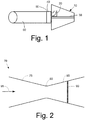
- Fig. 1 is a schematic view of a known wet gas compressor with a portion of a pipe section.
- Fig. 2 is a schematic view of an example of a known variable cross-section nozzle.
- Fig. 3 is a schematic view of a flow conditioning nozzle as may be described herein.
- Fig. 4 is a partial schematic view of a variable cross-section nozzle as may be described herein positioned about a radial inlet of a wet gas compressor.
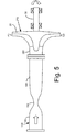
- Fig. 5 is a partial schematic view of a variable cross-section nozzle as may be described herein positioned about a radial inlet of a wet gas compressor.
- Fig. 6A is a plan view of a nozzle configuration as may be used herein.
- Fig. 6B is a plan view of a nozzle configuration as may be used herein.
- Fig. 7 is a partial schematic view of a variable section device positioned between consecutive stages.
- Fig. 1 shows an example of a known wet gas compressor 10.
- the wet gas compressor 10 may be of conventional design and may include a number of stages with a numbers of impellers 20 positioned on a shaft 30 for rotation therewith as well as a number of stators.
- the wet gas compressor 10 also may include an inlet section 40.
- the inlet section 40 may be an inlet scroll 50 and the like positioned about the impellers 20.
- Other types and configurations of wet gas compressors 10 may be known.
- a pipe section 60 may be in communication with the inlet section 40 of the wet gas compressor 10.
- the pipe section 60 may be of any desired size, shape, or length. Any number of pipe sections 60 may be used herein.
- Fig. 2 shows a known variable cross-section nozzle 70.
- the variable cross-section nozzle 70 may be a convergent-divergent nozzle also is known as a de Laval nozzle and the like.
- the variable cross-section nozzle 70 may include a convergent section 75 with a decreasing cross-sectional area.
- the convergent section 75 may lead to a throat section 80 of essentially constant cross-sectional area.
- the throat section 80 generally has some length as opposed to being merely a point of smallest diameter.
- the throat section 80 in turn leads to a divergent section 85 of increasing cross-sectional area.
- a shock point 90 may be positioned within the divergent section 85 downstream of the throat section 80.
- the length of the sections 75, 80, 85 as well as the angle of increasing and decreasing cross-sectional areas may vary.
- the variable cross-section nozzle 70 includes a sequence of sections that provide flow acceleration and/or deceleration to promote a non-zero relative velocity between gaseous and liquid phases.
- the sections 75, 80, 85 may be symmetric or asymmetric. Other configurations may be used herein.
- a gas flow 95 enters the variable cross-section nozzle 70 about the convergent section 75.
- the speed of the gas flow 95 may be largely subsonic at this point.
- the speed of the gas flow 95 will increase in the decreasing cross-sectional area of the convergent section 75.
- the gas flow 95 then may expand and may increase to supersonic velocity in the divergent section 85 at about the shock point 90.
- the kinetic energy of the gas flow 95 leaving the variable cross-section nozzle 70 thus may be closely directed.
- Other types of variable cross-section nozzle designs may be known. For example, without the use of a throat section 80 of some length, the gas flow 95 may or may not increase to supersonic speeds and may or may not develop a shock point.
- Fig. 3 shows portions of a wet gas compressor system 100 as may be described herein.
- the wet gas compressor system 100 may include the wet gas compressor 10 described above or a similar type of compressor.
- the wet gas compressor 10 may be in communication with the pipe section 60 or similar types of conduits.
- the wet gas compressor system 100 may include an inlet section 110.
- the inlet section 110 may be positioned about the impellers 20 of the wet gas compressor 10.
- the inlet section 110 may include one or more flow conditioning nozzles 120 therein.
- the flow conditioning nozzle 120 may take the form of a convergent-divergent or a variable cross-section nozzle 130 similar to that described above.
- the variable cross-section nozzle 130 may include some or all of a convergent section 140, a throat section 150, a divergent section 160, and a shock point 170.
- the relative sizes, lengths, and angles of the respective sections 140, 150, 160 may be varied. As above, the length of the sections 140, 150, 160 as well as the angle of increasing and decreasing cross-sectional areas may vary.
- the sections 140, 150, 160 may be symmetric or asymmetric.
- the variable cross-section nozzle 130 may be largely circular and axis-symmetric or quasi two-dimensional. Other configurations may be used herein.
- the flow conditioning nozzle 120 may be used with a gas flow 180 having a high liquid volume fraction due to a number of liquid droplets 190 therein.
- variable cross-section nozzle 130 need not include a throat section 150 of any length.
- the gas flow 180 thus may or may not reach supersonic speeds without such a throat section 150.
- no shock point 170 will develop downstream in the divergent section 160.
- variable cross-section nozzle 130 may be almost all just the convergent section 140.
- the use of the flow conditioning nozzle 120 about the wet gas compressor 10 preferably may minimize the interaction between the liquid droplets 190 and the impellers 20 and the other surfaces of the wet gas compressor 10.
- the flow conditioning nozzle 120 may provide secondary atomization of the liquid droplets 190 via the rapid changes in the velocity of the gas flow 180 due to the shape of the variable cross-section nozzle 130.
- the slip velocity between the gas flow 180 and the liquid droplets 190 may exceed critical values required for liquid droplet breakup.
- the size and design of the sections 140, 150, 160 of the variable cross-section nozzle 130 may control the rate of acceleration or deceleration therein as well as the shock strength so as to induce breakup as well as the type or mode of breakup.
- bag-type breakup, shear-type breakup, and the like may be induced herein.
- the divergent section 160 may have a relatively small angle so as to minimize the rate of gas acceleration and hence the slip velocity so as to prevent premature bag-type breakup and promote shear-type breakup downstream of the shock point 170.
- Bag-type breakup may reduce the size of the liquid droplets 190 by about 3.5 to 1 while shear-type breakup may reduce the size of the liquid droplets 190 by about 10 to 1.
- Other types of breakup modes may be used herein. For example, Multi-mode breakup (between bag and shear breakup) and catastrophic breakup also may be used.
- the size of liquid droplets 190 tends to decrease as the cross-sectional area of the convergent section 140 decreases, i.e., positive slip. Likewise, the size of liquid droplets 190 may continue to decrease, although not as steeply, as the cross-sectional area of the divergent section 160 increases, i.e., again positive slip. A sharp decrease in the size of the liquid droplets 190 may be expected about the shock point 170, i.e., instantaneous slip reversal. The size of liquid droplets 190 may remain substantially constant thereafter, i.e., negative slip.
- the liquid droplets 190 may have a first size 200 entering the flow conditioning nozzle, a smaller or a number of smaller second sizes 210 passing through the convergent section 140, the throat 150, and entering into the divergent section 160, and a smaller third size 220 downstream of the shock point 170.
- More than one breakup of the liquid droplets 190 may take place. For example, rapid acceleration of the gas flow 180 in the convergent section 140 may induce a first round breakup of the liquid droplets 190. A second round of breakup may be achieved by the rapid deceleration of the gas flow 180 as it passes through the shock point 170 and the diversion section 160. Each round of breakup may have the same or a different mode of breakup.
- the gas flow 180 thus may be accelerated through one or more flow conditioning nozzles 120 such that the liquid droplets 190 therein breakup one or more times until the desired droplet size may be achieved.
- the flow conditioning nozzle 120 may be both subsonic and supersonic depending upon the amount of acceleration required for droplet breakup and how many breakup steps may be desired to achieve a specific drop size. For a subsonic nozzle, droplet breakup may be induced by flow acceleration therethrough. For supersonic nozzles, breakup also may be induced when the droplets pass through a single or series of normal or oblique shocks.
- the flow conditioning nozzle 120 also may be used with appropriately shaped guide vanes so as to induce a preswirl into the gas flow 180 so as to reduce the relative velocity between the impellers 20 and the liquid droplets 190.
- the liquid droplets 190 may provide intercooling of the gas flow 180 during compression as the gas flow 180 reaches the wet gas compressor 10. Specifically, reducing the size of the liquid droplets 190, as described above, thus may maximize the intercooling benefit. Likewise, promoting evaporation of the liquid droplets 190 in multistage compressors also may be enhanced by minimizing the size of the liquid droplets 190. Sufficiently small liquid droplets 190 may tend to follow the streamline of the gas flow 180 so as to reduce the overall interaction with the surfaces of the wet gas compressor 10. Specifically, smaller liquid droplets 190 may lead to more favorable impingement angles, reduced momentum during impact, and enhanced evaporation while maximizing intercooling and reducing liquid volume fractions.
- the overall lifetime and reliability of the compressor 10 thus may be enhanced for a given amount of gas flow in terms of the liquid volume fraction. Moreover, the amount of liquid that a compressor 10 may tolerate under certain boundary conditions also may be increased without compromising overall lifetime and reliability. Significantly, the flow conditioning nozzle 120 provides these benefits without any moving parts.
- the fluid conditioning nozzle 120 need not be a separate element. Rather, the shape of the variable cross-section nozzle 130 may be within an inlet scroll 50, within a pipe section 60, or by shaping any type of end wall such as a shroud wall, a hub wall, and the like. One large flow conditioning nozzle 120 may be used or a number of smaller nozzles may be arranged circumferentially within the inlet scroll 50, the pipe section 60, or otherwise.
- Figs. 4 and 5 show the use of the variable cross-section nozzle 130 about wet gas compressors 10 having inlet sections 40 of varying configurations.
- Fig. 4 shows a wet gas compressor 250 with a radial inlet section 260.
- the variable cross-section nozzle 130 thus may be positioned in a radial direction.
- Fig. 5 shows a wet gas compressor 270 with an axial inlet section 280.
- the variable cross-section nozzle 130 thus may have an axial position.
- Other positions and other types of wet gas compressors may be used herein.
- the variable cross-section nozzles 130 may be used with overhung compressors, beamed compressors, and the like. Other configurations may be used herein.
- Figs. 6A and 6B show two possible nozzle configurations 300, 310 for use with the variable cross-section nozzle described herein.
- Fig. 7 shows a multistage arrangement 320 in which an additional converging section 330 may be applied between consecutive stages.
- the nozzle configurations 300 and 310 may be used also in conjunction with the radial inlet section 260 and the like.
Landscapes
- Engineering & Computer Science (AREA)
- Mechanical Engineering (AREA)
- General Engineering & Computer Science (AREA)
- Physics & Mathematics (AREA)
- Thermal Sciences (AREA)
- Structures Of Non-Positive Displacement Pumps (AREA)
Abstract
Description
- The present application relates generally to wet gas compressor systems and more particularly relates to wet gas compressors with a variable cross-section flow conditioning nozzle therein so as to reduce erosion and other damage caused by liquid droplets in a wet gas.
- Natural gas and other types of liquid fuels may include a liquid component therein. Such "wet" gases may have a significant amount of liquid volume fraction. In conventional compressors, liquid droplets in such wet gases may cause erosion or embrittlement of the impellers and rotor unbalance resulting therefrom. Specifically, the negative interaction between the liquid droplets and the compressor surfaces, such as impellers, end walls, seals, etc., may be significant. Erosion is known to be essentially a function of the relative velocity of the droplets during impact onto the compressor surfaces, droplet mass size, as well as the impact angle. Erosion may lead to performance degradation, reliability issues, reduced compressor lifetime, and increased maintenance requirements.
- Current wet gas compressors thus generally separate the liquid droplets from the gas stream so as to limit or at least localize the impact of erosion and other damage caused by the liquid droplets. These known liquid separation systems and techniques, however, tend to be somewhat complex and likewise may add further reliability and maintenance issues to the compressor as a whole.
- There is thus a desire for improved wet gas compression systems and methods. Preferably, such systems and methods may minimize the impact of erosion and other damage caused by liquid droplets in a wet gas while avoiding the need for liquid-gas separators and the like.
- The present application thus provides for a wet gas compressor system. The wet gas compressor system described herein may include a wet gas compressor with an inlet section. A variable cross-section nozzle may be positioned about the inlet section.
- The present application further provides a method of flow conditioning a gas flow with a number of liquid droplets therein before entry into a compressor. The method may include the steps of flowing the gas flow in a converging section of decreasing cross-sectional area and flowing the gas flow in a diverging section of increasing cross-sectional area. The gas flow accelerates in the converging section and the diverging section such that the liquid droplets breakup from a first size to a second size. The method further includes the step of flowing the gas flow across a shock point such that the liquid droplets breakup to a third size.
- The present application further provides for a wet gas compressor system. The wet gas compressor system may include a wet gas compressor with an inlet section and a number of stages. One or more convergent-divergent nozzles may be positioned about the inlet section or in-between the stages. A gas flow with a number of liquid droplets may pass therein. The liquid droplets may have a first size upstream of the convergent-divergent nozzles and a second size downstream of the convergent-divergent nozzles. The second size may be smaller than the first.
- These and other features and improvements of the present application will become apparent to one of ordinary skill in the art upon review of the following detailed description when taken in conjunction with the several drawings and the appended claims.
-
Fig. 1 is a schematic view of a known wet gas compressor with a portion of a pipe section. -
Fig. 2 is a schematic view of an example of a known variable cross-section nozzle. -
Fig. 3 is a schematic view of a flow conditioning nozzle as may be described herein. -
Fig. 4 is a partial schematic view of a variable cross-section nozzle as may be described herein positioned about a radial inlet of a wet gas compressor. -
Fig. 5 is a partial schematic view of a variable cross-section nozzle as may be described herein positioned about a radial inlet of a wet gas compressor. -
Fig. 6A is a plan view of a nozzle configuration as may be used herein. -
Fig. 6B is a plan view of a nozzle configuration as may be used herein. -
Fig. 7 is a partial schematic view of a variable section device positioned between consecutive stages. - Referring now to the drawings, in which like numbers refer to like elements throughout the several views,
Fig. 1 shows an example of a knownwet gas compressor 10. Thewet gas compressor 10 may be of conventional design and may include a number of stages with a numbers ofimpellers 20 positioned on ashaft 30 for rotation therewith as well as a number of stators. Thewet gas compressor 10 also may include aninlet section 40. Theinlet section 40 may be aninlet scroll 50 and the like positioned about theimpellers 20. Other types and configurations ofwet gas compressors 10 may be known. Apipe section 60 may be in communication with theinlet section 40 of thewet gas compressor 10. Thepipe section 60 may be of any desired size, shape, or length. Any number ofpipe sections 60 may be used herein. -
Fig. 2 shows a knownvariable cross-section nozzle 70. Thevariable cross-section nozzle 70 may be a convergent-divergent nozzle also is known as a de Laval nozzle and the like. Generally described, thevariable cross-section nozzle 70 may include aconvergent section 75 with a decreasing cross-sectional area. Theconvergent section 75 may lead to athroat section 80 of essentially constant cross-sectional area. Thethroat section 80 generally has some length as opposed to being merely a point of smallest diameter. Thethroat section 80 in turn leads to adivergent section 85 of increasing cross-sectional area. Ashock point 90 may be positioned within thedivergent section 85 downstream of thethroat section 80. The length of thesections variable cross-section nozzle 70 includes a sequence of sections that provide flow acceleration and/or deceleration to promote a non-zero relative velocity between gaseous and liquid phases. Thesections - Generally described, a
gas flow 95 enters thevariable cross-section nozzle 70 about theconvergent section 75. The speed of thegas flow 95 may be largely subsonic at this point. The speed of thegas flow 95 will increase in the decreasing cross-sectional area of theconvergent section 75. Thegas flow 95 then may expand and may increase to supersonic velocity in thedivergent section 85 at about theshock point 90. The kinetic energy of thegas flow 95 leaving thevariable cross-section nozzle 70 thus may be closely directed. Other types of variable cross-section nozzle designs may be known. For example, without the use of athroat section 80 of some length, thegas flow 95 may or may not increase to supersonic speeds and may or may not develop a shock point. -
Fig. 3 shows portions of a wetgas compressor system 100 as may be described herein. The wetgas compressor system 100 may include thewet gas compressor 10 described above or a similar type of compressor. Likewise, thewet gas compressor 10 may be in communication with thepipe section 60 or similar types of conduits. - The wet
gas compressor system 100 may include aninlet section 110. Theinlet section 110 may be positioned about theimpellers 20 of thewet gas compressor 10. Theinlet section 110 may include one or moreflow conditioning nozzles 120 therein. Theflow conditioning nozzle 120 may take the form of a convergent-divergent or avariable cross-section nozzle 130 similar to that described above. Specifically, thevariable cross-section nozzle 130 may include some or all of aconvergent section 140, athroat section 150, adivergent section 160, and ashock point 170. The relative sizes, lengths, and angles of therespective sections sections sections variable cross-section nozzle 130 may be largely circular and axis-symmetric or quasi two-dimensional. Other configurations may be used herein. Theflow conditioning nozzle 120 may be used with agas flow 180 having a high liquid volume fraction due to a number ofliquid droplets 190 therein. - Not all of the
sections variable cross-section nozzle 130 need not include athroat section 150 of any length. Thegas flow 180 thus may or may not reach supersonic speeds without such athroat section 150. In the subsonic case, noshock point 170 will develop downstream in thedivergent section 160. Moreover, thevariable cross-section nozzle 130 may be almost all just theconvergent section 140. - The use of the
flow conditioning nozzle 120 about thewet gas compressor 10 preferably may minimize the interaction between theliquid droplets 190 and theimpellers 20 and the other surfaces of thewet gas compressor 10. Specifically, theflow conditioning nozzle 120 may provide secondary atomization of theliquid droplets 190 via the rapid changes in the velocity of thegas flow 180 due to the shape of thevariable cross-section nozzle 130. - Specifically, the slip velocity between the
gas flow 180 and theliquid droplets 190 may exceed critical values required for liquid droplet breakup. The size and design of thesections variable cross-section nozzle 130 may control the rate of acceleration or deceleration therein as well as the shock strength so as to induce breakup as well as the type or mode of breakup. For example, bag-type breakup, shear-type breakup, and the like may be induced herein. As such, thedivergent section 160 may have a relatively small angle so as to minimize the rate of gas acceleration and hence the slip velocity so as to prevent premature bag-type breakup and promote shear-type breakup downstream of theshock point 170. Bag-type breakup may reduce the size of theliquid droplets 190 by about 3.5 to 1 while shear-type breakup may reduce the size of theliquid droplets 190 by about 10 to 1. Other types of breakup modes may be used herein. For example, Multi-mode breakup (between bag and shear breakup) and catastrophic breakup also may be used. - The size of
liquid droplets 190 tends to decrease as the cross-sectional area of theconvergent section 140 decreases, i.e., positive slip. Likewise, the size ofliquid droplets 190 may continue to decrease, although not as steeply, as the cross-sectional area of thedivergent section 160 increases, i.e., again positive slip. A sharp decrease in the size of theliquid droplets 190 may be expected about theshock point 170, i.e., instantaneous slip reversal. The size ofliquid droplets 190 may remain substantially constant thereafter, i.e., negative slip. Given such, theliquid droplets 190 may have afirst size 200 entering the flow conditioning nozzle, a smaller or a number of smallersecond sizes 210 passing through theconvergent section 140, thethroat 150, and entering into thedivergent section 160, and a smallerthird size 220 downstream of theshock point 170. - More than one breakup of the
liquid droplets 190 may take place. For example, rapid acceleration of thegas flow 180 in theconvergent section 140 may induce a first round breakup of theliquid droplets 190. A second round of breakup may be achieved by the rapid deceleration of thegas flow 180 as it passes through theshock point 170 and thediversion section 160. Each round of breakup may have the same or a different mode of breakup. - The
gas flow 180 thus may be accelerated through one or moreflow conditioning nozzles 120 such that theliquid droplets 190 therein breakup one or more times until the desired droplet size may be achieved. Theflow conditioning nozzle 120 may be both subsonic and supersonic depending upon the amount of acceleration required for droplet breakup and how many breakup steps may be desired to achieve a specific drop size. For a subsonic nozzle, droplet breakup may be induced by flow acceleration therethrough. For supersonic nozzles, breakup also may be induced when the droplets pass through a single or series of normal or oblique shocks. Theflow conditioning nozzle 120 also may be used with appropriately shaped guide vanes so as to induce a preswirl into thegas flow 180 so as to reduce the relative velocity between theimpellers 20 and theliquid droplets 190. - By allowing the
gas flow 180 to containliquid droplets 190 therein, theliquid droplets 190 may provide intercooling of thegas flow 180 during compression as thegas flow 180 reaches thewet gas compressor 10. Specifically, reducing the size of theliquid droplets 190, as described above, thus may maximize the intercooling benefit. Likewise, promoting evaporation of theliquid droplets 190 in multistage compressors also may be enhanced by minimizing the size of theliquid droplets 190. Sufficiently smallliquid droplets 190 may tend to follow the streamline of thegas flow 180 so as to reduce the overall interaction with the surfaces of thewet gas compressor 10. Specifically, smallerliquid droplets 190 may lead to more favorable impingement angles, reduced momentum during impact, and enhanced evaporation while maximizing intercooling and reducing liquid volume fractions. - The overall lifetime and reliability of the
compressor 10 thus may be enhanced for a given amount of gas flow in terms of the liquid volume fraction. Moreover, the amount of liquid that acompressor 10 may tolerate under certain boundary conditions also may be increased without compromising overall lifetime and reliability. Significantly, theflow conditioning nozzle 120 provides these benefits without any moving parts. - The
fluid conditioning nozzle 120 need not be a separate element. Rather, the shape of thevariable cross-section nozzle 130 may be within aninlet scroll 50, within apipe section 60, or by shaping any type of end wall such as a shroud wall, a hub wall, and the like. One largeflow conditioning nozzle 120 may be used or a number of smaller nozzles may be arranged circumferentially within theinlet scroll 50, thepipe section 60, or otherwise. -
Figs. 4 and5 show the use of thevariable cross-section nozzle 130 aboutwet gas compressors 10 havinginlet sections 40 of varying configurations. For example,Fig. 4 shows awet gas compressor 250 with aradial inlet section 260. Thevariable cross-section nozzle 130 thus may be positioned in a radial direction. Likewise,Fig. 5 shows awet gas compressor 270 with anaxial inlet section 280. Thevariable cross-section nozzle 130 thus may have an axial position. Other positions and other types of wet gas compressors may be used herein. For example, thevariable cross-section nozzles 130 may be used with overhung compressors, beamed compressors, and the like. Other configurations may be used herein. -
Figs. 6A and 6B show twopossible nozzle configurations Fig. 7 shows amultistage arrangement 320 in which an additional convergingsection 330 may be applied between consecutive stages. Thenozzle configurations radial inlet section 260 and the like. - It should be apparent that the foregoing relates only to certain embodiments of the present application and that numerous changes and modifications may be made herein by one of ordinary skill in the art without departing from the general spirit and scope of the invention as defined by the following claims and the equivalents thereof.
- Various aspects and embodiments of the present invention are defined by the following numbered clauses:
- 1. A wet gas compressor system, comprising:
- a wet gas compressor;
- the wet gas compressor comprises an inlet section; and
- a variable cross-section nozzle positioned about the inlet section.
- 2. The wet gas compressor system of clause 1, wherein the inlet section comprises a radial inlet section or an axial inlet section.
- 3. The wet gas compressor system of clause 1 or clause 2, wherein the variable cross-section nozzle comprises a throat section.
- 4. The wet gas compressor system of any preceding clause, wherein the variable cross-section nozzle comprises a divergent section.
- 5. The wet gas compressor system of any preceding clause, wherein the divergent section comprises a shock point.
- 6. The wet gas compressor system of any preceding clause, wherein the wet gas compressor comprises a plurality of impellers therein and wherein the variable cross-section nozzle is positioned about the plurality of impellers.
- 7. The wet gas compressor system of any preceding clause, further comprising a plurality of variable cross-section nozzles.
- 8. The wet gas compressor system of any preceding clause, wherein the inlet section comprises an inlet scroll.
- 9. The wet gas compressor system of any preceding clause, wherein the inlet section comprises a pipe section.
- 10. The wet gas compressor system of any preceding clause, further comprising a gas flow with a plurality of liquid droplets therein.
- 11. The wet gas compressor system of any preceding clause, wherein the gas flow comprises a subsonic speed.
- 12. The wet gas compressor system of any preceding clause, wherein the gas flow comprises a supersonic speed.
- 13. The wet gas compressor system of any preceding clause, wherein the plurality of liquid droplets comprises a first size upstream of the variable cross-section nozzle and a second size downstream of the variable cross-section nozzle and wherein the second size is smaller than the first size.
- 14. The wet gas compressor system of any preceding clause, wherein the variable cross-section nozzle is positioned between a plurality of stages.
- 15. A method of flow conditioning a gas flow with a plurality of liquid droplets therein before entry into a compressor, comprising:
- flowing the gas flow in a converging section of decreasing cross-sectional area;
- flowing the gas flow in a diverging section of increasing cross-sectional area;
- wherein the gas flow accelerates in the converging section and the diverging section such that the plurality of liquid droplets breakup from a first size to a second size; and
- flowing the gas flow across a shock point such that the plurality of liquid droplets breakup to a third size.
- 16. The method of any preceding clause, wherein the second size is smaller than the first size and wherein the third size is smaller than the second size.
- 17. The method of any preceding clause, wherein the flowing steps comprise a subsonic velocity.
- 18. The method of any preceding clause, wherein the flowing steps comprise a supersonic velocity.
- 19. A wet gas compressor system, comprising:
- a wet gas compressor;
- the wet gas compressor comprises an inlet section and a plurality of stages;
- one or more convergent-divergent nozzles positioned about the inlet section;
and - a gas flow with a plurality of liquid droplets therein;
- wherein the plurality of liquid droplets comprises a first size upstream of the one or more convergent-divergent nozzles and a second size downstream of the one or more convergent-divergent nozzles and wherein the second size is smaller than the first size.
- 20. The wet gas compressor system of any preceding clause, wherein the convergent-divergent nozzle is positioned between a pair of the plurality of stages.
Claims (15)
- A wet gas compressor system (100), comprising:a wet gas compressor (10);the wet gas compressor comprises an inlet section (110); anda variable cross-section nozzle (130) positioned about the inlet section (110).
- The wet gas compressor system (100) of claim 1, wherein the inlet section (110) comprises a radial inlet section (260) or an axial inlet section (280).
- The wet gas compressor system (100) of claim 1 or claim 2, wherein the variable cross-section nozzle (130) comprises a throat section (150).
- The wet gas compressor system (100) of any preceding claim, wherein the variable cross-section nozzle (130) comprises a divergent section (160).
- The wet gas compressor system (100) of any preceding claim, wherein the divergent section (160) comprises a shock point (170).
- The wet gas compressor system (100) of any preceding claim, wherein the wet gas compressor (10) comprises a plurality of impellers (20) therein and wherein the variable cross-section nozzle (130) is positioned about the plurality of impellers (20).
- The wet gas compressor system (100) of any preceding claim, further comprising a plurality of variable cross-section nozzles (130).
- The wet gas compressor system (100) of any preceding claim, wherein the inlet section (110) comprises an inlet scroll (50).
- The wet gas compressor system (100) of any preceding claim, wherein the inlet section (110) comprises a pipe section (60).
- The wet gas compressor system (100) of any preceding claim, further comprising a gas flow (180) with a plurality of liquid droplets (190) therein.
- The wet gas compressor system (100) of any preceding claim, wherein the gas flow (180) comprises a subsonic speed.
- The wet gas compressor system (100) of any preceding claim, wherein the gas flow (180) comprises a supersonic speed.
- The wet gas compressor system (100) of any preceding claim, wherein the plurality of liquid droplets (190) comprises a first size (200) upstream of the convergent-divergent nozzle (130) and a second size (210) downstream of the convergent-divergent nozzle (130) and wherein the second size (210) is smaller than the first size (200).
- A method of flow conditioning a gas flow (180) with a plurality of liquid droplets (190) therein before entry into a compressor (10), comprising:flowing the gas flow (180) in a converging section (140) of decreasing cross-sectional area;flowing the gas flow (180) in a diverging section (160) of increasing cross-sectional area;wherein the gas flow (180) accelerates in the converging section (140) and the diverging section (160) such that the plurality of liquid droplets (190) breakup from a first size (200) to a second size (210); andflowing the gas flow (180) across a shock point (170) such that the plurality of liquid droplets (190) breakup to a third size (220).
- The method of claim 14, wherein the second size (210) is smaller than the first size (200) and wherein the third size (220) is smaller than the second size (210).
Applications Claiming Priority (1)
| Application Number | Priority Date | Filing Date | Title |
|---|---|---|---|
| US13/020,873 US8690519B2 (en) | 2011-02-04 | 2011-02-04 | Wet gas compressor systems |
Publications (3)
| Publication Number | Publication Date |
|---|---|
| EP2484912A2 true EP2484912A2 (en) | 2012-08-08 |
| EP2484912A3 EP2484912A3 (en) | 2018-05-02 |
| EP2484912B1 EP2484912B1 (en) | 2019-11-27 |
Family
ID=45562818
Family Applications (1)
| Application Number | Title | Priority Date | Filing Date |
|---|---|---|---|
| EP12153735.1A Active EP2484912B1 (en) | 2011-02-04 | 2012-02-02 | Wet gas compressor systems |
Country Status (7)
| Country | Link |
|---|---|
| US (1) | US8690519B2 (en) |
| EP (1) | EP2484912B1 (en) |
| JP (1) | JP6001867B2 (en) |
| CN (1) | CN102628449B (en) |
| AU (1) | AU2012200632A1 (en) |
| IN (1) | IN2012DE00274A (en) |
| RU (1) | RU2584395C2 (en) |
Cited By (1)
| Publication number | Priority date | Publication date | Assignee | Title |
|---|---|---|---|---|
| WO2015127410A3 (en) * | 2014-02-24 | 2016-06-23 | Ge Oil & Gas Esp, Inc. | Downhole wet gas compressor processor |
Families Citing this family (10)
| Publication number | Priority date | Publication date | Assignee | Title |
|---|---|---|---|---|
| JP6736553B2 (en) * | 2014-12-12 | 2020-08-05 | ゼネラル・エレクトリック・カンパニイ | System and method for regulating the flow of a wet gas stream |
| US9181961B1 (en) * | 2015-02-17 | 2015-11-10 | Borgwarner Inc. | Compressor intake noise prevention by choking flow with duct geometry |
| ITUA20161464A1 (en) * | 2016-03-08 | 2017-09-08 | Nuovo Pignone Tecnologie Srl | Centrifugal compressor without external drainage system, motor compressor and method of avoiding external drainage in a compressor / Centrifugal compressor without external drainage system, motor compressor and method to avoid external drainage in a compressor |
| WO2020263617A1 (en) * | 2019-06-28 | 2020-12-30 | Carrier Corporation | Vaneless supersonic diffuser for compressor |
| US20230265862A1 (en) | 2022-02-21 | 2023-08-24 | General Electric Company | Turbofan engine having angled inlet pre-swirl vanes |
| US11725526B1 (en) | 2022-03-08 | 2023-08-15 | General Electric Company | Turbofan engine having nacelle with non-annular inlet |
| US12209557B1 (en) | 2023-11-30 | 2025-01-28 | General Electric Company | Gas turbine engine with forward swept outlet guide vanes |
| US12385430B2 (en) | 2023-11-30 | 2025-08-12 | General Electric Company | Gas turbine engine with forward swept outlet guide vanes |
| US12228037B1 (en) | 2023-12-04 | 2025-02-18 | General Electric Company | Guide vane assembly with fixed and variable pitch inlet guide vanes |
| US12313021B1 (en) | 2024-03-14 | 2025-05-27 | General Electric Company | Outer nacelle with inlet guide vanes and acoustic treatment |
Family Cites Families (18)
| Publication number | Priority date | Publication date | Assignee | Title |
|---|---|---|---|---|
| US4336820A (en) * | 1978-08-31 | 1982-06-29 | Parker-Hannifin Corporation | Metering device for adding one fluid to another |
| US4257733A (en) * | 1978-12-26 | 1981-03-24 | Carrier Corporation | Diffuser control |
| JPS5666404A (en) * | 1979-10-31 | 1981-06-04 | Toshiba Corp | Total flow turbine |
| SE456687B (en) * | 1982-01-04 | 1988-10-24 | Gen Electric | Centrifugal compressor with injection of a removable liquid |
| RU2140576C1 (en) * | 1995-12-07 | 1999-10-27 | Камский политехнический институт | Turbo-compressor |
| US5867977A (en) * | 1996-05-14 | 1999-02-09 | The Dow Chemical Company | Method and apparatus for achieving power augmentation in gas turbines via wet compression |
| FR2774137B1 (en) | 1998-01-28 | 2000-02-18 | Inst Francais Du Petrole | WET GAS COMPRESSION DEVICE COMPRISING AN INTEGRATED COMPRESSION / SEPARATION STAGE |
| US6793175B1 (en) * | 1999-08-25 | 2004-09-21 | The Boeing Company | Supersonic external-compression diffuser and method for designing same |
| CN1272094C (en) * | 1999-11-09 | 2006-08-30 | 纳幕尔杜邦公司 | Liquid jet compressor |
| DE10050697A1 (en) * | 2000-10-13 | 2002-04-18 | Alstom Switzerland Ltd | Isothermal compression process for gaseous medium involves use of convergent-divergent jet device after diffuser |
| AU2003205939A1 (en) * | 2002-02-19 | 2003-09-09 | Alstom Technology Ltd | Turboblower and method for operating such a turboblower |
| RU2267654C2 (en) * | 2004-01-14 | 2006-01-10 | Наумейко Валентина Михайловна | Automobile-mounted gas-filling compressor station |
| US7798777B2 (en) * | 2006-12-15 | 2010-09-21 | General Electric Company | Engine compressor assembly and method of operating the same |
| US7632339B2 (en) * | 2006-12-18 | 2009-12-15 | General Electric Company | Moisture removal apparatus and method |
| CN100570161C (en) * | 2007-09-28 | 2009-12-16 | 大连海事大学 | Hollow shaft rotary stamping compression rotor based on shock wave compression technology |
| US20090165864A1 (en) * | 2007-12-26 | 2009-07-02 | Rolls-Royce North American Technologies, Inc. | Supersonic inlet |
| US8167980B2 (en) * | 2008-08-28 | 2012-05-01 | General Electric Company | Filtration system for gas turbines |
| RU2530045C2 (en) * | 2009-02-12 | 2014-10-10 | Хартлэнд Текнолоджи Партнерс Ллк | Compact effluents concentrator running on waste heat |
-
2011
- 2011-02-04 US US13/020,873 patent/US8690519B2/en active Active
-
2012
- 2012-01-31 IN IN274DE2012 patent/IN2012DE00274A/en unknown
- 2012-02-02 EP EP12153735.1A patent/EP2484912B1/en active Active
- 2012-02-03 JP JP2012021518A patent/JP6001867B2/en active Active
- 2012-02-03 AU AU2012200632A patent/AU2012200632A1/en not_active Abandoned
- 2012-02-03 RU RU2012103704/06A patent/RU2584395C2/en active
- 2012-02-06 CN CN201210035611.0A patent/CN102628449B/en active Active
Cited By (3)
| Publication number | Priority date | Publication date | Assignee | Title |
|---|---|---|---|---|
| WO2015127410A3 (en) * | 2014-02-24 | 2016-06-23 | Ge Oil & Gas Esp, Inc. | Downhole wet gas compressor processor |
| RU2674479C2 (en) * | 2014-02-24 | 2018-12-11 | ДжиИ ОЙЛ ЭНД ГЭС ЭСП, ИНК. | Downhole wet gas compressor processor |
| US10753187B2 (en) | 2014-02-24 | 2020-08-25 | Ge Oil & Gas Esp, Inc. | Downhole wet gas compressor processor |
Also Published As
| Publication number | Publication date |
|---|---|
| RU2012103704A (en) | 2013-08-10 |
| JP6001867B2 (en) | 2016-10-05 |
| IN2012DE00274A (en) | 2015-07-10 |
| EP2484912A3 (en) | 2018-05-02 |
| US8690519B2 (en) | 2014-04-08 |
| JP2012163097A (en) | 2012-08-30 |
| RU2584395C2 (en) | 2016-05-20 |
| EP2484912B1 (en) | 2019-11-27 |
| CN102628449A (en) | 2012-08-08 |
| US20120201660A1 (en) | 2012-08-09 |
| AU2012200632A1 (en) | 2012-08-23 |
| CN102628449B (en) | 2017-10-13 |
Similar Documents
| Publication | Publication Date | Title |
|---|---|---|
| US8690519B2 (en) | Wet gas compressor systems | |
| US9033668B2 (en) | Impeller | |
| US7775759B2 (en) | Centrifugal compressor with surge control, and associated method | |
| US20060034691A1 (en) | Supersonic compressor | |
| CN112334665B (en) | Mixed-flow compressor configuration for refrigeration system | |
| JP6397403B2 (en) | Wet gas compressor and method | |
| US11131205B2 (en) | Inter-turbine ducts with flow control mechanisms | |
| WO2016160419A1 (en) | Apparatus, system, and method for compressing a process fluid | |
| US20220049716A1 (en) | Vaneless supersonic diffuser for compressor | |
| US3977811A (en) | Air pump for use in dusty environment | |
| WO2016160393A1 (en) | Diffuser having multiple rows of diffuser vanes with different solidity | |
| EP2395203A2 (en) | Light weight vaneless compressor containment design | |
| CA2938121C (en) | Counter-rotating compressor | |
| EP2899369A1 (en) | Multistage axial flow compressor | |
| US20030210980A1 (en) | Supersonic compressor | |
| CN102822534A (en) | Engine compressors fitted with exhaust systems, especially jet engine compressors for aircraft | |
| JP5470285B2 (en) | Axial flow turbine | |
| JP2017510749A (en) | Improved scroll for turbomachine, turbomachine with said scroll, and method of operation | |
| EP3230598A1 (en) | System and method for conditioning flow of a wet gas stream | |
| EP3124779B1 (en) | Bypass duct fairing for low bypass ratio turbofan engine and turbofan engine therewith | |
| WO2013139404A1 (en) | Blade row for an unsteady axial flow gas turbine stage |
Legal Events
| Date | Code | Title | Description |
|---|---|---|---|
| PUAI | Public reference made under article 153(3) epc to a published international application that has entered the european phase |
Free format text: ORIGINAL CODE: 0009012 |
|
| AK | Designated contracting states |
Kind code of ref document: A2 Designated state(s): AL AT BE BG CH CY CZ DE DK EE ES FI FR GB GR HR HU IE IS IT LI LT LU LV MC MK MT NL NO PL PT RO RS SE SI SK SM TR |
|
| AX | Request for extension of the european patent |
Extension state: BA ME |
|
| PUAL | Search report despatched |
Free format text: ORIGINAL CODE: 0009013 |
|
| AK | Designated contracting states |
Kind code of ref document: A3 Designated state(s): AL AT BE BG CH CY CZ DE DK EE ES FI FR GB GR HR HU IE IS IT LI LT LU LV MC MK MT NL NO PL PT RO RS SE SI SK SM TR |
|
| AX | Request for extension of the european patent |
Extension state: BA ME |
|
| RIC1 | Information provided on ipc code assigned before grant |
Ipc: F04D 29/58 20060101ALI20180326BHEP Ipc: F04D 21/00 20060101AFI20180326BHEP Ipc: F04D 29/44 20060101ALI20180326BHEP Ipc: F04D 31/00 20060101ALI20180326BHEP Ipc: F04D 29/42 20060101ALI20180326BHEP |
|
| STAA | Information on the status of an ep patent application or granted ep patent |
Free format text: STATUS: REQUEST FOR EXAMINATION WAS MADE |
|
| 17P | Request for examination filed |
Effective date: 20181102 |
|
| RBV | Designated contracting states (corrected) |
Designated state(s): AL AT BE BG CH CY CZ DE DK EE ES FI FR GB GR HR HU IE IS IT LI LT LU LV MC MK MT NL NO PL PT RO RS SE SI SK SM TR |
|
| GRAP | Despatch of communication of intention to grant a patent |
Free format text: ORIGINAL CODE: EPIDOSNIGR1 |
|
| STAA | Information on the status of an ep patent application or granted ep patent |
Free format text: STATUS: GRANT OF PATENT IS INTENDED |
|
| INTG | Intention to grant announced |
Effective date: 20190404 |
|
| GRAS | Grant fee paid |
Free format text: ORIGINAL CODE: EPIDOSNIGR3 |
|
| GRAA | (expected) grant |
Free format text: ORIGINAL CODE: 0009210 |
|
| STAA | Information on the status of an ep patent application or granted ep patent |
Free format text: STATUS: THE PATENT HAS BEEN GRANTED |
|
| AK | Designated contracting states |
Kind code of ref document: B1 Designated state(s): AL AT BE BG CH CY CZ DE DK EE ES FI FR GB GR HR HU IE IS IT LI LT LU LV MC MK MT NL NO PL PT RO RS SE SI SK SM TR |
|
| REG | Reference to a national code |
Ref country code: GB Ref legal event code: FG4D |
|
| REG | Reference to a national code |
Ref country code: CH Ref legal event code: EP |
|
| REG | Reference to a national code |
Ref country code: AT Ref legal event code: REF Ref document number: 1206964 Country of ref document: AT Kind code of ref document: T Effective date: 20191215 |
|
| REG | Reference to a national code |
Ref country code: DE Ref legal event code: R096 Ref document number: 602012065959 Country of ref document: DE |
|
| REG | Reference to a national code |
Ref country code: IE Ref legal event code: FG4D |
|
| REG | Reference to a national code |
Ref country code: NO Ref legal event code: T2 Effective date: 20191127 |
|
| REG | Reference to a national code |
Ref country code: NL Ref legal event code: MP Effective date: 20191127 |
|
| REG | Reference to a national code |
Ref country code: LT Ref legal event code: MG4D |
|
| PG25 | Lapsed in a contracting state [announced via postgrant information from national office to epo] |
Ref country code: SE Free format text: LAPSE BECAUSE OF FAILURE TO SUBMIT A TRANSLATION OF THE DESCRIPTION OR TO PAY THE FEE WITHIN THE PRESCRIBED TIME-LIMIT Effective date: 20191127 Ref country code: LV Free format text: LAPSE BECAUSE OF FAILURE TO SUBMIT A TRANSLATION OF THE DESCRIPTION OR TO PAY THE FEE WITHIN THE PRESCRIBED TIME-LIMIT Effective date: 20191127 Ref country code: NL Free format text: LAPSE BECAUSE OF FAILURE TO SUBMIT A TRANSLATION OF THE DESCRIPTION OR TO PAY THE FEE WITHIN THE PRESCRIBED TIME-LIMIT Effective date: 20191127 Ref country code: GR Free format text: LAPSE BECAUSE OF FAILURE TO SUBMIT A TRANSLATION OF THE DESCRIPTION OR TO PAY THE FEE WITHIN THE PRESCRIBED TIME-LIMIT Effective date: 20200228 Ref country code: ES Free format text: LAPSE BECAUSE OF FAILURE TO SUBMIT A TRANSLATION OF THE DESCRIPTION OR TO PAY THE FEE WITHIN THE PRESCRIBED TIME-LIMIT Effective date: 20191127 Ref country code: LT Free format text: LAPSE BECAUSE OF FAILURE TO SUBMIT A TRANSLATION OF THE DESCRIPTION OR TO PAY THE FEE WITHIN THE PRESCRIBED TIME-LIMIT Effective date: 20191127 Ref country code: FI Free format text: LAPSE BECAUSE OF FAILURE TO SUBMIT A TRANSLATION OF THE DESCRIPTION OR TO PAY THE FEE WITHIN THE PRESCRIBED TIME-LIMIT Effective date: 20191127 Ref country code: BG Free format text: LAPSE BECAUSE OF FAILURE TO SUBMIT A TRANSLATION OF THE DESCRIPTION OR TO PAY THE FEE WITHIN THE PRESCRIBED TIME-LIMIT Effective date: 20200227 |
|
| PG25 | Lapsed in a contracting state [announced via postgrant information from national office to epo] |
Ref country code: RS Free format text: LAPSE BECAUSE OF FAILURE TO SUBMIT A TRANSLATION OF THE DESCRIPTION OR TO PAY THE FEE WITHIN THE PRESCRIBED TIME-LIMIT Effective date: 20191127 Ref country code: IS Free format text: LAPSE BECAUSE OF FAILURE TO SUBMIT A TRANSLATION OF THE DESCRIPTION OR TO PAY THE FEE WITHIN THE PRESCRIBED TIME-LIMIT Effective date: 20200327 Ref country code: HR Free format text: LAPSE BECAUSE OF FAILURE TO SUBMIT A TRANSLATION OF THE DESCRIPTION OR TO PAY THE FEE WITHIN THE PRESCRIBED TIME-LIMIT Effective date: 20191127 |
|
| PG25 | Lapsed in a contracting state [announced via postgrant information from national office to epo] |
Ref country code: AL Free format text: LAPSE BECAUSE OF FAILURE TO SUBMIT A TRANSLATION OF THE DESCRIPTION OR TO PAY THE FEE WITHIN THE PRESCRIBED TIME-LIMIT Effective date: 20191127 |
|
| PG25 | Lapsed in a contracting state [announced via postgrant information from national office to epo] |
Ref country code: DK Free format text: LAPSE BECAUSE OF FAILURE TO SUBMIT A TRANSLATION OF THE DESCRIPTION OR TO PAY THE FEE WITHIN THE PRESCRIBED TIME-LIMIT Effective date: 20191127 Ref country code: PT Free format text: LAPSE BECAUSE OF FAILURE TO SUBMIT A TRANSLATION OF THE DESCRIPTION OR TO PAY THE FEE WITHIN THE PRESCRIBED TIME-LIMIT Effective date: 20200419 Ref country code: EE Free format text: LAPSE BECAUSE OF FAILURE TO SUBMIT A TRANSLATION OF THE DESCRIPTION OR TO PAY THE FEE WITHIN THE PRESCRIBED TIME-LIMIT Effective date: 20191127 Ref country code: CZ Free format text: LAPSE BECAUSE OF FAILURE TO SUBMIT A TRANSLATION OF THE DESCRIPTION OR TO PAY THE FEE WITHIN THE PRESCRIBED TIME-LIMIT Effective date: 20191127 Ref country code: RO Free format text: LAPSE BECAUSE OF FAILURE TO SUBMIT A TRANSLATION OF THE DESCRIPTION OR TO PAY THE FEE WITHIN THE PRESCRIBED TIME-LIMIT Effective date: 20191127 |
|
| REG | Reference to a national code |
Ref country code: DE Ref legal event code: R097 Ref document number: 602012065959 Country of ref document: DE |
|
| PG25 | Lapsed in a contracting state [announced via postgrant information from national office to epo] |
Ref country code: SK Free format text: LAPSE BECAUSE OF FAILURE TO SUBMIT A TRANSLATION OF THE DESCRIPTION OR TO PAY THE FEE WITHIN THE PRESCRIBED TIME-LIMIT Effective date: 20191127 Ref country code: SM Free format text: LAPSE BECAUSE OF FAILURE TO SUBMIT A TRANSLATION OF THE DESCRIPTION OR TO PAY THE FEE WITHIN THE PRESCRIBED TIME-LIMIT Effective date: 20191127 |
|
| PLBE | No opposition filed within time limit |
Free format text: ORIGINAL CODE: 0009261 |
|
| STAA | Information on the status of an ep patent application or granted ep patent |
Free format text: STATUS: NO OPPOSITION FILED WITHIN TIME LIMIT |
|
| REG | Reference to a national code |
Ref country code: BE Ref legal event code: MM Effective date: 20200229 |
|
| PG25 | Lapsed in a contracting state [announced via postgrant information from national office to epo] |
Ref country code: MC Free format text: LAPSE BECAUSE OF FAILURE TO SUBMIT A TRANSLATION OF THE DESCRIPTION OR TO PAY THE FEE WITHIN THE PRESCRIBED TIME-LIMIT Effective date: 20191127 Ref country code: LU Free format text: LAPSE BECAUSE OF NON-PAYMENT OF DUE FEES Effective date: 20200202 |
|
| 26N | No opposition filed |
Effective date: 20200828 |
|
| PG25 | Lapsed in a contracting state [announced via postgrant information from national office to epo] |
Ref country code: SI Free format text: LAPSE BECAUSE OF FAILURE TO SUBMIT A TRANSLATION OF THE DESCRIPTION OR TO PAY THE FEE WITHIN THE PRESCRIBED TIME-LIMIT Effective date: 20191127 Ref country code: PL Free format text: LAPSE BECAUSE OF FAILURE TO SUBMIT A TRANSLATION OF THE DESCRIPTION OR TO PAY THE FEE WITHIN THE PRESCRIBED TIME-LIMIT Effective date: 20191127 |
|
| PG25 | Lapsed in a contracting state [announced via postgrant information from national office to epo] |
Ref country code: IE Free format text: LAPSE BECAUSE OF NON-PAYMENT OF DUE FEES Effective date: 20200202 |
|
| PG25 | Lapsed in a contracting state [announced via postgrant information from national office to epo] |
Ref country code: BE Free format text: LAPSE BECAUSE OF NON-PAYMENT OF DUE FEES Effective date: 20200229 |
|
| PGFP | Annual fee paid to national office [announced via postgrant information from national office to epo] |
Ref country code: AT Payment date: 20220121 Year of fee payment: 11 |
|
| PG25 | Lapsed in a contracting state [announced via postgrant information from national office to epo] |
Ref country code: TR Free format text: LAPSE BECAUSE OF FAILURE TO SUBMIT A TRANSLATION OF THE DESCRIPTION OR TO PAY THE FEE WITHIN THE PRESCRIBED TIME-LIMIT Effective date: 20191127 Ref country code: MT Free format text: LAPSE BECAUSE OF FAILURE TO SUBMIT A TRANSLATION OF THE DESCRIPTION OR TO PAY THE FEE WITHIN THE PRESCRIBED TIME-LIMIT Effective date: 20191127 Ref country code: CY Free format text: LAPSE BECAUSE OF FAILURE TO SUBMIT A TRANSLATION OF THE DESCRIPTION OR TO PAY THE FEE WITHIN THE PRESCRIBED TIME-LIMIT Effective date: 20191127 |
|
| PG25 | Lapsed in a contracting state [announced via postgrant information from national office to epo] |
Ref country code: MK Free format text: LAPSE BECAUSE OF FAILURE TO SUBMIT A TRANSLATION OF THE DESCRIPTION OR TO PAY THE FEE WITHIN THE PRESCRIBED TIME-LIMIT Effective date: 20191127 |
|
| PGFP | Annual fee paid to national office [announced via postgrant information from national office to epo] |
Ref country code: CH Payment date: 20230307 Year of fee payment: 12 |
|
| P01 | Opt-out of the competence of the unified patent court (upc) registered |
Effective date: 20230526 |
|
| REG | Reference to a national code |
Ref country code: AT Ref legal event code: MM01 Ref document number: 1206964 Country of ref document: AT Kind code of ref document: T Effective date: 20230202 |
|
| PG25 | Lapsed in a contracting state [announced via postgrant information from national office to epo] |
Ref country code: AT Free format text: LAPSE BECAUSE OF NON-PAYMENT OF DUE FEES Effective date: 20230202 |
|
| REG | Reference to a national code |
Ref country code: CH Ref legal event code: PL |
|
| PG25 | Lapsed in a contracting state [announced via postgrant information from national office to epo] |
Ref country code: CH Free format text: LAPSE BECAUSE OF NON-PAYMENT OF DUE FEES Effective date: 20240229 |
|
| PG25 | Lapsed in a contracting state [announced via postgrant information from national office to epo] |
Ref country code: CH Free format text: LAPSE BECAUSE OF NON-PAYMENT OF DUE FEES Effective date: 20240229 |
|
| REG | Reference to a national code |
Ref country code: AT Ref legal event code: UEP Ref document number: 1206964 Country of ref document: AT Kind code of ref document: T Effective date: 20191127 |
|
| PGFP | Annual fee paid to national office [announced via postgrant information from national office to epo] |
Ref country code: GB Payment date: 20260122 Year of fee payment: 15 |
|
| PGFP | Annual fee paid to national office [announced via postgrant information from national office to epo] |
Ref country code: NO Payment date: 20260123 Year of fee payment: 15 Ref country code: DE Payment date: 20260121 Year of fee payment: 15 |
|
| PGFP | Annual fee paid to national office [announced via postgrant information from national office to epo] |
Ref country code: IT Payment date: 20260121 Year of fee payment: 15 |
|
| PGFP | Annual fee paid to national office [announced via postgrant information from national office to epo] |
Ref country code: FR Payment date: 20260121 Year of fee payment: 15 |