EP2484867A2 - Rotating component of a turbine engine - Google Patents
Rotating component of a turbine engine Download PDFInfo
- Publication number
- EP2484867A2 EP2484867A2 EP12152941A EP12152941A EP2484867A2 EP 2484867 A2 EP2484867 A2 EP 2484867A2 EP 12152941 A EP12152941 A EP 12152941A EP 12152941 A EP12152941 A EP 12152941A EP 2484867 A2 EP2484867 A2 EP 2484867A2
- Authority
- EP
- European Patent Office
- Prior art keywords
- rotating component
- wheel
- impeller vanes
- face
- wheel face
- Prior art date
- Legal status (The legal status is an assumption and is not a legal conclusion. Google has not performed a legal analysis and makes no representation as to the accuracy of the status listed.)
- Granted
Links
Images

Classifications
-
- F—MECHANICAL ENGINEERING; LIGHTING; HEATING; WEAPONS; BLASTING
- F01—MACHINES OR ENGINES IN GENERAL; ENGINE PLANTS IN GENERAL; STEAM ENGINES
- F01D—NON-POSITIVE DISPLACEMENT MACHINES OR ENGINES, e.g. STEAM TURBINES
- F01D5/00—Blades; Blade-carrying members; Heating, heat-insulating, cooling or antivibration means on the blades or the members
- F01D5/02—Blade-carrying members, e.g. rotors
- F01D5/03—Annular blade-carrying members having blades on the inner periphery of the annulus and extending inwardly radially, i.e. inverted rotors
-
- F—MECHANICAL ENGINEERING; LIGHTING; HEATING; WEAPONS; BLASTING
- F01—MACHINES OR ENGINES IN GENERAL; ENGINE PLANTS IN GENERAL; STEAM ENGINES
- F01D—NON-POSITIVE DISPLACEMENT MACHINES OR ENGINES, e.g. STEAM TURBINES
- F01D5/00—Blades; Blade-carrying members; Heating, heat-insulating, cooling or antivibration means on the blades or the members
- F01D5/02—Blade-carrying members, e.g. rotors
- F01D5/08—Heating, heat-insulating or cooling means
- F01D5/081—Cooling fluid being directed on the side of the rotor disc or at the roots of the blades
- F01D5/082—Cooling fluid being directed on the side of the rotor disc or at the roots of the blades on the side of the rotor disc
-
- F—MECHANICAL ENGINEERING; LIGHTING; HEATING; WEAPONS; BLASTING
- F01—MACHINES OR ENGINES IN GENERAL; ENGINE PLANTS IN GENERAL; STEAM ENGINES
- F01D—NON-POSITIVE DISPLACEMENT MACHINES OR ENGINES, e.g. STEAM TURBINES
- F01D5/00—Blades; Blade-carrying members; Heating, heat-insulating, cooling or antivibration means on the blades or the members
- F01D5/02—Blade-carrying members, e.g. rotors
- F01D5/08—Heating, heat-insulating or cooling means
- F01D5/085—Heating, heat-insulating or cooling means cooling fluid circulating inside the rotor
- F01D5/087—Heating, heat-insulating or cooling means cooling fluid circulating inside the rotor in the radial passages of the rotor disc
-
- F—MECHANICAL ENGINEERING; LIGHTING; HEATING; WEAPONS; BLASTING
- F04—POSITIVE - DISPLACEMENT MACHINES FOR LIQUIDS; PUMPS FOR LIQUIDS OR ELASTIC FLUIDS
- F04D—NON-POSITIVE-DISPLACEMENT PUMPS
- F04D29/00—Details, component parts, or accessories
- F04D29/26—Rotors specially for elastic fluids
- F04D29/32—Rotors specially for elastic fluids for axial flow pumps
- F04D29/321—Rotors specially for elastic fluids for axial flow pumps for axial flow compressors
-
- F—MECHANICAL ENGINEERING; LIGHTING; HEATING; WEAPONS; BLASTING
- F05—INDEXING SCHEMES RELATING TO ENGINES OR PUMPS IN VARIOUS SUBCLASSES OF CLASSES F01-F04
- F05D—INDEXING SCHEME FOR ASPECTS RELATING TO NON-POSITIVE-DISPLACEMENT MACHINES OR ENGINES, GAS-TURBINES OR JET-PROPULSION PLANTS
- F05D2240/00—Components
- F05D2240/20—Rotors
- F05D2240/30—Characteristics of rotor blades, i.e. of any element transforming dynamic fluid energy to or from rotational energy and being attached to a rotor
-
- F—MECHANICAL ENGINEERING; LIGHTING; HEATING; WEAPONS; BLASTING
- F05—INDEXING SCHEMES RELATING TO ENGINES OR PUMPS IN VARIOUS SUBCLASSES OF CLASSES F01-F04
- F05D—INDEXING SCHEME FOR ASPECTS RELATING TO NON-POSITIVE-DISPLACEMENT MACHINES OR ENGINES, GAS-TURBINES OR JET-PROPULSION PLANTS
- F05D2270/00—Control
- F05D2270/01—Purpose of the control system
- F05D2270/11—Purpose of the control system to prolong engine life
- F05D2270/114—Purpose of the control system to prolong engine life by limiting mechanical stresses
-
- Y—GENERAL TAGGING OF NEW TECHNOLOGICAL DEVELOPMENTS; GENERAL TAGGING OF CROSS-SECTIONAL TECHNOLOGIES SPANNING OVER SEVERAL SECTIONS OF THE IPC; TECHNICAL SUBJECTS COVERED BY FORMER USPC CROSS-REFERENCE ART COLLECTIONS [XRACs] AND DIGESTS
- Y10—TECHNICAL SUBJECTS COVERED BY FORMER USPC
- Y10T—TECHNICAL SUBJECTS COVERED BY FORMER US CLASSIFICATION
- Y10T29/00—Metal working
- Y10T29/49—Method of mechanical manufacture
- Y10T29/49316—Impeller making
- Y10T29/4932—Turbomachine making
- Y10T29/49325—Shaping integrally bladed rotor
Definitions
- the rotating components include, for example, an impeller wheel that is rotatable about the rotational axis with impeller vanes provided on a face thereof.
- the impeller vanes direct secondary flow from an outer turbine diameter to an inner turbine diameter.
- the impeller vanes are exposed conditions that cause them to heat and cool relatively quick. This causes high thermal gradient across the impeller wheel, which leads to development of high thermal stresses at the inner diameter of the impeller wheel (this includes both compressive stresses experienced during start-up and tensile stresses experienced during shut down). These mechanical stresses due to speed and gas loads and thermal stresses interact at common locations and cause damage that reduces the impeller wheel's fatigue life.
- a rotating component of a turbine engine includes a wheel having a face to which fluid flow is provided and a plurality of impeller vanes forming a plurality of grooves along which the fluid flow is directed from an outer to an inner diameter of the wheel face, at least one of the plurality of the impeller vanes including a radially inwardly facing vane surface formed to define a cutaway portion.
- the wheel is preferably rotatable about a rotational axis, and the plurality of impeller vanes preferably protrude axially from the wheel face to form a plurality of grooves between adjacent ones of the plurality of impeller vanes, wherein the at least one of the plurality of the impeller vanes includes an inner diameter portion at which the vane surface faces radially inwardly.
- a method of forming a rotating component of a turbine engine includes fashioning a wheel having a face to which fluid flow is provided and forming on the wheel face a plurality of grooves along which the secondary flow is directed from an outer to an inner diameter of the wheel face and machining a cutaway portion at a radially inwardly facing vane surface of at least one of the plurality of the impeller vanes.
- the wheel 11 includes a curved surface 133 that is formed to be disposed about the bore 13.
- the wheel 11 further includes an aft wheel face 14 extending radially outwardly from the curved surface 133, a forward wheel face 15, which opposes the aft wheel face 14, and a rim 16 at an outer radial diameter of the aft wheel face 14.
- a plurality of impeller vanes 20 protrudes axially from and may be arrayed circumferentially about the aft wheel face 14. Outer diameter portions 201 of the plurality of impeller vanes 20 are radially displaced from the rim 16 to define a cavity 17 at the outer radial diameter of the aft wheel face 14.
- the respective vane surfaces 21 of each of the plurality of impeller vanes 20 where the cutaway portion 40 is defined may include a circumferential surface 41 that forms a periphery of the cutaway portion 40 and extends between divergent sidewalls 42 and 43.
- the circumferential surface 41 is relatively flat in the circumferential direction and a plane thereof is substantially parallel with a plane of the corresponding vane surface 21.
- each of the circumferential surfaces 41 may include a first surface 410, a second surface 411 and a shoulder surface 412 interposed between the first and second surfaces 410 and 411 to define the respective cutaway portions 40.
- Each of the first surfaces 410 may be leveled and each of the second surfaces 411 may be angled, closer to the aft wheel face 14 than the first surfaces 410 and longer than the first surfaces 410.
- the shoulder surface 412 may be angular or curved.
Landscapes
- Engineering & Computer Science (AREA)
- Mechanical Engineering (AREA)
- General Engineering & Computer Science (AREA)
- Turbine Rotor Nozzle Sealing (AREA)
- Structures Of Non-Positive Displacement Pumps (AREA)
Abstract
Description
- The subject matter disclosed herein relates to a rotating component of a turbine engine and, more particularly, to an impeller with a saw cut design to improve durability.
- In gas turbine engines, high energy and high temperature fluids are provided to a turbine where the fluids are expanded for the production of mechanical and electrical energy. This fluid expansion is facilitated by various rotating components that rotate about a common rotational axis.
- The rotating components include, for example, an impeller wheel that is rotatable about the rotational axis with impeller vanes provided on a face thereof. The impeller vanes direct secondary flow from an outer turbine diameter to an inner turbine diameter. During transient operations of the turbine, however, the impeller vanes are exposed conditions that cause them to heat and cool relatively quick. This causes high thermal gradient across the impeller wheel, which leads to development of high thermal stresses at the inner diameter of the impeller wheel (this includes both compressive stresses experienced during start-up and tensile stresses experienced during shut down). These mechanical stresses due to speed and gas loads and thermal stresses interact at common locations and cause damage that reduces the impeller wheel's fatigue life.
- According to one aspect of the invention, a rotating component of a turbine engine is provided and includes a wheel having a face to which fluid flow is provided and a plurality of impeller vanes forming a plurality of grooves along which the fluid flow is directed from an outer to an inner diameter of the wheel face, at least one of the plurality of the impeller vanes including a radially inwardly facing vane surface formed to define a cutaway portion.
- The wheel, is preferably rotatable about a rotational axis, and the plurality of impeller vanes preferably protrude axially from the wheel face to form a plurality of grooves between adjacent ones of the plurality of impeller vanes, wherein the at least one of the plurality of the impeller vanes includes an inner diameter portion at which the vane surface faces radially inwardly.
- According to yet another aspect of the invention, a method of forming a rotating component of a turbine engine is provided and includes fashioning a wheel having a face to which fluid flow is provided and forming on the wheel face a plurality of grooves along which the secondary flow is directed from an outer to an inner diameter of the wheel face and machining a cutaway portion at a radially inwardly facing vane surface of at least one of the plurality of the impeller vanes.
- These and other advantages and features will become more apparent from the following description taken in conjunction with the drawings.
- Embodiments of the present invention will now be described, by way of example only, with reference to the accompanying drawings in which:
-
FIG. 1 is a perspective view of an impeller of a turbine engine; -
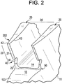
FIG. 2 is an enlarged perspective view of a radially inward region of the impeller ofFIG. 1 ; and -
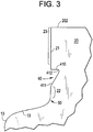
FIG. 3 is a side view of the radially inward region ofFIG. 2 . - The detailed description explains embodiments of the invention, together with advantages and features, by way of example with reference to the drawings.
- In accordance with aspects, thermal and mechanical stress interactions applied to a rotating component of a turbine engine are separated and total stresses on the component as well as various other components of the turbine engine are reduced significantly. This stress reduction is provided by a unique design, which may be implemented on new components and retrofit into existing fleets.
- With reference to
FIGS. 1-3 , arotating component 10 of a turbine engine is provided and, as shown inFIG. 1 , may be for example an impeller of a gas turbine engine although it is to be understood that this is merely exemplary and that other rotating components may be substituted to similar effect. Therotating component 10 includes awheel 11 and aforward section 12, which are each rotatable about a common rotational axis extending through thebore 13. Thebore 13 is defined at a radially central region of the rotatingcomponent 10 and extends axially through thewheel 11 and theforward section 12. - The
wheel 11 includes acurved surface 133 that is formed to be disposed about thebore 13. Thewheel 11 further includes anaft wheel face 14 extending radially outwardly from thecurved surface 133, aforward wheel face 15, which opposes theaft wheel face 14, and arim 16 at an outer radial diameter of theaft wheel face 14. A plurality of impeller vanes 20 protrudes axially from and may be arrayed circumferentially about theaft wheel face 14.Outer diameter portions 201 of the plurality ofimpeller vanes 20 are radially displaced from therim 16 to define acavity 17 at the outer radial diameter of theaft wheel face 14. - The plurality of impeller vanes 20 form a plurality of
grooves 30 between adjacent ones of the plurality ofimpeller vanes 20 that extend from thecavity 17 to a radially inward diameter of theaft wheel face 14. In accordance with embodiments, each of the plurality ofimpeller vanes 20 may have a substantially similar geometry and may spiral radially inwardly. During turbine operations, including transient turbine operations, fluids flow toward thecavity 17 and the plurality of circumferentially arrayedgrooves 30 direct this fluid flow to proceed from thecavity 17 to the radially inward diameter of theaft wheel face 14. - Each of the plurality of
impeller vanes 20 includes theouter diameter portion 201, aninner diameter portion 202, which may be narrower than theouter diameter portion 201, and, at theinner diameter portion 202, avane surface 21 that faces radially inwardly. Thevane surface 21 of at least one of the plurality of theimpeller vanes 20 is formed to define acutaway portion 40 between relatively shortaxial section 22 and relatively longaxial section 23 such that thecutaway portion 40 is defined axially proximate to theaft wheel face 14. With thecutaway portion 40 so defined, thermal responses and/or growth of the plurality ofimpeller vanes 20 are decoupled from the rotatingcomponent 10 thus reducing stress to avoid damage thereto. Hence, a lifetime of therotating component 10 may be extended. - As shown in
FIGS. 2 and3 , the respectiveinner diameter portions 202 of eachimpeller vane 20 are each radially proximate to thebore 13 and thecurved surface 133 such thatinterfaces 50 are formed between therespective vane surfaces 21 and thecurved surface 133. In accordance with embodiments, theinterfaces 50 may have a curvature that opposes that of thecurved surface 133. - As further shown in
FIGS. 2 and3 , therespective vane surfaces 21 of each of the plurality ofimpeller vanes 20 where thecutaway portion 40 is defined may include acircumferential surface 41 that forms a periphery of thecutaway portion 40 and extends betweendivergent sidewalls circumferential surface 41 is relatively flat in the circumferential direction and a plane thereof is substantially parallel with a plane of thecorresponding vane surface 21. - In accordance with embodiments, each of the
circumferential surfaces 41 may include afirst surface 410, asecond surface 411 and ashoulder surface 412 interposed between the first andsecond surfaces cutaway portions 40. Each of thefirst surfaces 410 may be leveled and each of thesecond surfaces 411 may be angled, closer to theaft wheel face 14 than thefirst surfaces 410 and longer than thefirst surfaces 410. Theshoulder surface 412 may be angular or curved. - In accordance with aspects, the
rotating component 10 as described above may be formed as a new feature whereby thecutaway portion 40 is either cast or machined into the at least one of the plurality of theimpeller vanes 20. Alternatively, the rotatingcomponent 10 can be formed in a retrofit, repair or refurbishing operation whereby thecutaway portion 40 is machined into the at least one of the plurality of theimpeller vanes 20. The machining in either case may be achieved by various processes including, but not limited to, electro-dynamic machining (EDM), milling or abrading. - While the invention has been described in detail in connection with only a limited number of embodiments, it should be readily understood that the invention is not limited to such disclosed embodiments. Rather, the invention can be modified to incorporate any number of variations, alterations, substitutions or equivalent arrangements not heretofore described, but which are commensurate with the spirit and scope of the invention. Additionally, while various embodiments of the invention have been described, it is to be understood that aspects of the invention may include only some of the described embodiments. Accordingly, the invention is not to be seen as limited by the foregoing description, but is only limited by the scope of the appended claims.
Claims (12)
- A rotating component (10) of a turbine engine, comprising:a wheel (11) having a face (14) to which fluid flow is provided; anda plurality of impeller vanes (20) forming a plurality of grooves (30) along which the fluid flow is directed from an outer to an inner diameter of the wheel face (14),at least one of the plurality of the impeller vanes (20) including a radially inwardly facing vane surface (21) formed to define a cutaway portion (40).
- The rotating component (10) according to claim 1, wherein the vane surface (21) comprises a relatively flat circumferential surface (41).
- The rotating component (10) according to claim 2, wherein the circumferential surface (41) comprises a first surface (410), a second surface (411) and a shoulder surface (412) interposed between the first and second surfaces.
- The rotating component (10) according to claim 3, wherein the first surface (410) is leveled and the second surface (411) is angled.
- The rotating component (10) according to claim 3 or 4, wherein the second surface (411) is longer and closer to the wheel face (14) than the first surface (410).
- The rotating component (10) according to any of claims 3 to 5, wherein the shoulder surface (412) is one of angular or curved.
- The rotating component (10) according to any of claims 1 to 6, wherein the cutaway portion (40) is axially proximate to the wheel face (14).
- The rotating component (10) any preceding claim:
wherein the wheel (11), is rotatable about a rotational axis,
the plurality of impeller vanes (20) protrude axially from the wheel face (14) to form the plurality of grooves (30) between adjacent ones of the plurality of impeller vanes (20), and
the at least one of the plurality of the impeller vanes (20) includes an inner diameter portion (202) at which the vane surface (21) faces radially inwardly. - The rotating component according to claim 8, wherein the wheel (11) is formed to define a bore (13) at a central region thereof and includes a curved surface (133) disposed about the bore (13).
- The rotating component according to claim 9, wherein the respective inner diameter portions (202) are proximate to the bore (13) to define curved interfaces (50) between the respective vane surfaces (21) and the curved surface (13).
- A method of forming a rotating component (10) of a turbine engine, comprising:fashioning a wheel (11) having a face (14) to which fluid flow is provided; andforming on the wheel face (14) a plurality of grooves (30) along which the secondary flow is directed from an outer to an inner diameter of the wheel face (14); andmachining a cutaway portion (40) at a radially inwardly facing vane surface (21) of at least one of the plurality of the impeller vanes.
- The method according to claim 11, wherein the machining comprises machining the cutaway portion (40) proximate to the wheel face (14).
Applications Claiming Priority (1)
| Application Number | Priority Date | Filing Date | Title |
|---|---|---|---|
| US13/020,584 US8556584B2 (en) | 2011-02-03 | 2011-02-03 | Rotating component of a turbine engine |
Publications (3)
| Publication Number | Publication Date |
|---|---|
| EP2484867A2 true EP2484867A2 (en) | 2012-08-08 |
| EP2484867A3 EP2484867A3 (en) | 2014-06-18 |
| EP2484867B1 EP2484867B1 (en) | 2020-01-15 |
Family
ID=45531797
Family Applications (1)
| Application Number | Title | Priority Date | Filing Date |
|---|---|---|---|
| EP12152941.6A Active EP2484867B1 (en) | 2011-02-03 | 2012-01-27 | Rotating component of a turbine engine |
Country Status (3)
| Country | Link |
|---|---|
| US (1) | US8556584B2 (en) |
| EP (1) | EP2484867B1 (en) |
| CN (1) | CN102628375B (en) |
Cited By (1)
| Publication number | Priority date | Publication date | Assignee | Title |
|---|---|---|---|---|
| EP2612989A3 (en) * | 2012-01-05 | 2014-06-18 | General Electric Company | System and method for reducing stress in a rotor |
Families Citing this family (11)
| Publication number | Priority date | Publication date | Assignee | Title |
|---|---|---|---|---|
| US8348599B2 (en) * | 2010-03-26 | 2013-01-08 | General Electric Company | Turbine rotor wheel |
| US9188010B2 (en) * | 2012-06-25 | 2015-11-17 | General Electric Company | Systems and methods to control flow in a rotor wheel |
| US9651057B2 (en) | 2013-12-19 | 2017-05-16 | Regal Beloit America, Inc. | Blower assembly including a noise attenuating impeller and method for assembling the same |
| AT515236B1 (en) * | 2013-12-23 | 2015-12-15 | Fronius Int Gmbh | Welding wire feed roller and feed device for conveying a welding wire |
| US9657746B2 (en) | 2014-08-29 | 2017-05-23 | Pratt & Whitney Canada Corp. | Compressor rotor with anti-vortex fins |
| US9803480B2 (en) | 2014-12-19 | 2017-10-31 | General Electric Company | Liquid ring turbine and method of use |
| PL415045A1 (en) | 2015-12-03 | 2017-06-05 | General Electric Company | Turbine disk and methods for manufacturing them |
| US10208764B2 (en) * | 2016-02-25 | 2019-02-19 | General Electric Company | Rotor wheel and impeller inserts |
| KR102048874B1 (en) * | 2018-04-09 | 2019-11-26 | 두산중공업 주식회사 | Turbine vane having improved flexibility |
| US20210115796A1 (en) * | 2019-10-18 | 2021-04-22 | United Technologies Corporation | Airfoil component with trailing end margin and cutback |
| US11761632B2 (en) | 2021-08-05 | 2023-09-19 | General Electric Company | Combustor swirler with vanes incorporating open area |
Family Cites Families (25)
| Publication number | Priority date | Publication date | Assignee | Title |
|---|---|---|---|---|
| GB586836A (en) * | 1943-05-04 | 1947-04-02 | Turbo Engineering Corp | Elastic fluid pumps and turbines |
| US3647313A (en) * | 1970-06-01 | 1972-03-07 | Gen Electric | Gas turbine engines with compressor rotor cooling |
| JPS5115210A (en) * | 1974-07-02 | 1976-02-06 | Rotoron Inc | Zatsuongenshono fuan |
| JPS61109608A (en) * | 1984-11-01 | 1986-05-28 | Mitsubishi Heavy Ind Ltd | Method of machining impeller |
| KR930021927A (en) * | 1992-04-23 | 1993-11-23 | 조운 이 페더리시 | Impeller blades affected by reduced stress |
| JP3192854B2 (en) * | 1993-12-28 | 2001-07-30 | 株式会社東芝 | Turbine cooling blade |
| US5511946A (en) * | 1994-12-08 | 1996-04-30 | General Electric Company | Cooled airfoil tip corner |
| US5997244A (en) * | 1997-05-16 | 1999-12-07 | Alliedsignal Inc. | Cooling airflow vortex spoiler |
| US6128820A (en) * | 1998-10-20 | 2000-10-10 | General Electric Co. | Method of repairing damaged turbine rotor wheels using differentially controlled temperatures |
| US6210116B1 (en) * | 1998-11-05 | 2001-04-03 | John E. Kuczaj | High efficiency pump impeller |
| US6361277B1 (en) * | 2000-01-24 | 2002-03-26 | General Electric Company | Methods and apparatus for directing airflow to a compressor bore |
| US6622724B1 (en) * | 2000-06-19 | 2003-09-23 | Respironics, Inc. | Impeller and a pressure support system and method using such an impeller |
| US6537030B1 (en) * | 2000-10-18 | 2003-03-25 | Fasco Industries, Inc. | Single piece impeller having radial output |
| US6733240B2 (en) * | 2001-07-18 | 2004-05-11 | General Electric Company | Serrated fan blade |
| EP1338793A3 (en) * | 2002-02-22 | 2010-09-01 | Mitsubishi Heavy Industries, Ltd. | Serrated wind turbine blade trailing edge |
| US6881033B2 (en) * | 2002-09-30 | 2005-04-19 | Fisher & Paykel Healthcare Limited | Impeller |
| DE50306044D1 (en) * | 2003-09-05 | 2007-02-01 | Siemens Ag | Shovel of a turbine |
| US7255530B2 (en) * | 2003-12-12 | 2007-08-14 | Honeywell International Inc. | Vane and throat shaping |
| US7632073B2 (en) * | 2005-06-08 | 2009-12-15 | Dresser-Rand Company | Impeller with machining access panel |
| JP3953085B1 (en) * | 2006-03-08 | 2007-08-01 | ダイキン工業株式会社 | Centrifugal blower impeller blade, blade support rotating body, centrifugal blower impeller, and method for manufacturing centrifugal blower impeller |
| US20070269316A1 (en) * | 2006-05-18 | 2007-11-22 | Williams Andrew D | Turbine blade with trailing edge cutback and method of making same |
| US20080229742A1 (en) * | 2007-03-21 | 2008-09-25 | Philippe Renaud | Extended Leading-Edge Compressor Wheel |
| EP2031243A1 (en) * | 2007-08-31 | 2009-03-04 | Lm Glasfiber A/S | Means to maintain a flow attached to the exterior of a flow control member |
| US8047768B2 (en) * | 2009-01-12 | 2011-11-01 | General Electric Company | Split impeller configuration for synchronizing thermal response between turbine wheels |
| US9145771B2 (en) * | 2010-07-28 | 2015-09-29 | United Technologies Corporation | Rotor assembly disk spacer for a gas turbine engine |
-
2011
- 2011-02-03 US US13/020,584 patent/US8556584B2/en active Active
-
2012
- 2012-01-27 EP EP12152941.6A patent/EP2484867B1/en active Active
- 2012-02-02 CN CN201210029301.8A patent/CN102628375B/en active Active
Non-Patent Citations (1)
| Title |
|---|
| None |
Cited By (1)
| Publication number | Priority date | Publication date | Assignee | Title |
|---|---|---|---|---|
| EP2612989A3 (en) * | 2012-01-05 | 2014-06-18 | General Electric Company | System and method for reducing stress in a rotor |
Also Published As
| Publication number | Publication date |
|---|---|
| EP2484867B1 (en) | 2020-01-15 |
| EP2484867A3 (en) | 2014-06-18 |
| CN102628375A (en) | 2012-08-08 |
| CN102628375B (en) | 2016-01-27 |
| US20120201669A1 (en) | 2012-08-09 |
| US8556584B2 (en) | 2013-10-15 |
Similar Documents
| Publication | Publication Date | Title |
|---|---|---|
| US8556584B2 (en) | Rotating component of a turbine engine | |
| US8403645B2 (en) | Turbofan flow path trenches | |
| EP2565380B1 (en) | Hole liners for repair of variable vane shroud counterbore holes | |
| EP2586992B1 (en) | Rotating vane seal with cooling air passages | |
| US9394915B2 (en) | Seal land for static structure of a gas turbine engine | |
| US9874101B2 (en) | Platform with curved edges | |
| JP2012026448A (en) | Components with bonded edges | |
| RU2568353C2 (en) | Stator of axial turbine machine , method of its manufacturing and turbine machine containing this stator | |
| EP3139001B1 (en) | Damper pin for turbine blades and corresponding turbine engine | |
| US8113784B2 (en) | Coolable airfoil attachment section | |
| US8925201B2 (en) | Method and apparatus for providing rotor discs | |
| US20190128126A1 (en) | Turbine blisk and method of manufacturing thereof | |
| US20150098802A1 (en) | Shrouded turbine blisk and method of manufacturing same | |
| EP4130430A1 (en) | Integrated bladed rotor | |
| US20190136700A1 (en) | Ceramic matrix composite tip shroud assembly for gas turbines | |
| US10392966B2 (en) | Retaining ring end gap features | |
| US9739159B2 (en) | Method and system for relieving turbine rotor blade dovetail stress | |
| US10544687B2 (en) | Shrouded blade of a gas turbine engine | |
| US10174623B2 (en) | Rotary blade manufacturing method | |
| US20200353577A1 (en) | Turbine wheels, turbine engines including the same, and methods of fabricating turbine wheels with improved bond line geometry | |
| EP2434099B1 (en) | Blade for a gas turbine engine | |
| EP2933437B1 (en) | Systems and methods for anti-rotation features | |
| US10787916B2 (en) | Turbine wheel assembly with ceramic matrix composite components | |
| US11326462B2 (en) | Gas turbine and spacer disk for gas turbine |
Legal Events
| Date | Code | Title | Description |
|---|---|---|---|
| PUAI | Public reference made under article 153(3) epc to a published international application that has entered the european phase |
Free format text: ORIGINAL CODE: 0009012 |
|
| AK | Designated contracting states |
Kind code of ref document: A2 Designated state(s): AL AT BE BG CH CY CZ DE DK EE ES FI FR GB GR HR HU IE IS IT LI LT LU LV MC MK MT NL NO PL PT RO RS SE SI SK SM TR |
|
| AX | Request for extension of the european patent |
Extension state: BA ME |
|
| PUAL | Search report despatched |
Free format text: ORIGINAL CODE: 0009013 |
|
| AK | Designated contracting states |
Kind code of ref document: A3 Designated state(s): AL AT BE BG CH CY CZ DE DK EE ES FI FR GB GR HR HU IE IS IT LI LT LU LV MC MK MT NL NO PL PT RO RS SE SI SK SM TR |
|
| AX | Request for extension of the european patent |
Extension state: BA ME |
|
| RIC1 | Information provided on ipc code assigned before grant |
Ipc: F01D 5/14 20060101ALI20140512BHEP Ipc: F01D 5/03 20060101AFI20140512BHEP Ipc: F01D 5/08 20060101ALI20140512BHEP |
|
| 17P | Request for examination filed |
Effective date: 20141218 |
|
| RBV | Designated contracting states (corrected) |
Designated state(s): AL AT BE BG CH CY CZ DE DK EE ES FI FR GB GR HR HU IE IS IT LI LT LU LV MC MK MT NL NO PL PT RO RS SE SI SK SM TR |
|
| GRAP | Despatch of communication of intention to grant a patent |
Free format text: ORIGINAL CODE: EPIDOSNIGR1 |
|
| STAA | Information on the status of an ep patent application or granted ep patent |
Free format text: STATUS: GRANT OF PATENT IS INTENDED |
|
| INTG | Intention to grant announced |
Effective date: 20190801 |
|
| GRAS | Grant fee paid |
Free format text: ORIGINAL CODE: EPIDOSNIGR3 |
|
| GRAA | (expected) grant |
Free format text: ORIGINAL CODE: 0009210 |
|
| STAA | Information on the status of an ep patent application or granted ep patent |
Free format text: STATUS: THE PATENT HAS BEEN GRANTED |
|
| AK | Designated contracting states |
Kind code of ref document: B1 Designated state(s): AL AT BE BG CH CY CZ DE DK EE ES FI FR GB GR HR HU IE IS IT LI LT LU LV MC MK MT NL NO PL PT RO RS SE SI SK SM TR |
|
| REG | Reference to a national code |
Ref country code: GB Ref legal event code: FG4D Ref country code: CH Ref legal event code: EP |
|
| REG | Reference to a national code |
Ref country code: IE Ref legal event code: FG4D |
|
| REG | Reference to a national code |
Ref country code: DE Ref legal event code: R096 Ref document number: 602012067224 Country of ref document: DE |
|
| REG | Reference to a national code |
Ref country code: AT Ref legal event code: REF Ref document number: 1225310 Country of ref document: AT Kind code of ref document: T Effective date: 20200215 |
|
| REG | Reference to a national code |
Ref country code: NL Ref legal event code: MP Effective date: 20200115 |
|
| REG | Reference to a national code |
Ref country code: LT Ref legal event code: MG4D |
|
| PG25 | Lapsed in a contracting state [announced via postgrant information from national office to epo] |
Ref country code: FI Free format text: LAPSE BECAUSE OF FAILURE TO SUBMIT A TRANSLATION OF THE DESCRIPTION OR TO PAY THE FEE WITHIN THE PRESCRIBED TIME-LIMIT Effective date: 20200115 Ref country code: NO Free format text: LAPSE BECAUSE OF FAILURE TO SUBMIT A TRANSLATION OF THE DESCRIPTION OR TO PAY THE FEE WITHIN THE PRESCRIBED TIME-LIMIT Effective date: 20200415 Ref country code: NL Free format text: LAPSE BECAUSE OF FAILURE TO SUBMIT A TRANSLATION OF THE DESCRIPTION OR TO PAY THE FEE WITHIN THE PRESCRIBED TIME-LIMIT Effective date: 20200115 Ref country code: RS Free format text: LAPSE BECAUSE OF FAILURE TO SUBMIT A TRANSLATION OF THE DESCRIPTION OR TO PAY THE FEE WITHIN THE PRESCRIBED TIME-LIMIT Effective date: 20200115 Ref country code: PT Free format text: LAPSE BECAUSE OF FAILURE TO SUBMIT A TRANSLATION OF THE DESCRIPTION OR TO PAY THE FEE WITHIN THE PRESCRIBED TIME-LIMIT Effective date: 20200607 |
|
| PG25 | Lapsed in a contracting state [announced via postgrant information from national office to epo] |
Ref country code: SE Free format text: LAPSE BECAUSE OF FAILURE TO SUBMIT A TRANSLATION OF THE DESCRIPTION OR TO PAY THE FEE WITHIN THE PRESCRIBED TIME-LIMIT Effective date: 20200115 Ref country code: IS Free format text: LAPSE BECAUSE OF FAILURE TO SUBMIT A TRANSLATION OF THE DESCRIPTION OR TO PAY THE FEE WITHIN THE PRESCRIBED TIME-LIMIT Effective date: 20200515 Ref country code: GR Free format text: LAPSE BECAUSE OF FAILURE TO SUBMIT A TRANSLATION OF THE DESCRIPTION OR TO PAY THE FEE WITHIN THE PRESCRIBED TIME-LIMIT Effective date: 20200416 Ref country code: HR Free format text: LAPSE BECAUSE OF FAILURE TO SUBMIT A TRANSLATION OF THE DESCRIPTION OR TO PAY THE FEE WITHIN THE PRESCRIBED TIME-LIMIT Effective date: 20200115 Ref country code: LV Free format text: LAPSE BECAUSE OF FAILURE TO SUBMIT A TRANSLATION OF THE DESCRIPTION OR TO PAY THE FEE WITHIN THE PRESCRIBED TIME-LIMIT Effective date: 20200115 Ref country code: BG Free format text: LAPSE BECAUSE OF FAILURE TO SUBMIT A TRANSLATION OF THE DESCRIPTION OR TO PAY THE FEE WITHIN THE PRESCRIBED TIME-LIMIT Effective date: 20200415 |
|
| REG | Reference to a national code |
Ref country code: CH Ref legal event code: PL |
|
| REG | Reference to a national code |
Ref country code: BE Ref legal event code: MM Effective date: 20200131 |
|
| REG | Reference to a national code |
Ref country code: DE Ref legal event code: R097 Ref document number: 602012067224 Country of ref document: DE |
|
| PG25 | Lapsed in a contracting state [announced via postgrant information from national office to epo] |
Ref country code: LT Free format text: LAPSE BECAUSE OF FAILURE TO SUBMIT A TRANSLATION OF THE DESCRIPTION OR TO PAY THE FEE WITHIN THE PRESCRIBED TIME-LIMIT Effective date: 20200115 Ref country code: CZ Free format text: LAPSE BECAUSE OF FAILURE TO SUBMIT A TRANSLATION OF THE DESCRIPTION OR TO PAY THE FEE WITHIN THE PRESCRIBED TIME-LIMIT Effective date: 20200115 Ref country code: RO Free format text: LAPSE BECAUSE OF FAILURE TO SUBMIT A TRANSLATION OF THE DESCRIPTION OR TO PAY THE FEE WITHIN THE PRESCRIBED TIME-LIMIT Effective date: 20200115 Ref country code: SK Free format text: LAPSE BECAUSE OF FAILURE TO SUBMIT A TRANSLATION OF THE DESCRIPTION OR TO PAY THE FEE WITHIN THE PRESCRIBED TIME-LIMIT Effective date: 20200115 Ref country code: LU Free format text: LAPSE BECAUSE OF NON-PAYMENT OF DUE FEES Effective date: 20200127 Ref country code: SM Free format text: LAPSE BECAUSE OF FAILURE TO SUBMIT A TRANSLATION OF THE DESCRIPTION OR TO PAY THE FEE WITHIN THE PRESCRIBED TIME-LIMIT Effective date: 20200115 Ref country code: DK Free format text: LAPSE BECAUSE OF FAILURE TO SUBMIT A TRANSLATION OF THE DESCRIPTION OR TO PAY THE FEE WITHIN THE PRESCRIBED TIME-LIMIT Effective date: 20200115 Ref country code: EE Free format text: LAPSE BECAUSE OF FAILURE TO SUBMIT A TRANSLATION OF THE DESCRIPTION OR TO PAY THE FEE WITHIN THE PRESCRIBED TIME-LIMIT Effective date: 20200115 Ref country code: MC Free format text: LAPSE BECAUSE OF FAILURE TO SUBMIT A TRANSLATION OF THE DESCRIPTION OR TO PAY THE FEE WITHIN THE PRESCRIBED TIME-LIMIT Effective date: 20200115 Ref country code: ES Free format text: LAPSE BECAUSE OF FAILURE TO SUBMIT A TRANSLATION OF THE DESCRIPTION OR TO PAY THE FEE WITHIN THE PRESCRIBED TIME-LIMIT Effective date: 20200115 |
|
| REG | Reference to a national code |
Ref country code: AT Ref legal event code: MK05 Ref document number: 1225310 Country of ref document: AT Kind code of ref document: T Effective date: 20200115 |
|
| PLBE | No opposition filed within time limit |
Free format text: ORIGINAL CODE: 0009261 |
|
| STAA | Information on the status of an ep patent application or granted ep patent |
Free format text: STATUS: NO OPPOSITION FILED WITHIN TIME LIMIT |
|
| PG25 | Lapsed in a contracting state [announced via postgrant information from national office to epo] |
Ref country code: BE Free format text: LAPSE BECAUSE OF NON-PAYMENT OF DUE FEES Effective date: 20200131 Ref country code: LI Free format text: LAPSE BECAUSE OF NON-PAYMENT OF DUE FEES Effective date: 20200131 Ref country code: CH Free format text: LAPSE BECAUSE OF NON-PAYMENT OF DUE FEES Effective date: 20200131 |
|
| 26N | No opposition filed |
Effective date: 20201016 |
|
| PG25 | Lapsed in a contracting state [announced via postgrant information from national office to epo] |
Ref country code: IE Free format text: LAPSE BECAUSE OF NON-PAYMENT OF DUE FEES Effective date: 20200127 Ref country code: AT Free format text: LAPSE BECAUSE OF FAILURE TO SUBMIT A TRANSLATION OF THE DESCRIPTION OR TO PAY THE FEE WITHIN THE PRESCRIBED TIME-LIMIT Effective date: 20200115 Ref country code: IT Free format text: LAPSE BECAUSE OF FAILURE TO SUBMIT A TRANSLATION OF THE DESCRIPTION OR TO PAY THE FEE WITHIN THE PRESCRIBED TIME-LIMIT Effective date: 20200115 |
|
| PG25 | Lapsed in a contracting state [announced via postgrant information from national office to epo] |
Ref country code: SI Free format text: LAPSE BECAUSE OF FAILURE TO SUBMIT A TRANSLATION OF THE DESCRIPTION OR TO PAY THE FEE WITHIN THE PRESCRIBED TIME-LIMIT Effective date: 20200115 Ref country code: PL Free format text: LAPSE BECAUSE OF FAILURE TO SUBMIT A TRANSLATION OF THE DESCRIPTION OR TO PAY THE FEE WITHIN THE PRESCRIBED TIME-LIMIT Effective date: 20200115 |
|
| PG25 | Lapsed in a contracting state [announced via postgrant information from national office to epo] |
Ref country code: TR Free format text: LAPSE BECAUSE OF FAILURE TO SUBMIT A TRANSLATION OF THE DESCRIPTION OR TO PAY THE FEE WITHIN THE PRESCRIBED TIME-LIMIT Effective date: 20200115 Ref country code: MT Free format text: LAPSE BECAUSE OF FAILURE TO SUBMIT A TRANSLATION OF THE DESCRIPTION OR TO PAY THE FEE WITHIN THE PRESCRIBED TIME-LIMIT Effective date: 20200115 Ref country code: CY Free format text: LAPSE BECAUSE OF FAILURE TO SUBMIT A TRANSLATION OF THE DESCRIPTION OR TO PAY THE FEE WITHIN THE PRESCRIBED TIME-LIMIT Effective date: 20200115 |
|
| PG25 | Lapsed in a contracting state [announced via postgrant information from national office to epo] |
Ref country code: MK Free format text: LAPSE BECAUSE OF FAILURE TO SUBMIT A TRANSLATION OF THE DESCRIPTION OR TO PAY THE FEE WITHIN THE PRESCRIBED TIME-LIMIT Effective date: 20200115 Ref country code: AL Free format text: LAPSE BECAUSE OF FAILURE TO SUBMIT A TRANSLATION OF THE DESCRIPTION OR TO PAY THE FEE WITHIN THE PRESCRIBED TIME-LIMIT Effective date: 20200115 |
|
| P01 | Opt-out of the competence of the unified patent court (upc) registered |
Effective date: 20230522 |
|
| REG | Reference to a national code |
Ref country code: DE Ref legal event code: R082 Ref document number: 602012067224 Country of ref document: DE Ref country code: DE Ref legal event code: R081 Ref document number: 602012067224 Country of ref document: DE Owner name: GENERAL ELECTRIC TECHNOLOGY GMBH, CH Free format text: FORMER OWNER: GENERAL ELECTRIC COMPANY, SCHENECTADY, NY, US |
|
| REG | Reference to a national code |
Ref country code: GB Ref legal event code: 732E Free format text: REGISTERED BETWEEN 20240222 AND 20240228 |
|
| PGFP | Annual fee paid to national office [announced via postgrant information from national office to epo] |
Ref country code: GB Payment date: 20251220 Year of fee payment: 15 |
|
| PGFP | Annual fee paid to national office [announced via postgrant information from national office to epo] |
Ref country code: FR Payment date: 20251218 Year of fee payment: 15 |
|
| PGFP | Annual fee paid to national office [announced via postgrant information from national office to epo] |
Ref country code: DE Payment date: 20251217 Year of fee payment: 15 |