EP2484866A2 - Cross-over purge flow system for a turbomachine wheel member - Google Patents
Cross-over purge flow system for a turbomachine wheel member Download PDFInfo
- Publication number
- EP2484866A2 EP2484866A2 EP12153161A EP12153161A EP2484866A2 EP 2484866 A2 EP2484866 A2 EP 2484866A2 EP 12153161 A EP12153161 A EP 12153161A EP 12153161 A EP12153161 A EP 12153161A EP 2484866 A2 EP2484866 A2 EP 2484866A2
- Authority
- EP
- European Patent Office
- Prior art keywords
- purge
- wheel member
- circuits
- purge flow
- flow
- Prior art date
- Legal status (The legal status is an assumption and is not a legal conclusion. Google has not performed a legal analysis and makes no representation as to the accuracy of the status listed.)
- Granted
Links
Images


Classifications
-
- F—MECHANICAL ENGINEERING; LIGHTING; HEATING; WEAPONS; BLASTING
- F01—MACHINES OR ENGINES IN GENERAL; ENGINE PLANTS IN GENERAL; STEAM ENGINES
- F01D—NON-POSITIVE DISPLACEMENT MACHINES OR ENGINES, e.g. STEAM TURBINES
- F01D5/00—Blades; Blade-carrying members; Heating, heat-insulating, cooling or antivibration means on the blades or the members
- F01D5/02—Blade-carrying members, e.g. rotors
- F01D5/08—Heating, heat-insulating or cooling means
-
- F—MECHANICAL ENGINEERING; LIGHTING; HEATING; WEAPONS; BLASTING
- F01—MACHINES OR ENGINES IN GENERAL; ENGINE PLANTS IN GENERAL; STEAM ENGINES
- F01D—NON-POSITIVE DISPLACEMENT MACHINES OR ENGINES, e.g. STEAM TURBINES
- F01D25/00—Component parts, details, or accessories, not provided for in, or of interest apart from, other groups
- F01D25/08—Cooling; Heating; Heat-insulation
-
- F—MECHANICAL ENGINEERING; LIGHTING; HEATING; WEAPONS; BLASTING
- F01—MACHINES OR ENGINES IN GENERAL; ENGINE PLANTS IN GENERAL; STEAM ENGINES
- F01D—NON-POSITIVE DISPLACEMENT MACHINES OR ENGINES, e.g. STEAM TURBINES
- F01D25/00—Component parts, details, or accessories, not provided for in, or of interest apart from, other groups
- F01D25/08—Cooling; Heating; Heat-insulation
- F01D25/12—Cooling
-
- F—MECHANICAL ENGINEERING; LIGHTING; HEATING; WEAPONS; BLASTING
- F01—MACHINES OR ENGINES IN GENERAL; ENGINE PLANTS IN GENERAL; STEAM ENGINES
- F01D—NON-POSITIVE DISPLACEMENT MACHINES OR ENGINES, e.g. STEAM TURBINES
- F01D5/00—Blades; Blade-carrying members; Heating, heat-insulating, cooling or antivibration means on the blades or the members
- F01D5/02—Blade-carrying members, e.g. rotors
- F01D5/022—Blade-carrying members, e.g. rotors with concentric rows of axial blades
-
- F—MECHANICAL ENGINEERING; LIGHTING; HEATING; WEAPONS; BLASTING
- F01—MACHINES OR ENGINES IN GENERAL; ENGINE PLANTS IN GENERAL; STEAM ENGINES
- F01D—NON-POSITIVE DISPLACEMENT MACHINES OR ENGINES, e.g. STEAM TURBINES
- F01D5/00—Blades; Blade-carrying members; Heating, heat-insulating, cooling or antivibration means on the blades or the members
- F01D5/02—Blade-carrying members, e.g. rotors
- F01D5/06—Rotors for more than one axial stage, e.g. of drum or multiple disc type; Details thereof, e.g. shafts, shaft connections
-
- F—MECHANICAL ENGINEERING; LIGHTING; HEATING; WEAPONS; BLASTING
- F01—MACHINES OR ENGINES IN GENERAL; ENGINE PLANTS IN GENERAL; STEAM ENGINES
- F01D—NON-POSITIVE DISPLACEMENT MACHINES OR ENGINES, e.g. STEAM TURBINES
- F01D5/00—Blades; Blade-carrying members; Heating, heat-insulating, cooling or antivibration means on the blades or the members
- F01D5/02—Blade-carrying members, e.g. rotors
- F01D5/08—Heating, heat-insulating or cooling means
- F01D5/081—Cooling fluid being directed on the side of the rotor disc or at the roots of the blades
- F01D5/082—Cooling fluid being directed on the side of the rotor disc or at the roots of the blades on the side of the rotor disc
-
- F—MECHANICAL ENGINEERING; LIGHTING; HEATING; WEAPONS; BLASTING
- F01—MACHINES OR ENGINES IN GENERAL; ENGINE PLANTS IN GENERAL; STEAM ENGINES
- F01D—NON-POSITIVE DISPLACEMENT MACHINES OR ENGINES, e.g. STEAM TURBINES
- F01D5/00—Blades; Blade-carrying members; Heating, heat-insulating, cooling or antivibration means on the blades or the members
- F01D5/02—Blade-carrying members, e.g. rotors
- F01D5/08—Heating, heat-insulating or cooling means
- F01D5/085—Heating, heat-insulating or cooling means cooling fluid circulating inside the rotor
-
- F—MECHANICAL ENGINEERING; LIGHTING; HEATING; WEAPONS; BLASTING
- F01—MACHINES OR ENGINES IN GENERAL; ENGINE PLANTS IN GENERAL; STEAM ENGINES
- F01D—NON-POSITIVE DISPLACEMENT MACHINES OR ENGINES, e.g. STEAM TURBINES
- F01D5/00—Blades; Blade-carrying members; Heating, heat-insulating, cooling or antivibration means on the blades or the members
- F01D5/02—Blade-carrying members, e.g. rotors
- F01D5/08—Heating, heat-insulating or cooling means
- F01D5/085—Heating, heat-insulating or cooling means cooling fluid circulating inside the rotor
- F01D5/087—Heating, heat-insulating or cooling means cooling fluid circulating inside the rotor in the radial passages of the rotor disc
Definitions
- the subject matter disclosed herein relates to the art of turbomachines and, more particularly, to a cross-over purge flow system for a turbomachine wheel member.
- Gas turbomachines include internal and rotating, components that may be subjected to high temperatures.
- rotor components are subjected to high temperatures and temperature gradients that lead to low cycle fatigue, embrittlement, and creep, all of which have a detrimental effect on system performance and durability.
- turbomachines include purge systems that direct cooling air flows onto various components.
- Existing purge systems rely on a single stage pressure drop to drive air flow around wheel surfaces. A purge air flow starts at a region of higher pressure in the flowpath, travels inward toward a wheel bore region, and back to a region of lower pressure in the flowpath. In this manner, the purge air flow reduces temperature gradients as well as lowers peak rotor wheel temperature to enhance component life and turbomachine operability.
- the invention resides in a wheel member including a body having a first surface that extends to a second surface through an intermediate portion.
- the body includes an outer diametric surface and a central bore.
- a first plurality of purge circuits are formed in the body.
- the first plurality of purge circuits extend from a first end to a second end through the body.
- the first plurality of purge circuits are arranged to direct a first purge flow in a first direction.
- a second plurality of purge circuits are also formed in the body and are fluidly isolated from the first plurality of purge circuits.
- the second plurality of purge circuits extend from a first end portion to a second end portion through the body and are arranged to direct a second purge flow in a second direction, that is distinct from the first direction, to establish a cross-over purge flow.
- the invention resides in a turbomachine including a compressor portion, and a turbine portion operatively connected to the compressor portion.
- At least one of the compressor portion and turbine portion includes a wheel member that includes a body having a first surface that extends to a second surface through an intermediate portion.
- the body includes an outer diametric surface and a central bore.
- a first plurality of purge circuits are formed in the body.
- the first plurality of purge circuits extend from a first end to a second end through the body.
- the first plurality of purge circuits are arranged to direct a first purge flow in a first direction.
- a second plurality of purge circuits are also formed in the body and are fluidly isolated from the first plurality of purge circuits.
- the second plurality of purge circuits extend from a first end portion to a second end portion through the body and are arranged to direct a second purge flow in a second direction, that is distinct from the first direction, to establish a cross-over purge flow
- the invention resides in a method of delivering a cross-over purge flow in a turbomachine includes passing a first purge flow from a flowpath of the turbomachine toward a wheel member, passing a second purge flow from a wheel space of the turbomachine along the wheel member, guiding the first purge flow through a first purge flow circuit formed in the wheel member, guiding the second purge flow through a second purge flow circuit, fluidly isolated from the first purge circuit, formed in the wheel member, discharging the first purge flow from the first purge flow circuit toward a central bore of the wheel member, and discharging the second purge flow from the second purge flow circuit toward the flowpath to establish a cross-over purge flow at the wheel member.
- Turbomachine 2 includes a housing 4 that surrounds a compressor portion 6 operatively connected to a turbine portion 8.
- Compressor portion 6 includes a plurality of rotor or wheel members, three of which are indicated at 20-22. Each wheel member 20-22 is operatively connected to corresponding pluralities of vanes or blades 23-25 that establish various stages of compressor portion 6.
- turbine portion 8 includes a plurality of rotor or wheel members, three of which are indicated at 26-28. Each wheel member 26-28 is operatively connected to corresponding pluralities of vanes or blades 31-33 that establish various stages of turbine section 8.
- compressor flow 40 includes purge flows that are diverted into wheel members 20-22 to provide desired air flow.
- wheel member 21 includes a cross-over purge flow arrangement 45.
- wheel member 21 includes a body 50 having a first surface 54 that extends to an opposing second surface 55 through an intermediate portion 56.
- Wheel member 21 includes an outer diametric surface 58 and a central bore 60.
- a blade mounting member 62 is provided on outer diametric surface 58.
- Blade mounting member 62 provides an interface between the plurality of blades 24 and wheel member 21.
- wheel member 21 includes a first plurality of purge circuits 64 and a second plurality of purge circuits 68 arranged in body 50 adjacent outer diametric surface 58.
- First and second plurality of purge circuits 64 and 68 alternate around a circumference of body 50 and are separated by a plurality of bolt passages 70.
- each of the first plurality of purge circuits 64 extend about a first circumference of wheel member 21 and include a conduit 72 having a first end 74, exposed at second surface 55, that extends through body 50 to a second end 75 that is exposed at first surface 54.
- First end 74 included an inlet channel 77 that extends from conduit 72 towards outer diametric surface 58.
- Second end 75 includes an outlet channel 79 that extends from conduit 72 towards central bore 60.
- each of the second plurality of purge circuits 68 extend along a second circumference of wheel member 21 and include a conduit 83 having a first end portion 85, exposed at second surface 55, that extends through body 50 to a second end portion 86 exposed at first surface 54.
- the first circumference is substantially similar to the second circumference.
- the first and second circumferences are arranged adjacent outer diametric surface 58.
- First end portion 85 includes an inlet passage 88 that extends from conduit 83 toward central bore 60.
- Second end portion 86 includes an outlet passage 90 that extends from conduit 83 toward outer diametric surface 58.
- a second purge flow 95 of compressor flow 40 passes from a central bore (not separately labeled) of wheel member 22, along second surface 55 toward inlet passage 88.
- Second purge flow 95 of compressor flow 40 enters conduit 83, flows toward second end portion 86, and exits through outlet passage 90 toward outer diametric surface 58 forming a cross-over purge flow zone 100 such as shown in FIG. 7 .
- the exemplary embodiments enable a single rotating component to carry two or more fully independent cooling circuits.
- the particular arrangement allows for higher purge flows as a result of increased pressure drops of the purge flow passing through the wheel member.
- the placement of the purge passage in relation to the bolt passages creates a key feature that simplifies construction. That is, the purge passages are independent of an orientation and/or alignment of the bolt passages on adjacent wheels.
- the first and second pluralities of purge circuits could be arranged at different radial distances from the central bore.
- the first and second pluralities of purge circuits could be provided on other ones of the wheel members in the compressor portion, or on wheel members in the turbine portion.
Landscapes
- Engineering & Computer Science (AREA)
- Mechanical Engineering (AREA)
- General Engineering & Computer Science (AREA)
- Structures Of Non-Positive Displacement Pumps (AREA)
Abstract
Description
- The subject matter disclosed herein relates to the art of turbomachines and, more particularly, to a cross-over purge flow system for a turbomachine wheel member.
- Gas turbomachines include internal and rotating, components that may be subjected to high temperatures. In a compressor, rotor components are subjected to high temperatures and temperature gradients that lead to low cycle fatigue, embrittlement, and creep, all of which have a detrimental effect on system performance and durability. In order to enhance system performance and extend component life, turbomachines include purge systems that direct cooling air flows onto various components. Existing purge systems rely on a single stage pressure drop to drive air flow around wheel surfaces. A purge air flow starts at a region of higher pressure in the flowpath, travels inward toward a wheel bore region, and back to a region of lower pressure in the flowpath. In this manner, the purge air flow reduces temperature gradients as well as lowers peak rotor wheel temperature to enhance component life and turbomachine operability.
- According to a first aspect, the invention resides in a wheel member including a body having a first surface that extends to a second surface through an intermediate portion. The body includes an outer diametric surface and a central bore. A first plurality of purge circuits are formed in the body. The first plurality of purge circuits extend from a first end to a second end through the body. The first plurality of purge circuits are arranged to direct a first purge flow in a first direction. A second plurality of purge circuits are also formed in the body and are fluidly isolated from the first plurality of purge circuits. The second plurality of purge circuits extend from a first end portion to a second end portion through the body and are arranged to direct a second purge flow in a second direction, that is distinct from the first direction, to establish a cross-over purge flow.
- According to another aspect, the invention resides in a turbomachine including a compressor portion, and a turbine portion operatively connected to the compressor portion. At least one of the compressor portion and turbine portion includes a wheel member that includes a body having a first surface that extends to a second surface through an intermediate portion. The body includes an outer diametric surface and a central bore. A first plurality of purge circuits are formed in the body. The first plurality of purge circuits extend from a first end to a second end through the body. The first plurality of purge circuits are arranged to direct a first purge flow in a first direction. A second plurality of purge circuits are also formed in the body and are fluidly isolated from the first plurality of purge circuits. The second plurality of purge circuits extend from a first end portion to a second end portion through the body and are arranged to direct a second purge flow in a second direction, that is distinct from the first direction, to establish a cross-over purge flow.
- According to yet another aspect, the invention resides in a method of delivering a cross-over purge flow in a turbomachine includes passing a first purge flow from a flowpath of the turbomachine toward a wheel member, passing a second purge flow from a wheel space of the turbomachine along the wheel member, guiding the first purge flow through a first purge flow circuit formed in the wheel member, guiding the second purge flow through a second purge flow circuit, fluidly isolated from the first purge circuit, formed in the wheel member, discharging the first purge flow from the first purge flow circuit toward a central bore of the wheel member, and discharging the second purge flow from the second purge flow circuit toward the flowpath to establish a cross-over purge flow at the wheel member.
- These and other advantages and features will become more apparent from the following description taken in conjunction with the drawings.
- Embodiments of the present invention will now be described, by way of example only, with reference to the accompanying drawings in which:
-
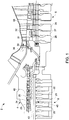
FIG. 1 is a cross-sectional schematic view of a turbomachine including a cross-over purge flow arrangement in accordance with an exemplary embodiment; -
FIG. 2 is a perspective view of a wheel member including a cross-over purge flow arrangement in accordance with the exemplary embodiment; -
FIG. 3 is a partial perspective view of a first side of the wheel member ofFIG. 2 ; -
FIG. 4 is a partial perspective view of a second side of the wheel member ofFIG. 2 ; -
FIG. 5 is a schematic view of the wheel member ofFIG. 2 illustrating a first cross-over flow circuit; -
FIG. 6 is a schematic view of the wheel member ofFIG. 2 illustrating a second cross-over flow circuit; and -
FIG. 7 is a schematic view of the rotor wheel ofFIG. 2 illustrating a cross-over flow zone on the wheel member ofFIG. 2 . - The detailed description explains embodiments of the invention, together with advantages and features, by way of example with reference to the drawings.
- With reference to
FIG. 1 , a turbomachine in accordance with an exemplary embodiment is indicated generally at 2.Turbomachine 2 includes ahousing 4 that surrounds acompressor portion 6 operatively connected to aturbine portion 8.Compressor portion 6 includes a plurality of rotor or wheel members, three of which are indicated at 20-22. Each wheel member 20-22 is operatively connected to corresponding pluralities of vanes or blades 23-25 that establish various stages ofcompressor portion 6. Similarly,turbine portion 8 includes a plurality of rotor or wheel members, three of which are indicated at 26-28. Each wheel member 26-28 is operatively connected to corresponding pluralities of vanes or blades 31-33 that establish various stages ofturbine section 8. - With this arrangement,
hot combustion gases 35 flowing from a combustor (not shown) enter ahot gas path 38 and flow intoturbine portion 8.Hot combustion gases 35 flow across vanes 31-33 ofturbine portion 8 developing mechanical energy. In addition, as will become more fully evident below,compressor flow 40 includes purge flows that are diverted into wheel members 20-22 to provide desired air flow. As will be discussed more fully below,wheel member 21 includes a cross-overpurge flow arrangement 45. - As best shown in
FIGs. 2-6 ,wheel member 21 includes abody 50 having afirst surface 54 that extends to an opposingsecond surface 55 through anintermediate portion 56.Wheel member 21 includes an outerdiametric surface 58 and acentral bore 60. Ablade mounting member 62 is provided on outerdiametric surface 58.Blade mounting member 62 provides an interface between the plurality ofblades 24 andwheel member 21. In accordance with the exemplary embodiment,wheel member 21 includes a first plurality ofpurge circuits 64 and a second plurality ofpurge circuits 68 arranged inbody 50 adjacent outerdiametric surface 58. First and second plurality ofpurge circuits body 50 and are separated by a plurality ofbolt passages 70. - In accordance with an exemplary embodiment, each of the first plurality of
purge circuits 64 extend about a first circumference ofwheel member 21 and include aconduit 72 having afirst end 74, exposed atsecond surface 55, that extends throughbody 50 to asecond end 75 that is exposed atfirst surface 54.First end 74 included aninlet channel 77 that extends fromconduit 72 towards outerdiametric surface 58.Second end 75 includes anoutlet channel 79 that extends fromconduit 72 towardscentral bore 60. With this arrangement, afirst purge flow 80 ofcompressor flow 40 passes fromextraction air passage 42 intoinlet channel 77.First purge flow 80 ofcompressor flow 40 passes alongconduit 72 towardsecond end 75 and exits throughoutlet channel 79 towardcentral bore 60. - In further accordance with the exemplary aspect, each of the second plurality of
purge circuits 68 extend along a second circumference ofwheel member 21 and include aconduit 83 having afirst end portion 85, exposed atsecond surface 55, that extends throughbody 50 to asecond end portion 86 exposed atfirst surface 54. In the exemplary embodiment shown, the first circumference is substantially similar to the second circumference. In addition, the first and second circumferences are arranged adjacent outerdiametric surface 58.First end portion 85 includes aninlet passage 88 that extends fromconduit 83 towardcentral bore 60.Second end portion 86 includes anoutlet passage 90 that extends fromconduit 83 toward outerdiametric surface 58. With this arrangement, asecond purge flow 95 ofcompressor flow 40 passes from a central bore (not separately labeled) ofwheel member 22, alongsecond surface 55 towardinlet passage 88.Second purge flow 95 ofcompressor flow 40 entersconduit 83, flows towardsecond end portion 86, and exits throughoutlet passage 90 toward outerdiametric surface 58 forming a cross-overpurge flow zone 100 such as shown inFIG. 7 . - At this point it should be understood that the exemplary embodiments enable a single rotating component to carry two or more fully independent cooling circuits. Moreover, the particular arrangement allows for higher purge flows as a result of increased pressure drops of the purge flow passing through the wheel member. In addition, it should be understood that the placement of the purge passage in relation to the bolt passages creates a key feature that simplifies construction. That is, the purge passages are independent of an orientation and/or alignment of the bolt passages on adjacent wheels. Also, while shown extending about a single circumference of the wheel member, the first and second pluralities of purge circuits could be arranged at different radial distances from the central bore. Finally, it should be understood that the first and second pluralities of purge circuits could be provided on other ones of the wheel members in the compressor portion, or on wheel members in the turbine portion.
- While the invention has been described in detail in connection with only a limited number of embodiments, it should be readily understood that the invention is not limited to such disclosed embodiments. Rather, the invention can be modified to incorporate any number of variations, alterations, substitutions or equivalent arrangements not heretofore described, but which are commensurate with the spirit and scope of the invention. Additionally, while various embodiments of the invention have been described, it is to be understood that aspects of the invention may include only some of the described embodiments. Accordingly, the invention is not to be seen as limited by the foregoing description, but is only limited by the scope of the appended claims.
Claims (14)
- A wheel member (20,21,22) comprising:a body (50) including a first surface (54) that extends to a second surface (55) through an intermediate portion (56), the body (50) including an outer diametric surface (58) and a central bore (60);a first plurality of purge circuits (64) formed in the body (50), the first plurality of purge circuits (64) extending from a first end (74) to a second end (75) through the body (50), the first plurality of purge circuits (64) being arranged to direct a first purge flow (80) in a first direction; anda second plurality of purge circuits (68) formed in the body (50) and fluidly isolated from the first plurality of purge circuits (64), the second plurality of purge circuits (68) extending from a first end portion (85) to a second end portion (86) through the body (50) and being arranged to direct a second purge flow (95) in a second direction, that is distinct from the first direction, to establish a cross-over purge flow (45).
- The wheel member (20,21,22) according to claim 1, further comprising: an inlet channel (77) extending from the first end (74) of each of the first plurality of purge circuits (64) toward the outer diametric surface (58).
- The wheel member (20,21,22) according to claim 1 or claim 2, further comprising: an outlet channel (79) extending from the second end (75) of each of the first plurality of purge circuits (64) toward the central bore (60).
- The wheel member (20,21,22) according to any of claims 1 to 3, further comprising: an inlet passage (88) extending from the first end portion (85) of each of the second plurality of purge circuits (68) toward the central bore (60).
- The wheel member (20,21,22) according to any of claims 1 to 4, further comprising: an outlet passage (90) extending from the second end portion (86) of each of the second plurality of purge circuits (68) toward the outer diametric surface (58).
- The wheel member (20,21,22)according to any of claims 1 to 5, further comprising: a plurality of bolt passages (70) formed in the body (50) between corresponding ones of the first plurality of purge circuits (64) and the second plurality of purge circuits (68).
- The wheel member (20,21,22) according to any preceding claim, wherein the first plurality of purge circuits (64) extend along a first circumference of the body (50) and the second plurality of purge circuits (68) extend along a second circumference of the body (50).
- The wheel member (20,21,22) according to claim 7, wherein the first circumference is substantially similar to the second circumference.
- The wheel member (20,21,22) according to claim 7 or 8, wherein each of the first and second circumferences are adjacent the outer diametric surface (58).
- The wheel member (20,21,22) according to any preceding claim, further comprising: a blade mounting member (62) arranged on the outer diametric surface (58).
- A turbomachine comprising:a compressor portion (6);a turbine portion (8) operatively connected to the compressor portion (6); andwherein at least one of the compressor portion (6) and turbine portion (8) includes a wheel member (20,21,22) as recited in any of claims 1 to 10.
- A method of delivering a cross-over purge flow in a turbomachine (2), the method comprising:passing a first purge flow (80) from a flowpath of the turbomachine (2) toward a wheel member (20,21,22);passing a second purge flow (95) from a wheel space of the turbomachine (2) along the wheel member;guiding the first purge flow through a first purge flow circuit (64) formed in the wheel member (20,21,22);guiding the second purge flow (95) through a second purge flow circuit (69), fluidly isolated from the first purge circuit (64), formed in the wheel member (20,21,22),discharging the first purge flow (80) from the first purge flow circuit (64) toward a central bore (60) of the wheel member (20,21,22); anddischarging the second purge flow (95) from the second purge flow circuit (68) toward the flow path establishing a cross-over purge flow (45) at the wheel member (20,21,22).
- The method of claim 12, further comprising: passing the first purge flow (80) through a central bore (60) of an adjacent wheel member (20,21,22).
- The method of claim 12 or 13, further comprising: directing the second purge flow (95) toward a plurality of blades (23-25) arranged on an outer diametric surface (58) of the wheel member (20,21,22).
Applications Claiming Priority (1)
| Application Number | Priority Date | Filing Date | Title |
|---|---|---|---|
| US13/020,499 US8807941B2 (en) | 2011-02-03 | 2011-02-03 | Cross-over purge flow system for a turbomachine wheel member |
Publications (3)
| Publication Number | Publication Date |
|---|---|
| EP2484866A2 true EP2484866A2 (en) | 2012-08-08 |
| EP2484866A3 EP2484866A3 (en) | 2017-03-15 |
| EP2484866B1 EP2484866B1 (en) | 2019-05-22 |
Family
ID=45558592
Family Applications (1)
| Application Number | Title | Priority Date | Filing Date |
|---|---|---|---|
| EP12153161.0A Active EP2484866B1 (en) | 2011-02-03 | 2012-01-30 | Cross-over purge flow system for a turbomachine wheel member |
Country Status (3)
| Country | Link |
|---|---|
| US (1) | US8807941B2 (en) |
| EP (1) | EP2484866B1 (en) |
| CN (1) | CN102628376B (en) |
Cited By (1)
| Publication number | Priority date | Publication date | Assignee | Title |
|---|---|---|---|---|
| WO2014197474A1 (en) * | 2013-06-05 | 2014-12-11 | Siemens Aktiengesellschaft | Rotor disc with fluid removal channels to enhance life of spindle bolt |
Families Citing this family (3)
| Publication number | Priority date | Publication date | Assignee | Title |
|---|---|---|---|---|
| US9664118B2 (en) * | 2013-10-24 | 2017-05-30 | General Electric Company | Method and system for controlling compressor forward leakage |
| US10208764B2 (en) * | 2016-02-25 | 2019-02-19 | General Electric Company | Rotor wheel and impeller inserts |
| FR3062415B1 (en) * | 2017-02-02 | 2019-06-07 | Safran Aircraft Engines | ROTOR OF TURBINE TURBINE ENGINE WITH VENTILATION BY LAMINATION |
Family Cites Families (10)
| Publication number | Priority date | Publication date | Assignee | Title |
|---|---|---|---|---|
| GB612097A (en) * | 1946-10-09 | 1948-11-08 | English Electric Co Ltd | Improvements in and relating to the cooling of gas turbine rotors |
| FR2695161B1 (en) * | 1992-08-26 | 1994-11-04 | Snecma | Cooling system for a turbomachine compressor and clearance control. |
| US6393829B2 (en) * | 1996-11-29 | 2002-05-28 | Hitachi, Ltd. | Coolant recovery type gas turbine |
| EP1033476B1 (en) * | 1999-03-03 | 2006-09-13 | General Electric Company | Heat exchange flow circuit for a turbine rotor |
| US6158102A (en) | 1999-03-24 | 2000-12-12 | General Electric Co. | Apparatus and methods for aligning holes through wheels and spacers and stacking the wheels and spacers to form a turbine rotor |
| EP1061234B1 (en) | 1999-06-16 | 2010-03-10 | General Electric Company | Gas turbine rotor with axial thermal medium delivery tube |
| DE60026236T2 (en) | 1999-08-24 | 2006-11-23 | General Electric Co. | Steam cooling system for a gas turbine |
| US7544039B1 (en) * | 2006-06-14 | 2009-06-09 | Florida Turbine Technologies, Inc. | Dual spool shaft with intershaft seal |
| US7993102B2 (en) * | 2009-01-09 | 2011-08-09 | General Electric Company | Rotor cooling circuit |
| US8186933B2 (en) * | 2009-03-24 | 2012-05-29 | General Electric Company | Systems, methods, and apparatus for passive purge flow control in a turbine |
-
2011
- 2011-02-03 US US13/020,499 patent/US8807941B2/en active Active
-
2012
- 2012-01-30 EP EP12153161.0A patent/EP2484866B1/en active Active
- 2012-02-02 CN CN201210029295.6A patent/CN102628376B/en active Active
Non-Patent Citations (1)
| Title |
|---|
| None |
Cited By (2)
| Publication number | Priority date | Publication date | Assignee | Title |
|---|---|---|---|---|
| WO2014197474A1 (en) * | 2013-06-05 | 2014-12-11 | Siemens Aktiengesellschaft | Rotor disc with fluid removal channels to enhance life of spindle bolt |
| US9951621B2 (en) | 2013-06-05 | 2018-04-24 | Siemens Aktiengesellschaft | Rotor disc with fluid removal channels to enhance life of spindle bolt |
Also Published As
| Publication number | Publication date |
|---|---|
| CN102628376A (en) | 2012-08-08 |
| CN102628376B (en) | 2015-06-17 |
| EP2484866B1 (en) | 2019-05-22 |
| US20120201652A1 (en) | 2012-08-09 |
| EP2484866A3 (en) | 2017-03-15 |
| US8807941B2 (en) | 2014-08-19 |
Similar Documents
| Publication | Publication Date | Title |
|---|---|---|
| US20140096538A1 (en) | Platform cooling of a turbine blade assembly | |
| CN204253116U (en) | For the protective housing sections of combustion gas turbine shell | |
| JP6105963B2 (en) | Connecting pipe seal assembly for turbomachine | |
| US8840370B2 (en) | Bucket assembly for turbine system | |
| US8444372B2 (en) | Passive cooling system for a turbomachine | |
| US8845289B2 (en) | Bucket assembly for turbine system | |
| US10358928B2 (en) | Airfoil with cooling circuit | |
| US20190218925A1 (en) | Turbine engine shroud | |
| US20190338651A1 (en) | Airfoil having cooling circuit | |
| EP3203024B1 (en) | Rotor blade and corresponding gas turbine | |
| EP2484866B1 (en) | Cross-over purge flow system for a turbomachine wheel member | |
| US8087871B2 (en) | Turbomachine compressor wheel member | |
| EP2666972A2 (en) | Turbine shroud cooling assembly for a gas turbine system and corresponding gas turbine system | |
| EP2597262B1 (en) | Bucket assembly for turbine system | |
| EP2530244B1 (en) | A stator assembly for surrounding a rotor and a method of cooling | |
| US9039370B2 (en) | Turbine nozzle | |
| US9551353B2 (en) | Compressor blade mounting arrangement | |
| CN103206260B (en) | For rotor wheel and the turbomachinery of turbomachinery | |
| US20120315139A1 (en) | Cooling flow control members for turbomachine buckets and method | |
| US9835087B2 (en) | Turbine bucket |
Legal Events
| Date | Code | Title | Description |
|---|---|---|---|
| PUAI | Public reference made under article 153(3) epc to a published international application that has entered the european phase |
Free format text: ORIGINAL CODE: 0009012 |
|
| AK | Designated contracting states |
Kind code of ref document: A2 Designated state(s): AL AT BE BG CH CY CZ DE DK EE ES FI FR GB GR HR HU IE IS IT LI LT LU LV MC MK MT NL NO PL PT RO RS SE SI SK SM TR |
|
| AX | Request for extension of the european patent |
Extension state: BA ME |
|
| PUAL | Search report despatched |
Free format text: ORIGINAL CODE: 0009013 |
|
| AK | Designated contracting states |
Kind code of ref document: A3 Designated state(s): AL AT BE BG CH CY CZ DE DK EE ES FI FR GB GR HR HU IE IS IT LI LT LU LV MC MK MT NL NO PL PT RO RS SE SI SK SM TR |
|
| AX | Request for extension of the european patent |
Extension state: BA ME |
|
| RIC1 | Information provided on ipc code assigned before grant |
Ipc: F01D 25/12 20060101ALI20170208BHEP Ipc: F01D 5/08 20060101ALI20170208BHEP Ipc: F01D 25/08 20060101ALI20170208BHEP Ipc: F01D 5/06 20060101ALI20170208BHEP Ipc: F01D 5/02 20060101AFI20170208BHEP |
|
| STAA | Information on the status of an ep patent application or granted ep patent |
Free format text: STATUS: REQUEST FOR EXAMINATION WAS MADE |
|
| 17P | Request for examination filed |
Effective date: 20170915 |
|
| RBV | Designated contracting states (corrected) |
Designated state(s): AL AT BE BG CH CY CZ DE DK EE ES FI FR GB GR HR HU IE IS IT LI LT LU LV MC MK MT NL NO PL PT RO RS SE SI SK SM TR |
|
| GRAP | Despatch of communication of intention to grant a patent |
Free format text: ORIGINAL CODE: EPIDOSNIGR1 |
|
| STAA | Information on the status of an ep patent application or granted ep patent |
Free format text: STATUS: GRANT OF PATENT IS INTENDED |
|
| INTG | Intention to grant announced |
Effective date: 20181219 |
|
| GRAS | Grant fee paid |
Free format text: ORIGINAL CODE: EPIDOSNIGR3 |
|
| GRAA | (expected) grant |
Free format text: ORIGINAL CODE: 0009210 |
|
| STAA | Information on the status of an ep patent application or granted ep patent |
Free format text: STATUS: THE PATENT HAS BEEN GRANTED |
|
| AK | Designated contracting states |
Kind code of ref document: B1 Designated state(s): AL AT BE BG CH CY CZ DE DK EE ES FI FR GB GR HR HU IE IS IT LI LT LU LV MC MK MT NL NO PL PT RO RS SE SI SK SM TR |
|
| REG | Reference to a national code |
Ref country code: GB Ref legal event code: FG4D |
|
| REG | Reference to a national code |
Ref country code: CH Ref legal event code: EP |
|
| REG | Reference to a national code |
Ref country code: IE Ref legal event code: FG4D |
|
| REG | Reference to a national code |
Ref country code: DE Ref legal event code: R096 Ref document number: 602012060288 Country of ref document: DE |
|
| REG | Reference to a national code |
Ref country code: AT Ref legal event code: REF Ref document number: 1136340 Country of ref document: AT Kind code of ref document: T Effective date: 20190615 |
|
| REG | Reference to a national code |
Ref country code: NL Ref legal event code: MP Effective date: 20190522 |
|
| REG | Reference to a national code |
Ref country code: LT Ref legal event code: MG4D |
|
| PG25 | Lapsed in a contracting state [announced via postgrant information from national office to epo] |
Ref country code: HR Free format text: LAPSE BECAUSE OF FAILURE TO SUBMIT A TRANSLATION OF THE DESCRIPTION OR TO PAY THE FEE WITHIN THE PRESCRIBED TIME-LIMIT Effective date: 20190522 Ref country code: NL Free format text: LAPSE BECAUSE OF FAILURE TO SUBMIT A TRANSLATION OF THE DESCRIPTION OR TO PAY THE FEE WITHIN THE PRESCRIBED TIME-LIMIT Effective date: 20190522 Ref country code: SE Free format text: LAPSE BECAUSE OF FAILURE TO SUBMIT A TRANSLATION OF THE DESCRIPTION OR TO PAY THE FEE WITHIN THE PRESCRIBED TIME-LIMIT Effective date: 20190522 Ref country code: NO Free format text: LAPSE BECAUSE OF FAILURE TO SUBMIT A TRANSLATION OF THE DESCRIPTION OR TO PAY THE FEE WITHIN THE PRESCRIBED TIME-LIMIT Effective date: 20190822 Ref country code: FI Free format text: LAPSE BECAUSE OF FAILURE TO SUBMIT A TRANSLATION OF THE DESCRIPTION OR TO PAY THE FEE WITHIN THE PRESCRIBED TIME-LIMIT Effective date: 20190522 Ref country code: PT Free format text: LAPSE BECAUSE OF FAILURE TO SUBMIT A TRANSLATION OF THE DESCRIPTION OR TO PAY THE FEE WITHIN THE PRESCRIBED TIME-LIMIT Effective date: 20190922 Ref country code: AL Free format text: LAPSE BECAUSE OF FAILURE TO SUBMIT A TRANSLATION OF THE DESCRIPTION OR TO PAY THE FEE WITHIN THE PRESCRIBED TIME-LIMIT Effective date: 20190522 Ref country code: ES Free format text: LAPSE BECAUSE OF FAILURE TO SUBMIT A TRANSLATION OF THE DESCRIPTION OR TO PAY THE FEE WITHIN THE PRESCRIBED TIME-LIMIT Effective date: 20190522 Ref country code: LT Free format text: LAPSE BECAUSE OF FAILURE TO SUBMIT A TRANSLATION OF THE DESCRIPTION OR TO PAY THE FEE WITHIN THE PRESCRIBED TIME-LIMIT Effective date: 20190522 |
|
| PG25 | Lapsed in a contracting state [announced via postgrant information from national office to epo] |
Ref country code: GR Free format text: LAPSE BECAUSE OF FAILURE TO SUBMIT A TRANSLATION OF THE DESCRIPTION OR TO PAY THE FEE WITHIN THE PRESCRIBED TIME-LIMIT Effective date: 20190823 Ref country code: BG Free format text: LAPSE BECAUSE OF FAILURE TO SUBMIT A TRANSLATION OF THE DESCRIPTION OR TO PAY THE FEE WITHIN THE PRESCRIBED TIME-LIMIT Effective date: 20190822 Ref country code: RS Free format text: LAPSE BECAUSE OF FAILURE TO SUBMIT A TRANSLATION OF THE DESCRIPTION OR TO PAY THE FEE WITHIN THE PRESCRIBED TIME-LIMIT Effective date: 20190522 Ref country code: LV Free format text: LAPSE BECAUSE OF FAILURE TO SUBMIT A TRANSLATION OF THE DESCRIPTION OR TO PAY THE FEE WITHIN THE PRESCRIBED TIME-LIMIT Effective date: 20190522 |
|
| REG | Reference to a national code |
Ref country code: AT Ref legal event code: MK05 Ref document number: 1136340 Country of ref document: AT Kind code of ref document: T Effective date: 20190522 |
|
| PG25 | Lapsed in a contracting state [announced via postgrant information from national office to epo] |
Ref country code: EE Free format text: LAPSE BECAUSE OF FAILURE TO SUBMIT A TRANSLATION OF THE DESCRIPTION OR TO PAY THE FEE WITHIN THE PRESCRIBED TIME-LIMIT Effective date: 20190522 Ref country code: DK Free format text: LAPSE BECAUSE OF FAILURE TO SUBMIT A TRANSLATION OF THE DESCRIPTION OR TO PAY THE FEE WITHIN THE PRESCRIBED TIME-LIMIT Effective date: 20190522 Ref country code: RO Free format text: LAPSE BECAUSE OF FAILURE TO SUBMIT A TRANSLATION OF THE DESCRIPTION OR TO PAY THE FEE WITHIN THE PRESCRIBED TIME-LIMIT Effective date: 20190522 Ref country code: AT Free format text: LAPSE BECAUSE OF FAILURE TO SUBMIT A TRANSLATION OF THE DESCRIPTION OR TO PAY THE FEE WITHIN THE PRESCRIBED TIME-LIMIT Effective date: 20190522 Ref country code: CZ Free format text: LAPSE BECAUSE OF FAILURE TO SUBMIT A TRANSLATION OF THE DESCRIPTION OR TO PAY THE FEE WITHIN THE PRESCRIBED TIME-LIMIT Effective date: 20190522 Ref country code: SK Free format text: LAPSE BECAUSE OF FAILURE TO SUBMIT A TRANSLATION OF THE DESCRIPTION OR TO PAY THE FEE WITHIN THE PRESCRIBED TIME-LIMIT Effective date: 20190522 |
|
| REG | Reference to a national code |
Ref country code: DE Ref legal event code: R097 Ref document number: 602012060288 Country of ref document: DE |
|
| PG25 | Lapsed in a contracting state [announced via postgrant information from national office to epo] |
Ref country code: SM Free format text: LAPSE BECAUSE OF FAILURE TO SUBMIT A TRANSLATION OF THE DESCRIPTION OR TO PAY THE FEE WITHIN THE PRESCRIBED TIME-LIMIT Effective date: 20190522 Ref country code: IT Free format text: LAPSE BECAUSE OF FAILURE TO SUBMIT A TRANSLATION OF THE DESCRIPTION OR TO PAY THE FEE WITHIN THE PRESCRIBED TIME-LIMIT Effective date: 20190522 |
|
| PLBE | No opposition filed within time limit |
Free format text: ORIGINAL CODE: 0009261 |
|
| STAA | Information on the status of an ep patent application or granted ep patent |
Free format text: STATUS: NO OPPOSITION FILED WITHIN TIME LIMIT |
|
| PG25 | Lapsed in a contracting state [announced via postgrant information from national office to epo] |
Ref country code: TR Free format text: LAPSE BECAUSE OF FAILURE TO SUBMIT A TRANSLATION OF THE DESCRIPTION OR TO PAY THE FEE WITHIN THE PRESCRIBED TIME-LIMIT Effective date: 20190522 |
|
| 26N | No opposition filed |
Effective date: 20200225 |
|
| PG25 | Lapsed in a contracting state [announced via postgrant information from national office to epo] |
Ref country code: PL Free format text: LAPSE BECAUSE OF FAILURE TO SUBMIT A TRANSLATION OF THE DESCRIPTION OR TO PAY THE FEE WITHIN THE PRESCRIBED TIME-LIMIT Effective date: 20190522 |
|
| PG25 | Lapsed in a contracting state [announced via postgrant information from national office to epo] |
Ref country code: SI Free format text: LAPSE BECAUSE OF FAILURE TO SUBMIT A TRANSLATION OF THE DESCRIPTION OR TO PAY THE FEE WITHIN THE PRESCRIBED TIME-LIMIT Effective date: 20190522 |
|
| PG25 | Lapsed in a contracting state [announced via postgrant information from national office to epo] |
Ref country code: MC Free format text: LAPSE BECAUSE OF FAILURE TO SUBMIT A TRANSLATION OF THE DESCRIPTION OR TO PAY THE FEE WITHIN THE PRESCRIBED TIME-LIMIT Effective date: 20190522 |
|
| REG | Reference to a national code |
Ref country code: CH Ref legal event code: PL |
|
| GBPC | Gb: european patent ceased through non-payment of renewal fee |
Effective date: 20200130 |
|
| REG | Reference to a national code |
Ref country code: BE Ref legal event code: MM Effective date: 20200131 |
|
| PG25 | Lapsed in a contracting state [announced via postgrant information from national office to epo] |
Ref country code: FR Free format text: LAPSE BECAUSE OF NON-PAYMENT OF DUE FEES Effective date: 20200131 Ref country code: GB Free format text: LAPSE BECAUSE OF NON-PAYMENT OF DUE FEES Effective date: 20200130 Ref country code: LU Free format text: LAPSE BECAUSE OF NON-PAYMENT OF DUE FEES Effective date: 20200130 |
|
| PG25 | Lapsed in a contracting state [announced via postgrant information from national office to epo] |
Ref country code: LI Free format text: LAPSE BECAUSE OF NON-PAYMENT OF DUE FEES Effective date: 20200131 Ref country code: CH Free format text: LAPSE BECAUSE OF NON-PAYMENT OF DUE FEES Effective date: 20200131 Ref country code: BE Free format text: LAPSE BECAUSE OF NON-PAYMENT OF DUE FEES Effective date: 20200131 |
|
| PG25 | Lapsed in a contracting state [announced via postgrant information from national office to epo] |
Ref country code: IE Free format text: LAPSE BECAUSE OF NON-PAYMENT OF DUE FEES Effective date: 20200130 |
|
| PG25 | Lapsed in a contracting state [announced via postgrant information from national office to epo] |
Ref country code: MT Free format text: LAPSE BECAUSE OF FAILURE TO SUBMIT A TRANSLATION OF THE DESCRIPTION OR TO PAY THE FEE WITHIN THE PRESCRIBED TIME-LIMIT Effective date: 20190522 Ref country code: CY Free format text: LAPSE BECAUSE OF FAILURE TO SUBMIT A TRANSLATION OF THE DESCRIPTION OR TO PAY THE FEE WITHIN THE PRESCRIBED TIME-LIMIT Effective date: 20190522 |
|
| PG25 | Lapsed in a contracting state [announced via postgrant information from national office to epo] |
Ref country code: MK Free format text: LAPSE BECAUSE OF FAILURE TO SUBMIT A TRANSLATION OF THE DESCRIPTION OR TO PAY THE FEE WITHIN THE PRESCRIBED TIME-LIMIT Effective date: 20190522 Ref country code: IS Free format text: LAPSE BECAUSE OF FAILURE TO SUBMIT A TRANSLATION OF THE DESCRIPTION OR TO PAY THE FEE WITHIN THE PRESCRIBED TIME-LIMIT Effective date: 20190922 |
|
| REG | Reference to a national code |
Ref country code: DE Ref legal event code: R082 Ref document number: 602012060288 Country of ref document: DE Ref country code: DE Ref legal event code: R081 Ref document number: 602012060288 Country of ref document: DE Owner name: GENERAL ELECTRIC TECHNOLOGY GMBH, CH Free format text: FORMER OWNER: GENERAL ELECTRIC COMPANY, SCHENECTADY, NY, US |
|
| PGFP | Annual fee paid to national office [announced via postgrant information from national office to epo] |
Ref country code: DE Payment date: 20251217 Year of fee payment: 15 |