EP2484579A2 - Suspended cab rollover protection system (rops) attachment for a 4WD agricultural tractor. - Google Patents
Suspended cab rollover protection system (rops) attachment for a 4WD agricultural tractor. Download PDFInfo
- Publication number
- EP2484579A2 EP2484579A2 EP12152836A EP12152836A EP2484579A2 EP 2484579 A2 EP2484579 A2 EP 2484579A2 EP 12152836 A EP12152836 A EP 12152836A EP 12152836 A EP12152836 A EP 12152836A EP 2484579 A2 EP2484579 A2 EP 2484579A2
- Authority
- EP
- European Patent Office
- Prior art keywords
- cab
- frame
- tractor
- spring
- limiter
- Prior art date
- Legal status (The legal status is an assumption and is not a legal conclusion. Google has not performed a legal analysis and makes no representation as to the accuracy of the status listed.)
- Granted
Links
Images

Classifications
-
- B—PERFORMING OPERATIONS; TRANSPORTING
- B62—LAND VEHICLES FOR TRAVELLING OTHERWISE THAN ON RAILS
- B62D—MOTOR VEHICLES; TRAILERS
- B62D33/00—Superstructures for load-carrying vehicles
- B62D33/06—Drivers' cabs
- B62D33/0604—Cabs insulated against vibrations or noise, e.g. with elastic suspension
-
- B—PERFORMING OPERATIONS; TRANSPORTING
- B60—VEHICLES IN GENERAL
- B60R—VEHICLES, VEHICLE FITTINGS, OR VEHICLE PARTS, NOT OTHERWISE PROVIDED FOR
- B60R21/00—Arrangements or fittings on vehicles for protecting or preventing injuries to occupants or pedestrians in case of accidents or other traffic risks
- B60R21/02—Occupant safety arrangements or fittings, e.g. crash pads
- B60R21/13—Roll-over protection
- B60R21/131—Protective devices for drivers in case of overturning of tractors
-
- B—PERFORMING OPERATIONS; TRANSPORTING
- B62—LAND VEHICLES FOR TRAVELLING OTHERWISE THAN ON RAILS
- B62D—MOTOR VEHICLES; TRAILERS
- B62D33/00—Superstructures for load-carrying vehicles
- B62D33/06—Drivers' cabs
- B62D33/0617—Drivers' cabs for tractors or off-the-road vehicles
Definitions
- the present invention relates to a device for suspending a cab on a work vehicle and, more particularly, to a cab suspension device that is also capable of transferring loads from the rollover protection systems (ROPS) to the vehicle chassis when required.
- ROPS rollover protection systems
- ROPS roll over protection systems
- a suspended cab with ROPS typically includes a bolted connection with a resilient isolation mount connecting the cab to the frame. Cab movement is limited through this type of connector, but it provides the load capability necessary for the ROPS. As this attachment is relatively rigid, adequate operator ride comfort may not be provided on heavy duty tractors.
- the present invention in any of the embodiments described herein, may provide one or more of the following advantages:
- a cab suspension device for an agricultural tractor comprising a pair of concentrically aligned tubes co-axially arranged around a conventional cab suspension spring apparatus.
- One of the pair of tubes is connected to the tractor frame while the second is attached to the cab frame.
- the lengths of the tubes are shorter than the static length of the spring apparatus to allow limited telescoping movement of the tubes during dynamic compression of the spring apparatus without causing contact between the tube ends and the opposing frames.
- the dynamic extension during telescoping movement of the spring apparatus is controlled by a spring retainer.
- An annular space between the tubes allows for limited lateral displacement of the spring apparatus without causing contact between the tubes.
- the limits are configured to permit normal operational movement of the spring apparatus without contact of the tubes. During vehicle roll over events, the normal operational loads of the spring apparatus are exceeded and the tubes will come in contact with one another and/or the opposing frame.
- the tubes and the spring retainer provide a rigid load transfer path for ROPS loads from the cab to the vehicle frame.
- FIG. 1 there is illustrated a tractor 5 which is a four-wheel drive tractor typically used for such purposes as agriculture, earthmoving, construction, and the like.
- the STX and TJ series four-wheel drive tractors manufactured by Case New Holland are typical examples of tractors of the type on which the present invention is beneficial.
- Such tractors feature relatively high horsepower engines for powering larger PTO-powered implements or for pulling large ground engaging implements and thus feature robustly designed chassis and drive systems.
- Tractor 5 includes a chassis 10 supported by front wheels 12 and by rear wheels 14 on either side thereof. It is typical in tractors of this type to feature only limited, if any, suspension movement between the wheels and the frame.
- An operator cab 16 is provided and is commonly supported by a suspension arrangement disposed between the chassis and the cab structure to improve operator comfort. While it is common to pivotally connect the forward end of cabs to tractor chassis and provide spring elements allowing vertical motion at the rear of the cab, such arrangement do not provide adequate ride quality in larger 4WD tractors.
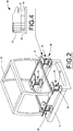
- a roll over protection system (ROPS) frame 20 is shown.
- the frame 20 is integrated into the structure of the cab 16 to strengthen the cab structure to withstand a vehicle roll over and thus protect the operator inside.
- the connection between the frame 20 and the vehicle chassis 10 must be capable of withstanding the roll over loads.
- the present invention provides a cab suspension system comprising a plurality of cab suspension devices 30 which interconnect the cab 16 and ROPS frame 20 with the vehicle chassis 10.
- a plurality of ROPS base supports 22 on the cab provide a convenient connection point for the suspension devices 30.
- the suspension devices 30 are configured to allow sufficient movement of the cab 16 for operator comfort, yet limit such movement when a roll over load must be transferred from the ROPS frame 20 to the chassis 10.
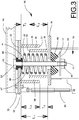
- FIG. 3 one embodiment of the cab suspension device 30 is shown comprising a cab mounting plate 32 and a chassis mounting plate 18.
- the mounting plates 18, 32 provide generally parallel and spaced-apart surfaces between which a spring 40 is positioned.
- Spring 40 is captured between the surfaces of plates 18, 32 and normally held in position by the weight of the cab.
- a spring retainer 41 with an upper retainer 42 and a lower nut 45 with a capture plate 44 is provided to limit the maximum spring extension and thus maximum extension of the suspension device 30.
- connection of spring retainer 41 to the cab mounting plate 32 includes a resilient isolator element 49 held in position by a washer 46 and a first spacer 53 to allow minor deflection of the spring retainer 41 relative to the cab mounting plate 32 without imposing significant bending loads on the retainer 41.
- First spacer 53 is positioned to maintain a pre-determined spacing between washer 46 and upper retainer 42 so that the isolator element 49 is not compressed by assembly of the spring retainer 41.
- the spring retainer 41 also features a second spacer 47 which maintains a predetermined spacing between the washer 46 and the capture plate 44.
- the first and second spacers 53, 47 allow the components of the spring retainer 41 assembly to be held rigidly together to prevent unintentional movement of the individual components which would result in noise.
- the configuration of the rigid spring retainer 41 assembly also minimizes bending loads on the retainer 41 that would result from lateral movement of the suspension device 30 thereby maintaining the spring retainer under generally tensile loading, even during roll over events.
- An aperture 17 in chassis mounting plate 18 is sized to be larger than the spring retainer 41 to allow limited lateral movement of the spring retainer 41 without contacting the mounting plate 18.
- space 19 is provide on the opposite side of mounting plate 18 to allow unrestricted movement of the lower portion of the spring retainer 41 and capture plate 44.
- Resilient bumper 48 engages the lower portion of spring retainer 41 adjacent to the capture plate 44 to further limit lateral deflection of the retainer 41 to minimize the potential for contact with the chassis or suspension device 30 structure.
- Alignment provisions may be provided on the plates 18, 32 to maintain the spring 40 generally centred on the axis of spring retainer 41 to prevent contact between the spring 40 and other components of the suspension device 30 during operation. Such provisions may include clamps to hold the spring ends in a fixed position or resilient members to urge the spring end into the desired positions. Resilient members are preferred for noise reduction qualities.
- a suspension damper 50 may be provided to introduce damping to the cab suspension system.
- Cab suspension device 30 also comprises first and second ROPS limiters 35, 36, respectively.
- first and second ROPS limiters 35, 36 are configured as generally cylindrical tubes co-axially arranged on a common axis with the spring 40.
- First ROPS limiter 35 is connected to the cab mounting plate 32 and extends downwardly while second ROPS limiter is connected to the chassis mounting plate 18 and extends upwardly therefrom.
- First ROPS limiter 35 has a larger diameter than second ROPS limiter 36 so that an annular space 39 exists when the ROPS limiters are co-axially arranged.
- the annular space is sufficient to permit lateral deflections anticipated during normal tractor operations without contact between the ROPS limiters 35, 36.
- the loadings on the suspension device 30 exceed normal operation loads, thus potentially causing greater lateral deflection of the spring 40 than the annular space 39 will permit.
- the first and second ROPS limiters will contact one another, preventing further lateral deflection of the spring 40 to provide a sufficiently capable load path for ROPS frame 20 loads from the cab to the vehicle chassis.
- each of the first and second ROPS limiters is less than the total space between the mounting plates 18, 32 when the spring 40 is at a nominal extension, illustrated by dimension L1 in FIG. 3 .
- the lengths of the first and second ROPS limiters 35, 36 are shown as L2 and L3.
- the difference in lengths between L1 and L2 or L3 determines the amount of spring 40 compression that may occur before the free ends 51, 52 of the ROPS limiters 35, 36 contact the opposing mounting plate 18, 32, represented by dimension "T".
- Dimension "T" is configured to allow normal cab movement without causing contact between the ROPS limiters 35, 36 and the opposing mounting plates 18, 32.
- the loadings on the suspension device 30 exceed normal operation loads, thus potentially causing greater vertical deflection of the spring 40 than the ROPS limiters 35, 36 will permit.
- the free ends of the first and second ROPS limiters will make contact with the opposing one another, preventing further vertical deflection of the spring 40 to provide a sufficiently capable load path for ROPS frame 20 loads from the cab to the vehicle chassis.
- the length of the first and second ROPS limiters 35, 36 is equal so that simultaneous contact between the free ends 51, 52 and the respective opposing mounting plates 18, 32 occurs; however, in the event that the lengths L2 or L3 differ, then the available travel distance will also vary, shown as T2 and T3. In this case, the ROPS limiter having the greater length will contact its respective opposing mounting plate first and bear the roll over load.
- the lengths of the first and second ROPS limiters 35, 36 are also selected so that the first and second ROPS limiters 35, 36 will remain overlapped during maximum extension of the suspension device 30. This is accomplished by selecting L2 and L3 so that the summation of the length exceeds that of the maximum extension allowed by spring retainer 41 and capture plate 44. This assures that the ROPS limiters 35, 36 will restrain lateral deflections of the suspension device, even under maximum extension of the suspension device.
- Resilient bumpers are incorporated in order to limit the impact of spring compression or extension to the limits allowed by the suspension device 30.
- a resilient bumper 48 is provided to cushion contact between capture plate 44 and the chassis mounting plate 18.
- a compression bumper 60 (shown in FIG. 2 ) is provided to cushion the impact of the ROPS limiters 35, 36 with their respective frame members.
- Compression bumper 60 comprises a resilient bumper element 61 configured to contact mounting plate 18 or a similar fixed member on the chassis. Bumper element 61 preferably makes contact with the mounting plate 18 prior to contact between the ROPS limiters 35, 36 and the opposing mounting plates 18, 32 so that normal operation suspension compressions are damped or cushioned during suspension compression.
- the structure of compression bumper 60 is designed to yield, as necessary, to allow the ROPS limiters 35, 36 to contact the opposing mounting plates 18, 32 and provide a stronger load path for the ROPS loads to the vehicle chassis.
- suspension elements of the cab suspension device 30 may be provided elsewhere on the tractor leaving the ROPS limiters 35, 36 and their opposing mounting plates 18, 32 in the device 30.
- the resultant device will still provide the necessary load path for transferring ROPS loads from the cab to the chassis, but will potentially result in a less compact assembly.
Landscapes
- Engineering & Computer Science (AREA)
- Mechanical Engineering (AREA)
- Chemical & Material Sciences (AREA)
- Combustion & Propulsion (AREA)
- Transportation (AREA)
- Body Structure For Vehicles (AREA)
- Vehicle Body Suspensions (AREA)
Abstract
Description
- The present invention relates to a device for suspending a cab on a work vehicle and, more particularly, to a cab suspension device that is also capable of transferring loads from the rollover protection systems (ROPS) to the vehicle chassis when required.
- Construction and agricultural machinery places considerable demands on the operator's cab suspension construction. In order to make the working environment of the driver comfortable, the suspension must be capable of reducing/eliminating the relatively powerful vibrations and shocks which are otherwise transmitted from the vehicle frame to the cab. Moreover, for reasons of safety, the suspension must be sufficiently strong to retain the cab on the frame even if the vehicle should overturn. Typical lighter duty agricultural tractor cab suspensions are designed with pivot connections at the front of the cab and vertical sprung connections at the rear of the cab. This arrangement has been found to be insufficient for heavier duty 4WD agricultural tractors which require moveable connections at the four corners of the cab mounting structure to provide adequate operator comfort. The movable connections must allow the cab to move freely without making hard contact during normal operation.
- Agricultural tractors are also required to provide roll over protection systems (ROPS) to protect the operator in the event of a vehicle roll over. A suspended cab with ROPS typically includes a bolted connection with a resilient isolation mount connecting the cab to the frame. Cab movement is limited through this type of connector, but it provides the load capability necessary for the ROPS. As this attachment is relatively rigid, adequate operator ride comfort may not be provided on heavy duty tractors.
- It would, therefore, be a great advantage to provide an improved mounting device for supporting a cab on an agricultural tractor frame that allows adequate movement for operator comfort while providing a sufficiently strong connection for transferring the ROPS loads to the frame. Further advantages would be realized by a mounting device that is sufficiently compact to be installed in a similar space occupied by a conventional spring mounting device. Still further advantages result from an improved cab suspension device that allows vertical, lateral and angular movement while still providing a suitably strong load transfer path for the ROPS loads when required.
- Accordingly, the present invention, in any of the embodiments described herein, may provide one or more of the following advantages:
- It is an object of the present invention to provide a cab mounting device for an agricultural tractor that allows movement for a cab suspension yet provides a rigid load transfer path between the cab ROPS and the tractor frame.
- It is another object of the present invention to provide a cab mounting device for an agricultural tractor that allows vertical, lateral, and angular cab movement during normal tractor operation.
- It is a further object of the present invention to provide a suspension device for a tractor cab having a roll over protection system that is similar in size to the normal cab suspension device it is intended to replace.
- It is a further object of the present invention to provide a cab suspension device for an agricultural tractor cab that incorporates resilient bumpers to minimize metal-to-metal contact within the device during normal operations.
- It is a still further object of the present invention to provide a cab suspension device for an agricultural tractor that is sufficiently robust to withstand expected tractor roll over loads without loss of structural integrity.
- It is a still further object of the present invention to provide a suspended cab mounting device for an agricultural tractor having a separate cab suspension apparatus wherein the mounting device will withstand tractor roll over loads without loss of structural integrity.
- It is a still further object of the present invention to provide a cab suspension device for a ROPS-equipped agricultural tractor that is durable in construction, inexpensive of manufacture, carefree of maintenance, easily assembled, and simple and effective to use.
- These and other objects are achieved by providing a cab suspension device for an agricultural tractor comprising a pair of concentrically aligned tubes co-axially arranged around a conventional cab suspension spring apparatus. One of the pair of tubes is connected to the tractor frame while the second is attached to the cab frame. The lengths of the tubes are shorter than the static length of the spring apparatus to allow limited telescoping movement of the tubes during dynamic compression of the spring apparatus without causing contact between the tube ends and the opposing frames. The dynamic extension during telescoping movement of the spring apparatus is controlled by a spring retainer. An annular space between the tubes allows for limited lateral displacement of the spring apparatus without causing contact between the tubes. The limits are configured to permit normal operational movement of the spring apparatus without contact of the tubes. During vehicle roll over events, the normal operational loads of the spring apparatus are exceeded and the tubes will come in contact with one another and/or the opposing frame. The tubes and the spring retainer provide a rigid load transfer path for ROPS loads from the cab to the vehicle frame.
- The advantages of this invention will be apparent upon consideration of the following detailed disclosure of the invention, especially when taken in conjunction with the accompanying drawings wherein:
-
FIG. 1 is a side elevation view of an agricultural tractor of the type on which the present invention is advantageous; -
FIG. 2 is a perspective view of a roll over protection system as it is attached to the tractor using a plurality of suspension mounts incorporating the present invention; -
FIG. 3 is an elevation view of a one of a plurality of cab suspension mounting devices presenting a first embodiment of the present invention; and -
FIG. 4 is a detail view fromFIG. 2 showing a vertical compression bumper. - Many of the fastening, connection, processes and other means and components utilized in this invention are widely known and used in the field of the invention described, and their exact nature or type is not necessary for an understanding and use of the invention by a person skilled in the art, and they will not therefore be discussed in significant detail. Also, any reference herein to the terms "forward" or "rearward," "left" or "right," "up" or "down," or "top" or "bottom" are used as a matter of mere convenience, and are determined by standing at the rear of the machine facing in its normal direction of travel. Furthermore, the various components shown or described herein for any specific application of this invention can be varied or altered as anticipated by this invention and the practice of a specific application of any element may already be widely known or used in the art by persons skilled in the art and each will likewise not therefore be discussed in significant detail. When referring to the figures, like parts are numbered the same in all of the figures.
- Referring now to the drawings, in
FIG. 1 there is illustrated atractor 5 which is a four-wheel drive tractor typically used for such purposes as agriculture, earthmoving, construction, and the like. The STX and TJ series four-wheel drive tractors manufactured by Case New Holland are typical examples of tractors of the type on which the present invention is beneficial. Such tractors feature relatively high horsepower engines for powering larger PTO-powered implements or for pulling large ground engaging implements and thus feature robustly designed chassis and drive systems. Tractor 5 includes achassis 10 supported byfront wheels 12 and byrear wheels 14 on either side thereof. It is typical in tractors of this type to feature only limited, if any, suspension movement between the wheels and the frame. Anoperator cab 16 is provided and is commonly supported by a suspension arrangement disposed between the chassis and the cab structure to improve operator comfort. While it is common to pivotally connect the forward end of cabs to tractor chassis and provide spring elements allowing vertical motion at the rear of the cab, such arrangement do not provide adequate ride quality in larger 4WD tractors. - Referring to
FIG. 2 in conjunction withFIG. 1 , a roll over protection system (ROPS)frame 20 is shown. Theframe 20 is integrated into the structure of thecab 16 to strengthen the cab structure to withstand a vehicle roll over and thus protect the operator inside. In order for theROPS frame 20 to properly function, the connection between theframe 20 and thevehicle chassis 10 must be capable of withstanding the roll over loads. The present invention provides a cab suspension system comprising a plurality ofcab suspension devices 30 which interconnect thecab 16 andROPS frame 20 with thevehicle chassis 10. A plurality of ROPS base supports 22 on the cab provide a convenient connection point for thesuspension devices 30. Thesuspension devices 30 are configured to allow sufficient movement of thecab 16 for operator comfort, yet limit such movement when a roll over load must be transferred from theROPS frame 20 to thechassis 10. - Now referring to
FIG. 3 , one embodiment of thecab suspension device 30 is shown comprising acab mounting plate 32 and achassis mounting plate 18. Themounting plates spring 40 is positioned.Spring 40 is captured between the surfaces ofplates spring retainer 41 with anupper retainer 42 and alower nut 45 with acapture plate 44 is provided to limit the maximum spring extension and thus maximum extension of thesuspension device 30. The connection ofspring retainer 41 to thecab mounting plate 32 includes aresilient isolator element 49 held in position by awasher 46 and afirst spacer 53 to allow minor deflection of thespring retainer 41 relative to thecab mounting plate 32 without imposing significant bending loads on theretainer 41. This provision is necessary since thesuspension device 30 may experience lateral and angular deflection in addition to vertical deflections.First spacer 53 is positioned to maintain a pre-determined spacing betweenwasher 46 andupper retainer 42 so that theisolator element 49 is not compressed by assembly of thespring retainer 41. Thespring retainer 41 also features asecond spacer 47 which maintains a predetermined spacing between thewasher 46 and thecapture plate 44. The first andsecond spacers spring retainer 41 assembly to be held rigidly together to prevent unintentional movement of the individual components which would result in noise. The configuration of therigid spring retainer 41 assembly also minimizes bending loads on theretainer 41 that would result from lateral movement of thesuspension device 30 thereby maintaining the spring retainer under generally tensile loading, even during roll over events. - An
aperture 17 inchassis mounting plate 18 is sized to be larger than thespring retainer 41 to allow limited lateral movement of thespring retainer 41 without contacting the mountingplate 18. Similarly,space 19 is provide on the opposite side of mountingplate 18 to allow unrestricted movement of the lower portion of thespring retainer 41 andcapture plate 44.Resilient bumper 48, discussed in further detail below, engages the lower portion ofspring retainer 41 adjacent to thecapture plate 44 to further limit lateral deflection of theretainer 41 to minimize the potential for contact with the chassis orsuspension device 30 structure. Alignment provisions may be provided on theplates spring 40 generally centred on the axis ofspring retainer 41 to prevent contact between thespring 40 and other components of thesuspension device 30 during operation. Such provisions may include clamps to hold the spring ends in a fixed position or resilient members to urge the spring end into the desired positions. Resilient members are preferred for noise reduction qualities. Asuspension damper 50 may be provided to introduce damping to the cab suspension system. -
Cab suspension device 30 also comprises first andsecond ROPS limiters second ROPS limiters spring 40.First ROPS limiter 35 is connected to thecab mounting plate 32 and extends downwardly while second ROPS limiter is connected to thechassis mounting plate 18 and extends upwardly therefrom. -
First ROPS limiter 35 has a larger diameter thansecond ROPS limiter 36 so that anannular space 39 exists when the ROPS limiters are co-axially arranged. The annular space is sufficient to permit lateral deflections anticipated during normal tractor operations without contact between theROPS limiters suspension device 30 exceed normal operation loads, thus potentially causing greater lateral deflection of thespring 40 than theannular space 39 will permit. In such instances, the first and second ROPS limiters will contact one another, preventing further lateral deflection of thespring 40 to provide a sufficiently capable load path forROPS frame 20 loads from the cab to the vehicle chassis. - The length of each of the first and second ROPS limiters is less than the total space between the mounting
plates spring 40 is at a nominal extension, illustrated by dimension L1 inFIG. 3 . The lengths of the first andsecond ROPS limiters spring 40 compression that may occur before the free ends 51, 52 of theROPS limiters plate ROPS limiters plates suspension device 30 exceed normal operation loads, thus potentially causing greater vertical deflection of thespring 40 than theROPS limiters spring 40 to provide a sufficiently capable load path forROPS frame 20 loads from the cab to the vehicle chassis. Ideally, the length of the first andsecond ROPS limiters plates - The lengths of the first and
second ROPS limiters second ROPS limiters suspension device 30. This is accomplished by selecting L2 and L3 so that the summation of the length exceeds that of the maximum extension allowed byspring retainer 41 andcapture plate 44. This assures that theROPS limiters - Resilient bumpers are incorporated in order to limit the impact of spring compression or extension to the limits allowed by the
suspension device 30. Duringspring 40 extension, aresilient bumper 48 is provided to cushion contact betweencapture plate 44 and thechassis mounting plate 18. Duringspring 40 compression, a compression bumper 60 (shown inFIG. 2 ) is provided to cushion the impact of theROPS limiters Compression bumper 60 comprises aresilient bumper element 61 configured to contact mountingplate 18 or a similar fixed member on the chassis.Bumper element 61 preferably makes contact with the mountingplate 18 prior to contact between theROPS limiters plates compression bumper 60 is designed to yield, as necessary, to allow theROPS limiters plates - It is noted that the suspension elements of the
cab suspension device 30 may be provided elsewhere on the tractor leaving theROPS limiters plates device 30. The resultant device will still provide the necessary load path for transferring ROPS loads from the cab to the chassis, but will potentially result in a less compact assembly.
Claims (15)
- A mounting device (30) for connecting in a spaced-apart relation a suspended cab (16) having a roll over protection structure (20) to an agricultural tractor frame (10), characterised by:a first limiter member (35) connected to the cab (16) for movement therewith, said first limiter (35) member having a first end portion (32) disposed adjacent to said cab (16), a first perimeter wall extending generally perpendicular from said first end portion (32) toward the frame (10) for a first length (L2), said first perimeter wall surrounding a first interior region arranged along an axis; anda second limiter member (36) connected to the frame (10) for movement therewith, said second limiter member (36) having a second end portion (18) disposed adjacent to the frame (10), a second perimeter wall extending generally perpendicular from said second end portion (18) toward the cab for a second length (L3), said second perimeter wall surrounding a second interior region arranged generally along said axis, said second perimeter wall configured to extend into said first interior region and create an annular space (39) between said first and said second perimeter walls, said first and said second lengths (L2 and L3)are each less than the distance (L1) separating said first and said second end portions (32 and 18) such that the cab (16) may move relative to the frame (10) under normal tractor (5) operation without causing contact between said first and said second limiter members (35 and 36), but upon a tractor rollover, said first and said second limiter members (35,36) contact each other thereby providing a robust connection to transfer structural loads from the roll over protection structure (20) to the frame (16).
- The mounting device (30) of Claim 1, further characterised by an extension limiter (41) configured to prevent separation of said first end portion (32) and said second end portion (18) beyond a predetermined maximum separation.
- The mounting device (30) of Claim 2, wherein the total of said first length (L2) and said second length (L3) is greater than said maximum separation.
- The mounting device (30) of Claim 2 or 3, further characterised by a spring (40) configured to maintain the space between the cab (16) and the frame (10) between a minimum separation and said maximum separation during normal tractor operation.
- The mounting device (30) of Claim 4, characterised in that said first and said second limiter members (35 and 36) do not contact one another as said spring (40) allows movement between said minimum separation and said maximum separation.
- The mounting device (30) of Claim 5, characterised in that said spring (40) is aligned on said axis.
- The mounting device (30) of any preceding Claim, characterised in that said first and said second perimeter walls are generally circular.
- The mounting device (30) of any preceding Claim, further characterised by a compression bumper (60) configured to cushion movement in the direction toward said minimum separation prior to contact of said first and said second limiter members (35 and 36).
- The mounting device (30) of any preceding Claim, further characterised by an extension bumper (48) configured to cushion movement in the direction toward said maximum extension prior to said maximum extension.
- A roll over protection structure connection device for a suspended cab (16) on an agricultural tractor (5), the tractor having a ground-supported chassis (10), the connection device characterised by a mounting device (30) as claimed in any preceding claim.
- The connection device of Claim 10, characterised in that said first and said second perimeter walls and said spring (40) are concentrically arranged on said axis.
- A method of transferring roll over protection structure loads from a suspended cab to a frame on an agricultural tractor, the method comprising the steps of:providing a plurality of connection devices (30) between the cab (16) and the frame (10);providing for each connection device (30) a first limiter member (35) connected to the cab (16) for movement therewith, said first limiter member (35) having a first end portion (32) disposed adjacent to said cab (16), a first perimeter wall extending generally perpendicular from the first end portion (32) toward the frame (10) for a first length (L2), the first perimeter wall surrounding a first interior region arranged along an axis;providing for each connection device (30) a second limiter member (36) connected to the frame (10) for movement therewith, the second limiter member (36) having a second end portion (18) disposed adjacent to the frame (10), a second perimeter wall extending generally perpendicular from the second end portion (18) toward the cab (16) for a second length (L3), the second perimeter wall surrounding a second interior region arranged generally along the axis, the second perimeter wall configured to extend into the first interior region and create an annular space (39) between the first and second perimeter walls;providing for each connection device (30) a spring (40) configured to maintain the space between the cab (16) and the frame (10) at each connection device (30) between a minimum separation and a maximum separation during normal tractor (5) operation;configuring for each connection device (30) the first and second lengths (L2 and L3) to less than the distance (L1) separating said the first and second end portions (32 and 18) and such that the sum of the first length (L2) and the second length (L3) is greater than the maximum separation;operating the tractor (5) normally to cause the cab (16) to move relative to the frame (10) without causing contact between the first and the second limiter members (35 and 36); anddeflecting by the connection devices (30) upon a tractor rollover, such that the first and said second limiter members (35 and 36) contact each other thereby providing a robust connection to transfer structural loads from the roll over protection structure (20) to the frame (10) .
- The method of Claim 12, further characterised by the step of:providing for each connection device (30) an extension limiter (41) configured to prevent separation of the first end portion (32) and the second end portion (18) beyond the maximum separation.
- The method of Claim 12 or 13, characterised in that the first and the second perimeter walls of each connection device (30) are generally circular about the axis.
- The method of Claim 12 to 14, characterised in that the first and second perimeter walls and the spring (40) of each connection device (30) are concentrically arranged on the axis.
Applications Claiming Priority (1)
| Application Number | Priority Date | Filing Date | Title |
|---|---|---|---|
| US13/019,886 US8430426B2 (en) | 2011-02-02 | 2011-02-02 | Suspended cab rollover protection system (ROPS) attachment for a 4WD agricultural tractor |
Publications (3)
| Publication Number | Publication Date |
|---|---|
| EP2484579A2 true EP2484579A2 (en) | 2012-08-08 |
| EP2484579A3 EP2484579A3 (en) | 2014-01-01 |
| EP2484579B1 EP2484579B1 (en) | 2016-11-09 |
Family
ID=45531782
Family Applications (1)
| Application Number | Title | Priority Date | Filing Date |
|---|---|---|---|
| EP12152836.8A Active EP2484579B1 (en) | 2011-02-02 | 2012-01-27 | Suspended cab rollover protection system (rops) attachment for a 4WD agricultural tractor. |
Country Status (2)
| Country | Link |
|---|---|
| US (1) | US8430426B2 (en) |
| EP (1) | EP2484579B1 (en) |
Cited By (5)
| Publication number | Priority date | Publication date | Assignee | Title |
|---|---|---|---|---|
| EP2868534A1 (en) * | 2013-11-01 | 2015-05-06 | CNH Industrial Italia S.p.A. | Rops retention system for a work vehicle. |
| EP3409568A1 (en) * | 2017-05-31 | 2018-12-05 | CLAAS Tractor S.A.S. | Damping system |
| EP3971043A1 (en) * | 2020-09-22 | 2022-03-23 | CLAAS Selbstfahrende Erntemaschinen GmbH | Agricultural machine |
| RU2838549C2 (en) * | 2020-09-22 | 2025-04-21 | КЛААС Зельбстфаренде Эрнтемашинен ГмбХ | Tractor |
| WO2025215297A1 (en) * | 2024-04-08 | 2025-10-16 | Ponsse Oyj | Cabin of work machine, work machine and method for designing cabin of work machine |
Families Citing this family (20)
| Publication number | Priority date | Publication date | Assignee | Title |
|---|---|---|---|---|
| EP2522879A3 (en) * | 2011-05-12 | 2017-09-20 | Carl Freudenberg KG | Assembly comprising a bearing and a tie rod |
| US8807633B2 (en) * | 2011-06-21 | 2014-08-19 | Cnh Industrial America Llc | Cab suspension system for an off-road vehicle |
| EP2934992B1 (en) * | 2012-12-20 | 2016-12-14 | CNH Industrial America LLC | Cab suspension system for a work vehicle with circumferentially extending bump stops |
| US9327774B2 (en) | 2014-10-06 | 2016-05-03 | Caterpillar Inc. | Mount apparatus for rollover protection system |
| US20150367897A1 (en) * | 2015-08-28 | 2015-12-24 | Caterpillar Paving Products Inc. | Adjustable cab system for machine |
| WO2017105303A1 (en) * | 2015-12-16 | 2017-06-22 | Saab Ab | Shock absorbing arrangement configured to withstand impact shock |
| US9982413B2 (en) * | 2016-10-03 | 2018-05-29 | Cnh Industrial America Llc | Cab suspension system for a work vehicle |
| RU178477U1 (en) * | 2017-07-24 | 2018-04-04 | Тенгизи Джемалиевич Дзоценидзе | WHEEL TRACTOR CAB |
| CN108100055A (en) * | 2017-11-24 | 2018-06-01 | 中联重机股份有限公司 | A kind of tractor cab |
| US10745065B2 (en) | 2018-04-16 | 2020-08-18 | Howe & Howe Inc. | Vehicle with pneumatically suspended operator compartment |
| ES2852898T3 (en) * | 2018-04-24 | 2021-09-14 | David Robertson | A rollover protection device |
| US10710645B2 (en) | 2018-08-31 | 2020-07-14 | Cnh Industrial America Llc | Vibration dampening system for a work vehicle with chassis dampers |
| US10752298B2 (en) | 2018-08-31 | 2020-08-25 | Cnh Industrial America Llc | Vibration dampening system for a work vehicle with elastomeric dampers |
| US10960936B2 (en) | 2018-08-31 | 2021-03-30 | Cnh Industrial America Llc | Vibration dampening system for a work vehicle with cab dampers |
| FI20215518A1 (en) * | 2021-05-04 | 2022-11-05 | Ponsse Oyj | Mobile machinery cab damping system |
| EP4124479A1 (en) * | 2021-07-30 | 2023-02-01 | Deere & Company | Cabin suspension system |
| US12358718B2 (en) * | 2021-10-25 | 2025-07-15 | Oshkosh Corporation | Body tie-down |
| CN113959736B (en) * | 2021-10-28 | 2023-07-25 | 中国煤炭科工集团太原研究院有限公司 | Coal mine underground vehicle ROPS cab detection test bed |
| US11970228B2 (en) * | 2022-01-26 | 2024-04-30 | Zoomlion Heavy Industry Na, Inc. | Docking station for supporting a remote wireless cab |
| US20250263133A1 (en) * | 2024-02-19 | 2025-08-21 | CNH Industrial Brasil Ltda. | System and method for work vehicle |
Family Cites Families (21)
| Publication number | Priority date | Publication date | Assignee | Title |
|---|---|---|---|---|
| US3560019A (en) | 1969-05-22 | 1971-02-02 | Portland Wire & Iron Works | Shock cushioning mounting means for canopies on heavy equipment |
| US3754315A (en) * | 1972-02-24 | 1973-08-28 | Int Harvester Co | Method and means for attaching protection structure to a vehicle frame |
| US3940177A (en) * | 1974-08-08 | 1976-02-24 | Caterpillar Tractor Co. | Vibration-isolated cab for tractors |
| US4116412A (en) * | 1977-07-15 | 1978-09-26 | Caterpillar Tractor Co. | Resilient mounting for an operator's station on a vehicle |
| US4149608A (en) | 1978-03-15 | 1979-04-17 | International Harvester Company | Tractor chassis and cab suspension system |
| US4294324A (en) | 1979-12-03 | 1981-10-13 | Time Commercial Financing Corporation | Cab suspension and restraining device |
| GB8619240D0 (en) | 1986-08-06 | 1986-09-17 | Dunlop Ltd | Elastomeric mounting |
| JPS6449735A (en) * | 1987-08-21 | 1989-02-27 | Hitachi Ltd | Damping vibration isolating mount |
| JP2585595Y2 (en) | 1993-02-22 | 1998-11-18 | 株式会社小松製作所 | Bulldozer Operator Cabin Support Device |
| US5388884A (en) * | 1993-04-21 | 1995-02-14 | Caterpillar Inc. | Arrangement for mounting a cab structure to a vehicle frame |
| US5893330A (en) * | 1997-07-10 | 1999-04-13 | Emery Properties, Inc. | Suspension apparatus |
| US5964310A (en) | 1997-12-12 | 1999-10-12 | Caterpillar Inc. | Operator's station supporting structure |
| DE69908290T2 (en) * | 1998-06-15 | 2004-05-06 | Hitachi Construction Machinery Co., Ltd. | CONSTRUCTION MACHINE WITH A CAB |
| JP4535599B2 (en) * | 2000-11-01 | 2010-09-01 | 株式会社小松製作所 | Construction vehicle cab support device |
| US6408970B1 (en) * | 2000-08-28 | 2002-06-25 | Allen L. Eng | Cab suspension system for terminal tractors |
| US6478102B1 (en) | 2001-04-21 | 2002-11-12 | International Truck Intellectual Property Company, L.L.C. | Vehicle body suspension system |
| SE521446C2 (en) | 2001-07-09 | 2003-11-04 | Volvo Wheel Loaders Ab | Device for hanging a cabin by a vehicle frame |
| JP4429595B2 (en) * | 2002-12-11 | 2010-03-10 | 株式会社小松製作所 | Cab support structure |
| DE602004015058D1 (en) | 2004-01-16 | 2008-08-28 | Same Deutz Fahr Group Spa | Spring-loaded roll protection |
| US20070278811A1 (en) | 2006-05-31 | 2007-12-06 | Derham Christopher D | System for operably coupling a vehicle cab to a vehicle |
| US20090289472A1 (en) | 2008-04-02 | 2009-11-26 | Catanzarite David M | Construction vehicle cab suspension mount |
-
2011
- 2011-02-02 US US13/019,886 patent/US8430426B2/en active Active
-
2012
- 2012-01-27 EP EP12152836.8A patent/EP2484579B1/en active Active
Non-Patent Citations (1)
| Title |
|---|
| None |
Cited By (5)
| Publication number | Priority date | Publication date | Assignee | Title |
|---|---|---|---|---|
| EP2868534A1 (en) * | 2013-11-01 | 2015-05-06 | CNH Industrial Italia S.p.A. | Rops retention system for a work vehicle. |
| EP3409568A1 (en) * | 2017-05-31 | 2018-12-05 | CLAAS Tractor S.A.S. | Damping system |
| EP3971043A1 (en) * | 2020-09-22 | 2022-03-23 | CLAAS Selbstfahrende Erntemaschinen GmbH | Agricultural machine |
| RU2838549C2 (en) * | 2020-09-22 | 2025-04-21 | КЛААС Зельбстфаренде Эрнтемашинен ГмбХ | Tractor |
| WO2025215297A1 (en) * | 2024-04-08 | 2025-10-16 | Ponsse Oyj | Cabin of work machine, work machine and method for designing cabin of work machine |
Also Published As
| Publication number | Publication date |
|---|---|
| US8430426B2 (en) | 2013-04-30 |
| US20120193157A1 (en) | 2012-08-02 |
| EP2484579A3 (en) | 2014-01-01 |
| EP2484579B1 (en) | 2016-11-09 |
Similar Documents
| Publication | Publication Date | Title |
|---|---|---|
| EP2484579B1 (en) | Suspended cab rollover protection system (rops) attachment for a 4WD agricultural tractor. | |
| US8807633B2 (en) | Cab suspension system for an off-road vehicle | |
| US5368118A (en) | Torsion bar suspension for operator's platform | |
| US10494039B2 (en) | Multiple degree of freedom cab suspension system | |
| EP2934992B1 (en) | Cab suspension system for a work vehicle with circumferentially extending bump stops | |
| US6340201B1 (en) | Anti-vibration support for construction machine cab | |
| EP2019883B1 (en) | An arrangement for suspension of an operator cab on a work machine frame | |
| CN100579851C (en) | Suspension with scissor telescoping mechanism | |
| US9327774B2 (en) | Mount apparatus for rollover protection system | |
| AU2016266057B2 (en) | Systems and methods for a material handling vehicle with a floor suspension | |
| DE102010009419A1 (en) | Impact buffer assembly for a vehicle | |
| EP2868534B1 (en) | Rops retention system for a work vehicle | |
| CN102219007A (en) | Device for fixing a roll bar or similar extension component on a vehicle | |
| US12065010B2 (en) | Work vehicle | |
| US10577021B2 (en) | Vehicle sub-frame | |
| US11926363B2 (en) | Work vehicle | |
| US20070131470A1 (en) | Vibration-isolating supporting structure | |
| US9022399B2 (en) | Vehicle cab suspension device | |
| JP4299050B2 (en) | Cab interior reinforcement structure | |
| KR101145805B1 (en) | An arrangement in connection with a vehicle cab | |
| US20250187680A1 (en) | Cab Suspension System | |
| US20150159729A1 (en) | Suspension assembly for payload carrier | |
| CA2105029C (en) | Suspension for operator's platform | |
| KR102344932B1 (en) | Device for supporting cabins of tractors | |
| EP1953011B1 (en) | Drawbar side cushioning for tractors |
Legal Events
| Date | Code | Title | Description |
|---|---|---|---|
| PUAI | Public reference made under article 153(3) epc to a published international application that has entered the european phase |
Free format text: ORIGINAL CODE: 0009012 |
|
| AK | Designated contracting states |
Kind code of ref document: A2 Designated state(s): AL AT BE BG CH CY CZ DE DK EE ES FI FR GB GR HR HU IE IS IT LI LT LU LV MC MK MT NL NO PL PT RO RS SE SI SK SM TR |
|
| AX | Request for extension of the european patent |
Extension state: BA ME |
|
| PUAL | Search report despatched |
Free format text: ORIGINAL CODE: 0009013 |
|
| AK | Designated contracting states |
Kind code of ref document: A3 Designated state(s): AL AT BE BG CH CY CZ DE DK EE ES FI FR GB GR HR HU IE IS IT LI LT LU LV MC MK MT NL NO PL PT RO RS SE SI SK SM TR |
|
| AX | Request for extension of the european patent |
Extension state: BA ME |
|
| RIC1 | Information provided on ipc code assigned before grant |
Ipc: B62D 33/06 20060101AFI20131125BHEP |
|
| RAP1 | Party data changed (applicant data changed or rights of an application transferred) |
Owner name: CNH INDUSTRIAL ITALIA S.P.A. |
|
| 17P | Request for examination filed |
Effective date: 20140701 |
|
| RBV | Designated contracting states (corrected) |
Designated state(s): AL AT BE BG CH CY CZ DE DK EE ES FI FR GB GR HR HU IE IS IT LI LT LU LV MC MK MT NL NO PL PT RO RS SE SI SK SM TR |
|
| GRAP | Despatch of communication of intention to grant a patent |
Free format text: ORIGINAL CODE: EPIDOSNIGR1 |
|
| INTG | Intention to grant announced |
Effective date: 20160601 |
|
| GRAS | Grant fee paid |
Free format text: ORIGINAL CODE: EPIDOSNIGR3 |
|
| GRAA | (expected) grant |
Free format text: ORIGINAL CODE: 0009210 |
|
| AK | Designated contracting states |
Kind code of ref document: B1 Designated state(s): AL AT BE BG CH CY CZ DE DK EE ES FI FR GB GR HR HU IE IS IT LI LT LU LV MC MK MT NL NO PL PT RO RS SE SI SK SM TR |
|
| REG | Reference to a national code |
Ref country code: GB Ref legal event code: FG4D |
|
| REG | Reference to a national code |
Ref country code: AT Ref legal event code: REF Ref document number: 843625 Country of ref document: AT Kind code of ref document: T Effective date: 20161115 Ref country code: CH Ref legal event code: EP |
|
| REG | Reference to a national code |
Ref country code: DE Ref legal event code: R084 Ref document number: 602012025069 Country of ref document: DE |
|
| REG | Reference to a national code |
Ref country code: IE Ref legal event code: FG4D |
|
| REG | Reference to a national code |
Ref country code: DE Ref legal event code: R096 Ref document number: 602012025069 Country of ref document: DE |
|
| REG | Reference to a national code |
Ref country code: FR Ref legal event code: PLFP Year of fee payment: 6 |
|
| REG | Reference to a national code |
Ref country code: GB Ref legal event code: 746 Effective date: 20170110 |
|
| PG25 | Lapsed in a contracting state [announced via postgrant information from national office to epo] |
Ref country code: LV Free format text: LAPSE BECAUSE OF FAILURE TO SUBMIT A TRANSLATION OF THE DESCRIPTION OR TO PAY THE FEE WITHIN THE PRESCRIBED TIME-LIMIT Effective date: 20161109 |
|
| REG | Reference to a national code |
Ref country code: LT Ref legal event code: MG4D |
|
| REG | Reference to a national code |
Ref country code: NL Ref legal event code: MP Effective date: 20161109 |
|
| REG | Reference to a national code |
Ref country code: AT Ref legal event code: MK05 Ref document number: 843625 Country of ref document: AT Kind code of ref document: T Effective date: 20161109 |
|
| PG25 | Lapsed in a contracting state [announced via postgrant information from national office to epo] |
Ref country code: NO Free format text: LAPSE BECAUSE OF FAILURE TO SUBMIT A TRANSLATION OF THE DESCRIPTION OR TO PAY THE FEE WITHIN THE PRESCRIBED TIME-LIMIT Effective date: 20170209 Ref country code: GR Free format text: LAPSE BECAUSE OF FAILURE TO SUBMIT A TRANSLATION OF THE DESCRIPTION OR TO PAY THE FEE WITHIN THE PRESCRIBED TIME-LIMIT Effective date: 20170210 Ref country code: SE Free format text: LAPSE BECAUSE OF FAILURE TO SUBMIT A TRANSLATION OF THE DESCRIPTION OR TO PAY THE FEE WITHIN THE PRESCRIBED TIME-LIMIT Effective date: 20161109 Ref country code: LT Free format text: LAPSE BECAUSE OF FAILURE TO SUBMIT A TRANSLATION OF THE DESCRIPTION OR TO PAY THE FEE WITHIN THE PRESCRIBED TIME-LIMIT Effective date: 20161109 Ref country code: NL Free format text: LAPSE BECAUSE OF FAILURE TO SUBMIT A TRANSLATION OF THE DESCRIPTION OR TO PAY THE FEE WITHIN THE PRESCRIBED TIME-LIMIT Effective date: 20161109 |
|
| PG25 | Lapsed in a contracting state [announced via postgrant information from national office to epo] |
Ref country code: IS Free format text: LAPSE BECAUSE OF FAILURE TO SUBMIT A TRANSLATION OF THE DESCRIPTION OR TO PAY THE FEE WITHIN THE PRESCRIBED TIME-LIMIT Effective date: 20170309 Ref country code: RS Free format text: LAPSE BECAUSE OF FAILURE TO SUBMIT A TRANSLATION OF THE DESCRIPTION OR TO PAY THE FEE WITHIN THE PRESCRIBED TIME-LIMIT Effective date: 20161109 Ref country code: HR Free format text: LAPSE BECAUSE OF FAILURE TO SUBMIT A TRANSLATION OF THE DESCRIPTION OR TO PAY THE FEE WITHIN THE PRESCRIBED TIME-LIMIT Effective date: 20161109 Ref country code: PT Free format text: LAPSE BECAUSE OF FAILURE TO SUBMIT A TRANSLATION OF THE DESCRIPTION OR TO PAY THE FEE WITHIN THE PRESCRIBED TIME-LIMIT Effective date: 20170309 Ref country code: ES Free format text: LAPSE BECAUSE OF FAILURE TO SUBMIT A TRANSLATION OF THE DESCRIPTION OR TO PAY THE FEE WITHIN THE PRESCRIBED TIME-LIMIT Effective date: 20161109 Ref country code: AT Free format text: LAPSE BECAUSE OF FAILURE TO SUBMIT A TRANSLATION OF THE DESCRIPTION OR TO PAY THE FEE WITHIN THE PRESCRIBED TIME-LIMIT Effective date: 20161109 Ref country code: PL Free format text: LAPSE BECAUSE OF FAILURE TO SUBMIT A TRANSLATION OF THE DESCRIPTION OR TO PAY THE FEE WITHIN THE PRESCRIBED TIME-LIMIT Effective date: 20161109 Ref country code: FI Free format text: LAPSE BECAUSE OF FAILURE TO SUBMIT A TRANSLATION OF THE DESCRIPTION OR TO PAY THE FEE WITHIN THE PRESCRIBED TIME-LIMIT Effective date: 20161109 Ref country code: BE Free format text: LAPSE BECAUSE OF NON-PAYMENT OF DUE FEES Effective date: 20170131 |
|
| PG25 | Lapsed in a contracting state [announced via postgrant information from national office to epo] |
Ref country code: CZ Free format text: LAPSE BECAUSE OF FAILURE TO SUBMIT A TRANSLATION OF THE DESCRIPTION OR TO PAY THE FEE WITHIN THE PRESCRIBED TIME-LIMIT Effective date: 20161109 Ref country code: DK Free format text: LAPSE BECAUSE OF FAILURE TO SUBMIT A TRANSLATION OF THE DESCRIPTION OR TO PAY THE FEE WITHIN THE PRESCRIBED TIME-LIMIT Effective date: 20161109 Ref country code: EE Free format text: LAPSE BECAUSE OF FAILURE TO SUBMIT A TRANSLATION OF THE DESCRIPTION OR TO PAY THE FEE WITHIN THE PRESCRIBED TIME-LIMIT Effective date: 20161109 Ref country code: RO Free format text: LAPSE BECAUSE OF FAILURE TO SUBMIT A TRANSLATION OF THE DESCRIPTION OR TO PAY THE FEE WITHIN THE PRESCRIBED TIME-LIMIT Effective date: 20161109 Ref country code: SK Free format text: LAPSE BECAUSE OF FAILURE TO SUBMIT A TRANSLATION OF THE DESCRIPTION OR TO PAY THE FEE WITHIN THE PRESCRIBED TIME-LIMIT Effective date: 20161109 |
|
| REG | Reference to a national code |
Ref country code: DE Ref legal event code: R097 Ref document number: 602012025069 Country of ref document: DE |
|
| PG25 | Lapsed in a contracting state [announced via postgrant information from national office to epo] |
Ref country code: BE Free format text: LAPSE BECAUSE OF FAILURE TO SUBMIT A TRANSLATION OF THE DESCRIPTION OR TO PAY THE FEE WITHIN THE PRESCRIBED TIME-LIMIT Effective date: 20161109 Ref country code: BG Free format text: LAPSE BECAUSE OF FAILURE TO SUBMIT A TRANSLATION OF THE DESCRIPTION OR TO PAY THE FEE WITHIN THE PRESCRIBED TIME-LIMIT Effective date: 20170209 Ref country code: SM Free format text: LAPSE BECAUSE OF FAILURE TO SUBMIT A TRANSLATION OF THE DESCRIPTION OR TO PAY THE FEE WITHIN THE PRESCRIBED TIME-LIMIT Effective date: 20161109 |
|
| REG | Reference to a national code |
Ref country code: CH Ref legal event code: PL |
|
| PLBE | No opposition filed within time limit |
Free format text: ORIGINAL CODE: 0009261 |
|
| STAA | Information on the status of an ep patent application or granted ep patent |
Free format text: STATUS: NO OPPOSITION FILED WITHIN TIME LIMIT |
|
| PG25 | Lapsed in a contracting state [announced via postgrant information from national office to epo] |
Ref country code: MC Free format text: LAPSE BECAUSE OF FAILURE TO SUBMIT A TRANSLATION OF THE DESCRIPTION OR TO PAY THE FEE WITHIN THE PRESCRIBED TIME-LIMIT Effective date: 20161109 |
|
| 26N | No opposition filed |
Effective date: 20170810 |
|
| PG25 | Lapsed in a contracting state [announced via postgrant information from national office to epo] |
Ref country code: LI Free format text: LAPSE BECAUSE OF NON-PAYMENT OF DUE FEES Effective date: 20170131 Ref country code: CH Free format text: LAPSE BECAUSE OF NON-PAYMENT OF DUE FEES Effective date: 20170131 |
|
| REG | Reference to a national code |
Ref country code: IE Ref legal event code: MM4A |
|
| PG25 | Lapsed in a contracting state [announced via postgrant information from national office to epo] |
Ref country code: LU Free format text: LAPSE BECAUSE OF NON-PAYMENT OF DUE FEES Effective date: 20170127 Ref country code: SI Free format text: LAPSE BECAUSE OF FAILURE TO SUBMIT A TRANSLATION OF THE DESCRIPTION OR TO PAY THE FEE WITHIN THE PRESCRIBED TIME-LIMIT Effective date: 20161109 |
|
| REG | Reference to a national code |
Ref country code: FR Ref legal event code: PLFP Year of fee payment: 7 |
|
| PG25 | Lapsed in a contracting state [announced via postgrant information from national office to epo] |
Ref country code: IE Free format text: LAPSE BECAUSE OF NON-PAYMENT OF DUE FEES Effective date: 20170127 |
|
| PG25 | Lapsed in a contracting state [announced via postgrant information from national office to epo] |
Ref country code: MT Free format text: LAPSE BECAUSE OF NON-PAYMENT OF DUE FEES Effective date: 20170127 |
|
| PG25 | Lapsed in a contracting state [announced via postgrant information from national office to epo] |
Ref country code: HU Free format text: LAPSE BECAUSE OF FAILURE TO SUBMIT A TRANSLATION OF THE DESCRIPTION OR TO PAY THE FEE WITHIN THE PRESCRIBED TIME-LIMIT; INVALID AB INITIO Effective date: 20120127 |
|
| PG25 | Lapsed in a contracting state [announced via postgrant information from national office to epo] |
Ref country code: CY Free format text: LAPSE BECAUSE OF NON-PAYMENT OF DUE FEES Effective date: 20161109 |
|
| PG25 | Lapsed in a contracting state [announced via postgrant information from national office to epo] |
Ref country code: MK Free format text: LAPSE BECAUSE OF FAILURE TO SUBMIT A TRANSLATION OF THE DESCRIPTION OR TO PAY THE FEE WITHIN THE PRESCRIBED TIME-LIMIT Effective date: 20161109 |
|
| PG25 | Lapsed in a contracting state [announced via postgrant information from national office to epo] |
Ref country code: TR Free format text: LAPSE BECAUSE OF FAILURE TO SUBMIT A TRANSLATION OF THE DESCRIPTION OR TO PAY THE FEE WITHIN THE PRESCRIBED TIME-LIMIT Effective date: 20161109 |
|
| REG | Reference to a national code |
Ref country code: DE Ref legal event code: R082 Ref document number: 602012025069 Country of ref document: DE Representative=s name: MEISSNER BOLTE PATENTANWAELTE RECHTSANWAELTE P, DE |
|
| PG25 | Lapsed in a contracting state [announced via postgrant information from national office to epo] |
Ref country code: AL Free format text: LAPSE BECAUSE OF FAILURE TO SUBMIT A TRANSLATION OF THE DESCRIPTION OR TO PAY THE FEE WITHIN THE PRESCRIBED TIME-LIMIT Effective date: 20161109 |
|
| PGFP | Annual fee paid to national office [announced via postgrant information from national office to epo] |
Ref country code: FR Payment date: 20240126 Year of fee payment: 13 |
|
| PG25 | Lapsed in a contracting state [announced via postgrant information from national office to epo] |
Ref country code: FR Free format text: LAPSE BECAUSE OF NON-PAYMENT OF DUE FEES Effective date: 20250131 |
|
| PGFP | Annual fee paid to national office [announced via postgrant information from national office to epo] |
Ref country code: GB Payment date: 20260126 Year of fee payment: 15 |
|
| PGFP | Annual fee paid to national office [announced via postgrant information from national office to epo] |
Ref country code: DE Payment date: 20260127 Year of fee payment: 15 |
|
| PGFP | Annual fee paid to national office [announced via postgrant information from national office to epo] |
Ref country code: IT Payment date: 20260123 Year of fee payment: 15 |