EP2484557A2 - Light distribution controlling apparatus of vehicle headlamp - Google Patents
Light distribution controlling apparatus of vehicle headlamp Download PDFInfo
- Publication number
- EP2484557A2 EP2484557A2 EP12153194A EP12153194A EP2484557A2 EP 2484557 A2 EP2484557 A2 EP 2484557A2 EP 12153194 A EP12153194 A EP 12153194A EP 12153194 A EP12153194 A EP 12153194A EP 2484557 A2 EP2484557 A2 EP 2484557A2
- Authority
- EP
- European Patent Office
- Prior art keywords
- vehicle
- headlamp
- light distribution
- afs
- offset
- Prior art date
- Legal status (The legal status is an assumption and is not a legal conclusion. Google has not performed a legal analysis and makes no representation as to the accuracy of the status listed.)
- Granted
Links
Images


Classifications
-
- B—PERFORMING OPERATIONS; TRANSPORTING
- B60—VEHICLES IN GENERAL
- B60Q—ARRANGEMENT OF SIGNALLING OR LIGHTING DEVICES, THE MOUNTING OR SUPPORTING THEREOF OR CIRCUITS THEREFOR, FOR VEHICLES IN GENERAL
- B60Q1/00—Arrangement of optical signalling or lighting devices, the mounting or supporting thereof or circuits therefor
- B60Q1/02—Arrangement of optical signalling or lighting devices, the mounting or supporting thereof or circuits therefor the devices being primarily intended to illuminate the way ahead or to illuminate other areas of way or environments
- B60Q1/04—Arrangement of optical signalling or lighting devices, the mounting or supporting thereof or circuits therefor the devices being primarily intended to illuminate the way ahead or to illuminate other areas of way or environments the devices being headlights
- B60Q1/14—Arrangement of optical signalling or lighting devices, the mounting or supporting thereof or circuits therefor the devices being primarily intended to illuminate the way ahead or to illuminate other areas of way or environments the devices being headlights having dimming means
- B60Q1/1415—Dimming circuits
- B60Q1/1423—Automatic dimming circuits, i.e. switching between high beam and low beam due to change of ambient light or light level in road traffic
- B60Q1/143—Automatic dimming circuits, i.e. switching between high beam and low beam due to change of ambient light or light level in road traffic combined with another condition, e.g. using vehicle recognition from camera images or activation of wipers
-
- B—PERFORMING OPERATIONS; TRANSPORTING
- B60—VEHICLES IN GENERAL
- B60Q—ARRANGEMENT OF SIGNALLING OR LIGHTING DEVICES, THE MOUNTING OR SUPPORTING THEREOF OR CIRCUITS THEREFOR, FOR VEHICLES IN GENERAL
- B60Q1/00—Arrangement of optical signalling or lighting devices, the mounting or supporting thereof or circuits therefor
- B60Q1/02—Arrangement of optical signalling or lighting devices, the mounting or supporting thereof or circuits therefor the devices being primarily intended to illuminate the way ahead or to illuminate other areas of way or environments
- B60Q1/04—Arrangement of optical signalling or lighting devices, the mounting or supporting thereof or circuits therefor the devices being primarily intended to illuminate the way ahead or to illuminate other areas of way or environments the devices being headlights
- B60Q1/06—Arrangement of optical signalling or lighting devices, the mounting or supporting thereof or circuits therefor the devices being primarily intended to illuminate the way ahead or to illuminate other areas of way or environments the devices being headlights adjustable, e.g. remotely-controlled from inside vehicle
- B60Q1/08—Arrangement of optical signalling or lighting devices, the mounting or supporting thereof or circuits therefor the devices being primarily intended to illuminate the way ahead or to illuminate other areas of way or environments the devices being headlights adjustable, e.g. remotely-controlled from inside vehicle automatically
- B60Q1/12—Arrangement of optical signalling or lighting devices, the mounting or supporting thereof or circuits therefor the devices being primarily intended to illuminate the way ahead or to illuminate other areas of way or environments the devices being headlights adjustable, e.g. remotely-controlled from inside vehicle automatically due to steering position
-
- B—PERFORMING OPERATIONS; TRANSPORTING
- B60—VEHICLES IN GENERAL
- B60Q—ARRANGEMENT OF SIGNALLING OR LIGHTING DEVICES, THE MOUNTING OR SUPPORTING THEREOF OR CIRCUITS THEREFOR, FOR VEHICLES IN GENERAL
- B60Q2300/00—Indexing codes for automatically adjustable headlamps or automatically dimmable headlamps
- B60Q2300/05—Special features for controlling or switching of the light beam
- B60Q2300/056—Special anti-blinding beams, e.g. a standard beam is chopped or moved in order not to blind
-
- B—PERFORMING OPERATIONS; TRANSPORTING
- B60—VEHICLES IN GENERAL
- B60Q—ARRANGEMENT OF SIGNALLING OR LIGHTING DEVICES, THE MOUNTING OR SUPPORTING THEREOF OR CIRCUITS THEREFOR, FOR VEHICLES IN GENERAL
- B60Q2300/00—Indexing codes for automatically adjustable headlamps or automatically dimmable headlamps
- B60Q2300/10—Indexing codes relating to particular vehicle conditions
- B60Q2300/11—Linear movements of the vehicle
- B60Q2300/112—Vehicle speed
-
- B—PERFORMING OPERATIONS; TRANSPORTING
- B60—VEHICLES IN GENERAL
- B60Q—ARRANGEMENT OF SIGNALLING OR LIGHTING DEVICES, THE MOUNTING OR SUPPORTING THEREOF OR CIRCUITS THEREFOR, FOR VEHICLES IN GENERAL
- B60Q2300/00—Indexing codes for automatically adjustable headlamps or automatically dimmable headlamps
- B60Q2300/10—Indexing codes relating to particular vehicle conditions
- B60Q2300/12—Steering parameters
- B60Q2300/122—Steering angle
-
- B—PERFORMING OPERATIONS; TRANSPORTING
- B60—VEHICLES IN GENERAL
- B60Q—ARRANGEMENT OF SIGNALLING OR LIGHTING DEVICES, THE MOUNTING OR SUPPORTING THEREOF OR CIRCUITS THEREFOR, FOR VEHICLES IN GENERAL
- B60Q2300/00—Indexing codes for automatically adjustable headlamps or automatically dimmable headlamps
- B60Q2300/40—Indexing codes relating to other road users or special conditions
- B60Q2300/41—Indexing codes relating to other road users or special conditions preceding vehicle
-
- B—PERFORMING OPERATIONS; TRANSPORTING
- B60—VEHICLES IN GENERAL
- B60Q—ARRANGEMENT OF SIGNALLING OR LIGHTING DEVICES, THE MOUNTING OR SUPPORTING THEREOF OR CIRCUITS THEREFOR, FOR VEHICLES IN GENERAL
- B60Q2300/00—Indexing codes for automatically adjustable headlamps or automatically dimmable headlamps
- B60Q2300/40—Indexing codes relating to other road users or special conditions
- B60Q2300/42—Indexing codes relating to other road users or special conditions oncoming vehicle
Definitions
- the present invention relates to a light distribution controlling apparatus controlling light distribution of a headlamp of a vehicle such as an automobile, and more particularly, to a light distribution controlling apparatus that can improve visibility of a front area of an own vehicle while preventing glare to a preceding vehicle or an oncoming vehicle that exists in front of the own vehicle.
- an adaptive driving beam (ADB) control is adapted.
- ADB adaptive driving beam
- a front vehicle such as the preceding vehicle or the oncoming vehicle
- a light distribution is controlled in order to shield an area corresponding to the detected front vehicle.
- a visibility of a front area can be improved by brightly lighting a possible wide area of the front area of the own vehicle where the front vehicle does not exist while preventing a glare to the front vehicle.
- a light distribution pattern is formed by adding an additional light distribution pattern onto an area above a cut-off line of a low beam light distribution pattern and the light distribution pattern with the additional light distribution pattern is swivel-controlled to correspond to a position of the front vehicle, so that a visibility of the front area in the own vehicle can be improved without dazzling the front vehicle.
- the ADB control although any problems do not particularly occur when the own vehicle travels a straight road, an uncomfortable feeling may be caused to the driver of the own vehicle by the light distribution control when the vehicle travels a curved road. For example, when the own vehicle travels a right-curved road and passes with the oncoming vehicle, since the detected position of the oncoming vehicle is relatively changed slowly from a right side to a left direction of the front area when viewed from the own vehicle, the ADB control swivels the light distribution to the left direction so as to follow the relative positional change of the oncoming vehicle.
- the headlamp is swiveled to the left direction and a mismatch between the traveling direction and a change in an irradiation direction deteriorates the visibility of the front area of the own vehicle while causing the discomfort for the driver of the own vehicle.
- an Adaptive front-lighting system (AFS) control in which an irradiation direction of the headlamp is swiveled horizontally so as to follow a change in a steering direction of the own vehicle.
- AFS Adaptive front-lighting system
- the irradiation direction of the headlamp is swivel-controlled in the traveling direction of the own vehicle by the AFS control so that the discomfort by the ADB control can be alleviated.
- both swivel angles of the ADB control and the AFS control may conflict to each other, and as a result, it may be difficult to allow the swivel controls to cooperate with each other.
- One or more embodiments of the invention relate to a light distribution controlling apparatus that improves visibility of a front area for a driver by allowing AFS control and ADB control to be in cooperation with each other in a vehicle headlamp with the AFS control and the ADB control.
- the embodiments relate to a light distribution controlling apparatus capable of alleviating discomfort for the driver in the ADB control.
- FIG. 1 is a conceptual configuration diagram of a light distribution controlling apparatus applied to a headlamp of a vehicle according to an exemplary embodiment of the present invention.
- a left headlamp LHL and a right headlamp RHL are mounted on left and right portions of the front side of the vehicle, respectively and light distribution of the headlamps is configured to be controlled by the light distribution controlling apparatus 100.
- the left and right headlamps (LHL and RHL) basically have the same configuration with each other, and for example, as the right headlamp RHL in FIG. 2 , a projector type lamp unit 2 is incorporated in a lamp housing 1 constituted by a lamp body 11 and a front cover 12 that is transparent.
- the lamp unit 2 is not described in detail herein, but includes a light source 21 constituted by a discharge bulb, a reflector 22 having a spheroidal shape, a projection lens 23 placed at a front position of the reflector 22, and a variable shade 24 that forms a pattern of light projected from the projection lens 23.
- the lamp unit 2 is configured to be supported on a bracket 3 placed in the lamp housing 1 and swivel-controlled horizontally, that is, to swing a light irradiation direction horizontally by a swivel actuator 4.
- the variable shade 24 includes a plurality of light shielding plates 242 having different shapes on the circumferential surface of a cylindrical main shaft 241.
- a rotational position of the variable shade 24 is variable in a shaft circumferential direction by a shade actuator 5.
- the light shielding plate 242 positioned on a lamp optical axis is changed by changing the rotational position to thereby change a light distribution pattern of light projected from the lamp unit 2.
- the discharge bulb 21 is turned ON in electrical connection with a discharge circuit unit 6.
- FIG. 3 is a diagram showing light distribution patterns of the left and right headlamps (LHL and RHL) controlled by the variable shade 24 and an overall light distribution pattern of the headlamps in which the light distribution patterns of the left and right headlamps (LHL and RHL) are overlapped with each other.
- LHL and RHL high beam light distribution RH without a cut-off line is formed at a first rotational position of the variable shade 24 and low beam light distribution RL with the cut-off line is formed at a third rotational position of the variable shade 24.
- variable shade 24 At a second rotational position of the variable shade 24, right high beam light distribution in which the high beam light distribution is formed in a right area and the low beam light distribution in a left area, herein, light distribution RM called right high light distribution is formed.
- light distribution RM called right high light distribution is formed in a left headlamp LHL of a vertical frame in FIG. 3 .
- high beam light distribution LH, low beam light distribution LL, and left high light distribution LM are formed based on the rotational positions of the variable shade 24.
- the light distribution controlling apparatus 100 includes an AFS controlling module 101 that horizontally swivel-controlls the irradiation directions of the left and right headlamps (LHL and RHL) of the own vehicle, a vehicle position detecting module 102 that detects the position of a vehicle which exists in the front area of the own vehicle, an offset processing module 103 that offset-processes the detected vehicle position based on an AFS swivel angle which is calculated by the AFS controlling module 101, and an ADB controlling module 104 that determines the light distribution patterns of the left and right headlamps (LHL and RHL) of the own vehicle based on the offset-processed vehicle position.
- AFS controlling module 101 that horizontally swivel-controlls the irradiation directions of the left and right headlamps (LHL and RHL) of the own vehicle
- a vehicle position detecting module 102 that detects the position of a vehicle which exists in the front area of the own vehicle
- an offset processing module 103 that offset-processe
- a vehicle velocity sensor SV to detect a vehicle velocity of the own vehicle and a steering angle sensor S ⁇ to detect a steering angle in link with a steering wheel of the own vehicle are connected to the AFS controlling module 101.
- the vehicle velocity V and the steering angle ⁇ detected by each sensor are used as control inputs.
- the AFS controlling module 101 includes an AFS swivel angle calculating module 105 that calculates an AFS swivel angle for lighting a traveling destination direction of the own vehicle after a predetermined time from a current point of time, for example, after several seconds by performing a predetermined calculation based on the vehicle velocity V and the steering angle ⁇ .
- the swivel angle calculating module 105 controls the swivel actuators 4 installed in the left and right headlamps (LHL and RHL) based on the calculated AFS swivel angle and separately swivel-controls the lamp units 2 of the left and right headlamps (LHL and RHL) horizontally to execute the AFS control. Meanwhile, the AFS swivel angle calculating module 105 may be configured to calculate the AFS swivel angle based on the information on the road which the own vehicle travels and in this case, the AFS controlling module 101 may be configured to use road information from a navigation device mounted on the own vehicle or road information acquired from a road traffic communication system.
- a photographing camera CAM to photograph the front area of the own vehicle is connected to the vehicle position detecting module 102 and the vehicle position detecting module 102 image-analyzes the photographed image by using the photographing camera CAM to detect the position of the front vehicle which exists in front of the own vehicle, that is, the oncoming vehicle or the preceding vehicle.
- the vehicle position detecting module 102 detects a front vehicle CAR which exits in the photographed image P as shown in FIG. 4A and detects both left and right ends of the vehicle, that is, detects that a right end position RE and a left end position LE are at which side of the left and right directions, respectively when viewed from the own vehicle are positioned with respect to a straight direction of the own vehicle, as the vehicle position of the detected front vehicle CAR.
- the offset processing module 103 offsets the detected vehicle position, that is, the right end position RE and the left end position LE horizontally based on the AFS swivel angle from the AFS controlling module 101.
- both the right end position RE and the left end position LE are offset at the same angle as the AFS swivel angle of each of the right headlamp RHL and the left headlamp LHL with respect to the right end position RE and the left end position LE detected, as shown in FIG. 4A , respectively, however, in an opposite direction to a swivel direction. That is, the offset processing of shifting the right end position RE and the left end position LE of FIG. 4A as in the arrows of FIG. 4A is performed and the offset vehicle position is outputted to the ADB controlling module 104.
- the ADB controlling module 104 determines the light distribution pattern based on the offset vehicle position.
- the ADB controlling module 104 includes a light distribution control map in order to determine the light distribution pattern and the offset vehicle position is applied to the light distribution control map to select any one of the predetermined light distribution patterns RH, RL, and RM or LH, LL, and LM shown in FIG. 3 with respect to each of the left and right headlamps.
- the light distributions of the headlamps is switched by driving and controlling the variable shade 24 of each of the left and right headlamps (LHL and RHL) based on the selected light distribution pattern, and as a result, the light distribution throughout the headlamp is controlled by any one of the high beam light distribution Hi, the low beam light distribution Lo, the right high light distribution RHi, the left high light distribution LHi, and the split light distribution SP.
- the ADB controlling module 104 has a light distribution control map M schematically shown in FIG. 4B .
- the light distribution control map M sets an area corresponding to the image P of the front area of the own vehicle photographed by the photographing camera CAM as an overall map area, and makes the center C of the overall map area be consistent with a straight direction of the own vehicle to set left and right end positions of a predetermined area including the center horizontally as a right base position RB and a left base position LB, respectively.
- the right end position RE and the left end position LE of the detected vehicle CAR are compared with the right base position RB and the left base end position LB, respectively to determine the light distribution pattern of each of the headlamps (LHL and RHL) from the comparison result.
- the detected vehicle when the right end position RE of the detected vehicle position is positioned at a further right side than the right base position RB, the detected vehicle is recognized as an approaching oncoming vehicle to be set as the low beam light distribution RL and when the right end position RE is positioned at a further left side than the right base position RB, the detected vehicle is recognized as a distant oncoming vehicle to be set as the right high light distribution RM.
- the left headlamp LHL when the left end position LE of the detected vehicle position is positioned at a further left side than the left base position LB, the detected vehicle is recognized as an approaching preceding vehicle to be set as the low beam light distribution LL and when the left end position LE is positioned at a further right side than the left base position LB, the detected vehicle is recognized as the distant preceding vehicle to be set as the left high light distribution LM. Meanwhile, when the front vehicle is never detected, the left and right headlamps (LHL and RHL) may be set as the high beam light distributions RH and LH, respectively.
- FIG. 5 is a flowchart describing the flow of light distribution control.
- the vehicle velocity sensor SV detects the vehicle velocity V of the own vehicle and the steering angle sensor S ⁇ detects the steering angle ⁇ of the own vehicle based on steering the steering wheel.
- the photographing camera CAM photographs the front area of the own vehicle to output a photographed image signal (step S11).
- the AFS controlling module 101 calculates the AFS swivel angle based on the detected vehicle velocity V and the detected steering angle ⁇ of the own vehicle (step S12).
- the AFS swivel angle is, for example, a swivel angle at which any one of left and right headlamps or both headlamps (LHL and RHL) irradiate a traveling destination by calculating the position of the traveling destination of the own vehicle by later a predetermined time, for example, later several seconds, than a current time based on the vehicle velocity and the steering angle when the vehicle travels a curved road.
- the AFS controlling module 101 controls the swivel actuator 4 of any one of the left and right headlamps or both headlamps (LHL and RHL) based on the calculated AFS swivel angle to horizontally deviatorily control an irradiation direction of the headlamp, that is, an irradiation optical axis of the lamp unit 2 (step S13).
- the vehicle position detecting module 102 image-analyzes the image signal of the front area of the own vehicle photographed by the photographing camera CAM to detect the front vehicle that exists in front of the own vehicle, that is, the oncoming vehicle or the preceding vehicle (step S14).
- the vehicle position detecting module 102 detects the front vehicle
- the vehicle position detecting module 102 detects the position of the front vehicle (step S15).
- the position of the vehicle includes the position of both width-direction ends of the detected vehicle CAR, that is, the right end position RE and the left end position LE of the detected vehicle when viewed from the own vehicle, as described in FIG. 4A .
- the offset processing module 103 offsets the detected vehicle position based on the AFS swivel angle calculated by the AFS controlling module 101 (step S16).
- the right end position RE of the detected vehicle is offset in an opposite direction at the AFS swivel angle of the right headlamp RHL and the left end position LE of the detected vehicle is offset in an opposite direction at the AFS swivel angle of the left headlamp LHL.
- the ADB controlling module 104 executes the ADB control based on the offset vehicle position to determine the light distribution patterns of the left and right headlamps (LHL and RHL).
- the ADB controlling module 104 drive-controls the variable shades 24 of the left and right headlamps based on the determined light distribution patterns to control the light distribution of light irradiated from each headlamp as shown in FIG. 3 (step S18). Meanwhile, in step S14, when the front vehicle is not detected, the vehicle position is set to a default value. In this case, the ADB controlling module 104 sets each of the headlamps (LHL and RHL) as the high beam light distribution.
- the light distribution controlling apparatus 100 determines the light distribution patterns of the left and right headlamps (LHL and RHL) based on the detected vehicle position in the ADB controlling module 104. For example, as shown in FIG. 6A1 , when the preceding vehicle CAR that exists in far front of the vehicle is detected, the right end position RE of the preceding vehicle CAR is positioned at the left side of a right base position RB, and as a result, the right headlamp RHL is set as right high light distribution RM, and the left end position LE is positioned at the right side of a left base position LB, and as a result, the left headlamp LHL is set as left high light distribution LM.
- the light distributions of the left and right headlamps overlap with each other to be a light distribution pattern by the split light distribution SP, as shown in FIG. 6A2 , to achieve light distribution that widely lights both areas of the preceding vehicle without dazzling the preceding vehicle CAR, thereby improving the visibility of the front area of the own vehicle.
- the right end position RE of the preceding vehicle CAR is positioned at the right side of the right base position RB, and as a result, the right headlamp RHL is set as low beam light distribution RL, and the left end position LE is positioned at the left side of the left base position LB, and as a result, the left headlamp LHL is set as low beam light distribution LL. Therefore, the light distributions of the left and right headlamps overlap with each other to be a light distribution pattern by low beam light distribution Lo, as shown in FIG. 6B2 , to achieve light distribution that secures the visibility of the previous area of the own vehicle without dazzling the preceding vehicle CAR.
- the right end position RE of the oncoming vehicle CAR is positioned at the right side of the right base position RB, and as a result, the right headlamp RHL is set as low beam light distribution RL and the left end position LE is positioned at the right side of the left base position LB, and as a result, the left headlamp LHL is set as left high light distribution LM. Therefore, the light distributions of the left and right headlamps overlap with each other, such that, as shown in FIG.
- the right area has a light distribution pattern by left high light distribution LHi in the low beam light distribution and the left area has the light distribution pattern by the left high light distribution LHi in the high beam light distribution to achieve light distribution that widely lights a front area at an own vehicle lane side without dazzling the oncoming vehicle CAR.
- the ADB controlling module 104 sets the right headlamp RHL as the low beam light distribution RL and the left headlamp LHL as the left high light distribution LH as shown in FIG. 7A2 .
- the left headlamp LHL is not swivel-controlled but is irradiated in a straight direction and the right headlamp RHL is swivel-controlled to the right side to light an area over the right direction from the straight direction of the own vehicle.
- the right headlamp RHL is controlled as the low beam light distribution RL by the ADB control while the right headlamp RHL is AFS swivel-controlled to the right side, the right area of the oncoming vehicle CAR is set as light distribution that lights only the previous area of the own vehicle, and as a result, the far front area cannot be lighted, thereby deteriorating the visibility of the right area.
- the offset processing module offsets the detected right end position RE of the oncoming vehicle CAR to correspond to the AFS swivel angle in the right headlamp RHL in an opposite direction at the same AFS swivel angle.
- the right end position RE is offset at the same angle as the AFS swivel angle in the left direction. For example, when the AFS swivel angle of the right headlamp RHL is 5°, the offset processing module 103 offsets the detected right end position RE to the left side by 5° in the light distribution control map M.
- the offset right end position REo is positioned at the left side of the right base position RB, and as a result, the ADB controlling module 104 sets the right headlamp RHL as the right high light distribution RM.
- the left high light distribution LM of the left headlamp LHL and the right high light distribution RM of the right headlamp RHL overlap with each other to be the light distribution pattern by the split light distribution SP.
- the width of a central light shielding area is expanded horizontally to light the right area up to a far front area without dazzling the oncoming vehicle CAR, thereby improving the visibility of the right area.
- the vehicle position is offset-compensated by considering the swivel of the light distribution by the AFS control to acquire light distribution that alleviates an influence by the AFS control.
- the AFS-controlled light distribution is not limited beyond necessity, such that the headlamp can be controlled by the light distribution to improve the visibility of the front area of the own vehicle.
- the right headlamp RHL when the right end position RE is not positioned at the left side of the right base position RB even though the right end position RE is offset, if the right headlamp RHL is set as the right high light distribution RM, the right headlamp RHL may cause glare to the oncoming vehicle CAR, and as a result, the light distribution of the right headlamp RHL needs to be maintained as the low beam light distribution as it is.
- the control of the light distribution of the oncoming vehicle when the own vehicle travels the right curved road has been described, but the detected left end position of the oncoming vehicle is offset in the right direction in the same manner even in the case where the left headlamp is AFS-swiveled to the left direction when the own vehicle travels the left curved road. Therefore, even when the ADB control is performed, the light distribution of the left headlamp can be prevented from being limited beyond necessity, thereby improving the visibility of the left area of the own vehicle.
- the detected right end position or the left end position of the preceding vehicle is offset in the same manner as above even in the case where the preceding vehicle is detected when the own vehicle travels the right curved or left curved road. Therefore, even though the light distribution that does not cause glare to the preceding vehicle is set by the ADB control, front lighting of the own vehicle is limited beyond necessity to prevent the visibility from being deteriorated.
- the vehicle position is offset in the offset processing module 103 based on the AFS swivel angle calculated in the AFS controlling module 101, but actually, the vehicle position may be offset based on the swivel angle of the headlamp which is AFS swivel-controlled.
- an angle sensor detecting the presently controlled swivel angle is installed in the swivel actuator 4 to feed back the swivel angle detected by the angle sensor to the offset processing module 103 as expressed by dashed line A1 of FIG. 1 . Since the vehicle position is offset based on the swivel angle which is actually AFS swivel-controlled, offset processing precision can be improved and light distribution precision can be improved.
- the ADB controlling module 104 ADB swivel-controls the determined light distribution patterns horizontally based on the detected vehicle position of the front vehicle, such that the light distribution pattern in one-side high light distribution or split light distribution can be moved as the front vehicle moves. For example, as expressed by dashed line A2 of FIG.
- the ADB controlling module 104 is configured to drive-control the swivel actuators 4 of the left and right headlamps (LHL and RHL) and the ADB controlling module 104 calculates how the front vehicle shifts to the right side or the left side from the detected vehicle position with respect to the straight direction of the own vehicle and horizontally swivel-controls the ADB-controlled light distribution pattern based on the calculated shift amount to completely prevent the dazzling with respect to the preceding vehicle or the oncoming vehicle and improve the visibility of an area other than the front vehicle.
- LHL and RHL left and right headlamps
- the ADB controlling module 104 for enabling the ADB swivel that swivels the ADB controlled light distribution horizontally
- the oncoming vehicle is detected as a vehicle that moves in the right direction toward the central area from the right end of the front area of the own vehicle.
- the ADB controlling module 104 when the light distribution control of the oncoming vehicle is performed, the ADB swivel control is performed to swivel the light distribution pattern in the left direction as the oncoming vehicle moves.
- the AFS swivel is performed in the right direction by the AFS control in the AFS controlling module 101 and the vehicle position is offset in an opposite direction to the AFS swivel to secure the light distribution in the AFS swiveled right area, thereby improving the visibility. Therefore, the driver cannot sense that a lighting area is moved to the left direction with the ADB swivel control to suppress the discomfort to the driver.
- the vehicle position (RE, LE) is offset based on the AFS swivel angle in the opposite direction of the swiveling
- the vehicle position (REo, LEo) after the offset and the right and left base positions (RB, LB) are compared, and the ADB control is executed based on the comparison.
- the same advantage as the above exemplary embodiment can be achieved, by offsetting the right and left base positions (RB, LB) based on the AFS swivel angle in the same direction of the swiveling, comparing the vehicle position (RE, LE) with the offset right and left base positions (RBo, LBo), and executing the ADB control based on the comparison. That is, as shown in FIG. 8 , the same control as the above exemplary embodiment can be executed by offsetting the right base position (RB) by an offset amount (ARoff) according to the AFS swivel angle, and comparing the offset right base position (RBo) and the right end position (RE) of the front vehicle (CAR). For example, as shown in FIG.
- a light distribution control of a vehicle headlamp may be carried out by the steps of:calculating an AFS swivel angle for lighting a traveling destination direction of an own vehicle after a predetermined time from a current point of time; swivelling an optical axis of a right headlamp (RHL) and an optical axis of a left headlamp (LHL) according to the calculated AFS swivel angle; detecting a vehicle position of a front vehicle (CAR) in front of the own vehicle by a camera (CAM); setting a center (C) which is consistent with a straight direction of the own vehicle, a right base position (RB) at a predetermined distance ( ⁇ RB) from the center (C) in a right direction, and a left base position (LB) at a predetermined distance ( ⁇ LB) from the center (C) in a left direction, in a light distribution control map (M) corresponding to an image (P) of a front area of the own vehicle
- a light distribution controlling apparatus of a vehicle headlamp may include: an ADB controlling module 104 configured to detect a vehicle position of a front vehicle CAR in front of an own vehicle and to switch light distribution of the vehicle headlamp based on the detected vehicle position; an AFS controlling module 101 configured to swivel-control an irradiation direction of the vehicle headlamp following a change of a traveling direction of the own vehicle; and an offset module 103 configured to offset said vehicle position adopted in the ADB controlling module 104 depending on a swivel angle controlled by the AFS controlling module 101.
- the offset module 103 may be configured to offset said vehicle position depending on a calculated swivel angle which is calculated by the AFS controlling module or the swiveled swivel angle of the headlamp which is swivel-controlled by the AFS controlling module.
- the AFS controlling module 104 may be capable of separately swivel-controlling left and right headlamps of the own vehicle.
- the offset module 103 may be configured to offset a right end position of the detected front vehicle CAR depending on a swivel angle of the right headlamp and to offset a left end position of the detected front vehicle CAR depending on a swivel angle of the left headlamp.
- the offset module 103 may be configured to offset the right end position depending on a calculated swivel angle of the right headlamp which is calculated by the AFS controlling module or the swiveled swivel angle of the right headlamp which is swivel-controlled by the AFS controlling module, and to offset the left end position depending on a calculated swivel angle of the left headlamp which is calculated by the AFS controlling module or the swiveled swivel angle of the left headlamp which is swivel-controlled by the AFS controlling module.
- the AFS-controlled headlamp when the AFS-controlled headlamp is ADB-controlled, by offsetting a vehicle position of the detected vehicle as a reference during the ADB control in an amount corresponding to an swivel amount of the headlamp by the AFS control, the ADB-controlled light distribution can be compensated to the swivel amount by the AFS control, thereby the visibility of the headlamp is prevented from being deteriorated.
- the uncomfortable with respect to the driver which is caused by swiveling the headlamp when the vehicle travels the curved road can be reduced.
- the present invention can be adopted in an apparatus for controlling the light distribution of a vehicle headlamp that enables the AFS control and the ADB control.
Landscapes
- Engineering & Computer Science (AREA)
- Mechanical Engineering (AREA)
- Lighting Device Outwards From Vehicle And Optical Signal (AREA)
- Non-Portable Lighting Devices Or Systems Thereof (AREA)
Abstract

Description
- The present invention relates to a light distribution controlling apparatus controlling light distribution of a headlamp of a vehicle such as an automobile, and more particularly, to a light distribution controlling apparatus that can improve visibility of a front area of an own vehicle while preventing glare to a preceding vehicle or an oncoming vehicle that exists in front of the own vehicle.
- In these light distribution controlling apparatuses, there is a type where an adaptive driving beam (ADB) control is adapted. According to the ADB control, when a front vehicle (such as the preceding vehicle or the oncoming vehicle) is detected, a light distribution is controlled in order to shield an area corresponding to the detected front vehicle. As a result, a visibility of a front area can be improved by brightly lighting a possible wide area of the front area of the own vehicle where the front vehicle does not exist while preventing a glare to the front vehicle. For example, according to a system described in
Patent Document 1, when the vehicle that exists in front of the own vehicle is detected, a light distribution pattern is formed by adding an additional light distribution pattern onto an area above a cut-off line of a low beam light distribution pattern and the light distribution pattern with the additional light distribution pattern is swivel-controlled to correspond to a position of the front vehicle, so that a visibility of the front area in the own vehicle can be improved without dazzling the front vehicle. - Patent Document 1:
JP-A-2010-000957 - In the above ADB control, although any problems do not particularly occur when the own vehicle travels a straight road, an uncomfortable feeling may be caused to the driver of the own vehicle by the light distribution control when the vehicle travels a curved road. For example, when the own vehicle travels a right-curved road and passes with the oncoming vehicle, since the detected position of the oncoming vehicle is relatively changed slowly from a right side to a left direction of the front area when viewed from the own vehicle, the ADB control swivels the light distribution to the left direction so as to follow the relative positional change of the oncoming vehicle. Therefore, even though the own vehicle travels while turning right, the headlamp is swiveled to the left direction and a mismatch between the traveling direction and a change in an irradiation direction deteriorates the visibility of the front area of the own vehicle while causing the discomfort for the driver of the own vehicle.
- In order to solve the above problem, it is considered to apply an Adaptive front-lighting system (AFS) control in which an irradiation direction of the headlamp is swiveled horizontally so as to follow a change in a steering direction of the own vehicle. If the AFS is applied to the headlamp adopting the ADB, the irradiation direction of the headlamp is swivel-controlled in the traveling direction of the own vehicle by the AFS control so that the discomfort by the ADB control can be alleviated. However, when the AFS control is applied to the ADB control, both swivel angles of the ADB control and the AFS control may conflict to each other, and as a result, it may be difficult to allow the swivel controls to cooperate with each other. Therefore, one control or both controls of the ADB control and the AFS control are complicated and lighting by inappropriate light distribution is made when both swivel controls are not in cooperation with each other. As a result, it may be difficult to implement an appropriate light distribution controlling apparatus with high visibility.
- One or more embodiments of the invention relate to a light distribution controlling apparatus that improves visibility of a front area for a driver by allowing AFS control and ADB control to be in cooperation with each other in a vehicle headlamp with the AFS control and the ADB control. In addition, the embodiments relate to a light distribution controlling apparatus capable of alleviating discomfort for the driver in the ADB control.
-
-
FIG. 1 is a conceptual configuration diagram of a light distribution controlling apparatus according to an exemplary embodiment. -
FIG. 2 is a schematic configuration diagram of a headlamp according to the exemplary embodiment. -
FIG. 3 is a diagram showing setting patterns of a light distribution pattern by left and right headlamps. -
FIG. 4A and FIG. 4B are diagrams describing detection and offsetting of a vehicle position. -
FIG. 5 is a flowchart of light distribution control in the exemplary embodiment. -
FIGS. 6A1, 6A2, 6B1, 6B2, 6C1 and 6C2 are diagrams describing light distribution patterns when ADB control is executed. -
FIGS. 7A1, 7A2, 7B1 and 7B2 are diagrams describing light distribution patterns when ADB control and AFS control are executed. -
FIG. 8 is a diagram describing about offsetting a base position, in a similar situation ofFIG. 7B1 . - Subsequently, embodiments of the present invention will be described with reference to the accompanying drawings. Further, the embodiments and modifications thereof described herein are not intended to limit the invention but only to exemplify the invention, and all features or combinations of the features of the embodiments and/or the modifications are not always essential to the invention.
-
FIG. 1 is a conceptual configuration diagram of a light distribution controlling apparatus applied to a headlamp of a vehicle according to an exemplary embodiment of the present invention. A left headlamp LHL and a right headlamp RHL are mounted on left and right portions of the front side of the vehicle, respectively and light distribution of the headlamps is configured to be controlled by the lightdistribution controlling apparatus 100. The left and right headlamps (LHL and RHL) basically have the same configuration with each other, and for example, as the right headlamp RHL inFIG. 2 , a projectortype lamp unit 2 is incorporated in alamp housing 1 constituted by alamp body 11 and afront cover 12 that is transparent. Thelamp unit 2 is not described in detail herein, but includes alight source 21 constituted by a discharge bulb, areflector 22 having a spheroidal shape, aprojection lens 23 placed at a front position of thereflector 22, and a variable shade 24 that forms a pattern of light projected from theprojection lens 23. Thelamp unit 2 is configured to be supported on abracket 3 placed in thelamp housing 1 and swivel-controlled horizontally, that is, to swing a light irradiation direction horizontally by aswivel actuator 4. The variable shade 24 includes a plurality oflight shielding plates 242 having different shapes on the circumferential surface of a cylindricalmain shaft 241. A rotational position of the variable shade 24 is variable in a shaft circumferential direction by ashade actuator 5. Thelight shielding plate 242 positioned on a lamp optical axis is changed by changing the rotational position to thereby change a light distribution pattern of light projected from thelamp unit 2. Thedischarge bulb 21 is turned ON in electrical connection with adischarge circuit unit 6. -
FIG. 3 is a diagram showing light distribution patterns of the left and right headlamps (LHL and RHL) controlled by the variable shade 24 and an overall light distribution pattern of the headlamps in which the light distribution patterns of the left and right headlamps (LHL and RHL) are overlapped with each other. In the right headlamp RHL of a horizontal frame inFIG. 3 , high beam light distribution RH without a cut-off line is formed at a first rotational position of the variable shade 24 and low beam light distribution RL with the cut-off line is formed at a third rotational position of the variable shade 24. At a second rotational position of the variable shade 24, right high beam light distribution in which the high beam light distribution is formed in a right area and the low beam light distribution in a left area, herein, light distribution RM called right high light distribution is formed. Similarly, in a left headlamp LHL of a vertical frame inFIG. 3 , high beam light distribution LH, low beam light distribution LL, and left high light distribution LM are formed based on the rotational positions of the variable shade 24. As a result, by overlapping the light distribution of the left and right headlamps (LHL and RHL) throughout the headlamp, lighting is made by high beam light distribution Hi, low beam light distribution Lo, right high light distribution RHi, left high light distribution LHi, and split light distribution SP with a concave center by overlapping the right high light distribution and the left high light distribution with each other, as shown inFIG. 3 . Meanwhile, high beam light distributions with different light intensity distributions can be acquired by overlapping lights of the left and right headlamps with respect to the high beam light distribution Hi. - Referring back to
FIG. 1 , the lightdistribution controlling apparatus 100 includes an AFS controllingmodule 101 that horizontally swivel-controlls the irradiation directions of the left and right headlamps (LHL and RHL) of the own vehicle, a vehicle position detecting module 102 that detects the position of a vehicle which exists in the front area of the own vehicle, anoffset processing module 103 that offset-processes the detected vehicle position based on an AFS swivel angle which is calculated by theAFS controlling module 101, and an ADB controllingmodule 104 that determines the light distribution patterns of the left and right headlamps (LHL and RHL) of the own vehicle based on the offset-processed vehicle position. - A vehicle velocity sensor SV to detect a vehicle velocity of the own vehicle and a steering angle sensor Sθ to detect a steering angle in link with a steering wheel of the own vehicle are connected to the
AFS controlling module 101. The vehicle velocity V and the steering angle θ detected by each sensor are used as control inputs. The AFS controllingmodule 101 includes an AFS swivelangle calculating module 105 that calculates an AFS swivel angle for lighting a traveling destination direction of the own vehicle after a predetermined time from a current point of time, for example, after several seconds by performing a predetermined calculation based on the vehicle velocity V and the steering angle θ. The swivelangle calculating module 105 controls theswivel actuators 4 installed in the left and right headlamps (LHL and RHL) based on the calculated AFS swivel angle and separately swivel-controls thelamp units 2 of the left and right headlamps (LHL and RHL) horizontally to execute the AFS control. Meanwhile, the AFS swivelangle calculating module 105 may be configured to calculate the AFS swivel angle based on the information on the road which the own vehicle travels and in this case, theAFS controlling module 101 may be configured to use road information from a navigation device mounted on the own vehicle or road information acquired from a road traffic communication system. - A photographing camera CAM to photograph the front area of the own vehicle is connected to the vehicle position detecting module 102 and the vehicle position detecting module 102 image-analyzes the photographed image by using the photographing camera CAM to detect the position of the front vehicle which exists in front of the own vehicle, that is, the oncoming vehicle or the preceding vehicle. The vehicle position detecting module 102 detects a front vehicle CAR which exits in the photographed image P as shown in
FIG. 4A and detects both left and right ends of the vehicle, that is, detects that a right end position RE and a left end position LE are at which side of the left and right directions, respectively when viewed from the own vehicle are positioned with respect to a straight direction of the own vehicle, as the vehicle position of the detected front vehicle CAR. - The
offset processing module 103 offsets the detected vehicle position, that is, the right end position RE and the left end position LE horizontally based on the AFS swivel angle from theAFS controlling module 101. In the offset processing, both the right end position RE and the left end position LE are offset at the same angle as the AFS swivel angle of each of the right headlamp RHL and the left headlamp LHL with respect to the right end position RE and the left end position LE detected, as shown inFIG. 4A , respectively, however, in an opposite direction to a swivel direction. That is, the offset processing of shifting the right end position RE and the left end position LE ofFIG. 4A as in the arrows ofFIG. 4A is performed and the offset vehicle position is outputted to theADB controlling module 104. - The
ADB controlling module 104 determines the light distribution pattern based on the offset vehicle position. TheADB controlling module 104 includes a light distribution control map in order to determine the light distribution pattern and the offset vehicle position is applied to the light distribution control map to select any one of the predetermined light distribution patterns RH, RL, and RM or LH, LL, and LM shown inFIG. 3 with respect to each of the left and right headlamps. The light distributions of the headlamps (LHL and RHL) is switched by driving and controlling the variable shade 24 of each of the left and right headlamps (LHL and RHL) based on the selected light distribution pattern, and as a result, the light distribution throughout the headlamp is controlled by any one of the high beam light distribution Hi, the low beam light distribution Lo, the right high light distribution RHi, the left high light distribution LHi, and the split light distribution SP. - That is, the
ADB controlling module 104 has a light distribution control map M schematically shown inFIG. 4B . The light distribution control map M sets an area corresponding to the image P of the front area of the own vehicle photographed by the photographing camera CAM as an overall map area, and makes the center C of the overall map area be consistent with a straight direction of the own vehicle to set left and right end positions of a predetermined area including the center horizontally as a right base position RB and a left base position LB, respectively. The right end position RE and the left end position LE of the detected vehicle CAR are compared with the right base position RB and the left base end position LB, respectively to determine the light distribution pattern of each of the headlamps (LHL and RHL) from the comparison result. For example, with respect to the right headlamp RHL, when the right end position RE of the detected vehicle position is positioned at a further right side than the right base position RB, the detected vehicle is recognized as an approaching oncoming vehicle to be set as the low beam light distribution RL and when the right end position RE is positioned at a further left side than the right base position RB, the detected vehicle is recognized as a distant oncoming vehicle to be set as the right high light distribution RM. Similarly, with respect to the left headlamp LHL, when the left end position LE of the detected vehicle position is positioned at a further left side than the left base position LB, the detected vehicle is recognized as an approaching preceding vehicle to be set as the low beam light distribution LL and when the left end position LE is positioned at a further right side than the left base position LB, the detected vehicle is recognized as the distant preceding vehicle to be set as the left high light distribution LM. Meanwhile, when the front vehicle is never detected, the left and right headlamps (LHL and RHL) may be set as the high beam light distributions RH and LH, respectively. - Subsequently, an operation of the light
distribution controlling apparatus 100 according to the embodiment configured as above will be described.FIG. 5 is a flowchart describing the flow of light distribution control. As the own vehicle travels; the vehicle velocity sensor SV detects the vehicle velocity V of the own vehicle and the steering angle sensor Sθ detects the steering angle θ of the own vehicle based on steering the steering wheel. Simultaneously, the photographing camera CAM photographs the front area of the own vehicle to output a photographed image signal (step S11). TheAFS controlling module 101 calculates the AFS swivel angle based on the detected vehicle velocity V and the detected steering angle θ of the own vehicle (step S12). The AFS swivel angle is, for example, a swivel angle at which any one of left and right headlamps or both headlamps (LHL and RHL) irradiate a traveling destination by calculating the position of the traveling destination of the own vehicle by later a predetermined time, for example, later several seconds, than a current time based on the vehicle velocity and the steering angle when the vehicle travels a curved road. TheAFS controlling module 101 controls theswivel actuator 4 of any one of the left and right headlamps or both headlamps (LHL and RHL) based on the calculated AFS swivel angle to horizontally deviatorily control an irradiation direction of the headlamp, that is, an irradiation optical axis of the lamp unit 2 (step S13). - Subsequently, the vehicle position detecting module 102 image-analyzes the image signal of the front area of the own vehicle photographed by the photographing camera CAM to detect the front vehicle that exists in front of the own vehicle, that is, the oncoming vehicle or the preceding vehicle (step S14). When the vehicle position detecting module 102 detects the front vehicle, the vehicle position detecting module 102 detects the position of the front vehicle (step S15). The position of the vehicle includes the position of both width-direction ends of the detected vehicle CAR, that is, the right end position RE and the left end position LE of the detected vehicle when viewed from the own vehicle, as described in
FIG. 4A . The offsetprocessing module 103 offsets the detected vehicle position based on the AFS swivel angle calculated by the AFS controlling module 101 (step S16). In the offset processing, the right end position RE of the detected vehicle is offset in an opposite direction at the AFS swivel angle of the right headlamp RHL and the left end position LE of the detected vehicle is offset in an opposite direction at the AFS swivel angle of the left headlamp LHL. Thereafter, theADB controlling module 104 executes the ADB control based on the offset vehicle position to determine the light distribution patterns of the left and right headlamps (LHL and RHL). TheADB controlling module 104 drive-controls the variable shades 24 of the left and right headlamps based on the determined light distribution patterns to control the light distribution of light irradiated from each headlamp as shown inFIG. 3 (step S18). Meanwhile, in step S14, when the front vehicle is not detected, the vehicle position is set to a default value. In this case, theADB controlling module 104 sets each of the headlamps (LHL and RHL) as the high beam light distribution. - As described above, the light
distribution controlling apparatus 100 according to the embodiment of the present invention determines the light distribution patterns of the left and right headlamps (LHL and RHL) based on the detected vehicle position in theADB controlling module 104. For example, as shown inFIG. 6A1 , when the preceding vehicle CAR that exists in far front of the vehicle is detected, the right end position RE of the preceding vehicle CAR is positioned at the left side of a right base position RB, and as a result, the right headlamp RHL is set as right high light distribution RM, and the left end position LE is positioned at the right side of a left base position LB, and as a result, the left headlamp LHL is set as left high light distribution LM. Therefore, the light distributions of the left and right headlamps overlap with each other to be a light distribution pattern by the split light distribution SP, as shown inFIG. 6A2 , to achieve light distribution that widely lights both areas of the preceding vehicle without dazzling the preceding vehicle CAR, thereby improving the visibility of the front area of the own vehicle. - As shown in
FIG. 6B1 , when the preceding vehicle CAR exists in short front of the own vehicle, the right end position RE of the preceding vehicle CAR is positioned at the right side of the right base position RB, and as a result, the right headlamp RHL is set as low beam light distribution RL, and the left end position LE is positioned at the left side of the left base position LB, and as a result, the left headlamp LHL is set as low beam light distribution LL. Therefore, the light distributions of the left and right headlamps overlap with each other to be a light distribution pattern by low beam light distribution Lo, as shown inFIG. 6B2 , to achieve light distribution that secures the visibility of the previous area of the own vehicle without dazzling the preceding vehicle CAR. - Alternatively, as shown in
FIG. 6C1 , when the oncoming vehicle CAR approaching the front side of the vehicle is detected, the right end position RE of the oncoming vehicle CAR is positioned at the right side of the right base position RB, and as a result, the right headlamp RHL is set as low beam light distribution RL and the left end position LE is positioned at the right side of the left base position LB, and as a result, the left headlamp LHL is set as left high light distribution LM. Therefore, the light distributions of the left and right headlamps overlap with each other, such that, as shown inFIG. 6C2 , the right area has a light distribution pattern by left high light distribution LHi in the low beam light distribution and the left area has the light distribution pattern by the left high light distribution LHi in the high beam light distribution to achieve light distribution that widely lights a front area at an own vehicle lane side without dazzling the oncoming vehicle CAR. - As described above, basic light distribution control in the present invention has been described when the own vehicle travels the straight road or the curved road. Hereinafter, a case where AFS control is performed when the own vehicle travels the curved road will be described. As shown in
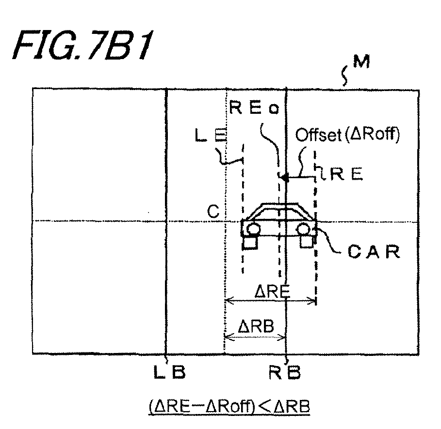
FIG. 7A1 , by detecting the oncoming vehicle approaching the own vehicle when the own vehicle travels a right curved road, when it is assumed that the right end position RE of the oncoming vehicle CAR is positioned at the right side of the right base position RB and the left end position LE is positioned at the right side of the left base position LB, theADB controlling module 104 sets the right headlamp RHL as the low beam light distribution RL and the left headlamp LHL as the left high light distribution LH as shown inFIG. 7A2 . In this case, when the AFS control is achieved in theAFS controlling module 101, the left headlamp LHL is not swivel-controlled but is irradiated in a straight direction and the right headlamp RHL is swivel-controlled to the right side to light an area over the right direction from the straight direction of the own vehicle. As described above, since the right headlamp RHL is controlled as the low beam light distribution RL by the ADB control while the right headlamp RHL is AFS swivel-controlled to the right side, the right area of the oncoming vehicle CAR is set as light distribution that lights only the previous area of the own vehicle, and as a result, the far front area cannot be lighted, thereby deteriorating the visibility of the right area. - Therefore, the offset processing module offsets the detected right end position RE of the oncoming vehicle CAR to correspond to the AFS swivel angle in the right headlamp RHL in an opposite direction at the same AFS swivel angle. As shown in
FIG. 7B1 , in a light distribution control map M, the right end position RE is offset at the same angle as the AFS swivel angle in the left direction. For example, when the AFS swivel angle of the right headlamp RHL is 5°, the offsetprocessing module 103 offsets the detected right end position RE to the left side by 5° in the light distribution control map M. The offset right end position REo is positioned at the left side of the right base position RB, and as a result, theADB controlling module 104 sets the right headlamp RHL as the right high light distribution RM. As a result, as shown inFIG. 7B2 , the left high light distribution LM of the left headlamp LHL and the right high light distribution RM of the right headlamp RHL overlap with each other to be the light distribution pattern by the split light distribution SP. In the split light distribution SP, since the right headlamp RHL is swivel-controlled to the right side, the width of a central light shielding area is expanded horizontally to light the right area up to a far front area without dazzling the oncoming vehicle CAR, thereby improving the visibility of the right area. - As described above, even though the headlamp is set as light distribution that does not cause glare to the oncoming vehicle by the
ADB controller 104 when the headlamp is AFS-swiveled by the AFS control, the vehicle position is offset-compensated by considering the swivel of the light distribution by the AFS control to acquire light distribution that alleviates an influence by the AFS control. As a result, the AFS-controlled light distribution is not limited beyond necessity, such that the headlamp can be controlled by the light distribution to improve the visibility of the front area of the own vehicle. - Herein, in the case of
FIG. 7B1 , when the right end position RE is not positioned at the left side of the right base position RB even though the right end position RE is offset, if the right headlamp RHL is set as the right high light distribution RM, the right headlamp RHL may cause glare to the oncoming vehicle CAR, and as a result, the light distribution of the right headlamp RHL needs to be maintained as the low beam light distribution as it is. - In
FIG. 7 , the control of the light distribution of the oncoming vehicle when the own vehicle travels the right curved road has been described, but the detected left end position of the oncoming vehicle is offset in the right direction in the same manner even in the case where the left headlamp is AFS-swiveled to the left direction when the own vehicle travels the left curved road. Therefore, even when the ADB control is performed, the light distribution of the left headlamp can be prevented from being limited beyond necessity, thereby improving the visibility of the left area of the own vehicle. The detected right end position or the left end position of the preceding vehicle is offset in the same manner as above even in the case where the preceding vehicle is detected when the own vehicle travels the right curved or left curved road. Therefore, even though the light distribution that does not cause glare to the preceding vehicle is set by the ADB control, front lighting of the own vehicle is limited beyond necessity to prevent the visibility from being deteriorated. - In the embodiment, the vehicle position is offset in the offset
processing module 103 based on the AFS swivel angle calculated in theAFS controlling module 101, but actually, the vehicle position may be offset based on the swivel angle of the headlamp which is AFS swivel-controlled. In this case, an angle sensor detecting the presently controlled swivel angle is installed in theswivel actuator 4 to feed back the swivel angle detected by the angle sensor to the offsetprocessing module 103 as expressed by dashed line A1 ofFIG. 1 . Since the vehicle position is offset based on the swivel angle which is actually AFS swivel-controlled, offset processing precision can be improved and light distribution precision can be improved. - In the present invention, the
ADB controlling module 104 ADB swivel-controls the determined light distribution patterns horizontally based on the detected vehicle position of the front vehicle, such that the light distribution pattern in one-side high light distribution or split light distribution can be moved as the front vehicle moves. For example, as expressed by dashed line A2 ofFIG. 1 , theADB controlling module 104 is configured to drive-control theswivel actuators 4 of the left and right headlamps (LHL and RHL) and theADB controlling module 104 calculates how the front vehicle shifts to the right side or the left side from the detected vehicle position with respect to the straight direction of the own vehicle and horizontally swivel-controls the ADB-controlled light distribution pattern based on the calculated shift amount to completely prevent the dazzling with respect to the preceding vehicle or the oncoming vehicle and improve the visibility of an area other than the front vehicle. - As described above, in the case of configuring the
ADB controlling module 104 for enabling the ADB swivel that swivels the ADB controlled light distribution horizontally, when the oncoming vehicle is detected as the own vehicle travels the right curved road, the oncoming vehicle is detected as a vehicle that moves in the right direction toward the central area from the right end of the front area of the own vehicle. As a result, in theADB controlling module 104, when the light distribution control of the oncoming vehicle is performed, the ADB swivel control is performed to swivel the light distribution pattern in the left direction as the oncoming vehicle moves. Therefore, even though the own vehicle travels in the right direction, the lighting of the own vehicle is swiveled in the left direction to cause a driver of the own vehicle to feel discomfort. However, in the present embodiment, the AFS swivel is performed in the right direction by the AFS control in theAFS controlling module 101 and the vehicle position is offset in an opposite direction to the AFS swivel to secure the light distribution in the AFS swiveled right area, thereby improving the visibility. Therefore, the driver cannot sense that a lighting area is moved to the left direction with the ADB swivel control to suppress the discomfort to the driver. - Further, according to the above exemplary embodiment, when the right and left headlamps are swiveled by the AFS control, the vehicle position (RE, LE) is offset based on the AFS swivel angle in the opposite direction of the swiveling, the vehicle position (REo, LEo) after the offset and the right and left base positions (RB, LB) are compared, and the ADB control is executed based on the comparison. However, it is apparent that the same advantage as the above exemplary embodiment can be achieved, by offsetting the right and left base positions (RB, LB) based on the AFS swivel angle in the same direction of the swiveling, comparing the vehicle position (RE, LE) with the offset right and left base positions (RBo, LBo), and executing the ADB control based on the comparison.
That is, as shown inFIG. 8 , the same control as the above exemplary embodiment can be executed by offsetting the right base position (RB) by an offset amount (ARoff) according to the AFS swivel angle, and comparing the offset right base position (RBo) and the right end position (RE) of the front vehicle (CAR). For example, as shown inFIG. 8 , when a distance (ΔRB+ΔRoff) from the center (C) to the offset right base position (RBo) is larger than a distance (ΔRE) from the center (C) to the right end position (RE) (that is, ΔRB+ΔRoff>ΔRE), the right headlamp (RHL) is controlled to form the right high light distribution (RM) in the similar manner asFIG. 7B2 . Further, the case (ΔRB+ΔRoff>ΔRE) in which "the distance (ΔRB+ΔRoff) from the center (C) to the offset right base position (RBo) is larger than the distance (ΔRRE) from the center (C) to the right end position (RE)" as shown inFIG.8 is equivalent to the case (ΔRE-ΔRoff<ΔRB) "a distance (ΔRE-ΔRoff) from the center (c) to the offset right end position (REo) is smaller than a distance (ΔRB) from the center (c) to the right base position" as shown inFIG. 7B1 .
As described in the above, in accordance with the above embodiments, a light distribution control of a vehicle headlamp may be carried out by the steps of:calculating an AFS swivel angle for lighting a traveling destination direction of an own vehicle after a predetermined time from a current point of time;
swivelling an optical axis of a right headlamp (RHL) and an optical axis of a left headlamp (LHL) according to the calculated AFS swivel angle;
detecting a vehicle position of a front vehicle (CAR) in front of the own vehicle by a camera (CAM);
setting a center (C) which is consistent with a straight direction of the own vehicle, a right base position (RB) at a predetermined distance (ΔRB) from the center (C) in a right direction, and a left base position (LB) at a predetermined distance (ΔLB) from the center (C) in a left direction, in a light distribution control map (M) corresponding to an image (P) of a front area of the own vehicle photographed by the camera (CAM);
determining a deviation amount (ARE) of a right end position (RE) of the detected front vehicle (CAR) from said center (C) and a deviation amount (ΔLE) of a left end position (LE) of the detected front vehicle (CAR) from said center (C), in the light distribution control map (M);
determining a right offset amount (ΔRoff) according to the AFS swivel angle of the right headlamp (RHL) and a left offset amount (ΔLoff) according to the AFS swivel angle of the left headlamp (LHL);
forming, by the right headlamp (RHL), a low beam light distribution (RL) in which cut-off lines are formed in both right area and left area of the optical axis of the right headlamp (RHL), in a case (ΔRE-ΔRoff>ΔRB, (the same as ΔRB+ΔRoff<ΔRE)) that a difference (ΔRE-ΔRoff) between the deviation amount (ARE) of the right end position (RE) of the detected front vehicle (CAR) from said center (C) and the right offset amount (ΔRoff) is larger than the distance (ΔRB) of the right base position (RB) from the center (C);
forming, by the right headlamp (RHL), a right high light distribution (RM) in which no cut-off line is formed in the right area of the optical axis of the right headlamp and the cut-off line is formed in the left area of the optical axis of the right headlamp, in a case (ΔRE-ΔRoff<ΔRB, (the same as ΔRB+ΔRoff>ΔRE)) that the difference (ΔRE-ΔRoff) between the deviation amount (ΔRE) of the right end position (RE) of the detected front vehicle (CAR) from said center (C) and the right offset amount (ΔRoff) is smaller than the distance (ΔRB) of the right base position (RB) from the center (C) (ΔRE-ΔRoff<ΔRB);
forming, by the left headlamp (LHL), a low beam light distribution (LL) in which cut-off lines are formed in both right area and left area of the optical axis of the left headlamp (LHL), in a case (ΔLE-ΔLoff>ΔLB, (the same as ΔLB+ΔLoff<ΔLE)) that a difference (ΔLE-ΔLoff) between the deviation amount (ΔLE) of the left end position (LE) of the detected front vehicle (CAR) from said center (C) and the left offset amount (ΔLoff) is larger than the distance (ΔLB) of the left base position (LB) from the center (C) (ΔLE-ΔLoff>ΔLB); and
forming, by the left headlamp (LHL), a left high light distribution (LM) in which no cut-off line is formed in the left area of the optical axis of the left headlamp and the cut-off line is formed in the right area of the optical axis of the left headlamp, in a case (ΔLE-ΔLoff<ΔLB, (the same as ΔLB+ΔLoff>ΔLE)) that the difference (ΔLE-ΔLoff) between the deviation amount (ΔLE) of the left end position (LE) of the detected front vehicle (CAR) from said center (C) and the left offset amount (ΔLoff) is smaller than the distance (ΔLB) of the left base position (RB) from the center (C) (ΔLE-ΔLoff<ΔLB). - Moreover, in accordance with the above embodiments, a light distribution controlling apparatus of a vehicle headlamp may include: an
ADB controlling module 104 configured to detect a vehicle position of a front vehicle CAR in front of an own vehicle and to switch light distribution of the vehicle headlamp based on the detected vehicle position; anAFS controlling module 101 configured to swivel-control an irradiation direction of the vehicle headlamp following a change of a traveling direction of the own vehicle; and an offsetmodule 103 configured to offset said vehicle position adopted in theADB controlling module 104 depending on a swivel angle controlled by theAFS controlling module 101. - In the above structure, the offset
module 103 may be configured to offset said vehicle position depending on a calculated swivel angle which is calculated by the AFS controlling module or the swiveled swivel angle of the headlamp which is swivel-controlled by the AFS controlling module. - In the above structure, the
AFS controlling module 104 may be capable of separately swivel-controlling left and right headlamps of the own vehicle. The offsetmodule 103 may be configured to offset a right end position of the detected front vehicle CAR depending on a swivel angle of the right headlamp and to offset a left end position of the detected front vehicle CAR depending on a swivel angle of the left headlamp. In addition, the offsetmodule 103 may be configured to offset the right end position depending on a calculated swivel angle of the right headlamp which is calculated by the AFS controlling module or the swiveled swivel angle of the right headlamp which is swivel-controlled by the AFS controlling module, and to offset the left end position depending on a calculated swivel angle of the left headlamp which is calculated by the AFS controlling module or the swiveled swivel angle of the left headlamp which is swivel-controlled by the AFS controlling module. - According to the above structure, when the AFS-controlled headlamp is ADB-controlled, by offsetting a vehicle position of the detected vehicle as a reference during the ADB control in an amount corresponding to an swivel amount of the headlamp by the AFS control, the ADB-controlled light distribution can be compensated to the swivel amount by the AFS control, thereby the visibility of the headlamp is prevented from being deteriorated. In addition, by improving a visibility at a side to which the headlamp is swiveled by the offsetting process of the vehicle position, the discomfort with respect to the driver which is caused by swiveling the headlamp when the vehicle travels the curved road can be reduced.
- The present invention can be adopted in an apparatus for controlling the light distribution of a vehicle headlamp that enables the AFS control and the ADB control.
Claims (5)
- A light distribution controlling apparatus of a vehicle headlamp comprising:an ADB controlling module (104) configured to detect a vehicle position of a front vehicle (CAR) in front of an own vehicle and to switch light distribution of the vehicle headlamp based on the detected vehicle position;an AFS controlling module (101) configured to swivel-control an irradiation direction of the vehicle headlamp depending on a change of a traveling direction of the own vehicle; andan offset module (103) configured to offset said vehicle position adopted in the ADB controlling module (104) depending on a swivel angle controlled by the AFS controlling module (101).
- The apparatus according to claim 1, wherein the offset module (103) is configured to offset said vehicle position depending on a calculated swivel angle which is calculated by the AFS controlling module or the swiveled swivel angle of the headlamp which is swivel-controlled by the AFS controlling module.
- The apparatus according to claim 1, wherein the AFS controlling module (104) is capable of separately swivel-controlling left and right headlamps of the own vehicle, and
wherein the offset module (103) is configured to offset a right end position of the detected front vehicle (CAR) depending on a swivel angle of the right headlamp and to offset a left end position of the detected front vehicle (CAR) depending on a swivel angle of the left headlamp. - The apparatus according to claim 3, wherein the offset module (103) is configured to offset the right end position depending on a calculated swivel angle of the right headlamp which is calculated by the AFS controlling module or the swiveled swivel angle of the right headlamp which is swivel-controlled by the AFS controlling module, and to offset the left end position depending on a calculated swivel angle of the left headlamp which is calculated by the AFS controlling module or the swiveled swivel angle of the left headlamp which is swivel-controlled by the AFS controlling module.
- A light distribution controlling method of a vehicle headlamp, the method comprising:calculating an AFS swivel angle for lighting a traveling destination direction of an own vehicle after a predetermined time from a current point of time;swivelling an optical axis of a right headlamp (RHL) and an optical axis of a left headlamp (LHL) according to the calculated AFS swivel angle;detecting a vehicle position of a front vehicle (CAR) in front of the own vehicle by a camera (CAM);setting a center (C) which is consistent with a straight direction of the own vehicle, a right base position (RB) at a predetermined distance (ΔRB) from the center (C) in a right direction, and a left base position (LB) at a predetermined distance (ΔLB) from the center (C) in a left direction, in a light distribution control map (M) corresponding to an image (P) of a front area of the own vehicle photographed by the camera (CAM);determining a deviation amount (ΔRE) of a right end position (RE) of the detected front vehicle (CAR) from said center (C) and a deviation amount (ΔLE) of a left end position (LE) of the detected front vehicle (CAR) from said center (C), in the light distribution control map (M);determining a right offset amount (ΔRoff) according to the AFS swivel angle of the right headlamp (RHL) and a left offset amount (ΔLoff) according to the AFS swivel angle of the left headlamp (LHL);forming, by the right headlamp (RHL), a low beam light distribution (RL) in which cut-off lines are formed in both right area and left area of the optical axis of the right headlamp (RHL), when a difference (ΔRE-ΔRoff) between the deviation amount (ΔRE) of the right end position (RE) of the detected front vehicle (CAR) from said center (C) and the right offset amount (ΔRoff) is larger than the distance (ΔRB) of the right base position (RB) from the center (C) (ΔRE-ΔRoff>ΔRB);forming, by the right headlamp (RHL), a right high light distribution (RM) in which no cut-off line is formed in the right area of the optical axis of the right headlamp and the cut-off line is formed in the left area of the optical axis of the right headlamp, when the difference (ΔRE-ΔRoff) between the deviation amount (ARE) of the right end position (RE) of the detected front vehicle (CAR) from said center (C) and the right offset amount (ΔRoff) is smaller than the distance (ΔRB) of the right base position (RB) from the center (C) (ΔRE-ΔRoff<ΔRB);forming, by the left headlamp (LHL), a low beam light distribution (LL) in which cut-off lines are formed in both right area and left area of the optical axis of the left headlamp (LHL), when a difference (ΔLE-ΔLoff) between the deviation amount (ALE) of the left end position (LE) of the detected front vehicle (CAR) from said center (C) and the left offset amount (ΔLoff) is larger than the distance (ΔLB) of the left base position (LB) from the center (C) (ΔLE-ΔLoff>ΔLB); andforming, by the left headlamp (LHL), a left high light distribution (LM) in which no cut-off line is formed in the left area of the optical axis of the left headlamp and the cut-off line is formed in the right area of the optical axis of the left headlamp, when the difference (ΔLE-ΔLlLoff) between the deviation amount (ALE) of the left end position (LE) of the detected front vehicle (CAR) from said center (C) and the left offset amount (ΔLoff is smaller than the distance (ALB) of the left base position (RB) from the center (C) (ΔLE-ΔLoff<ΔLB).
Applications Claiming Priority (1)
| Application Number | Priority Date | Filing Date | Title |
|---|---|---|---|
| JP2011022244A JP5719620B2 (en) | 2011-02-04 | 2011-02-04 | Light distribution control device for vehicle headlamp |
Publications (3)
| Publication Number | Publication Date |
|---|---|
| EP2484557A2 true EP2484557A2 (en) | 2012-08-08 |
| EP2484557A3 EP2484557A3 (en) | 2015-12-30 |
| EP2484557B1 EP2484557B1 (en) | 2019-07-17 |
Family
ID=45558595
Family Applications (1)
| Application Number | Title | Priority Date | Filing Date |
|---|---|---|---|
| EP12153194.1A Active EP2484557B1 (en) | 2011-02-04 | 2012-01-31 | Light distribution controlling apparatus of vehicle headlamp |
Country Status (2)
| Country | Link |
|---|---|
| EP (1) | EP2484557B1 (en) |
| JP (1) | JP5719620B2 (en) |
Cited By (10)
| Publication number | Priority date | Publication date | Assignee | Title |
|---|---|---|---|---|
| CN104470056A (en) * | 2013-09-23 | 2015-03-25 | 海拉胡克双合有限公司 | Method for controlling illumination of road profile |
| FR3022326A1 (en) * | 2014-06-16 | 2015-12-18 | Valeo Vision | ROTARY LIGHTING AND / OR SIGNALING MODULE |
| US20170036593A1 (en) * | 2015-08-07 | 2017-02-09 | Koito Manufacturing Co., Ltd. | Vehicle lamp |
| CN107696957A (en) * | 2017-08-22 | 2018-02-16 | 信利光电股份有限公司 | A kind of automobile light intelligent control device and its control method |
| US10052998B2 (en) | 2016-07-14 | 2018-08-21 | Ford Global Technologies, Llc | Vehicle with headlight sweep |
| CN110121444A (en) * | 2016-12-28 | 2019-08-13 | 株式会社小糸制作所 | lighting device |
| WO2021228385A1 (en) * | 2020-05-13 | 2021-11-18 | HELLA GmbH & Co. KGaA | Method for controlling a headlamp of a motor vehicle |
| US11236882B2 (en) | 2017-10-13 | 2022-02-01 | Koito Manufacturing Co., Ltd. | Vehicle lamp with controlling unit and reflective body |
| CN116279091A (en) * | 2023-02-24 | 2023-06-23 | 江铃汽车股份有限公司 | A kind of ADB headlight control method and system |
| EP4227158A1 (en) * | 2022-02-11 | 2023-08-16 | Hyundai Mobis Co., Ltd. | Front headlamp control system and control method thereof |
Families Citing this family (9)
| Publication number | Priority date | Publication date | Assignee | Title |
|---|---|---|---|---|
| JP2015013512A (en) | 2013-07-03 | 2015-01-22 | スタンレー電気株式会社 | Vehicle headlamps, vehicle headlamp systems |
| JP2015033944A (en) | 2013-08-09 | 2015-02-19 | スタンレー電気株式会社 | Lighting control device for vehicle headlamp, vehicle headlamp system |
| JP6218499B2 (en) | 2013-08-23 | 2017-10-25 | スタンレー電気株式会社 | Lighting control device for vehicle headlamp, vehicle headlamp system |
| JP6284781B2 (en) * | 2014-02-21 | 2018-02-28 | 株式会社小糸製作所 | Light distribution control system |
| KR102217596B1 (en) * | 2014-07-22 | 2021-02-22 | 현대모비스 주식회사 | Apparatus for controlling adaptive driving beam headlamp and method thereof |
| JP6599613B2 (en) | 2014-12-25 | 2019-10-30 | 株式会社小糸製作所 | Light distribution variable vehicle lamp |
| KR101795253B1 (en) | 2016-05-13 | 2017-11-08 | 현대자동차주식회사 | Dual Light Path Forming type Projection Head Lamp and Vehicle thereof |
| WO2018216576A1 (en) | 2017-05-23 | 2018-11-29 | スタンレー電気株式会社 | Vehicular headlight |
| JP7600740B2 (en) * | 2021-02-19 | 2024-12-17 | トヨタ自動車株式会社 | Vehicle lighting device |
Family Cites Families (8)
| Publication number | Priority date | Publication date | Assignee | Title |
|---|---|---|---|---|
| JP5260098B2 (en) * | 2008-03-21 | 2013-08-14 | 株式会社小糸製作所 | Vehicle headlamp device |
| JP5210104B2 (en) * | 2008-09-26 | 2013-06-12 | 株式会社小糸製作所 | Lamp deflection control device and lamp deflection control method |
| JP5133862B2 (en) * | 2008-12-09 | 2013-01-30 | 株式会社小糸製作所 | Lighting fixtures for vehicles |
| JP2010235108A (en) * | 2009-03-12 | 2010-10-21 | Koito Mfg Co Ltd | Headlight device for vehicle |
| JP5372616B2 (en) * | 2009-06-22 | 2013-12-18 | 株式会社小糸製作所 | Light distribution control system for vehicle headlamps |
| JP5362460B2 (en) * | 2009-06-26 | 2013-12-11 | 株式会社小糸製作所 | Vehicle headlamp device |
| JP5301383B2 (en) * | 2009-07-29 | 2013-09-25 | 株式会社小糸製作所 | Vehicle headlamp device |
| JP5557608B2 (en) * | 2010-06-10 | 2014-07-23 | 株式会社小糸製作所 | Vehicle lamp system |
-
2011
- 2011-02-04 JP JP2011022244A patent/JP5719620B2/en not_active Expired - Fee Related
-
2012
- 2012-01-31 EP EP12153194.1A patent/EP2484557B1/en active Active
Cited By (19)
| Publication number | Priority date | Publication date | Assignee | Title |
|---|---|---|---|---|
| CN104470056A (en) * | 2013-09-23 | 2015-03-25 | 海拉胡克双合有限公司 | Method for controlling illumination of road profile |
| US20150085506A1 (en) * | 2013-09-23 | 2015-03-26 | Hella Kgaa Hueck & Co. | Method for controlling the illumination of a road profile |
| US9610890B2 (en) * | 2013-09-23 | 2017-04-04 | Hella Kgaa Hueck & Co. | Method for controlling the illumination of a road profile |
| CN104470056B (en) * | 2013-09-23 | 2018-08-10 | 海拉两合有限公司 | Method for the illumination for controlling road profile |
| FR3022326A1 (en) * | 2014-06-16 | 2015-12-18 | Valeo Vision | ROTARY LIGHTING AND / OR SIGNALING MODULE |
| EP2957464A1 (en) * | 2014-06-16 | 2015-12-23 | Valeo Vision | Rotary lighting and/or signalling module |
| US20170036593A1 (en) * | 2015-08-07 | 2017-02-09 | Koito Manufacturing Co., Ltd. | Vehicle lamp |
| US11046236B2 (en) * | 2015-08-07 | 2021-06-29 | Koito Manufacturing Co., Ltd. | Vehicle lamp comprising a controller programmed to control a swivel actuator to swivel a spot beam |
| US10052998B2 (en) | 2016-07-14 | 2018-08-21 | Ford Global Technologies, Llc | Vehicle with headlight sweep |
| CN110121444A (en) * | 2016-12-28 | 2019-08-13 | 株式会社小糸制作所 | lighting device |
| CN110121444B (en) * | 2016-12-28 | 2022-08-16 | 株式会社小糸制作所 | Lighting device |
| CN107696957A (en) * | 2017-08-22 | 2018-02-16 | 信利光电股份有限公司 | A kind of automobile light intelligent control device and its control method |
| US11236882B2 (en) | 2017-10-13 | 2022-02-01 | Koito Manufacturing Co., Ltd. | Vehicle lamp with controlling unit and reflective body |
| WO2021228385A1 (en) * | 2020-05-13 | 2021-11-18 | HELLA GmbH & Co. KGaA | Method for controlling a headlamp of a motor vehicle |
| CN115551742A (en) * | 2020-05-13 | 2022-12-30 | 海拉有限双合股份公司 | Method for controlling a headlight of a motor vehicle |
| US12194912B2 (en) | 2020-05-13 | 2025-01-14 | HELLA GmbH & Co. KGaA | Method for controlling a headlamp of a motor vehicle |
| EP4227158A1 (en) * | 2022-02-11 | 2023-08-16 | Hyundai Mobis Co., Ltd. | Front headlamp control system and control method thereof |
| US12090914B2 (en) | 2022-02-11 | 2024-09-17 | Hyundai Mobis Co., Ltd. | Front headlamp control system and control method thereof |
| CN116279091A (en) * | 2023-02-24 | 2023-06-23 | 江铃汽车股份有限公司 | A kind of ADB headlight control method and system |
Also Published As
| Publication number | Publication date |
|---|---|
| JP5719620B2 (en) | 2015-05-20 |
| EP2484557A3 (en) | 2015-12-30 |
| EP2484557B1 (en) | 2019-07-17 |
| JP2012162121A (en) | 2012-08-30 |
Similar Documents
| Publication | Publication Date | Title |
|---|---|---|
| EP2484557B1 (en) | Light distribution controlling apparatus of vehicle headlamp | |
| US8729803B2 (en) | Vehicle head lamp light distribution controller | |
| JP5666348B2 (en) | Light distribution control device for vehicle headlamp | |
| EP2295291B1 (en) | Vehicle headlight device | |
| EP2731825B1 (en) | Vehicle light distribution control device and vehicle light distribution control method | |
| EP2700537A1 (en) | Lamp control system and control device | |
| JP5546326B2 (en) | Control device, vehicle lamp system, vehicle lamp | |
| US9199573B2 (en) | Vehicle light distribution control device and vehicle light distribution control method | |
| JP2009269512A (en) | Automotive headlamp apparatus and its control method | |
| JP2011031808A (en) | Light distribution control system of vehicular headlamp | |
| CN104661872A (en) | Vehicle headlight device | |
| JP2011037342A (en) | Vehicular headlight system | |
| JP5222743B2 (en) | Vehicle headlamp device | |
| JP2012162105A (en) | Vehicular headlight device | |
| JP4593034B2 (en) | Automatic headlamp optical axis adjustment device for vehicles | |
| JP2009269510A (en) | Automotive headlamp apparatus and its control method | |
| EP2388163A2 (en) | Vehicle headlamp system, control device, and vehicle headlamp | |
| JP2015016775A (en) | Light distribution control device of vehicle head lamp | |
| JP2002225618A (en) | Headlight system for vehicle | |
| EP2384933B1 (en) | Vehicle headlamp system, control device and vehicle headlamp | |
| JP2006273092A (en) | Vehicle headlight system | |
| JP2012192786A (en) | Irradiation control device, and irradiation control system | |
| JP2010143483A (en) | Vehicle headlight device and method for controlling the same | |
| JP2011238378A (en) | Lamp fixture system for vehicle, control device, and lamp fixture for vehicle | |
| JP2012218587A (en) | Irradiation direction control device and irradiation direction control system |
Legal Events
| Date | Code | Title | Description |
|---|---|---|---|
| PUAI | Public reference made under article 153(3) epc to a published international application that has entered the european phase |
Free format text: ORIGINAL CODE: 0009012 |
|
| 17P | Request for examination filed |
Effective date: 20120131 |
|
| AK | Designated contracting states |
Kind code of ref document: A2 Designated state(s): AL AT BE BG CH CY CZ DE DK EE ES FI FR GB GR HR HU IE IS IT LI LT LU LV MC MK MT NL NO PL PT RO RS SE SI SK SM TR |
|
| AX | Request for extension of the european patent |
Extension state: BA ME |
|
| PUAL | Search report despatched |
Free format text: ORIGINAL CODE: 0009013 |
|
| AK | Designated contracting states |
Kind code of ref document: A3 Designated state(s): AL AT BE BG CH CY CZ DE DK EE ES FI FR GB GR HR HU IE IS IT LI LT LU LV MC MK MT NL NO PL PT RO RS SE SI SK SM TR |
|
| AX | Request for extension of the european patent |
Extension state: BA ME |
|
| RIC1 | Information provided on ipc code assigned before grant |
Ipc: B60Q 1/12 20060101ALI20151125BHEP Ipc: B60Q 1/14 20060101AFI20151125BHEP |
|
| STAA | Information on the status of an ep patent application or granted ep patent |
Free format text: STATUS: EXAMINATION IS IN PROGRESS |
|
| 17Q | First examination report despatched |
Effective date: 20180718 |
|
| GRAP | Despatch of communication of intention to grant a patent |
Free format text: ORIGINAL CODE: EPIDOSNIGR1 |
|
| STAA | Information on the status of an ep patent application or granted ep patent |
Free format text: STATUS: GRANT OF PATENT IS INTENDED |
|
| INTG | Intention to grant announced |
Effective date: 20190211 |
|
| GRAS | Grant fee paid |
Free format text: ORIGINAL CODE: EPIDOSNIGR3 |
|
| GRAA | (expected) grant |
Free format text: ORIGINAL CODE: 0009210 |
|
| STAA | Information on the status of an ep patent application or granted ep patent |
Free format text: STATUS: THE PATENT HAS BEEN GRANTED |
|
| AK | Designated contracting states |
Kind code of ref document: B1 Designated state(s): AL AT BE BG CH CY CZ DE DK EE ES FI FR GB GR HR HU IE IS IT LI LT LU LV MC MK MT NL NO PL PT RO RS SE SI SK SM TR |
|
| REG | Reference to a national code |
Ref country code: GB Ref legal event code: FG4D |
|
| REG | Reference to a national code |
Ref country code: CH Ref legal event code: EP |
|
| REG | Reference to a national code |
Ref country code: IE Ref legal event code: FG4D |
|
| REG | Reference to a national code |
Ref country code: DE Ref legal event code: R096 Ref document number: 602012062028 Country of ref document: DE |
|
| REG | Reference to a national code |
Ref country code: AT Ref legal event code: REF Ref document number: 1155549 Country of ref document: AT Kind code of ref document: T Effective date: 20190815 |
|
| REG | Reference to a national code |
Ref country code: NL Ref legal event code: MP Effective date: 20190717 |
|
| REG | Reference to a national code |
Ref country code: LT Ref legal event code: MG4D |
|
| REG | Reference to a national code |
Ref country code: AT Ref legal event code: MK05 Ref document number: 1155549 Country of ref document: AT Kind code of ref document: T Effective date: 20190717 |
|
| PG25 | Lapsed in a contracting state [announced via postgrant information from national office to epo] |
Ref country code: HR Free format text: LAPSE BECAUSE OF FAILURE TO SUBMIT A TRANSLATION OF THE DESCRIPTION OR TO PAY THE FEE WITHIN THE PRESCRIBED TIME-LIMIT Effective date: 20190717 Ref country code: FI Free format text: LAPSE BECAUSE OF FAILURE TO SUBMIT A TRANSLATION OF THE DESCRIPTION OR TO PAY THE FEE WITHIN THE PRESCRIBED TIME-LIMIT Effective date: 20190717 Ref country code: NO Free format text: LAPSE BECAUSE OF FAILURE TO SUBMIT A TRANSLATION OF THE DESCRIPTION OR TO PAY THE FEE WITHIN THE PRESCRIBED TIME-LIMIT Effective date: 20191017 Ref country code: LT Free format text: LAPSE BECAUSE OF FAILURE TO SUBMIT A TRANSLATION OF THE DESCRIPTION OR TO PAY THE FEE WITHIN THE PRESCRIBED TIME-LIMIT Effective date: 20190717 Ref country code: BG Free format text: LAPSE BECAUSE OF FAILURE TO SUBMIT A TRANSLATION OF THE DESCRIPTION OR TO PAY THE FEE WITHIN THE PRESCRIBED TIME-LIMIT Effective date: 20191017 Ref country code: PT Free format text: LAPSE BECAUSE OF FAILURE TO SUBMIT A TRANSLATION OF THE DESCRIPTION OR TO PAY THE FEE WITHIN THE PRESCRIBED TIME-LIMIT Effective date: 20191118 Ref country code: SE Free format text: LAPSE BECAUSE OF FAILURE TO SUBMIT A TRANSLATION OF THE DESCRIPTION OR TO PAY THE FEE WITHIN THE PRESCRIBED TIME-LIMIT Effective date: 20190717 Ref country code: NL Free format text: LAPSE BECAUSE OF FAILURE TO SUBMIT A TRANSLATION OF THE DESCRIPTION OR TO PAY THE FEE WITHIN THE PRESCRIBED TIME-LIMIT Effective date: 20190717 Ref country code: AT Free format text: LAPSE BECAUSE OF FAILURE TO SUBMIT A TRANSLATION OF THE DESCRIPTION OR TO PAY THE FEE WITHIN THE PRESCRIBED TIME-LIMIT Effective date: 20190717 |
|
| PG25 | Lapsed in a contracting state [announced via postgrant information from national office to epo] |
Ref country code: ES Free format text: LAPSE BECAUSE OF FAILURE TO SUBMIT A TRANSLATION OF THE DESCRIPTION OR TO PAY THE FEE WITHIN THE PRESCRIBED TIME-LIMIT Effective date: 20190717 Ref country code: RS Free format text: LAPSE BECAUSE OF FAILURE TO SUBMIT A TRANSLATION OF THE DESCRIPTION OR TO PAY THE FEE WITHIN THE PRESCRIBED TIME-LIMIT Effective date: 20190717 Ref country code: IS Free format text: LAPSE BECAUSE OF FAILURE TO SUBMIT A TRANSLATION OF THE DESCRIPTION OR TO PAY THE FEE WITHIN THE PRESCRIBED TIME-LIMIT Effective date: 20191117 Ref country code: GR Free format text: LAPSE BECAUSE OF FAILURE TO SUBMIT A TRANSLATION OF THE DESCRIPTION OR TO PAY THE FEE WITHIN THE PRESCRIBED TIME-LIMIT Effective date: 20191018 Ref country code: LV Free format text: LAPSE BECAUSE OF FAILURE TO SUBMIT A TRANSLATION OF THE DESCRIPTION OR TO PAY THE FEE WITHIN THE PRESCRIBED TIME-LIMIT Effective date: 20190717 Ref country code: AL Free format text: LAPSE BECAUSE OF FAILURE TO SUBMIT A TRANSLATION OF THE DESCRIPTION OR TO PAY THE FEE WITHIN THE PRESCRIBED TIME-LIMIT Effective date: 20190717 |
|
| PGFP | Annual fee paid to national office [announced via postgrant information from national office to epo] |
Ref country code: FR Payment date: 20191127 Year of fee payment: 9 |
|
| PG25 | Lapsed in a contracting state [announced via postgrant information from national office to epo] |
Ref country code: TR Free format text: LAPSE BECAUSE OF FAILURE TO SUBMIT A TRANSLATION OF THE DESCRIPTION OR TO PAY THE FEE WITHIN THE PRESCRIBED TIME-LIMIT Effective date: 20190717 |
|
| PG25 | Lapsed in a contracting state [announced via postgrant information from national office to epo] |
Ref country code: RO Free format text: LAPSE BECAUSE OF FAILURE TO SUBMIT A TRANSLATION OF THE DESCRIPTION OR TO PAY THE FEE WITHIN THE PRESCRIBED TIME-LIMIT Effective date: 20190717 Ref country code: PL Free format text: LAPSE BECAUSE OF FAILURE TO SUBMIT A TRANSLATION OF THE DESCRIPTION OR TO PAY THE FEE WITHIN THE PRESCRIBED TIME-LIMIT Effective date: 20190717 Ref country code: EE Free format text: LAPSE BECAUSE OF FAILURE TO SUBMIT A TRANSLATION OF THE DESCRIPTION OR TO PAY THE FEE WITHIN THE PRESCRIBED TIME-LIMIT Effective date: 20190717 Ref country code: IT Free format text: LAPSE BECAUSE OF FAILURE TO SUBMIT A TRANSLATION OF THE DESCRIPTION OR TO PAY THE FEE WITHIN THE PRESCRIBED TIME-LIMIT Effective date: 20190717 Ref country code: DK Free format text: LAPSE BECAUSE OF FAILURE TO SUBMIT A TRANSLATION OF THE DESCRIPTION OR TO PAY THE FEE WITHIN THE PRESCRIBED TIME-LIMIT Effective date: 20190717 |
|
| PGFP | Annual fee paid to national office [announced via postgrant information from national office to epo] |
Ref country code: DE Payment date: 20200127 Year of fee payment: 9 |
|
| PG25 | Lapsed in a contracting state [announced via postgrant information from national office to epo] |
Ref country code: IS Free format text: LAPSE BECAUSE OF FAILURE TO SUBMIT A TRANSLATION OF THE DESCRIPTION OR TO PAY THE FEE WITHIN THE PRESCRIBED TIME-LIMIT Effective date: 20200224 Ref country code: SM Free format text: LAPSE BECAUSE OF FAILURE TO SUBMIT A TRANSLATION OF THE DESCRIPTION OR TO PAY THE FEE WITHIN THE PRESCRIBED TIME-LIMIT Effective date: 20190717 Ref country code: SK Free format text: LAPSE BECAUSE OF FAILURE TO SUBMIT A TRANSLATION OF THE DESCRIPTION OR TO PAY THE FEE WITHIN THE PRESCRIBED TIME-LIMIT Effective date: 20190717 Ref country code: CZ Free format text: LAPSE BECAUSE OF FAILURE TO SUBMIT A TRANSLATION OF THE DESCRIPTION OR TO PAY THE FEE WITHIN THE PRESCRIBED TIME-LIMIT Effective date: 20190717 |
|
| REG | Reference to a national code |
Ref country code: DE Ref legal event code: R097 Ref document number: 602012062028 Country of ref document: DE |
|
| PLBE | No opposition filed within time limit |
Free format text: ORIGINAL CODE: 0009261 |
|
| STAA | Information on the status of an ep patent application or granted ep patent |
Free format text: STATUS: NO OPPOSITION FILED WITHIN TIME LIMIT |
|
| PG2D | Information on lapse in contracting state deleted |
Ref country code: IS |
|
| 26N | No opposition filed |
Effective date: 20200603 |
|
| PG25 | Lapsed in a contracting state [announced via postgrant information from national office to epo] |
Ref country code: MC Free format text: LAPSE BECAUSE OF FAILURE TO SUBMIT A TRANSLATION OF THE DESCRIPTION OR TO PAY THE FEE WITHIN THE PRESCRIBED TIME-LIMIT Effective date: 20190717 Ref country code: SI Free format text: LAPSE BECAUSE OF FAILURE TO SUBMIT A TRANSLATION OF THE DESCRIPTION OR TO PAY THE FEE WITHIN THE PRESCRIBED TIME-LIMIT Effective date: 20190717 |
|
| REG | Reference to a national code |
Ref country code: CH Ref legal event code: PL |
|
| GBPC | Gb: european patent ceased through non-payment of renewal fee |
Effective date: 20200131 |
|
| REG | Reference to a national code |
Ref country code: BE Ref legal event code: MM Effective date: 20200131 |
|
| PG25 | Lapsed in a contracting state [announced via postgrant information from national office to epo] |
Ref country code: GB Free format text: LAPSE BECAUSE OF NON-PAYMENT OF DUE FEES Effective date: 20200131 Ref country code: LU Free format text: LAPSE BECAUSE OF NON-PAYMENT OF DUE FEES Effective date: 20200131 |
|
| PG25 | Lapsed in a contracting state [announced via postgrant information from national office to epo] |
Ref country code: LI Free format text: LAPSE BECAUSE OF NON-PAYMENT OF DUE FEES Effective date: 20200131 Ref country code: BE Free format text: LAPSE BECAUSE OF NON-PAYMENT OF DUE FEES Effective date: 20200131 Ref country code: CH Free format text: LAPSE BECAUSE OF NON-PAYMENT OF DUE FEES Effective date: 20200131 |
|
| PG25 | Lapsed in a contracting state [announced via postgrant information from national office to epo] |
Ref country code: IE Free format text: LAPSE BECAUSE OF NON-PAYMENT OF DUE FEES Effective date: 20200131 |
|
| REG | Reference to a national code |
Ref country code: DE Ref legal event code: R119 Ref document number: 602012062028 Country of ref document: DE |
|
| PG25 | Lapsed in a contracting state [announced via postgrant information from national office to epo] |
Ref country code: FR Free format text: LAPSE BECAUSE OF NON-PAYMENT OF DUE FEES Effective date: 20210131 |
|
| PG25 | Lapsed in a contracting state [announced via postgrant information from national office to epo] |
Ref country code: DE Free format text: LAPSE BECAUSE OF NON-PAYMENT OF DUE FEES Effective date: 20210803 |
|
| PG25 | Lapsed in a contracting state [announced via postgrant information from national office to epo] |
Ref country code: MT Free format text: LAPSE BECAUSE OF FAILURE TO SUBMIT A TRANSLATION OF THE DESCRIPTION OR TO PAY THE FEE WITHIN THE PRESCRIBED TIME-LIMIT Effective date: 20190717 Ref country code: CY Free format text: LAPSE BECAUSE OF FAILURE TO SUBMIT A TRANSLATION OF THE DESCRIPTION OR TO PAY THE FEE WITHIN THE PRESCRIBED TIME-LIMIT Effective date: 20190717 |
|
| PG25 | Lapsed in a contracting state [announced via postgrant information from national office to epo] |
Ref country code: MK Free format text: LAPSE BECAUSE OF FAILURE TO SUBMIT A TRANSLATION OF THE DESCRIPTION OR TO PAY THE FEE WITHIN THE PRESCRIBED TIME-LIMIT Effective date: 20190717 |