EP2484496A1 - Robot - Google Patents
Robot Download PDFInfo
- Publication number
- EP2484496A1 EP2484496A1 EP12150031A EP12150031A EP2484496A1 EP 2484496 A1 EP2484496 A1 EP 2484496A1 EP 12150031 A EP12150031 A EP 12150031A EP 12150031 A EP12150031 A EP 12150031A EP 2484496 A1 EP2484496 A1 EP 2484496A1
- Authority
- EP
- European Patent Office
- Prior art keywords
- structural part
- axis
- auxiliary
- robot
- rotatable
- Prior art date
- Legal status (The legal status is an assumption and is not a legal conclusion. Google has not performed a legal analysis and makes no representation as to the accuracy of the status listed.)
- Granted
Links
Images

Classifications
-
- B—PERFORMING OPERATIONS; TRANSPORTING
- B25—HAND TOOLS; PORTABLE POWER-DRIVEN TOOLS; MANIPULATORS
- B25J—MANIPULATORS; CHAMBERS PROVIDED WITH MANIPULATION DEVICES
- B25J9/00—Program-controlled manipulators
- B25J9/02—Program-controlled manipulators characterised by movement of the arms, e.g. cartesian coordinate type
- B25J9/04—Program-controlled manipulators characterised by movement of the arms, e.g. cartesian coordinate type by rotating at least one arm, excluding the head movement itself, e.g. cylindrical coordinate type or polar coordinate type
- B25J9/046—Revolute coordinate type
-
- B—PERFORMING OPERATIONS; TRANSPORTING
- B25—HAND TOOLS; PORTABLE POWER-DRIVEN TOOLS; MANIPULATORS
- B25J—MANIPULATORS; CHAMBERS PROVIDED WITH MANIPULATION DEVICES
- B25J9/00—Program-controlled manipulators
- B25J9/0009—Constructional details, e.g. manipulator supports, bases
-
- Y—GENERAL TAGGING OF NEW TECHNOLOGICAL DEVELOPMENTS; GENERAL TAGGING OF CROSS-SECTIONAL TECHNOLOGIES SPANNING OVER SEVERAL SECTIONS OF THE IPC; TECHNICAL SUBJECTS COVERED BY FORMER USPC CROSS-REFERENCE ART COLLECTIONS [XRACs] AND DIGESTS
- Y10—TECHNICAL SUBJECTS COVERED BY FORMER USPC
- Y10S—TECHNICAL SUBJECTS COVERED BY FORMER USPC CROSS-REFERENCE ART COLLECTIONS [XRACs] AND DIGESTS
- Y10S901/00—Robots
- Y10S901/27—Arm part
-
- Y—GENERAL TAGGING OF NEW TECHNOLOGICAL DEVELOPMENTS; GENERAL TAGGING OF CROSS-SECTIONAL TECHNOLOGIES SPANNING OVER SEVERAL SECTIONS OF THE IPC; TECHNICAL SUBJECTS COVERED BY FORMER USPC CROSS-REFERENCE ART COLLECTIONS [XRACs] AND DIGESTS
- Y10—TECHNICAL SUBJECTS COVERED BY FORMER USPC
- Y10S—TECHNICAL SUBJECTS COVERED BY FORMER USPC CROSS-REFERENCE ART COLLECTIONS [XRACs] AND DIGESTS
- Y10S901/00—Robots
- Y10S901/27—Arm part
- Y10S901/28—Joint
-
- Y—GENERAL TAGGING OF NEW TECHNOLOGICAL DEVELOPMENTS; GENERAL TAGGING OF CROSS-SECTIONAL TECHNOLOGIES SPANNING OVER SEVERAL SECTIONS OF THE IPC; TECHNICAL SUBJECTS COVERED BY FORMER USPC CROSS-REFERENCE ART COLLECTIONS [XRACs] AND DIGESTS
- Y10—TECHNICAL SUBJECTS COVERED BY FORMER USPC
- Y10T—TECHNICAL SUBJECTS COVERED BY FORMER US CLASSIFICATION
- Y10T74/00—Machine element or mechanism
- Y10T74/20—Control lever and linkage systems
- Y10T74/20207—Multiple controlling elements for single controlled element
- Y10T74/20305—Robotic arm
- Y10T74/20329—Joint between elements
Definitions
- the embodiment discussed herein is directed to a robot.
- Japanese Patent Laid-open Publication No. 2006-055936 discloses a technology of configuring a robot at a low cost by reducing the weight of the robot by using relatively low-cost and light-weight fiber reinforced resin instead of a general cast material as a structural material.
- An object of an aspect of an embodiment is to obtain a robot that can be provided at a lower cost while maintaining an appropriate performance.
- a robot includes a base, a first structure, a second structure, and a third structure.
- the first structure is connected to the base to be rotatable about a first axis.
- the second structure is connected to the first structure to be rotatable about a second axis orthogonal to the first axis.
- the third structure is connected to the second structure to be rotatable about a third axis parallel to the second axis.
- the first structure and the third structure are formed by using cast materials having a same shape.
- “orthogonal" is not limited to a mathematical sense and thus is meant to allow a reasonable error.
- a robot system 100 includes a robot 101 and a controller 102.
- the robot 101 includes a base 10, a first structure 11, a second structure 12, a third structure 13, a fourth structure 14, a fifth structure 15, and a sixth structure 16 as structures in the order from an installation surface 103 (base end) to the tip end of the robot 101.
- a cable connector 104a for connecting a cable 104 is connected, and the cable 104 is connected to the controller 102 and a not-shown power supply.
- a general-purpose computer is applied as the controller 102 for configuring at a lower cost, and an operation of each actuator to be described later mounted on the robot 101 is controlled based on an instruction from the controller 102.
- the controller 102 is not limited to a general-purpose computer and other computing devices, such as a dedicated robot controller and a servo controller may, of course, be used.
- connection configuration of the structures 10 to 16 and the movable configuration of each of the structures 10 to 16 are explained.
- the base 10 is fixed to the installation surface 103 with not-shown anchor bolts.
- the first structure 11 is connected to the base 10 to be rotatable about a first axis A1 substantially vertical to the installation surface 103.
- the second structure 12 includes a main structural part 12a, an auxiliary structural part 12b, and a connection part 12c.
- the main structural part 12a and the auxiliary structural part 12b are provided with an interval therebetween.
- Each of the main structural part 12a and the auxiliary structural part 12b is connected to the first structure 11 at the base end side to be rotatable about a second axis A2 orthogonal to the first axis A1.
- the connection part 12c is connected to the main structural part 12a and the auxiliary structural part 12b at both ends.
- the third structure 13 is provided on the tip end sides of the main structural part 12a and the auxiliary structural part 12b to be sandwiched between the main structural part 12a and the auxiliary structural part 12b.
- the third structure 13 is connected to each of the main structural part 12a and the auxiliary structural part 12b to be rotatable about a third axis A3 parallel to the second axis A2.
- the fourth structure 14 includes a fourth structure base part 14a, a first structural part 14b, and a second structural part 14c. Each base end side of the first structural part 14b and the second structural part 14c is connected to the fourth structure base part 14a to sandwich the fourth structure base part 14a.
- the fifth structure 15 is provided on the tip end sides of the first structural part 14b and the second structural part 14c to be sandwiched between the first structural part 14b and the second structural part 14c.
- the fifth structure 15 is connected to each of the first structural part 14b and the second structural part 14c to be rotatable about a fifth axis A5 orthogonal to the fourth axis A4.
- the sixth structure 16 is connected to the fifth structure 15 to be rotatable about a sixth axis A6 orthogonal to the fifth axis A5.
- the sixth structure 16 is provided with a not-shown engaging portion and various end effectors, such as a gripper and a torch, can be attached via the engaging portion.
- "orthogonal" is not limited to a mathematical sense and thus is meant to allow a reasonable error.
- the base 10 is integrally molded of a cast material such as metal and a hollow portion 10a capable of storing a cable harness 104b is formed in the base 10.
- a first cylindrical portion 10b projected in a cylindrical shape is formed on the tip end side of the base 10.
- a second cylindrical portion 10c concentric with the first cylindrical portion 10b is formed on the inner side of the first cylindrical portion 10b.
- Bearing members of a harmonic drive 51 are fit into the inner walls of the first cylindrical portion 10b and the second cylindrical portion 10c.
- the first structure 11 is a metal cast material and a space 11j capable of storing a not-shown distribution cable and an actuator 31 is formed in the first structure 11.
- the actuator 31 is composed of, for example, a servo motor arranged in the space 11j and an output shaft 31a thereof meshes with a gear 54.
- a shaft 54a of the gear 54 extends along the first axis A1 and is connected to the input portion of the harmonic drive 51.
- the first structure 11 rotates about the first axis A1 with respect to the base 10 via the harmonic drive 51 by rotationally driving the actuator 31.
- the shape of the first structure 11 is explained in more detail.
- the first structure 11 includes a one-side wall portion 11a with a metal thickness L and an other-side wall portion 11b with a metal thickness l (L>l) facing the one-side wall portion 11a.
- the first structure 11 includes a bottom portion 11c with a metal thickness H continuous with the one-side wall portion 11a and the other-side wall portion 11b and a ceiling portion 11d with a metal thickness h (H>h) that faces the bottom portion 11c and is continuous with the one-side wall portion 11a and the other-side wall portion 11b.
- the space 11j capable of storing the cable harness 104b, the actuator 31, and the like is formed between the one-side wall portion 11a and the other-side wall portion 11b.
- a hole 11e, through which the shaft 54a of the gear 54 can be inserted, is provided in the bottom portion 11c and the bearing member of the harmonic drive 51 is fit into this hole 11e.
- the gear 54 and the shaft 54a are hollow and the cable harness 104b is routed through the hollows from the hollow portion 10a of the base 10 to the space 11j of the first structure 11.
- a cutout portion 11f cut into a cylindrical shape is formed on the outside (opposite side of the space 11j) of the one-side wall portion 11a.
- a cylindrical portion 11g having a concentric cylindrical shape projects on the inner side of the cylindrical shape of the cutout portion 11f.
- Bearing members of a harmonic drive 57 are fit into the inner walls of the cutout portion 11f and the cylindrical portion 11g, respectively.
- the output portion of the harmonic drive 57 and the main structural part 12a of the second structure 12 are joined by a plurality of bolts 62.
- a hole 63, into which a shaft 60a of a pulley 60 can be inserted, is provided in the main structural part 12a and the shaft 60a is connected to the input portion of the harmonic drive 57.
- a thinned recess portion 11i is formed and a bearing hole 11h, which projects in a cylindrical shape from the recess portion 11i and through which the space 11j communicates with the outside, is formed.
- a bearing member 55 is attached to the outside of the bearing hole 11h and a metallic thick auxiliary member 56 having a ring (cylindrical) shape is attached to the outside of the bearing member 55.
- the auxiliary structural part 12b of the second structure 12 is joined to the thick auxiliary member 56. More specifically, a ring-shaped cutout portion 56a is provided in the thick auxiliary member 56 and a connection hole 64 for connection corresponding to the shape of the cutout portion 56a is provided in the auxiliary structural part 12b.
- the cutout portion 56a is fit into the connection hole 64 and adhesive is applied between the cutout portion 56a and the connection hole 64.
- the cutout portion 56a and the connection hole 64 are bonded to each other without welding. Therefore, the main structural part 12a and the auxiliary structural part 12b rotate about the second axis A2 with respect to the first structure 11 via the harmonic drive 57 by rotationally driving an actuator 32.
- the main structural part 12a of the second structure 12 is formed of a steel plate (rolled steel plate in the present embodiment) as a standard product and has a thickness (thickness length) D in a plate thickness direction.
- the auxiliary structural part 12b is also a rolled steel plate that is a standard product in the similar manner to the main structural part 12a, however, has a length d (D>d) in a plate thickness direction.
- the main structural part 12a and the auxiliary structural part 12b are provided to extend in parallel from the first structure 11 to the third structure 13 and a gap S1 is present between the main structural part 12a and the auxiliary structural part 12b. As shown in FIG.
- a plurality of cover bases 121 is attached to the outer surfaces (surfaces on the opposite side of the gap S1) of the main structural part 12a and the auxiliary structural part 12b and resin covers C1 and C2 are attached to the cover bases 121 of the main structural part 12a and the auxiliary structural part 12b, respectively.
- Beam members (beam members 65 and 66) are provided as structural reinforcement members formed of steel pipes or the like on the base end side and the tip end side, respectively, between the main structural part 12a and the auxiliary structural part 12b.
- the actuator 32 is fit into the hole 67 of the main structural part 12a and is fixed to the main structural part 12a by bolts 32b as shown in FIG. 5 .
- a pulley 69 is attached near the tip end of an output shaft 32a of the actuator 32.
- the actuator 33 is fit into the hole 68 of the main structural part 12a and is fixed to the main structural part 12a by bolts 33b.
- a pulley 70 is attached near the tip end of an output shaft 33a of the actuator 33.
- the pulley 69 and the pulley 60 are connected by a belt B1 to be able to transmit a torque and the drive force of the actuator 32 can be transmitted to the pulley 60 via the belt B1.
- the pulley 70 and a pulley 73 are connected by a belt B2 to be able to transmit a torque and the drive force of the actuator 33 can be transmitted to the pulley 73 via the belt B2.
- Cable communication holes 71 and 72 through which the cable harness 104b and the like can communicate, are provided in the auxiliary structural part 12b. Both the two cable communication holes 71 and 72 are provided distal to the beam member 65 and proximal to the beam member 66.
- a resin cover C3 which covers the beam members 65 and 66 and the actuators 32 and 33, is attached to the gap S1 to isolate mainly the actuators 32 and 33 from outside.
- the third structure 13 is a cast material integrally molded of molten metal to have the same shape as the first structure 11. However, the third structure 13 is attached upside-down with respect to the first structure 11. In other words, in the similar manner to the first structure 11, the third structure 13 includes a space 13j capable of storing the cable harness 104b and an actuator. Moreover, the third structure 13 includes a one-side wall portion 13a with a metal thickness L and an other-side wall portion 13b with a metal thickness l (L>l) facing the one-side wall portion 13a.
- the third structure 13 includes a bottom portion 13c with a metal thickness H continuous with the one-side wall portion 13a and the other-side wall portion 13b and a ceiling portion 13d with a metal thickness h (H>h) that faces the bottom portion 13c and is continuous with the one-side wall portion 13a and the other-side wall portion 13b.
- a cutout portion 13f cut into a cylindrical shape is formed on the outside (opposite side of the space 13j) of the one-side wall portion 13a.
- Bearing members of a harmonic drive 74 are fit into the inner walls of the cutout portion 13f and the cylindrical portion 13g, respectively.
- the main structural part 12a of the second structure 12 is joined to the output portion of the harmonic drive 74 by a plurality of bolts 78.
- a thinned recess portion 13i is formed and a bearing hole 13h, which projects in a cylindrical shape from the recess portion 13i and through which the space 13j communicates with the outside, is formed.
- a bearing member 80 is attached to the outside of the bearing hole 13h and a metallic thick auxiliary member 81 having a ring (cylindrical) shape is attached to the outside of the bearing member 80.
- a ring-shaped cutout portion 81a is provided in the thick auxiliary member 81 and a connection hole 82 for connection corresponding to the shape of the cutout portion 81a is provided in the auxiliary structural part 12b.
- the cutout portion 81a is fit into the connection hole 82 and adhesive is applied between the cutout portion 81a and the connection hole 82, so that the cutout portion 81a and the connection hole 82 are bonded to each other without welding.
- a hole 13e, through which a shaft 83a of a gear 83 can be inserted, is provided in the bottom portion 13c and the bearing member of a harmonic drive 84 is fit into this hole 13e.
- An actuator 34 is composed of, for example, a servo motor arranged in the space 13j and an output shaft 34a thereof meshes with the gear 83.
- the fourth structure 14 includes the fourth structure base part 14a formed of a metal cast material, and the first structural part 14b and the second structural part 14c joined to the fourth structure base part 14a by a plurality of bolts 85.
- a space 14d capable of storing the cable harness 104b and a cylindrical portion 14e cut into a cylindrical shape are formed in the fourth structure base part 14a and the bearing member of the harmonic drive 84 is fit into the inner wall side of the cylindrical portion 14e.
- the gear 83 and the shaft 83a are hollow and the cable harness 104b is routed through the hollow portions from the space 13j to the space 14d of the fourth structure base part 14a. Therefore, the fourth structure 14 rotates about the fourth axis A4 with respect to the third structure 13 via the harmonic drive 84 by rotationally driving the actuator 34.
- the first structural part 14b and the second structural part 14c are formed of rolled steel plates that are standard products having the same plate thickness, and the plate thickness (thickness length) thereof is set smaller than the plate thickness D of the main structural part 12a of the second structure 12.
- the first structural part 14b and the second structural part 14c are provided to extend in parallel from the fourth structure base part 14a to the fifth structure 15 and a gap S2 is present between the first structural part 14b and the second structural part 14c. As shown in FIG.
- a plurality of the cover bases 121 is attached to the outer surfaces (surfaces on the opposite side of the gap S2) of the first structural part 14b and the second structural part 14c and resin covers C4 and C5 are attached to the cover bases 121 of the first structural part 14b and the second structural part 14c, respectively.
- a beam member 86 is provided as a structural reinforcement member formed of a steel pipe or the like between the first structural part 14b and the second structural part 14c.
- a hole 90 into which a shaft 89a of a pulley 89 can be inserted, is provided distal to the hole 87.
- the pulley 88 and the pulley 89 are connected by a belt B3 to be able to transmit a torque and the drive force of the actuator 35 can be transmitted to the pulley 89 via the belt B3.
- the fifth structure 15 is formed of a metal cast material and is formed to be smaller and lighter than the first structure 11 and the third structure 13.
- the fifth structure 15 includes a space 15j capable of storing the cable harness 104b and an actuator.
- the fifth structure 15 includes a one-side wall portion 15a, an other-side wall portion 15b facing the one-side wall portion 15a, a ceiling portion 15d continuous with the one-side wall portion 15a and the other-side wall portion 15b, and a bottom portion 15c that faces the ceiling portion 15d and is continuous with the one-side wall portion 15a and the other-side wall portion 15b.
- An actuator 36 is arranged in the space 15j.
- Bearing members of a harmonic drive 92 are fit into the hole 15e and the cylindrical portion 15k, respectively.
- the output side of the harmonic drive 92 is connected to the sixth structure (flange) 16 to be integrally rotatable.
- a cutout portion 15f cut into a cylindrical shape is formed on the outside (opposite side of the space 15j) of the one-side wall portion 15a.
- a cylindrical portion 15g having a concentric cylindrical shape projects on the inner side of the cylindrical shape of the cutout portion 15f.
- the bearing members of the harmonic drive 92 are fit into the inner walls of the cutout portion 15f and the cylindrical portion 15g, respectively, the input portion of the harmonic drive 92 is connected to the shaft 89a of the pulley 89, and the output side of the harmonic drive 92 is connected to the first structural part 14b by a plurality of bolts 94.
- the fifth structure 15 rotates about the fifth axis A5 with respect to the fourth structure 14 via the harmonic drive 92 by rotationally driving the actuator 35.
- the sixth structure 16 rotates about the sixth axis A6 with respect to the fifth structure 15 via the harmonic drive 92 by rotationally driving the actuator 36.
- the sixth structure 16 is formed of steel or the like to have a disk shape and an engaging portion (not shown) capable of attaching an end effector, such as a robot hand, is formed on the surface on the tip end side.
- the robot 101 according to the present embodiment is configured as above, and the first structure 11 and the third structure 13 are formed by using cast materials having the same shape. Therefore, the number of customized parts can be reduced and the cost can be reduced through mass-production of cast materials having the same shape by standardizing parts. Moreover, in the robot 101 according to the present embodiment, the main structural part 12a and the auxiliary structural part 12b of the second structure 12 and the first structural part 14b and the second structural part 14c of the fourth structure 14, which are relatively long, are formed by using a standardized steel plate that can be obtained at a low price. Consequently, the effect of significantly reducing the cost can be expected by dramatically reducing the number of customized parts such as a cast material.
- the structural members When a standardized steel plate is used as the structural members, advantages, such as providing a rib or a thick portion according to an assumed stress (specially, twist direction or the like), obtained when using customized parts each having an optimized shape cannot be obtained.
- the main structural part 12a having a relatively large thickness and the auxiliary structural part 12b, which is thinner and lighter than the main structural part 12a, are used to be arranged in parallel, so that the structural members can be reduced in weight and the rigidity of the structural members in the twist direction can be improved.
- the actuator 32 and the actuator 33 which are relatively heavy, are arranged to be adjacent to each other in the gap between the main structural part 12a and the auxiliary structural part 12b and are supported only by the main structural part 12a. Consequently, the auxiliary structural part 12b having a smaller thickness can be selected, enabling to further reduce the weight.
- the thickness of the auxiliary structural part 12b is set small. Therefore, in terms of insufficient engagement margin between the bearing member 55 and the auxiliary structural part 12b, the thick auxiliary member 56 is bonded to the auxiliary structural part 12b, so that sufficient engagement margin can be ensured between the bearing member 55 and the auxiliary structural part 12b. Moreover, in the present embodiment, because the auxiliary structural part 12b and the thick auxiliary member 56 are bonded only with adhesive without welding or using bolts or the like, man-hours required for joining the auxiliary structural part 12b and the thick auxiliary member 56 is reduced.
- the auxiliary structural part 12b can be accurately processed even when the thickness of the auxiliary structural part 12b is set smaller. In this manner, there is an advantage that a low-cost and highly accurate structure can be formed as long as the load capacity required of the robot 101 is within a range that does not exceed the bonding strength of adhesive.
- the first structure and the third structure are formed of cast materials having the same shape, however, in addition to the first structure and the third structure, the fifth structure may be also formed by using a cast material having the same shape.
- a structure closer to the tip end side may be formed by using a material having a specific gravity smaller than that of a structure closer to the base end side.
- the first structure and the third structure may be molded using molds having the same shape, the first structure may be formed by using a material having a relatively high rigidity, and the third structure may be formed by using a material that has a relatively low rigidity and is light compared with the first structure.
- the main structural part and the auxiliary structural part which are rolled steel plate materials having different thicknesses, are provided as the second structure, however, the main structural part and the auxiliary structural part may be formed of rolled steel plate materials having the same thickness.
- various metal steel plates such as steel, aluminum, and stainless steel may be applied.
Landscapes
- Engineering & Computer Science (AREA)
- Robotics (AREA)
- Mechanical Engineering (AREA)
- Manipulator (AREA)
Abstract
Description
- The embodiment discussed herein is directed to a robot.
- Recently, in industrial applications and service applications, applications of so-called multi-joint robots are expanding and various systems of automating high-load and high-cost manual operations by using a robot are proposed.
In order to automate operations, which are conventionally performed manually, in the future responding to further expansion of applications of robots, it is desired to provide a robot that is less expensive and has an appropriate performance sufficiently.
For example, Japanese Patent Laid-open Publication No.2006-055936 - However, when fiber reinforced resin is used as a structural material as in the above conventional technology, it is considered depending on the use applications that a sufficient performance cannot be obtained, because of, for example, distortion due to heat from the robot depending on the direction of fibers or the like. Therefore, there is still a strong demand for providing a robot that is less expensive and has an appropriate performance sufficiently.
- An object of an aspect of an embodiment is to obtain a robot that can be provided at a lower cost while maintaining an appropriate performance.
- A robot according to an aspect of an embodiment includes a base, a first structure, a second structure, and a third structure. The first structure is connected to the base to be rotatable about a first axis. The second structure is connected to the first structure to be rotatable about a second axis orthogonal to the first axis. The third structure is connected to the second structure to be rotatable about a third axis parallel to the second axis. The first structure and the third structure are formed by using cast materials having a same shape.
As used herein, "orthogonal" is not limited to a mathematical sense and thus is meant to allow a reasonable error. - According to an aspect of the embodiment, it is possible to provide a robot that can be provided at a lower cost while maintaining a necessary performance.
- A more complete appreciation of the invention and many of the attendant advantages thereof will be readily obtained as the same becomes better understood by reference to the following detailed description when considered in connection with the accompanying drawings, wherein:
-
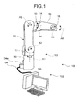
FIG. 1 is a schematic diagram illustrating an overall configuration of a robot system according to an embodiment; -
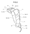
FIG. 2 is a perspective view schematically illustrating an appearance configuration of a robot according to the embodiment; -
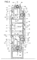
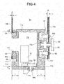
FIG. 3 ,FIG. 4 , andFIG. 6 are schematic cross-sectional views for explaining a partial configuration of the robot according to the embodiment; and -
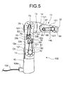
FIG. 5 is a schematic perspective view illustrating a state where covers of the robot according to the embodiment are removed. - Hereinafter, an embodiment is explained.
As shown inFIG. 1 , arobot system 100 according to the embodiment includes arobot 101 and acontroller 102.
Therobot 101 includes abase 10, afirst structure 11, asecond structure 12, athird structure 13, afourth structure 14, afifth structure 15, and asixth structure 16 as structures in the order from an installation surface 103 (base end) to the tip end of therobot 101.
In the lower portion of thebase 10, acable connector 104a for connecting acable 104 is connected, and thecable 104 is connected to thecontroller 102 and a not-shown power supply. - In the present embodiment, a general-purpose computer is applied as the
controller 102 for configuring at a lower cost, and an operation of each actuator to be described later mounted on therobot 101 is controlled based on an instruction from thecontroller 102.
Thecontroller 102 is not limited to a general-purpose computer and other computing devices, such as a dedicated robot controller and a servo controller may, of course, be used. - The connection configuration of the
structures 10 to 16 and the movable configuration of each of thestructures 10 to 16 are explained. As shown inFIG. 1 andFIG. 2 , thebase 10 is fixed to theinstallation surface 103 with not-shown anchor bolts. Thefirst structure 11 is connected to thebase 10 to be rotatable about a first axis A1 substantially vertical to theinstallation surface 103.
As shown also inFIG. 3 , thesecond structure 12 includes a mainstructural part 12a, an auxiliarystructural part 12b, and aconnection part 12c. The mainstructural part 12a and the auxiliarystructural part 12b are provided with an interval therebetween. Each of the mainstructural part 12a and the auxiliarystructural part 12b is connected to thefirst structure 11 at the base end side to be rotatable about a second axis A2 orthogonal to the first axis A1. Theconnection part 12c is connected to the mainstructural part 12a and the auxiliarystructural part 12b at both ends. - The
third structure 13 is provided on the tip end sides of the mainstructural part 12a and the auxiliarystructural part 12b to be sandwiched between the mainstructural part 12a and the auxiliarystructural part 12b. Thethird structure 13 is connected to each of the mainstructural part 12a and the auxiliarystructural part 12b to be rotatable about a third axis A3 parallel to the second axis A2. - The
fourth structure 14 includes a fourthstructure base part 14a, a firststructural part 14b, and a secondstructural part 14c. Each base end side of the firststructural part 14b and the secondstructural part 14c is connected to the fourthstructure base part 14a to sandwich the fourthstructure base part 14a. - The
fifth structure 15 is provided on the tip end sides of the firststructural part 14b and the secondstructural part 14c to be sandwiched between the firststructural part 14b and the secondstructural part 14c. Thefifth structure 15 is connected to each of the firststructural part 14b and the secondstructural part 14c to be rotatable about a fifth axis A5 orthogonal to the fourth axis A4.
Thesixth structure 16 is connected to thefifth structure 15 to be rotatable about a sixth axis A6 orthogonal to the fifth axis A5.
Thesixth structure 16 is provided with a not-shown engaging portion and various end effectors, such as a gripper and a torch, can be attached via the engaging portion.
As used herein, "orthogonal" is not limited to a mathematical sense and thus is meant to allow a reasonable error. - Each configuration of the
structures 10 to 16 is explained in detail. As shown inFIG. 3 , thebase 10 is integrally molded of a cast material such as metal and ahollow portion 10a capable of storing acable harness 104b is formed in thebase 10.
A firstcylindrical portion 10b projected in a cylindrical shape is formed on the tip end side of thebase 10. On the inner side of the firstcylindrical portion 10b, a secondcylindrical portion 10c concentric with the firstcylindrical portion 10b is formed. Bearing members of aharmonic drive 51 are fit into the inner walls of the firstcylindrical portion 10b and the secondcylindrical portion 10c. - Moreover, as shown in
FIG. 3 andFIG. 4 , thefirst structure 11 is a metal cast material and aspace 11j capable of storing a not-shown distribution cable and anactuator 31 is formed in thefirst structure 11.
Theactuator 31 is composed of, for example, a servo motor arranged in thespace 11j and anoutput shaft 31a thereof meshes with agear 54.
Ashaft 54a of thegear 54 extends along the first axis A1 and is connected to the input portion of theharmonic drive 51.
In other words, thefirst structure 11 rotates about the first axis A1 with respect to thebase 10 via theharmonic drive 51 by rotationally driving theactuator 31. - The shape of the
first structure 11 is explained in more detail. Thefirst structure 11 includes a one-side wall portion 11a with a metal thickness L and an other-side wall portion 11b with a metal thickness l (L>l) facing the one-side wall portion 11a. Moreover, thefirst structure 11 includes abottom portion 11c with a metal thickness H continuous with the one-side wall portion 11a and the other-side wall portion 11b and aceiling portion 11d with a metal thickness h (H>h) that faces thebottom portion 11c and is continuous with the one-side wall portion 11a and the other-side wall portion 11b. As described above, thespace 11j capable of storing thecable harness 104b, theactuator 31, and the like is formed between the one-side wall portion 11a and the other-side wall portion 11b.
Moreover, ahole 11e, through which theshaft 54a of thegear 54 can be inserted, is provided in thebottom portion 11c and the bearing member of theharmonic drive 51 is fit into thishole 11e. Thegear 54 and theshaft 54a are hollow and thecable harness 104b is routed through the hollows from thehollow portion 10a of thebase 10 to thespace 11j of thefirst structure 11. - A
cutout portion 11f cut into a cylindrical shape is formed on the outside (opposite side of thespace 11j) of the one-side wall portion 11a. Acylindrical portion 11g having a concentric cylindrical shape projects on the inner side of the cylindrical shape of thecutout portion 11f.
Bearing members of aharmonic drive 57 are fit into the inner walls of thecutout portion 11f and thecylindrical portion 11g, respectively.
The output portion of theharmonic drive 57 and the mainstructural part 12a of thesecond structure 12 are joined by a plurality ofbolts 62. Ahole 63, into which ashaft 60a of apulley 60 can be inserted, is provided in the mainstructural part 12a and theshaft 60a is connected to the input portion of theharmonic drive 57. - In the other-
side wall portion 11b, a thinnedrecess portion 11i is formed and abearing hole 11h, which projects in a cylindrical shape from therecess portion 11i and through which thespace 11j communicates with the outside, is formed.
A bearingmember 55 is attached to the outside of thebearing hole 11h and a metallic thickauxiliary member 56 having a ring (cylindrical) shape is attached to the outside of the bearingmember 55.
The auxiliarystructural part 12b of thesecond structure 12 is joined to the thickauxiliary member 56. More specifically, a ring-shapedcutout portion 56a is provided in the thickauxiliary member 56 and aconnection hole 64 for connection corresponding to the shape of thecutout portion 56a is provided in the auxiliarystructural part 12b. Thecutout portion 56a is fit into theconnection hole 64 and adhesive is applied between thecutout portion 56a and theconnection hole 64. In other words, thecutout portion 56a and theconnection hole 64 are bonded to each other without welding.
Therefore, the mainstructural part 12a and the auxiliarystructural part 12b rotate about the second axis A2 with respect to thefirst structure 11 via theharmonic drive 57 by rotationally driving anactuator 32. - The main
structural part 12a of thesecond structure 12 is formed of a steel plate (rolled steel plate in the present embodiment) as a standard product and has a thickness (thickness length) D in a plate thickness direction. On the other hand, the auxiliarystructural part 12b is also a rolled steel plate that is a standard product in the similar manner to the mainstructural part 12a, however, has a length d (D>d) in a plate thickness direction. The mainstructural part 12a and the auxiliarystructural part 12b are provided to extend in parallel from thefirst structure 11 to thethird structure 13 and a gap S1 is present between the mainstructural part 12a and the auxiliarystructural part 12b.
As shown inFIG. 5 , a plurality ofcover bases 121 is attached to the outer surfaces (surfaces on the opposite side of the gap S1) of the mainstructural part 12a and the auxiliarystructural part 12b and resin covers C1 and C2 are attached to the cover bases 121 of the mainstructural part 12a and the auxiliarystructural part 12b, respectively. - Beam members (
beam members 65 and 66) are provided as structural reinforcement members formed of steel pipes or the like on the base end side and the tip end side, respectively, between the mainstructural part 12a and the auxiliarystructural part 12b.
In the mainstructural part 12a, ahole 67, into which theactuator 32 can be inserted, is provided and ahole 68, into which anactuator 33 can be inserted, is provided distal to thehole 67. Both theholes beam member 65 and proximal to thebeam member 66. - The
actuator 32 is fit into thehole 67 of the mainstructural part 12a and is fixed to the mainstructural part 12a bybolts 32b as shown inFIG. 5 . Apulley 69 is attached near the tip end of anoutput shaft 32a of theactuator 32. Theactuator 33 is fit into thehole 68 of the mainstructural part 12a and is fixed to the mainstructural part 12a bybolts 33b. Apulley 70 is attached near the tip end of anoutput shaft 33a of theactuator 33. - The
pulley 69 and thepulley 60 are connected by a belt B1 to be able to transmit a torque and the drive force of theactuator 32 can be transmitted to thepulley 60 via the belt B1. Thepulley 70 and apulley 73 are connected by a belt B2 to be able to transmit a torque and the drive force of theactuator 33 can be transmitted to thepulley 73 via the belt B2. - Cable communication holes 71 and 72, through which the
cable harness 104b and the like can communicate, are provided in the auxiliarystructural part 12b. Both the two cable communication holes 71 and 72 are provided distal to thebeam member 65 and proximal to thebeam member 66.
A resin cover C3, which covers thebeam members actuators actuators - The
third structure 13 is a cast material integrally molded of molten metal to have the same shape as thefirst structure 11. However, thethird structure 13 is attached upside-down with respect to thefirst structure 11.
In other words, in the similar manner to thefirst structure 11, thethird structure 13 includes aspace 13j capable of storing thecable harness 104b and an actuator. Moreover, thethird structure 13 includes a one-side wall portion 13a with a metal thickness L and an other-side wall portion 13b with a metal thickness l (L>l) facing the one-side wall portion 13a. Furthermore, thethird structure 13 includes abottom portion 13c with a metal thickness H continuous with the one-side wall portion 13a and the other-side wall portion 13b and aceiling portion 13d with a metal thickness h (H>h) that faces thebottom portion 13c and is continuous with the one-side wall portion 13a and the other-side wall portion 13b. - A
cutout portion 13f cut into a cylindrical shape is formed on the outside (opposite side of thespace 13j) of the one-side wall portion 13a. Acylindrical portion 13g having a cylindrical shape, whose center axis is the same as thecutout portion 13f, projects on the inner side of the cylindrical shape of thecutout portion 13f.
Bearing members of aharmonic drive 74 are fit into the inner walls of thecutout portion 13f and thecylindrical portion 13g, respectively. - The main
structural part 12a of thesecond structure 12 is joined to the output portion of theharmonic drive 74 by a plurality ofbolts 78. Ahole 79, into which ashaft 73a of thepulley 73 can be inserted, is provided in the mainstructural part 12a and theshaft 73a is connected to the input portion of theharmonic drive 74.
Therefore, thethird structure 13 rotates about the third axis A3 with respect to the mainstructural part 12a and the auxiliarystructural part 12b via theharmonic drive 74 by rotationally driving theactuator 33. - In the other-
side wall portion 13b, a thinnedrecess portion 13i is formed and abearing hole 13h, which projects in a cylindrical shape from therecess portion 13i and through which thespace 13j communicates with the outside, is formed.
A bearingmember 80 is attached to the outside of thebearing hole 13h and a metallic thickauxiliary member 81 having a ring (cylindrical) shape is attached to the outside of the bearingmember 80. - A ring-shaped
cutout portion 81a is provided in the thickauxiliary member 81 and aconnection hole 82 for connection corresponding to the shape of thecutout portion 81a is provided in the auxiliarystructural part 12b. Thecutout portion 81a is fit into theconnection hole 82 and adhesive is applied between thecutout portion 81a and theconnection hole 82, so that thecutout portion 81a and theconnection hole 82 are bonded to each other without welding.
Moreover, ahole 13e, through which ashaft 83a of agear 83 can be inserted, is provided in thebottom portion 13c and the bearing member of aharmonic drive 84 is fit into thishole 13e.
Anactuator 34 is composed of, for example, a servo motor arranged in thespace 13j and anoutput shaft 34a thereof meshes with thegear 83. - As shown in
FIG. 6 , thefourth structure 14 includes the fourthstructure base part 14a formed of a metal cast material, and the firststructural part 14b and the secondstructural part 14c joined to the fourthstructure base part 14a by a plurality ofbolts 85. - A
space 14d capable of storing thecable harness 104b and acylindrical portion 14e cut into a cylindrical shape are formed in the fourthstructure base part 14a and the bearing member of theharmonic drive 84 is fit into the inner wall side of thecylindrical portion 14e.
Thegear 83 and theshaft 83a are hollow and thecable harness 104b is routed through the hollow portions from thespace 13j to thespace 14d of the fourthstructure base part 14a.
Therefore, thefourth structure 14 rotates about the fourth axis A4 with respect to thethird structure 13 via theharmonic drive 84 by rotationally driving theactuator 34. - The first
structural part 14b and the secondstructural part 14c are formed of rolled steel plates that are standard products having the same plate thickness, and the plate thickness (thickness length) thereof is set smaller than the plate thickness D of the mainstructural part 12a of thesecond structure 12.
The firststructural part 14b and the secondstructural part 14c are provided to extend in parallel from the fourthstructure base part 14a to thefifth structure 15 and a gap S2 is present between the firststructural part 14b and the secondstructural part 14c.
As shown inFIG. 5 , a plurality of the cover bases 121 is attached to the outer surfaces (surfaces on the opposite side of the gap S2) of the firststructural part 14b and the secondstructural part 14c and resin covers C4 and C5 are attached to the cover bases 121 of the firststructural part 14b and the secondstructural part 14c, respectively. - A
beam member 86 is provided as a structural reinforcement member formed of a steel pipe or the like between the firststructural part 14b and the secondstructural part 14c.
Ahole 93, through which thecable harness 104b can communicate, is provided in the secondstructural part 14c.
A resin cover C6, which covers thebeam member 86 and anactuator 35, is attached to the gap S2 to isolate mainly the actuator 35 from outside.
Ahole 87, into which anoutput shaft 35a of theactuator 35 can be inserted, is provided in the firststructural part 14b. Theactuator 35 is fit into thehole 87 of the firststructural part 14b and apulley 88 is attached to the tip end of theoutput shaft 35a.
Moreover, ahole 90, into which ashaft 89a of apulley 89 can be inserted, is provided distal to thehole 87. Thepulley 88 and thepulley 89 are connected by a belt B3 to be able to transmit a torque and the drive force of theactuator 35 can be transmitted to thepulley 89 via the belt B3. - The
fifth structure 15 is formed of a metal cast material and is formed to be smaller and lighter than thefirst structure 11 and thethird structure 13.
In the similar manner to thefirst structure 11 and thethird structure 13, thefifth structure 15 includes aspace 15j capable of storing thecable harness 104b and an actuator.
Thefifth structure 15 includes a one-side wall portion 15a, an other-side wall portion 15b facing the one-side wall portion 15a, aceiling portion 15d continuous with the one-side wall portion 15a and the other-side wall portion 15b, and abottom portion 15c that faces theceiling portion 15d and is continuous with the one-side wall portion 15a and the other-side wall portion 15b. Anactuator 36 is arranged in thespace 15j. Ahole 15e, through which anoutput shaft 36a of theactuator 36 can be inserted, is provided in theceiling portion 15d and acylindrical portion 15k having a cylindrical shape is formed on the outside (opposite side of thespace 15j) of theceiling portion 15d. Bearing members of aharmonic drive 92 are fit into thehole 15e and thecylindrical portion 15k, respectively. The output side of theharmonic drive 92 is connected to the sixth structure (flange) 16 to be integrally rotatable. - A
cutout portion 15f cut into a cylindrical shape is formed on the outside (opposite side of thespace 15j) of the one-side wall portion 15a. Acylindrical portion 15g having a concentric cylindrical shape projects on the inner side of the cylindrical shape of thecutout portion 15f.
The bearing members of theharmonic drive 92 are fit into the inner walls of thecutout portion 15f and thecylindrical portion 15g, respectively, the input portion of theharmonic drive 92 is connected to theshaft 89a of thepulley 89, and the output side of theharmonic drive 92 is connected to the firststructural part 14b by a plurality ofbolts 94.
In other words, thefifth structure 15 rotates about the fifth axis A5 with respect to thefourth structure 14 via theharmonic drive 92 by rotationally driving theactuator 35.
Moreover, thesixth structure 16 rotates about the sixth axis A6 with respect to thefifth structure 15 via theharmonic drive 92 by rotationally driving theactuator 36. - The
sixth structure 16 is formed of steel or the like to have a disk shape and an engaging portion (not shown) capable of attaching an end effector, such as a robot hand, is formed on the surface on the tip end side. - The
robot 101 according to the present embodiment is configured as above, and thefirst structure 11 and thethird structure 13 are formed by using cast materials having the same shape. Therefore, the number of customized parts can be reduced and the cost can be reduced through mass-production of cast materials having the same shape by standardizing parts.
Moreover, in therobot 101 according to the present embodiment, the mainstructural part 12a and the auxiliarystructural part 12b of thesecond structure 12 and the firststructural part 14b and the secondstructural part 14c of thefourth structure 14, which are relatively long, are formed by using a standardized steel plate that can be obtained at a low price. Consequently, the effect of significantly reducing the cost can be expected by dramatically reducing the number of customized parts such as a cast material. - When a standardized steel plate is used as the structural members, advantages, such as providing a rib or a thick portion according to an assumed stress (specially, twist direction or the like), obtained when using customized parts each having an optimized shape cannot be obtained. In regard to this point, in the present embodiment, the main
structural part 12a having a relatively large thickness and the auxiliarystructural part 12b, which is thinner and lighter than the mainstructural part 12a, are used to be arranged in parallel, so that the structural members can be reduced in weight and the rigidity of the structural members in the twist direction can be improved.
Furthermore, in the present embodiment, theactuator 32 and theactuator 33, which are relatively heavy, are arranged to be adjacent to each other in the gap between the mainstructural part 12a and the auxiliarystructural part 12b and are supported only by the mainstructural part 12a. Consequently, the auxiliarystructural part 12b having a smaller thickness can be selected, enabling to further reduce the weight. - On the other hand, in the present embodiment, the thickness of the auxiliary
structural part 12b is set small. Therefore, in terms of insufficient engagement margin between the bearingmember 55 and the auxiliarystructural part 12b, the thickauxiliary member 56 is bonded to the auxiliarystructural part 12b, so that sufficient engagement margin can be ensured between the bearingmember 55 and the auxiliarystructural part 12b. Moreover, in the present embodiment, because the auxiliarystructural part 12b and the thickauxiliary member 56 are bonded only with adhesive without welding or using bolts or the like, man-hours required for joining the auxiliarystructural part 12b and the thickauxiliary member 56 is reduced. Furthermore, because distortion or residual stress due to welding heat is not generated, the auxiliarystructural part 12b can be accurately processed even when the thickness of the auxiliarystructural part 12b is set smaller. In this manner, there is an advantage that a low-cost and highly accurate structure can be formed as long as the load capacity required of therobot 101 is within a range that does not exceed the bonding strength of adhesive. - In the present embodiment, the first structure and the third structure are formed of cast materials having the same shape, however, in addition to the first structure and the third structure, the fifth structure may be also formed by using a cast material having the same shape. At this time, while using a common mold, a structure closer to the tip end side may be formed by using a material having a specific gravity smaller than that of a structure closer to the base end side. For example, the first structure and the third structure may be molded using molds having the same shape, the first structure may be formed by using a material having a relatively high rigidity, and the third structure may be formed by using a material that has a relatively low rigidity and is light compared with the first structure.
- Moreover, in the present embodiment, the main structural part and the auxiliary structural part, which are rolled steel plate materials having different thicknesses, are provided as the second structure, however, the main structural part and the auxiliary structural part may be formed of rolled steel plate materials having the same thickness.
Moreover, as a material of a steel plate, various metal steel plates, such as steel, aluminum, and stainless steel may be applied.
Claims (9)
- A robot (101) comprising:a base (10);a first structure (11) connected to the base (10) to be rotatable about a first axis (A1);a second structure (12) connected to the first structure (11) to be rotatable about a second axis (A2) orthogonal to the first axis (A1); anda third structure (13) connected to the second structure (12) to be rotatable about a third axis (A3) parallel to the second axis (A2), whereinthe first structure (11) and the third structure (13) are formed by using cast materials having a same shape.
- The robot (101) according to claim 1, wherein
each of the first structure (11) and the third structure (13) includes
a one-side wall portion (11a, 13a),
an other-side wall portion (11b, 13b) having a thickness smaller than the one-side wall portion (11a, 13a),
a space (11j, 13j) formed between the one-side wall portion (11a, 13a) and the other-side wall portion (11b, 13b),
a cutout portion (11f, 13f) formed into a cylindrical shape in the one-side wall portion (11a, 13a), and
a bearing hole (11h, 13h) that is formed into a cylindrical shape in the other-side wall portion (11b, 13b) and communicates with the space (11j, 13j). - The robot (101) according to claim 1 or 2, wherein the second structure (12) includes
a main structural part (12a) that is formed of a steel plate, and is supported to be rotatable about the second axis (A2) at a base end and is supported to be rotatable about the third axis (A3) at a tip end, and
an auxiliary structural part (12b) that is formed of a steel plate having a smaller plate thickness than the main structural part (12a) and is provided to have a gap (S1) from the main structural part (12a), and is supported to be rotatable about the second axis (A2) at a base end and is supported to be rotatable about the third axis (A3) at a tip end. - The robot (101) according to claim 3, further comprising at least one actuator (32, 33) whose output shaft (32a, 33a) penetrates through the main structural part (12a) and is supported by the main structural part (12a) and which is arranged in the gap (S1) between the main structural part (12a) and the auxiliary structural part (12b).
- The robot (101) according to claim 4, wherein
a second axis actuator (32) and a third axis actuator (33) are arranged in the gap (S1) between the main structural part (12a) and the auxiliary structural part (12b), as the actuator (32, 33), and
the robot (101) further includes
a second axis power transmission mechanism (60, 69, B1, 57) capable of performing power transmission between an output shaft (32a) of the second axis actuator (32), which penetrates through the main structural part (12a), and the first structure (11), and
a third axis power transmission mechanism (70, 73, B2, 74) capable of performing power transmission between an output shaft (33a) of the third axis actuator (33), which penetrates through the main structural part (12a), and the third structure (13). - The robot (101) according to any one of claims 3 to 5, further comprising:a bearing member (55) that rotatably supports the auxiliary structural part (12b) and the first structure (11); anda thick auxiliary member (56) that is interposed between the bearing member (55) and the auxiliary structural part (12b) and compensates for a length of the auxiliary structural part (12b) in a plate thickness direction.
- The robot (101) according to any one of claims 3 to 6, further comprising:a bearing member (80) that rotatably supports the auxiliary structural part (12b) and the third structure (13); anda thick auxiliary member (81) that is interposed between the bearing member (80) and the auxiliary structural part (12b) and compensates for a length of the auxiliary structural part (12b) in a plate thickness direction.
- The robot (101) according to claim 6 or 7, wherein
a connection hole (64, 82) for connecting the bearing member is formed in the auxiliary structural part (12b),
the thick auxiliary member (56, 81) includes a cutout portion (56a, 81a) matching the connection hole (64, 82), and
the connection hole (64, 82) of the auxiliary structural part (12b) and the cutout portion (56a, 81a) of the thick auxiliary member (56, 81) are bonded with adhesive. - The robot (101) according to any one of claims 1 to 8, further comprising:a fourth structure (14) connected to the third structure (13) to be rotatable about a fourth axis (A4) orthogonal to the third axis (A3);a fifth structure (15) connected to the fourth structure (14) to be rotatable about a fifth axis (A5) orthogonal to the fourth axis (A4); anda sixth structure (16) connected to the fifth structure (15) to be rotatable about a sixth axis (A6) orthogonal to the fifth axis (A5).
Applications Claiming Priority (1)
| Application Number | Priority Date | Filing Date | Title |
|---|---|---|---|
| JP2011023082A JP5299444B2 (en) | 2011-02-04 | 2011-02-04 | robot |
Publications (2)
| Publication Number | Publication Date |
|---|---|
| EP2484496A1 true EP2484496A1 (en) | 2012-08-08 |
| EP2484496B1 EP2484496B1 (en) | 2014-05-14 |
Family
ID=45540778
Family Applications (1)
| Application Number | Title | Priority Date | Filing Date |
|---|---|---|---|
| EP20120150031 Active EP2484496B1 (en) | 2011-02-04 | 2012-01-03 | Robot |
Country Status (4)
| Country | Link |
|---|---|
| US (1) | US8910538B2 (en) |
| EP (1) | EP2484496B1 (en) |
| JP (1) | JP5299444B2 (en) |
| CN (1) | CN102626931B (en) |
Cited By (2)
| Publication number | Priority date | Publication date | Assignee | Title |
|---|---|---|---|---|
| EP2808132A1 (en) * | 2013-05-20 | 2014-12-03 | Kabushiki Kaisha Yaskawa Denki | Connection member, manufacturing method of connection member, and robot |
| EP3189946A1 (en) * | 2016-01-08 | 2017-07-12 | ABB Schweiz AG | An industrial robot with a modular lower arm |
Families Citing this family (22)
| Publication number | Priority date | Publication date | Assignee | Title |
|---|---|---|---|---|
| KR101438513B1 (en) * | 2013-01-24 | 2014-09-12 | 한국원자력연구원 | Actuator module of two-far-end supported for snake robots using inside wiring |
| CN103568002B (en) * | 2013-06-25 | 2015-09-09 | 雷跃峰 | Six axle free degree manipulators |
| CN103331752A (en) * | 2013-07-04 | 2013-10-02 | 太原重工股份有限公司 | Hydraulic drive mechanical arm |
| US20150283709A1 (en) * | 2014-04-08 | 2015-10-08 | Sergei Dalakian | Industrial Robot Arm |
| JP6326945B2 (en) * | 2014-05-07 | 2018-05-23 | セイコーエプソン株式会社 | robot |
| JP2016068204A (en) | 2014-09-30 | 2016-05-09 | セイコーエプソン株式会社 | robot |
| CN104875195A (en) * | 2015-06-09 | 2015-09-02 | 北华航天工业学院 | Manipulator |
| US10718359B2 (en) * | 2015-08-21 | 2020-07-21 | Quality Manufacturing Inc. | Devices and systems for producing rotational actuation |
| JP6605432B2 (en) * | 2016-12-07 | 2019-11-13 | 株式会社神戸製鋼所 | Industrial robot |
| IT201600130715A1 (en) * | 2016-12-23 | 2018-06-23 | Comau Spa | "Functional device, in particular robots, with modular modules for educational use" |
| CN107234629B (en) * | 2017-04-18 | 2021-04-13 | 昆山奥迪尔智能科技有限公司 | A multi-axis robot |
| US10022861B1 (en) | 2017-04-27 | 2018-07-17 | Engineering Services Inc. | Two joint module and arm using same |
| JP6988152B2 (en) * | 2017-05-08 | 2022-01-05 | セイコーエプソン株式会社 | robot |
| JP6730362B2 (en) * | 2018-04-11 | 2020-07-29 | ファナック株式会社 | Robot wrist structure |
| JP6882229B2 (en) * | 2018-05-09 | 2021-06-02 | ファナック株式会社 | Link components for robots and robots |
| JP6875348B2 (en) * | 2018-10-17 | 2021-05-26 | ファナック株式会社 | Robot and 1st arm member |
| CN110074731A (en) * | 2019-04-28 | 2019-08-02 | 哈尔滨工程大学 | A kind of ground sundries cleaning storage robot |
| DE102023120473A1 (en) * | 2022-09-07 | 2024-03-07 | Kabushiki Kaisha Yaskawa Denki | robot |
| DE102023115330B4 (en) * | 2023-06-13 | 2025-03-06 | Iav Gmbh Ingenieurgesellschaft Auto Und Verkehr | Articulated arm with fork joint for a manipulator of a harvesting machine |
| JP2025085368A (en) | 2023-11-24 | 2025-06-05 | 株式会社安川電機 | robot |
| JP2025085365A (en) | 2023-11-24 | 2025-06-05 | 株式会社安川電機 | robot |
| JP2025085362A (en) | 2023-11-24 | 2025-06-05 | 株式会社安川電機 | robot |
Citations (4)
| Publication number | Priority date | Publication date | Assignee | Title |
|---|---|---|---|---|
| US5293107A (en) * | 1993-02-24 | 1994-03-08 | Fanuc Robotics North America, Inc. | Motorized rotary joint and method of constructing a modular robot utilizing same |
| DE19509050A1 (en) * | 1995-03-14 | 1996-09-19 | Hesse Gmbh | Industrial assembly or handling etc. robot |
| JP2006055936A (en) | 2004-08-19 | 2006-03-02 | Kondo Seisakusho:Kk | Industrial robot |
| EP1930129A1 (en) * | 2005-09-27 | 2008-06-11 | Kabushiki Kaisha Yaskawa Denki | Multi-joint manipulator |
Family Cites Families (11)
| Publication number | Priority date | Publication date | Assignee | Title |
|---|---|---|---|---|
| JPS6114889A (en) * | 1984-06-29 | 1986-01-23 | フアナツク株式会社 | Electric type industrial robot having inner-pressure explosion-proof structure |
| JPS5973297A (en) * | 1982-10-20 | 1984-04-25 | フアナツク株式会社 | Wrist mechanism of industrial robot |
| JP2919172B2 (en) * | 1992-04-28 | 1999-07-12 | ファナック株式会社 | Industrial robot cable processing equipment |
| JP2003275977A (en) * | 2002-03-20 | 2003-09-30 | Yamaha Motor Co Ltd | SCARA robot |
| SE0202445L (en) * | 2002-08-19 | 2004-02-20 | Abb Ab | Device at an industrial robot |
| JP2007069798A (en) * | 2005-09-08 | 2007-03-22 | Shimano Inc | Crank assembly for bicycle |
| JP4847744B2 (en) * | 2005-11-30 | 2011-12-28 | 株式会社ニッセイ | Orthogonal axis reducer with motor, orthogonal axis reducer, and joint structure of robot |
| JP5177835B2 (en) * | 2007-04-27 | 2013-04-10 | 株式会社安川電機 | Double-arm robot manipulator |
| JP2010094749A (en) * | 2008-10-14 | 2010-04-30 | Yaskawa Electric Corp | Articulated robot and robot system |
| CN102049783A (en) * | 2009-11-10 | 2011-05-11 | 鸿富锦精密工业(深圳)有限公司 | Robot structure |
| JP2012223849A (en) * | 2011-04-19 | 2012-11-15 | Yaskawa Electric Corp | Robot |
-
2011
- 2011-02-04 JP JP2011023082A patent/JP5299444B2/en active Active
-
2012
- 2012-01-03 EP EP20120150031 patent/EP2484496B1/en active Active
- 2012-01-04 CN CN201210001138.4A patent/CN102626931B/en active Active
- 2012-01-27 US US13/359,503 patent/US8910538B2/en active Active
Patent Citations (4)
| Publication number | Priority date | Publication date | Assignee | Title |
|---|---|---|---|---|
| US5293107A (en) * | 1993-02-24 | 1994-03-08 | Fanuc Robotics North America, Inc. | Motorized rotary joint and method of constructing a modular robot utilizing same |
| DE19509050A1 (en) * | 1995-03-14 | 1996-09-19 | Hesse Gmbh | Industrial assembly or handling etc. robot |
| JP2006055936A (en) | 2004-08-19 | 2006-03-02 | Kondo Seisakusho:Kk | Industrial robot |
| EP1930129A1 (en) * | 2005-09-27 | 2008-06-11 | Kabushiki Kaisha Yaskawa Denki | Multi-joint manipulator |
Non-Patent Citations (2)
| Title |
|---|
| KUKA ROBOTER GMBH: "Robots KR 1000 titan, KR 1000 L750 with "F" variants - Specification", 16 November 2010 (2010-11-16), XP002670134, Retrieved from the Internet <URL:http://www.kuka-robotics.com/res/sps/e6c77545-9030-49b1-93f5-4d17c92173aa_Spez_KR_1000_titan_en.pdf> [retrieved on 20120222] * |
| KUKA ROBOTER GMBH: "Specification - Robots KR 6, KR 16, KR 16 L6, KR 16 S", 9 June 2003 (2003-06-09), XP002670135, Retrieved from the Internet <URL:http://www.kuka-robotics.com/res/sps/e6c77545-9030-49b1-93f5-4d17c92173aa_Spez_KR_16_en.pdf> [retrieved on 20120222] * |
Cited By (2)
| Publication number | Priority date | Publication date | Assignee | Title |
|---|---|---|---|---|
| EP2808132A1 (en) * | 2013-05-20 | 2014-12-03 | Kabushiki Kaisha Yaskawa Denki | Connection member, manufacturing method of connection member, and robot |
| EP3189946A1 (en) * | 2016-01-08 | 2017-07-12 | ABB Schweiz AG | An industrial robot with a modular lower arm |
Also Published As
| Publication number | Publication date |
|---|---|
| JP5299444B2 (en) | 2013-09-25 |
| JP2012161868A (en) | 2012-08-30 |
| US20120198955A1 (en) | 2012-08-09 |
| EP2484496B1 (en) | 2014-05-14 |
| CN102626931B (en) | 2015-05-20 |
| US8910538B2 (en) | 2014-12-16 |
| CN102626931A (en) | 2012-08-08 |
Similar Documents
| Publication | Publication Date | Title |
|---|---|---|
| EP2484496B1 (en) | Robot | |
| JP6650217B2 (en) | Two-stage tacking | |
| US10173327B2 (en) | Device for use in the handling of a load and method for producing such a device | |
| US9272415B2 (en) | Robot device | |
| US20140137687A1 (en) | Robot | |
| US20120216650A1 (en) | Articulated robot wrist | |
| US9701027B2 (en) | Robot | |
| EP2808132B1 (en) | Connection member, manufacturing method of connection member, and robot | |
| JP5217482B2 (en) | Joint structure of fiber reinforced plastic link structure | |
| JP2009190149A (en) | Fiber reinforced plastic link structure | |
| JP5545379B2 (en) | robot | |
| JP2021121529A (en) | Longitudinal beam joint for pressure deck assembly | |
| JP2010179386A (en) | Link structure | |
| US20140137686A1 (en) | Robot | |
| CN220389440U (en) | Modular robot for plane transfer | |
| JP7414992B2 (en) | robot equipment | |
| JP2010076071A (en) | Method for fixing link structure before machining, and method for manufacturing link structure using the same, and link structure | |
| EP2653734A1 (en) | Bolt joint structure | |
| CN220699650U (en) | Joint structure and robot | |
| CA2896059C (en) | Two-stage riveting | |
| US20240272026A1 (en) | Sensor, apparatus, system, and manufacturing method for product | |
| JP2024075510A (en) | Connection plate | |
| CA2895739A1 (en) | Wheel mounting system |
Legal Events
| Date | Code | Title | Description |
|---|---|---|---|
| PUAI | Public reference made under article 153(3) epc to a published international application that has entered the european phase |
Free format text: ORIGINAL CODE: 0009012 |
|
| AK | Designated contracting states |
Kind code of ref document: A1 Designated state(s): AL AT BE BG CH CY CZ DE DK EE ES FI FR GB GR HR HU IE IS IT LI LT LU LV MC MK MT NL NO PL PT RO RS SE SI SK SM TR |
|
| AX | Request for extension of the european patent |
Extension state: BA ME |
|
| 17P | Request for examination filed |
Effective date: 20121221 |
|
| 17Q | First examination report despatched |
Effective date: 20130130 |
|
| GRAP | Despatch of communication of intention to grant a patent |
Free format text: ORIGINAL CODE: EPIDOSNIGR1 |
|
| INTG | Intention to grant announced |
Effective date: 20140108 |
|
| GRAS | Grant fee paid |
Free format text: ORIGINAL CODE: EPIDOSNIGR3 |
|
| GRAA | (expected) grant |
Free format text: ORIGINAL CODE: 0009210 |
|
| AK | Designated contracting states |
Kind code of ref document: B1 Designated state(s): AL AT BE BG CH CY CZ DE DK EE ES FI FR GB GR HR HU IE IS IT LI LT LU LV MC MK MT NL NO PL PT RO RS SE SI SK SM TR |
|
| REG | Reference to a national code |
Ref country code: GB Ref legal event code: FG4D |
|
| REG | Reference to a national code |
Ref country code: AT Ref legal event code: REF Ref document number: 667883 Country of ref document: AT Kind code of ref document: T Effective date: 20140615 |
|
| REG | Reference to a national code |
Ref country code: DE Ref legal event code: R096 Ref document number: 602012001604 Country of ref document: DE Effective date: 20140618 Ref country code: IE Ref legal event code: FG4D |
|
| REG | Reference to a national code |
Ref country code: SE Ref legal event code: TRGR |
|
| REG | Reference to a national code |
Ref country code: NL Ref legal event code: VDEP Effective date: 20140514 Ref country code: AT Ref legal event code: MK05 Ref document number: 667883 Country of ref document: AT Kind code of ref document: T Effective date: 20140514 |
|
| REG | Reference to a national code |
Ref country code: LT Ref legal event code: MG4D |
|
| PG25 | Lapsed in a contracting state [announced via postgrant information from national office to epo] |
Ref country code: LT Free format text: LAPSE BECAUSE OF FAILURE TO SUBMIT A TRANSLATION OF THE DESCRIPTION OR TO PAY THE FEE WITHIN THE PRESCRIBED TIME-LIMIT Effective date: 20140514 Ref country code: IS Free format text: LAPSE BECAUSE OF FAILURE TO SUBMIT A TRANSLATION OF THE DESCRIPTION OR TO PAY THE FEE WITHIN THE PRESCRIBED TIME-LIMIT Effective date: 20140914 Ref country code: CY Free format text: LAPSE BECAUSE OF FAILURE TO SUBMIT A TRANSLATION OF THE DESCRIPTION OR TO PAY THE FEE WITHIN THE PRESCRIBED TIME-LIMIT Effective date: 20140514 Ref country code: NO Free format text: LAPSE BECAUSE OF FAILURE TO SUBMIT A TRANSLATION OF THE DESCRIPTION OR TO PAY THE FEE WITHIN THE PRESCRIBED TIME-LIMIT Effective date: 20140814 Ref country code: FI Free format text: LAPSE BECAUSE OF FAILURE TO SUBMIT A TRANSLATION OF THE DESCRIPTION OR TO PAY THE FEE WITHIN THE PRESCRIBED TIME-LIMIT Effective date: 20140514 Ref country code: GR Free format text: LAPSE BECAUSE OF FAILURE TO SUBMIT A TRANSLATION OF THE DESCRIPTION OR TO PAY THE FEE WITHIN THE PRESCRIBED TIME-LIMIT Effective date: 20140815 |
|
| PG25 | Lapsed in a contracting state [announced via postgrant information from national office to epo] |
Ref country code: AT Free format text: LAPSE BECAUSE OF FAILURE TO SUBMIT A TRANSLATION OF THE DESCRIPTION OR TO PAY THE FEE WITHIN THE PRESCRIBED TIME-LIMIT Effective date: 20140514 Ref country code: PL Free format text: LAPSE BECAUSE OF FAILURE TO SUBMIT A TRANSLATION OF THE DESCRIPTION OR TO PAY THE FEE WITHIN THE PRESCRIBED TIME-LIMIT Effective date: 20140514 Ref country code: RS Free format text: LAPSE BECAUSE OF FAILURE TO SUBMIT A TRANSLATION OF THE DESCRIPTION OR TO PAY THE FEE WITHIN THE PRESCRIBED TIME-LIMIT Effective date: 20140514 Ref country code: LV Free format text: LAPSE BECAUSE OF FAILURE TO SUBMIT A TRANSLATION OF THE DESCRIPTION OR TO PAY THE FEE WITHIN THE PRESCRIBED TIME-LIMIT Effective date: 20140514 Ref country code: ES Free format text: LAPSE BECAUSE OF FAILURE TO SUBMIT A TRANSLATION OF THE DESCRIPTION OR TO PAY THE FEE WITHIN THE PRESCRIBED TIME-LIMIT Effective date: 20140514 Ref country code: HR Free format text: LAPSE BECAUSE OF FAILURE TO SUBMIT A TRANSLATION OF THE DESCRIPTION OR TO PAY THE FEE WITHIN THE PRESCRIBED TIME-LIMIT Effective date: 20140514 |
|
| PG25 | Lapsed in a contracting state [announced via postgrant information from national office to epo] |
Ref country code: PT Free format text: LAPSE BECAUSE OF FAILURE TO SUBMIT A TRANSLATION OF THE DESCRIPTION OR TO PAY THE FEE WITHIN THE PRESCRIBED TIME-LIMIT Effective date: 20140915 |
|
| PG25 | Lapsed in a contracting state [announced via postgrant information from national office to epo] |
Ref country code: SK Free format text: LAPSE BECAUSE OF FAILURE TO SUBMIT A TRANSLATION OF THE DESCRIPTION OR TO PAY THE FEE WITHIN THE PRESCRIBED TIME-LIMIT Effective date: 20140514 Ref country code: DK Free format text: LAPSE BECAUSE OF FAILURE TO SUBMIT A TRANSLATION OF THE DESCRIPTION OR TO PAY THE FEE WITHIN THE PRESCRIBED TIME-LIMIT Effective date: 20140514 Ref country code: EE Free format text: LAPSE BECAUSE OF FAILURE TO SUBMIT A TRANSLATION OF THE DESCRIPTION OR TO PAY THE FEE WITHIN THE PRESCRIBED TIME-LIMIT Effective date: 20140514 Ref country code: CZ Free format text: LAPSE BECAUSE OF FAILURE TO SUBMIT A TRANSLATION OF THE DESCRIPTION OR TO PAY THE FEE WITHIN THE PRESCRIBED TIME-LIMIT Effective date: 20140514 Ref country code: RO Free format text: LAPSE BECAUSE OF FAILURE TO SUBMIT A TRANSLATION OF THE DESCRIPTION OR TO PAY THE FEE WITHIN THE PRESCRIBED TIME-LIMIT Effective date: 20140514 Ref country code: BE Free format text: LAPSE BECAUSE OF FAILURE TO SUBMIT A TRANSLATION OF THE DESCRIPTION OR TO PAY THE FEE WITHIN THE PRESCRIBED TIME-LIMIT Effective date: 20140514 |
|
| REG | Reference to a national code |
Ref country code: DE Ref legal event code: R097 Ref document number: 602012001604 Country of ref document: DE |
|
| PG25 | Lapsed in a contracting state [announced via postgrant information from national office to epo] |
Ref country code: NL Free format text: LAPSE BECAUSE OF FAILURE TO SUBMIT A TRANSLATION OF THE DESCRIPTION OR TO PAY THE FEE WITHIN THE PRESCRIBED TIME-LIMIT Effective date: 20140514 |
|
| PLBE | No opposition filed within time limit |
Free format text: ORIGINAL CODE: 0009261 |
|
| STAA | Information on the status of an ep patent application or granted ep patent |
Free format text: STATUS: NO OPPOSITION FILED WITHIN TIME LIMIT |
|
| 26N | No opposition filed |
Effective date: 20150217 |
|
| PG25 | Lapsed in a contracting state [announced via postgrant information from national office to epo] |
Ref country code: IT Free format text: LAPSE BECAUSE OF FAILURE TO SUBMIT A TRANSLATION OF THE DESCRIPTION OR TO PAY THE FEE WITHIN THE PRESCRIBED TIME-LIMIT Effective date: 20140514 |
|
| REG | Reference to a national code |
Ref country code: DE Ref legal event code: R097 Ref document number: 602012001604 Country of ref document: DE Effective date: 20150217 |
|
| PG25 | Lapsed in a contracting state [announced via postgrant information from national office to epo] |
Ref country code: SI Free format text: LAPSE BECAUSE OF FAILURE TO SUBMIT A TRANSLATION OF THE DESCRIPTION OR TO PAY THE FEE WITHIN THE PRESCRIBED TIME-LIMIT Effective date: 20140514 |
|
| REG | Reference to a national code |
Ref country code: CH Ref legal event code: PL |
|
| PG25 | Lapsed in a contracting state [announced via postgrant information from national office to epo] |
Ref country code: LU Free format text: LAPSE BECAUSE OF FAILURE TO SUBMIT A TRANSLATION OF THE DESCRIPTION OR TO PAY THE FEE WITHIN THE PRESCRIBED TIME-LIMIT Effective date: 20150103 |
|
| PG25 | Lapsed in a contracting state [announced via postgrant information from national office to epo] |
Ref country code: MC Free format text: LAPSE BECAUSE OF FAILURE TO SUBMIT A TRANSLATION OF THE DESCRIPTION OR TO PAY THE FEE WITHIN THE PRESCRIBED TIME-LIMIT Effective date: 20140514 |
|
| PG25 | Lapsed in a contracting state [announced via postgrant information from national office to epo] |
Ref country code: CH Free format text: LAPSE BECAUSE OF NON-PAYMENT OF DUE FEES Effective date: 20150131 Ref country code: LI Free format text: LAPSE BECAUSE OF NON-PAYMENT OF DUE FEES Effective date: 20150131 |
|
| REG | Reference to a national code |
Ref country code: FR Ref legal event code: ST Effective date: 20150930 |
|
| REG | Reference to a national code |
Ref country code: IE Ref legal event code: MM4A |
|
| PG25 | Lapsed in a contracting state [announced via postgrant information from national office to epo] |
Ref country code: FR Free format text: LAPSE BECAUSE OF NON-PAYMENT OF DUE FEES Effective date: 20150202 |
|
| PG25 | Lapsed in a contracting state [announced via postgrant information from national office to epo] |
Ref country code: IE Free format text: LAPSE BECAUSE OF NON-PAYMENT OF DUE FEES Effective date: 20150103 |
|
| PGFP | Annual fee paid to national office [announced via postgrant information from national office to epo] |
Ref country code: SE Payment date: 20160127 Year of fee payment: 5 |
|
| GBPC | Gb: european patent ceased through non-payment of renewal fee |
Effective date: 20160103 |
|
| PG25 | Lapsed in a contracting state [announced via postgrant information from national office to epo] |
Ref country code: GB Free format text: LAPSE BECAUSE OF NON-PAYMENT OF DUE FEES Effective date: 20160103 |
|
| PG25 | Lapsed in a contracting state [announced via postgrant information from national office to epo] |
Ref country code: MT Free format text: LAPSE BECAUSE OF FAILURE TO SUBMIT A TRANSLATION OF THE DESCRIPTION OR TO PAY THE FEE WITHIN THE PRESCRIBED TIME-LIMIT Effective date: 20140514 |
|
| PG25 | Lapsed in a contracting state [announced via postgrant information from national office to epo] |
Ref country code: BG Free format text: LAPSE BECAUSE OF FAILURE TO SUBMIT A TRANSLATION OF THE DESCRIPTION OR TO PAY THE FEE WITHIN THE PRESCRIBED TIME-LIMIT Effective date: 20140514 Ref country code: SM Free format text: LAPSE BECAUSE OF FAILURE TO SUBMIT A TRANSLATION OF THE DESCRIPTION OR TO PAY THE FEE WITHIN THE PRESCRIBED TIME-LIMIT Effective date: 20140514 Ref country code: HU Free format text: LAPSE BECAUSE OF FAILURE TO SUBMIT A TRANSLATION OF THE DESCRIPTION OR TO PAY THE FEE WITHIN THE PRESCRIBED TIME-LIMIT; INVALID AB INITIO Effective date: 20120103 |
|
| PG25 | Lapsed in a contracting state [announced via postgrant information from national office to epo] |
Ref country code: TR Free format text: LAPSE BECAUSE OF FAILURE TO SUBMIT A TRANSLATION OF THE DESCRIPTION OR TO PAY THE FEE WITHIN THE PRESCRIBED TIME-LIMIT Effective date: 20140514 |
|
| PG25 | Lapsed in a contracting state [announced via postgrant information from national office to epo] |
Ref country code: SE Free format text: LAPSE BECAUSE OF NON-PAYMENT OF DUE FEES Effective date: 20170104 |
|
| PG25 | Lapsed in a contracting state [announced via postgrant information from national office to epo] |
Ref country code: MK Free format text: LAPSE BECAUSE OF FAILURE TO SUBMIT A TRANSLATION OF THE DESCRIPTION OR TO PAY THE FEE WITHIN THE PRESCRIBED TIME-LIMIT Effective date: 20140514 |
|
| PG25 | Lapsed in a contracting state [announced via postgrant information from national office to epo] |
Ref country code: AL Free format text: LAPSE BECAUSE OF FAILURE TO SUBMIT A TRANSLATION OF THE DESCRIPTION OR TO PAY THE FEE WITHIN THE PRESCRIBED TIME-LIMIT Effective date: 20140514 |
|
| PGFP | Annual fee paid to national office [announced via postgrant information from national office to epo] |
Ref country code: DE Payment date: 20251203 Year of fee payment: 15 |