EP2484182B1 - Energy storage based countermeasure for a delayed voltage recovery - Google Patents
Energy storage based countermeasure for a delayed voltage recovery Download PDFInfo
- Publication number
- EP2484182B1 EP2484182B1 EP10819644.5A EP10819644A EP2484182B1 EP 2484182 B1 EP2484182 B1 EP 2484182B1 EP 10819644 A EP10819644 A EP 10819644A EP 2484182 B1 EP2484182 B1 EP 2484182B1
- Authority
- EP
- European Patent Office
- Prior art keywords
- grid
- power source
- electrical
- power
- voltage
- Prior art date
- Legal status (The legal status is an assumption and is not a legal conclusion. Google has not performed a legal analysis and makes no representation as to the accuracy of the status listed.)
- Active
Links
Images


Classifications
-
- H—ELECTRICITY
- H02—GENERATION; CONVERSION OR DISTRIBUTION OF ELECTRIC POWER
- H02J—ELECTRIC POWER NETWORKS; CIRCUIT ARRANGEMENTS OR SYSTEMS FOR SUPPLYING OR DISTRIBUTING ELECTRIC POWER; SYSTEMS FOR STORING ELECTRIC ENERGY
- H02J3/00—Circuit arrangements for AC mains or AC distribution networks
- H02J3/12—Arrangements for adjusting voltage in AC networks by changing a characteristic of the network load
-
- G—PHYSICS
- G01—MEASURING; TESTING
- G01D—MEASURING NOT SPECIALLY ADAPTED FOR A SPECIFIC VARIABLE; ARRANGEMENTS FOR MEASURING TWO OR MORE VARIABLES NOT COVERED IN A SINGLE OTHER SUBCLASS; TARIFF METERING APPARATUS; MEASURING OR TESTING NOT OTHERWISE PROVIDED FOR
- G01D4/00—Tariff metering apparatus
- G01D4/002—Remote reading of utility meters
- G01D4/004—Remote reading of utility meters to a fixed location
-
- H—ELECTRICITY
- H02—GENERATION; CONVERSION OR DISTRIBUTION OF ELECTRIC POWER
- H02J—ELECTRIC POWER NETWORKS; CIRCUIT ARRANGEMENTS OR SYSTEMS FOR SUPPLYING OR DISTRIBUTING ELECTRIC POWER; SYSTEMS FOR STORING ELECTRIC ENERGY
- H02J13/00—Circuit arrangements for providing remote monitoring or remote control of equipment in a power distribution network
- H02J13/13—Circuit arrangements for providing remote monitoring or remote control of equipment in a power distribution network characterised by the transmission of data to equipment in the power network
-
- H—ELECTRICITY
- H02—GENERATION; CONVERSION OR DISTRIBUTION OF ELECTRIC POWER
- H02J—ELECTRIC POWER NETWORKS; CIRCUIT ARRANGEMENTS OR SYSTEMS FOR SUPPLYING OR DISTRIBUTING ELECTRIC POWER; SYSTEMS FOR STORING ELECTRIC ENERGY
- H02J13/00—Circuit arrangements for providing remote monitoring or remote control of equipment in a power distribution network
- H02J13/13—Circuit arrangements for providing remote monitoring or remote control of equipment in a power distribution network characterised by the transmission of data to equipment in the power network
- H02J13/1321—Circuit arrangements for providing remote monitoring or remote control of equipment in a power distribution network characterised by the transmission of data to equipment in the power network using a wired telecommunication network or a data transmission bus
- H02J13/1323—Circuit arrangements for providing remote monitoring or remote control of equipment in a power distribution network characterised by the transmission of data to equipment in the power network using a wired telecommunication network or a data transmission bus using optical fibres
-
- H—ELECTRICITY
- H02—GENERATION; CONVERSION OR DISTRIBUTION OF ELECTRIC POWER
- H02J—ELECTRIC POWER NETWORKS; CIRCUIT ARRANGEMENTS OR SYSTEMS FOR SUPPLYING OR DISTRIBUTING ELECTRIC POWER; SYSTEMS FOR STORING ELECTRIC ENERGY
- H02J13/00—Circuit arrangements for providing remote monitoring or remote control of equipment in a power distribution network
- H02J13/18—Circuit arrangements for providing remote monitoring or remote control of equipment in a power distribution network characterised by the remotely-controlled equipment, e.g. converters or transformers
- H02J13/333—Circuit arrangements for providing remote monitoring or remote control of equipment in a power distribution network characterised by the remotely-controlled equipment, e.g. converters or transformers the equipment forming part of substations
-
- H—ELECTRICITY
- H02—GENERATION; CONVERSION OR DISTRIBUTION OF ELECTRIC POWER
- H02J—ELECTRIC POWER NETWORKS; CIRCUIT ARRANGEMENTS OR SYSTEMS FOR SUPPLYING OR DISTRIBUTING ELECTRIC POWER; SYSTEMS FOR STORING ELECTRIC ENERGY
- H02J3/00—Circuit arrangements for AC mains or AC distribution networks
- H02J3/001—Arrangements for handling faults or abnormalities, e.g. emergencies or contingencies
- H02J3/0012—Arrangements for handling faults or abnormalities, e.g. emergencies or contingencies characterised by the contingency detection means in AC networks, e.g. using phasor measurement units [PMU], synchrophasors or contingency analysis
-
- H—ELECTRICITY
- H02—GENERATION; CONVERSION OR DISTRIBUTION OF ELECTRIC POWER
- H02J—ELECTRIC POWER NETWORKS; CIRCUIT ARRANGEMENTS OR SYSTEMS FOR SUPPLYING OR DISTRIBUTING ELECTRIC POWER; SYSTEMS FOR STORING ELECTRIC ENERGY
- H02J3/00—Circuit arrangements for AC mains or AC distribution networks
- H02J3/001—Arrangements for handling faults or abnormalities, e.g. emergencies or contingencies
- H02J3/00125—Transmission line or load transient problems, e.g. overvoltage, resonance or self-excitation of inductive loads
-
- H—ELECTRICITY
- H02—GENERATION; CONVERSION OR DISTRIBUTION OF ELECTRIC POWER
- H02J—ELECTRIC POWER NETWORKS; CIRCUIT ARRANGEMENTS OR SYSTEMS FOR SUPPLYING OR DISTRIBUTING ELECTRIC POWER; SYSTEMS FOR STORING ELECTRIC ENERGY
- H02J3/00—Circuit arrangements for AC mains or AC distribution networks
- H02J3/28—Arrangements for balancing of the load in networks by storage of energy
- H02J3/32—Arrangements for balancing of the load in networks by storage of energy using batteries or super capacitors with converting means
-
- H—ELECTRICITY
- H02—GENERATION; CONVERSION OR DISTRIBUTION OF ELECTRIC POWER
- H02J—ELECTRIC POWER NETWORKS; CIRCUIT ARRANGEMENTS OR SYSTEMS FOR SUPPLYING OR DISTRIBUTING ELECTRIC POWER; SYSTEMS FOR STORING ELECTRIC ENERGY
- H02J3/00—Circuit arrangements for AC mains or AC distribution networks
- H02J3/18—Arrangements for adjusting, eliminating or compensating reactive power in networks
-
- Y—GENERAL TAGGING OF NEW TECHNOLOGICAL DEVELOPMENTS; GENERAL TAGGING OF CROSS-SECTIONAL TECHNOLOGIES SPANNING OVER SEVERAL SECTIONS OF THE IPC; TECHNICAL SUBJECTS COVERED BY FORMER USPC CROSS-REFERENCE ART COLLECTIONS [XRACs] AND DIGESTS
- Y02—TECHNOLOGIES OR APPLICATIONS FOR MITIGATION OR ADAPTATION AGAINST CLIMATE CHANGE
- Y02B—CLIMATE CHANGE MITIGATION TECHNOLOGIES RELATED TO BUILDINGS, e.g. HOUSING, HOUSE APPLIANCES OR RELATED END-USER APPLICATIONS
- Y02B90/00—Enabling technologies or technologies with a potential or indirect contribution to GHG emissions mitigation
- Y02B90/20—Smart grids as enabling technology in buildings sector
-
- Y—GENERAL TAGGING OF NEW TECHNOLOGICAL DEVELOPMENTS; GENERAL TAGGING OF CROSS-SECTIONAL TECHNOLOGIES SPANNING OVER SEVERAL SECTIONS OF THE IPC; TECHNICAL SUBJECTS COVERED BY FORMER USPC CROSS-REFERENCE ART COLLECTIONS [XRACs] AND DIGESTS
- Y02—TECHNOLOGIES OR APPLICATIONS FOR MITIGATION OR ADAPTATION AGAINST CLIMATE CHANGE
- Y02E—REDUCTION OF GREENHOUSE GAS [GHG] EMISSIONS, RELATED TO ENERGY GENERATION, TRANSMISSION OR DISTRIBUTION
- Y02E40/00—Technologies for an efficient electrical power generation, transmission or distribution
- Y02E40/30—Reactive power compensation
-
- Y—GENERAL TAGGING OF NEW TECHNOLOGICAL DEVELOPMENTS; GENERAL TAGGING OF CROSS-SECTIONAL TECHNOLOGIES SPANNING OVER SEVERAL SECTIONS OF THE IPC; TECHNICAL SUBJECTS COVERED BY FORMER USPC CROSS-REFERENCE ART COLLECTIONS [XRACs] AND DIGESTS
- Y02—TECHNOLOGIES OR APPLICATIONS FOR MITIGATION OR ADAPTATION AGAINST CLIMATE CHANGE
- Y02E—REDUCTION OF GREENHOUSE GAS [GHG] EMISSIONS, RELATED TO ENERGY GENERATION, TRANSMISSION OR DISTRIBUTION
- Y02E40/00—Technologies for an efficient electrical power generation, transmission or distribution
- Y02E40/70—Smart grids as climate change mitigation technology in the energy generation sector
-
- Y—GENERAL TAGGING OF NEW TECHNOLOGICAL DEVELOPMENTS; GENERAL TAGGING OF CROSS-SECTIONAL TECHNOLOGIES SPANNING OVER SEVERAL SECTIONS OF THE IPC; TECHNICAL SUBJECTS COVERED BY FORMER USPC CROSS-REFERENCE ART COLLECTIONS [XRACs] AND DIGESTS
- Y02—TECHNOLOGIES OR APPLICATIONS FOR MITIGATION OR ADAPTATION AGAINST CLIMATE CHANGE
- Y02E—REDUCTION OF GREENHOUSE GAS [GHG] EMISSIONS, RELATED TO ENERGY GENERATION, TRANSMISSION OR DISTRIBUTION
- Y02E60/00—Enabling technologies; Technologies with a potential or indirect contribution to GHG emissions mitigation
-
- Y—GENERAL TAGGING OF NEW TECHNOLOGICAL DEVELOPMENTS; GENERAL TAGGING OF CROSS-SECTIONAL TECHNOLOGIES SPANNING OVER SEVERAL SECTIONS OF THE IPC; TECHNICAL SUBJECTS COVERED BY FORMER USPC CROSS-REFERENCE ART COLLECTIONS [XRACs] AND DIGESTS
- Y04—INFORMATION OR COMMUNICATION TECHNOLOGIES HAVING AN IMPACT ON OTHER TECHNOLOGY AREAS
- Y04S—SYSTEMS INTEGRATING TECHNOLOGIES RELATED TO POWER NETWORK OPERATION, COMMUNICATION OR INFORMATION TECHNOLOGIES FOR IMPROVING THE ELECTRICAL POWER GENERATION, TRANSMISSION, DISTRIBUTION, MANAGEMENT OR USAGE, i.e. SMART GRIDS
- Y04S10/00—Systems supporting electrical power generation, transmission or distribution
- Y04S10/14—Energy storage units
-
- Y—GENERAL TAGGING OF NEW TECHNOLOGICAL DEVELOPMENTS; GENERAL TAGGING OF CROSS-SECTIONAL TECHNOLOGIES SPANNING OVER SEVERAL SECTIONS OF THE IPC; TECHNICAL SUBJECTS COVERED BY FORMER USPC CROSS-REFERENCE ART COLLECTIONS [XRACs] AND DIGESTS
- Y04—INFORMATION OR COMMUNICATION TECHNOLOGIES HAVING AN IMPACT ON OTHER TECHNOLOGY AREAS
- Y04S—SYSTEMS INTEGRATING TECHNOLOGIES RELATED TO POWER NETWORK OPERATION, COMMUNICATION OR INFORMATION TECHNOLOGIES FOR IMPROVING THE ELECTRICAL POWER GENERATION, TRANSMISSION, DISTRIBUTION, MANAGEMENT OR USAGE, i.e. SMART GRIDS
- Y04S10/00—Systems supporting electrical power generation, transmission or distribution
- Y04S10/22—Flexible AC transmission systems [FACTS] or power factor or reactive power compensating or correcting units
-
- Y—GENERAL TAGGING OF NEW TECHNOLOGICAL DEVELOPMENTS; GENERAL TAGGING OF CROSS-SECTIONAL TECHNOLOGIES SPANNING OVER SEVERAL SECTIONS OF THE IPC; TECHNICAL SUBJECTS COVERED BY FORMER USPC CROSS-REFERENCE ART COLLECTIONS [XRACs] AND DIGESTS
- Y04—INFORMATION OR COMMUNICATION TECHNOLOGIES HAVING AN IMPACT ON OTHER TECHNOLOGY AREAS
- Y04S—SYSTEMS INTEGRATING TECHNOLOGIES RELATED TO POWER NETWORK OPERATION, COMMUNICATION OR INFORMATION TECHNOLOGIES FOR IMPROVING THE ELECTRICAL POWER GENERATION, TRANSMISSION, DISTRIBUTION, MANAGEMENT OR USAGE, i.e. SMART GRIDS
- Y04S10/00—Systems supporting electrical power generation, transmission or distribution
- Y04S10/50—Systems or methods supporting the power network operation or management, involving a certain degree of interaction with the load-side end user applications
- Y04S10/52—Outage or fault management, e.g. fault detection or location
-
- Y—GENERAL TAGGING OF NEW TECHNOLOGICAL DEVELOPMENTS; GENERAL TAGGING OF CROSS-SECTIONAL TECHNOLOGIES SPANNING OVER SEVERAL SECTIONS OF THE IPC; TECHNICAL SUBJECTS COVERED BY FORMER USPC CROSS-REFERENCE ART COLLECTIONS [XRACs] AND DIGESTS
- Y04—INFORMATION OR COMMUNICATION TECHNOLOGIES HAVING AN IMPACT ON OTHER TECHNOLOGY AREAS
- Y04S—SYSTEMS INTEGRATING TECHNOLOGIES RELATED TO POWER NETWORK OPERATION, COMMUNICATION OR INFORMATION TECHNOLOGIES FOR IMPROVING THE ELECTRICAL POWER GENERATION, TRANSMISSION, DISTRIBUTION, MANAGEMENT OR USAGE, i.e. SMART GRIDS
- Y04S20/00—Management or operation of end-user stationary applications or the last stages of power distribution; Controlling, monitoring or operating thereof
- Y04S20/30—Smart metering, e.g. specially adapted for remote reading
-
- Y—GENERAL TAGGING OF NEW TECHNOLOGICAL DEVELOPMENTS; GENERAL TAGGING OF CROSS-SECTIONAL TECHNOLOGIES SPANNING OVER SEVERAL SECTIONS OF THE IPC; TECHNICAL SUBJECTS COVERED BY FORMER USPC CROSS-REFERENCE ART COLLECTIONS [XRACs] AND DIGESTS
- Y04—INFORMATION OR COMMUNICATION TECHNOLOGIES HAVING AN IMPACT ON OTHER TECHNOLOGY AREAS
- Y04S—SYSTEMS INTEGRATING TECHNOLOGIES RELATED TO POWER NETWORK OPERATION, COMMUNICATION OR INFORMATION TECHNOLOGIES FOR IMPROVING THE ELECTRICAL POWER GENERATION, TRANSMISSION, DISTRIBUTION, MANAGEMENT OR USAGE, i.e. SMART GRIDS
- Y04S40/00—Systems for electrical power generation, transmission, distribution or end-user application management characterised by the use of communication or information technologies, or communication or information technology specific aspects supporting them
- Y04S40/12—Systems for electrical power generation, transmission, distribution or end-user application management characterised by the use of communication or information technologies, or communication or information technology specific aspects supporting them characterised by data transport means between the monitoring, controlling or managing units and monitored, controlled or operated electrical equipment
-
- Y—GENERAL TAGGING OF NEW TECHNOLOGICAL DEVELOPMENTS; GENERAL TAGGING OF CROSS-SECTIONAL TECHNOLOGIES SPANNING OVER SEVERAL SECTIONS OF THE IPC; TECHNICAL SUBJECTS COVERED BY FORMER USPC CROSS-REFERENCE ART COLLECTIONS [XRACs] AND DIGESTS
- Y04—INFORMATION OR COMMUNICATION TECHNOLOGIES HAVING AN IMPACT ON OTHER TECHNOLOGY AREAS
- Y04S—SYSTEMS INTEGRATING TECHNOLOGIES RELATED TO POWER NETWORK OPERATION, COMMUNICATION OR INFORMATION TECHNOLOGIES FOR IMPROVING THE ELECTRICAL POWER GENERATION, TRANSMISSION, DISTRIBUTION, MANAGEMENT OR USAGE, i.e. SMART GRIDS
- Y04S40/00—Systems for electrical power generation, transmission, distribution or end-user application management characterised by the use of communication or information technologies, or communication or information technology specific aspects supporting them
- Y04S40/12—Systems for electrical power generation, transmission, distribution or end-user application management characterised by the use of communication or information technologies, or communication or information technology specific aspects supporting them characterised by data transport means between the monitoring, controlling or managing units and monitored, controlled or operated electrical equipment
- Y04S40/124—Systems for electrical power generation, transmission, distribution or end-user application management characterised by the use of communication or information technologies, or communication or information technology specific aspects supporting them characterised by data transport means between the monitoring, controlling or managing units and monitored, controlled or operated electrical equipment using wired telecommunication networks or data transmission busses
Definitions
- This application relates to a delayed voltage recovery, that is, a battery-based delayed voltage recovery (“DVR”) system
- DVR battery-based delayed voltage recovery
- the DVR system can provide a countermeasure to mitigate and reduce the severity of DVR events on bulk electric power grids.
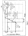
- FIG. 1 illustrates the performance-degrading phenomena of DVR on the bulk electric grid, by showing a Fault-Induced Delayed Voltage Recovery ("FIDVR") following a 230-kV transmission fault in Southern California.
- the x axis is time and the y axis is voltage.
- Section 100 of FIG. 1 depicts the steady state voltage.
- a fault occurs and clears on the grid.
- a fault is a short circuit on the utility line caused by, for example, a tree falling onto the line or a lightning strike, or any other event that would cause a short circuit in the utility line.
- the utility line voltage may drop by half or more.
- the duration of faults on utility transmission and distribution equipment is typically very short 4-10 cycles, or fraction of a second, before the faulted equipment is isolated through the opening of breakers. Normally, voltage at the grid level should immediately return to pre-fault normal levels as soon as the faulted equipment is opened/isolated and fault current ceases to flow.
- a motor for example, an air conditioner
- Some air conditioners disconnect from the grid based on voltage drops, while others only will disconnect when a thermal sensor detects an elevated operating temperature. Therefore, this second set of air conditioners will not disconnect at the voltage drop caused by a fault. Instead, because of the drop in voltage, the air conditioner may stall and draw 6-8 times more current than when in normal operation. The large current draw causes the air conditioner to produce excess heat. These air conditioners may not disconnect until the thermal sensor detects a requisite level of heat, which may be 20-30 seconds after the fault has occurred. The stalled air conditioners also may cause other thermal sensor air conditioners to stall.
- time period 104 is the delayed voltage recovery period during which some loads (e.g. motors, air conditioners, etc.) may stall and start to disconnect from the grid via thermal protection switches.
- period 104 can extend for about 20 seconds.
- a power overshoot typically occurs, caused by line and substation voltage-support capacitors remaining on line.
- the capacitors disconnect because of the overshoot in voltage at time 106.
- the loads that had previously disconnected come back online.
- the grid is under voltage for a time period while the capacitors that turned off at time 108 remain off. This under voltage period increases the likelihood of another delayed voltage recovery event. Taken together the recovery time, that is, the time it takes the system to return to steady state conditions at 100 after fault 102 can last up to approximately 30 seconds.
- the voltage deviation on the grid during a delayed voltage recovery event can be extreme.
- the first recorded DVR event was in the Tennessee Valley Authority transmission system on August 22, 1987. Present systems have been unable to detect DVRs as they occur; most DVRs are detected long after the fact by reviewing power grid data.
- IMAI S "Undervoltage load shedding improving security as reasonable measure for extreme contingencies", POWER ENGINEERING SOCIETY GENERAL MEETING, 2005. IEEE SAN FRANCISCO, CA, USA JUNE 12-16, 2005, PISCATAWAY, NJ, USA,IEEE, 12 June 2005, pages 1156-1161 , relates to Undervoltage load shedding.
- US 6,987,331 relates to a voltage recovery device for use with a utility power network.
- the energy storage based countermeasure system disclosed herein detects and corrects for a delayed voltage recovery event by using a distributed system of grid metering devices and power sources.
- the disclosed system detects the delayed voltage recovery event using grid metering devices deployed throughout the electrical grid, for example, at various locations on the grid from distribution circuits through substations. These grid metering devices communicate with a controller that will trigger operation of distributed power sources when a delayed voltage recovery event is detected.
- the triggered power sources can provide countermeasures to the delayed voltage recovery event by both injecting and absorbing power to and from the grid.
- the described countermeasure to a detected DVR operates by rapidly injecting power (real and reactive) into the electric grid to counteract depressed electric system voltages during bulk electric system DVR events after a fault has occurred and has been cleared, but the system voltage remains depressed for an unacceptable period (10 seconds or more). This countermeasure for a DVR event is able to
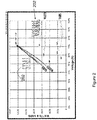
- FIG. 2 depicts typical power characteristics in a power line for both normal conditions 220 and for stall conditions 225.
- the y-axis of the graph is watts and VARS, the x-axis is percent voltage.
- the wattage in the power line is significantly higher than the VARs in the power line (about a 2:1 ratio) and both wattage and VARs are in a relatively stable state with respect to increasing voltage percentage (x-axis).
- the voltage drop can cause inductive loads on the line to stall.
- the stalling can result in an increased voltage drain on the power line, resulting in a delayed recovery to normal operating voltage (a DVR condition).
- a DVR condition As shown in FIG. 2 , in a stalling condition 225, the VARs values exceed the watts values or are at least closer to a 1:1 ratio and both VARs and watts sharply increase with respect to voltage percentage.
- FIG. 2 shows the 70% voltage threshold below which the DVR condition is present. 70% voltage threshold and below is the depth of voltage drop at which motors typically stall, but stay energized by pulling starting current. The stalled motors are the underlying physical cause of the time delay in the voltage recovery. Therefore, when a stall starts, which can result in a DVR, the power line experiences a discrete change in the voltage and the ratio of VARs to watts.
- the DVR system described herein detects and triggers on these shifts in the ratio of VARs to watts and the voltage in the power line.
- the VARs to watts ratio also is related to the power factor of the power line.
- the power factor is the electric phase difference between voltage and current on utility power line.
- real power refers to the portion of power that, averaged over a complete cycle of the AC waveform, results in net transfer of energy in one direction.
- the portion of power due to stored energy, which returns to the source in each cycle is known as reactive power.
- Apparent power refers to the combination of real and reactive power.
- the system also can use power factor as an indicator of a DVR condition.
- a low power factor or a discrete drop in power factor can result in a DVR condition.
- These measurements provide the system the ability to discriminate between a non-DVR electric system conditions that may temporarily depress area voltages, versus an actual DVR condition. Further, other conditions can be used to detect a DVR condition, including harmonic content signature, waveform or shape of the current, or a current spike on the electrical grid.
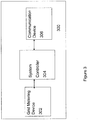
- FIG. 3 depicts a grid module 300, which detects a DVR condition and notifies remote modules which implement countermeasures (to be described below).
- Grid module 300 includes a grid metering device 302 with the capability to measure the VARs, watts, and/or the power factor on a utility/power line.
- An exemplary grid metering device 302 is a LineTracker Conductor Mounted Sensor, manufactured by GridSense, Inc. (West Sacramento, California). Grid metering device 302 constantly monitors power factor, VARS, watts and voltage of the grid. This information is passed to a system controller 304 located in grid module 300.
- Controller 304 determines if the information from metering device 302 indicates a DVR condition on the grid.
- Controller 304 can be a programmable logic controller, a digital based controller, a programmed processor or a computer. If controller 304, based on the information from grid metering device 302, determines that a DVR condition exists, controller 304 causes a communication device 306 to send an alert to distributed system of power modules ( see FIG. 4 ). These power modules then inject a burst of power into the grid to provide a short term maximum power output in close proximity to where the DVR condition was detected. The timeframes involved, i.e. detect DVR condition within fraction of a second to several seconds, then trigger power module response within next 1-2 seconds, then sustain operation for 10-30 seconds, allow for use of a variety of standard communication links and protocols including copper wire, fiber optic, Ethernet, and radio.
- system controller 304 can be remotely located from grid metering device 302.
- system controller 304 can receive information, for example, power factor and terminal voltage values, from a plurality of remotely located grid metering devices 302.
- system controller 304 detects a DVR based on the measured power factor.
- System controller 304 also can measure the local terminal voltage at the system controller and use that value in conjunction with the power factor information received from the grid metering devices to determine if a DVR condition exists.
- FIG. 4 depicts a remotely located power source module 400.
- Power source module 400 includes a power source 402 to provide the power to be injected into (to boost low voltage and supply the current demand of stalled motors) or absorbed from (to reduce high voltage) the utility lines to counteract a DVR condition.
- power source module 400 injects power during period 104, when the voltage is depressed, and absorbs power at period 106, when the voltage is too high.
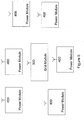
- FIG. 5 which depicts one grid module 300 and six power modules 400, all in wireless communication with each other, power source modules 400 can be part of a distributed system wherein each power module 400 can be located near a load, e.g.
- Grid module 300 can be located anywhere in the grid, for example at a power station or on a remote utility line and can be located remotely or locally to the power source module 400. While FIG. 5 shows only one grid module, a plurality of grid modules could be in communication with a plurality of power modules. Additionally, although the grid module and the power modules are in wireless communication with each other in FIG.
- the present disclosure is not limited to wireless communication and the various modules can communicate with each other through any communication scheme known to those of skill in the art, for example, copper wire, fiber optic, and Ethernet.
- power source module 400 has been described herein as remotely located, power source module 400 could be located in close proximity to grid module 300.
- FIG. 6 depicts a grid module 300 located on a power line 600. Proximate to the grid module 300 are two power modules 400, 400'.
- power module 400 can be a network energy storage device, for example, as manufactured by A123 Systems.
- Power module 400' can be a plug-in hybrid or electric vehicle parked and charging at an owner's residence.
- Power source module 400 includes the following components:
- Bi-directional power source 402 can be any electrochemical, mechanical or thermal device capable of delivering a significant amount of power in under two seconds, i.e., responding from offline to full capacity, and can sustain the power delivery for a time period long enough to counteract a DVR event, for example, approximately thirty seconds. Further, bi-directional power source 402 can, once online, cycle in a random manner (move from charge/discharge up to full capacity in either direction) without causing power device or damage. Bi-directional power source 302 can be, for example, a high power battery, such as batteries manufactured by A123 Systems, Inc. (Watertown, MA).
- the power modules can range from small batteries in electric cars (e.g., a vehicle to grid system) to large arrays of batteries located at a power station or facility. Both the aggregated effect of small distributed battery systems and a large injection from power from a single source can effectively mitigate a DVR condition. Because the disclosed DVR system can use distributed power sources with varying capabilities, the countermeasure to the DVR event can be narrowly tailored to address the specific DVR event at issue. For example, based on the type of DVR condition measured or detected, system controller can activate all power modules in the grid, (e.g., for a large, distributed DVR) or a select few smaller power modules (e.g., for a smaller, localized DVR).
- Bi-directional power source 402 can operate as either a power source or a load. As load, the bi-directional power source 402 can recharge itself by absorbing power from the grid.
- Inverter 404 is the connection between power source 402 and the electric grid. Inverter 404 has the following characteristics: (1) the ability to instantly change output level and direction (e.g., absorbing or injecting) within milliseconds; (2) the ability to apportion the output between reactive (VARS) and real power (Watts) and (3) a modern digital communication and control interface which includes a SMART Grid interoperable control interfaces to enable inverter 404 to talk to a variety of devices on the power system. Thus, inverter 404 apportions the power injection and/or absorption to mirror or counter the existing VAR conditions on the power line in order to balance and stabilize the real, apparent, and reactive power on the line. Inverter 404 also converts the DC power into AC power. The existing conditions on the power line are determined through the use of module metering device 406.
- Communication interface 408 communicates with module controller 410 and metering device 406. Communication interface 408 receives remote communications from communication device 306 of grid module 300.
- Module metering device 406 measures a local terminal voltage at power module 400, i.e., a terminal voltage from the energy storage device.
- Module metering device 406 can be any type of voltage measuring device known to those of skill in the art.
- Module controller 410 is programmed to control the operation of bi-directional power source 402, communication interface 408 and inverter 404.
- Communication interface 408 receives an indication that a DVR condition exists from communication device 306 of grid module 300. If a DVR condition exists, module controller 410 triggers power source 402 to deliver a burst of power to the power grid.
- Module controller 410 determines the power to be added or absorbed from the grid based on the terminal voltage measurements made by module metering device 406. Based on the terminal voltage, module Controller 410 determines (1) magnitude of power, (2) direction and (3) apportionment between Watts/VARS to provide and sustain the appropriate levels of real and reactive power to the power grid.
- Inverter 404 executes the instructions from module controller 410 within a millisecond and delivers and sustains the appropriate levels of real and reactive power to the power grid. Module controller 410 will continue to instruct inverter 404 to output or absorb power until the measured terminal voltage values from module metering device 406 return to their steady state values. In some instances, module controller 410's determination could be overridden by an external operator dispatch, for example, a dispatch to remove the load from the line.
- the disclosed DVR system operates as follows, grid metering devices 302 monitor conditions on the electrical grid. Based on these conditions system controller 304 will determine if there is a DVR event by detecting a relative shift in power factor on the electric grid. In some embodiments, the local terminal voltage can be used in conjunction with the power factor measurements to detect a DVR event or condition. If one or either of the power factor or terminal voltage drops below a threshold value, the system can determine that a DVR condition exists. If system controller 304 detects a DVR, grid module 300 communicates the existence of the DVR event to a plurality of remotely distributed power modules 400.
- these power sources inject or absorb power into or from the electric grid until the DVR event has been counteracted, or power module capacity and/or ratings have been exceeded and output must be reduced or stopped.
- the voltage of the power line is continually monitored by module metering device 406 and based on this information, power module 400 will either continue to either inject power into the electrical grid or absorb power from the grid.
- the system can include a plurality of grid metering device and remote power modules distributed across a power grid.
- Each grid metering device monitors the condition of the power lines where it is located and reports conditions back to one or more system controllers.
- the system controller detects a fault or DVR condition
- the system controller determines, based on the VAR, wattage, power factor, and voltage values measured by the grid metering device, which remote power sources should be enabled. Based on the DVR condition detected, in some situations, system controller request that all available power sources activate to counteract the DVR. In other situations, system controller instructs specific power modules to activate.
- the DVR system can contain multiple system controllers to determine if a DVR condition exists and each system controller can communicate with a plurality of power modules.
- local control at the activated power module will modulate the power output (inject or absorb) to the power line to compensate for the post-fault voltage deviations (low and high), until the voltage normalizes.
- one DVR event may result in the triggering of one remote power source adjacent to the event or, the system may determine that a plurality of power sources are required to counteract the DVR event. Therefore, the system provides a flexible solution to solving DVR problems on power grids by using a unique distributed metering and correction system.
Landscapes
- Engineering & Computer Science (AREA)
- Power Engineering (AREA)
- Physics & Mathematics (AREA)
- General Physics & Mathematics (AREA)
- Remote Monitoring And Control Of Power-Distribution Networks (AREA)
- Supply And Distribution Of Alternating Current (AREA)
- Secondary Cells (AREA)
Description
- This application relates to a delayed voltage recovery, that is, a battery-based delayed voltage recovery ("DVR") system The DVR system can provide a countermeasure to mitigate and reduce the severity of DVR events on bulk electric power grids.
-
FIG. 1 illustrates the performance-degrading phenomena of DVR on the bulk electric grid, by showing a Fault-Induced Delayed Voltage Recovery ("FIDVR") following a 230-kV transmission fault in Southern California. The x axis is time and the y axis is voltage.Section 100 ofFIG. 1 depicts the steady state voltage. At time 102, a fault occurs and clears on the grid. A fault is a short circuit on the utility line caused by, for example, a tree falling onto the line or a lightning strike, or any other event that would cause a short circuit in the utility line. The high currents associated with faults can cause a substantial reduction in line voltage due to the basic relationship of V=IR, or voltage = current times resistance. During the fault, the utility line voltage may drop by half or more. The duration of faults on utility transmission and distribution equipment is typically very short 4-10 cycles, or fraction of a second, before the faulted equipment is isolated through the opening of breakers. Normally, voltage at the grid level should immediately return to pre-fault normal levels as soon as the faulted equipment is opened/isolated and fault current ceases to flow. - However, if the system is not operating normally, during the brief second that the fault is occurring, a motor, for example, an air conditioner, may sense the large voltage drop and stall. Some air conditioners disconnect from the grid based on voltage drops, while others only will disconnect when a thermal sensor detects an elevated operating temperature. Therefore, this second set of air conditioners will not disconnect at the voltage drop caused by a fault. Instead, because of the drop in voltage, the air conditioner may stall and draw 6-8 times more current than when in normal operation. The large current draw causes the air conditioner to produce excess heat. These air conditioners may not disconnect until the thermal sensor detects a requisite level of heat, which may be 20-30 seconds after the fault has occurred. The stalled air conditioners also may cause other thermal sensor air conditioners to stall. This can build upon itself into a type of blackout called a voltage collapse. Therefore, these thermal condition triggered air conditioners exacerbate the fault and create a DVR condition. Because of the growing number of residential air conditioners with thermal sensors, DVR conditions have become a larger problem.
- Referring back to
FIG. 1 ,time period 104 is the delayed voltage recovery period during which some loads (e.g. motors, air conditioners, etc.) may stall and start to disconnect from the grid via thermal protection switches. Typically,period 104 can extend for about 20 seconds. Then, attime 106, a power overshoot typically occurs, caused by line and substation voltage-support capacitors remaining on line. Attime 108, the capacitors disconnect because of the overshoot in voltage attime 106. At time 110, the loads that had previously disconnected come back online. Attime 112, the grid is under voltage for a time period while the capacitors that turned off attime 108 remain off. This under voltage period increases the likelihood of another delayed voltage recovery event. Taken together the recovery time, that is, the time it takes the system to return to steady state conditions at 100 after fault 102 can last up to approximately 30 seconds. As shown inFIG. 1 , the voltage deviation on the grid during a delayed voltage recovery event can be extreme. - The first recorded DVR event was in the Tennessee Valley Authority transmission system on August 22, 1987. Present systems have been unable to detect DVRs as they occur; most DVRs are detected long after the fact by reviewing power grid data.
- Known prior-deployed solutions have included combustion turbine driven electric generators and Static VAR Compensators, or SVC's. However, generators burn fossil fuel, thereby wasting resources and adding green house gasses, and some generators do not have response times adequate (fast enough) to prevent a voltage collapse. SVC's have declining volt-amperes reactive ("VAR") output versus terminal voltage. Thus, when VAR support is needed most, these solutions have reduced output capacity and effectiveness. Currently, there are limited power industry options and solutions to this relatively new/emerging risk to the U.S. electric power system.
- IMAI S: "Undervoltage load shedding improving security as reasonable measure for extreme contingencies", POWER ENGINEERING SOCIETY GENERAL MEETING, 2005. IEEE SAN FRANCISCO, CA, USA JUNE 12-16, 2005, PISCATAWAY, NJ, USA,IEEE, 12 June 2005, pages 1156-1161, relates to Undervoltage load shedding.
US 6,987,331 relates to a voltage recovery device for use with a utility power network. - Some embodiments of the invention provide one or more of the following advantages over existing systems:
- a. ability to impart significant power rapidly and bi-directionally (inject and absorb power) through use of a power source that has a high power capacity, enabling a single device to effectively support a wide area of the electric grid;
- b. ability to discriminate for a specific grid-condition indicative of a delayed voltage recovery event; and
- c. use of a power-electronic interface (inverter) between the power source and the grid to manage the dynamic, rapidly changing bi-directional flow of power that would be delivered during operation of the system to mitigate the delayed voltage recovery.
- According to the invention, systems and methods as defined in the independent claims are provided. Further embodiments are provided as defined in the dependent claims.
- For a more complete understanding of various embodiments of the present disclosure, reference is now made to the following descriptions taken in connection with the accompanying drawings in which:
-
FIG. 1 illustrates a typical FIDVR following a 230-kV transmission fault; -
FIG. 2 depicts typical power characteristics in a power line for both normal conditions and for stall conditions; -
FIG. 3 is a block diagram of a grid module, according to one or more embodiments of the present disclosure; -
FIG. 4 is a block diagram of a power module, according to one or more embodiments of the present disclosure; -
FIG. 5 is a block diagram of a grid module and a plurality of power modules, according to one or more embodiments of the present disclosure; and -
FIG. 6 is an illustration of grid module and two power modules on a utility line, according to one or more embodiments of the present disclosure. - The energy storage based countermeasure system disclosed herein detects and corrects for a delayed voltage recovery event by using a distributed system of grid metering devices and power sources. The disclosed system detects the delayed voltage recovery event using grid metering devices deployed throughout the electrical grid, for example, at various locations on the grid from distribution circuits through substations. These grid metering devices communicate with a controller that will trigger operation of distributed power sources when a delayed voltage recovery event is detected. The triggered power sources can provide countermeasures to the delayed voltage recovery event by both injecting and absorbing power to and from the grid.
- The described countermeasure to a detected DVR operates by rapidly injecting power (real and reactive) into the electric grid to counteract depressed electric system voltages during bulk electric system DVR events after a fault has occurred and has been cleared, but the system voltage remains depressed for an unacceptable period (10 seconds or more). This countermeasure for a DVR event is able to
- 1) detect and discriminate for a DVR condition;
- 2) initiate injection of power into the electric grid via a distributed system of power modules; and
- 3) maintain the injection of power into the electric grid and absorption of power from the grid, even under depressed area voltage conditions, for a predetermined period of time, e.g., 30 seconds.
-
FIG. 2 depicts typical power characteristics in a power line for both normal conditions 220 and for stall conditions 225. The y-axis of the graph is watts and VARS, the x-axis is percent voltage. As shown inFIG. 2 , in normal operating conditions 220, the wattage in the power line is significantly higher than the VARs in the power line (about a 2:1 ratio) and both wattage and VARs are in a relatively stable state with respect to increasing voltage percentage (x-axis). As discussed above, when a fault occurs on a power line or grid with an accompanying voltage drop in the line, the voltage drop can cause inductive loads on the line to stall. The stalling can result in an increased voltage drain on the power line, resulting in a delayed recovery to normal operating voltage (a DVR condition). As shown inFIG. 2 , in a stalling condition 225, the VARs values exceed the watts values or are at least closer to a 1:1 ratio and both VARs and watts sharply increase with respect to voltage percentage. Further,FIG. 2 shows the 70% voltage threshold below which the DVR condition is present. 70% voltage threshold and below is the depth of voltage drop at which motors typically stall, but stay energized by pulling starting current. The stalled motors are the underlying physical cause of the time delay in the voltage recovery. Therefore, when a stall starts, which can result in a DVR, the power line experiences a discrete change in the voltage and the ratio of VARs to watts. - The DVR system described herein detects and triggers on these shifts in the ratio of VARs to watts and the voltage in the power line. The VARs to watts ratio also is related to the power factor of the power line. The power factor is the electric phase difference between voltage and current on utility power line. As used herein, real power refers to the portion of power that, averaged over a complete cycle of the AC waveform, results in net transfer of energy in one direction. As used herein, the portion of power due to stored energy, which returns to the source in each cycle, is known as reactive power. Apparent power refers to the combination of real and reactive power. Thus, the system also can use power factor as an indicator of a DVR condition. Specifically, a low power factor or a discrete drop in power factor can result in a DVR condition. These measurements provide the system the ability to discriminate between a non-DVR electric system conditions that may temporarily depress area voltages, versus an actual DVR condition. Further, other conditions can be used to detect a DVR condition, including harmonic content signature, waveform or shape of the current, or a current spike on the electrical grid.
- Block diagrams of the described system are provided as
FIGs. 3 and4 .FIG. 3 depicts agrid module 300, which detects a DVR condition and notifies remote modules which implement countermeasures (to be described below).Grid module 300 includes agrid metering device 302 with the capability to measure the VARs, watts, and/or the power factor on a utility/power line. An exemplarygrid metering device 302 is a LineTracker Conductor Mounted Sensor, manufactured by GridSense, Inc. (West Sacramento, California).Grid metering device 302 constantly monitors power factor, VARS, watts and voltage of the grid. This information is passed to asystem controller 304 located ingrid module 300.Controller 304 determines if the information frommetering device 302 indicates a DVR condition on the grid.Controller 304 can be a programmable logic controller, a digital based controller, a programmed processor or a computer. Ifcontroller 304, based on the information fromgrid metering device 302, determines that a DVR condition exists,controller 304 causes acommunication device 306 to send an alert to distributed system of power modules (seeFIG. 4 ). These power modules then inject a burst of power into the grid to provide a short term maximum power output in close proximity to where the DVR condition was detected. The timeframes involved, i.e. detect DVR condition within fraction of a second to several seconds, then trigger power module response within next 1-2 seconds, then sustain operation for 10-30 seconds, allow for use of a variety of standard communication links and protocols including copper wire, fiber optic, Ethernet, and radio. - While
FIG. 3 depictssystem controller 304 as co-located withgrid metering device 302, in some embodiments,system controller 304 can be remotely located fromgrid metering device 302. In this embodiment,system controller 304 can receive information, for example, power factor and terminal voltage values, from a plurality of remotely locatedgrid metering devices 302. In one embodiment,system controller 304 detects a DVR based on the measured power factor.System controller 304 also can measure the local terminal voltage at the system controller and use that value in conjunction with the power factor information received from the grid metering devices to determine if a DVR condition exists. -
FIG. 4 depicts a remotely locatedpower source module 400.Power source module 400 includes apower source 402 to provide the power to be injected into (to boost low voltage and supply the current demand of stalled motors) or absorbed from (to reduce high voltage) the utility lines to counteract a DVR condition. Referring back toFIG. 1 ,power source module 400 injects power duringperiod 104, when the voltage is depressed, and absorbs power atperiod 106, when the voltage is too high. As shown inFIG. 5 , which depicts onegrid module 300 and sixpower modules 400, all in wireless communication with each other,power source modules 400 can be part of a distributed system wherein eachpower module 400 can be located near a load, e.g. industrial equipment, motors, etc., or at a centralized location under utility control, for example, a transformer installation or a substation. Notably, the localized injection of power into the power line, close to the motor loads which might be causing the DVR condition, more efficiently and effectively corrects the DVR problem.Grid module 300 can be located anywhere in the grid, for example at a power station or on a remote utility line and can be located remotely or locally to thepower source module 400. WhileFIG. 5 shows only one grid module, a plurality of grid modules could be in communication with a plurality of power modules. Additionally, although the grid module and the power modules are in wireless communication with each other inFIG. 5 , the present disclosure is not limited to wireless communication and the various modules can communicate with each other through any communication scheme known to those of skill in the art, for example, copper wire, fiber optic, and Ethernet. Whilepower source module 400 has been described herein as remotely located,power source module 400 could be located in close proximity togrid module 300. For example,FIG. 6 depicts agrid module 300 located on apower line 600. Proximate to thegrid module 300 are twopower modules 400, 400'. As shown inFIG. 6 ,power module 400 can be a network energy storage device, for example, as manufactured by A123 Systems. Power module 400' can be a plug-in hybrid or electric vehicle parked and charging at an owner's residence. -
Power source module 400 includes the following components: - 1) a
bi-directional power source 402, for example, a battery, that can deliver and sustain real and reactive power, even under severely depressed voltage conditions; - 2) an
inverter 404, for example, a power electronics interface betweenpower source 402 and electric grid; - 3) a
module metering device 406 for measuring a terminal voltage atpower module 400; - 4) a
communication interface 408 to receive communication fromgrid metering module 300; and - 5) a
module controller 410 to manage these discrete subsystems. -
Bi-directional power source 402 can be any electrochemical, mechanical or thermal device capable of delivering a significant amount of power in under two seconds, i.e., responding from offline to full capacity, and can sustain the power delivery for a time period long enough to counteract a DVR event, for example, approximately thirty seconds. Further,bi-directional power source 402 can, once online, cycle in a random manner (move from charge/discharge up to full capacity in either direction) without causing power device or damage.Bi-directional power source 302 can be, for example, a high power battery, such as batteries manufactured by A123 Systems, Inc. (Watertown, MA). The power modules can range from small batteries in electric cars (e.g., a vehicle to grid system) to large arrays of batteries located at a power station or facility. Both the aggregated effect of small distributed battery systems and a large injection from power from a single source can effectively mitigate a DVR condition. Because the disclosed DVR system can use distributed power sources with varying capabilities, the countermeasure to the DVR event can be narrowly tailored to address the specific DVR event at issue. For example, based on the type of DVR condition measured or detected, system controller can activate all power modules in the grid, (e.g., for a large, distributed DVR) or a select few smaller power modules (e.g., for a smaller, localized DVR). Other examples of a bi-directional power source that could be used include an ultra-capacitor (energy capacitor) or a flywheel (or other mechanical energy storage) based devices.Bi-directional power source 402 can operate as either a power source or a load. As load, thebi-directional power source 402 can recharge itself by absorbing power from the grid. -
Inverter 404 is the connection betweenpower source 402 and the electric grid.Inverter 404 has the following characteristics: (1) the ability to instantly change output level and direction (e.g., absorbing or injecting) within milliseconds; (2) the ability to apportion the output between reactive (VARS) and real power (Watts) and (3) a modern digital communication and control interface which includes a SMART Grid interoperable control interfaces to enableinverter 404 to talk to a variety of devices on the power system. Thus,inverter 404 apportions the power injection and/or absorption to mirror or counter the existing VAR conditions on the power line in order to balance and stabilize the real, apparent, and reactive power on the line.Inverter 404 also converts the DC power into AC power. The existing conditions on the power line are determined through the use ofmodule metering device 406. -
Communication interface 408 communicates withmodule controller 410 andmetering device 406.Communication interface 408 receives remote communications fromcommunication device 306 ofgrid module 300. -
Module metering device 406 measures a local terminal voltage atpower module 400, i.e., a terminal voltage from the energy storage device.Module metering device 406 can be any type of voltage measuring device known to those of skill in the art. -
Module controller 410 is programmed to control the operation ofbi-directional power source 402,communication interface 408 andinverter 404.Communication interface 408 receives an indication that a DVR condition exists fromcommunication device 306 ofgrid module 300. If a DVR condition exists,module controller 410 triggerspower source 402 to deliver a burst of power to the power grid.Module controller 410 determines the power to be added or absorbed from the grid based on the terminal voltage measurements made bymodule metering device 406. Based on the terminal voltage,module Controller 410 determines (1) magnitude of power, (2) direction and (3) apportionment between Watts/VARS to provide and sustain the appropriate levels of real and reactive power to the power grid.Inverter 404 executes the instructions frommodule controller 410 within a millisecond and delivers and sustains the appropriate levels of real and reactive power to the power grid.Module controller 410 will continue to instructinverter 404 to output or absorb power until the measured terminal voltage values frommodule metering device 406 return to their steady state values. In some instances,module controller 410's determination could be overridden by an external operator dispatch, for example, a dispatch to remove the load from the line. - The disclosed DVR system operates as follows,
grid metering devices 302 monitor conditions on the electrical grid. Based on theseconditions system controller 304 will determine if there is a DVR event by detecting a relative shift in power factor on the electric grid. In some embodiments, the local terminal voltage can be used in conjunction with the power factor measurements to detect a DVR event or condition. If one or either of the power factor or terminal voltage drops below a threshold value, the system can determine that a DVR condition exists. Ifsystem controller 304 detects a DVR,grid module 300 communicates the existence of the DVR event to a plurality of remotely distributedpower modules 400. Then, these power sources, based on local measured terminal voltage at each power module, inject or absorb power into or from the electric grid until the DVR event has been counteracted, or power module capacity and/or ratings have been exceeded and output must be reduced or stopped. During the DVR event, the voltage of the power line is continually monitored bymodule metering device 406 and based on this information,power module 400 will either continue to either inject power into the electrical grid or absorb power from the grid. - As discussed above, the system can include a plurality of grid metering device and remote power modules distributed across a power grid. Each grid metering device monitors the condition of the power lines where it is located and reports conditions back to one or more system controllers. When the system controller detects a fault or DVR condition, the system controller determines, based on the VAR, wattage, power factor, and voltage values measured by the grid metering device, which remote power sources should be enabled. Based on the DVR condition detected, in some situations, system controller request that all available power sources activate to counteract the DVR. In other situations, system controller instructs specific power modules to activate. Further, the DVR system can contain multiple system controllers to determine if a DVR condition exists and each system controller can communicate with a plurality of power modules. Once enabled, local control at the activated power module will modulate the power output (inject or absorb) to the power line to compensate for the post-fault voltage deviations (low and high), until the voltage normalizes. For example, one DVR event may result in the triggering of one remote power source adjacent to the event or, the system may determine that a plurality of power sources are required to counteract the DVR event. Therefore, the system provides a flexible solution to solving DVR problems on power grids by using a unique distributed metering and correction system.
- While there have been shown and described examples of the present invention, it will be readily apparent to those skilled in the art that various changes and modifications may be made therein without departing from the scope of the invention, as defined by the appended claims.
Claims (12)
- A system (300) comprising:a metering device (302) for monitoring electrical power grid conditions, the electrical power grid conditions comprising a change in the voltage and ratio of VARs to Watts;a controller (304) for determining, based on the change in the voltage and ratio of VARs to Watts, if the metering device (302) is detecting a condition on an electrical grid that is indicative of a delayed voltage recovery event; anda communication device (306) for communicating with one or more remotely located bi-directional power source modules (400) connected to the electrical power grid,wherein the controller (304) is programmed to send a notification via the communication device (306) to the one or more remotely located bi-directional power source modules (400) if the controller (304) detects a condition indicative of delayed voltage recovery event.
- The system of claim 1 wherein the metering device (302) comprises a grid metering device.
- The system of claim 1, wherein the electrical power grid conditions comprise power factor.
- A system (400) comprising:a bi-directional power source (402);an inverter (404) for connecting the bi-directional power source (402) to an electrical grid; and characterized by further comprising:a communication interface (408) for receiving communications from a remote device (300), wherein the remote device (300) comprises a system according to claim 1;a metering device (406) for measuring one or more characteristics of the electrical grid; anda controller (410) in electrical communication with the inverter (404), the communication interface (408) and the metering device (406),wherein the controller (410) is programmed to respond to a notification of a delayed voltage recovery event sent by the remote device (300) and received from the communication interface (408) by causing the inverter (404) to counteract the delayed voltage recovery event; andwherein the inverter (404) counteracts the delayed voltage recovery event by injecting power from the bi-directional power source (402) into the electric grid or extracting power from the electrical grid based on the one or more characteristics measured by the metering device (406).
- The system of claim 4, wherein:the bi-directional power source (402) comprises a battery; orthe bi-directional power source (402) comprises an energy capacitor or a mechanical energy storage device; orthe metering device (406) comprises a terminal voltage metering device.
- A system comprising:a grid metering device (302) for monitoring electrical power grid conditions, the electrical power grid conditions comprising a change in the voltage and ratio of VARs to Watts; a system controller (304) for determining, based on the change in the voltage and ratio of VARs to Watts, if the grid metering device (302) is detecting a condition on the electrical grid that is indicative of a delayed voltage recovery event; one or more remotely located bi-directional power source modules (400) each comprising:a bi-directional power source (402);an inverter (404) for connecting the bi-directional power source (402) to the electrical grid;a communication interface (408) for receiving communications;a module metering device (406) for measuring one or more characteristics of the electrical grid; anda module controller (410) in electrical communication with the inverter (404), the communication interface (408) and the module metering device (406); anda communication device (306) for communicating with the communication interfaces (408) of the one or more remotely located bi-directional power source modules (400) connected to the electrical power grid;wherein the system controller (304) is programmed to send a notification via the communication device (306) to the one or more remotely located bi-directional power source modules (400) if the system controller (304) detects a condition indicative of the delayed voltage recovery event;wherein the module controller (410) is programmed to respond to the notification of the delayed voltage recovery event sent by the system controller (304) and received from the communication device (306) by causing the inverter (404) to counteract the delayed voltage recovery event; andwherein the inverter (404) counteracts the delayed voltage recovery by injecting power from the bi-directional power source (402) into the electric grid or extracting power from the electrical grid based on the one or more characteristics measured by the module metering device (406).
- The system of claim 6, wherein:the bi-directional power source (402) comprises a battery; orthe bi-directional power source (402) comprises an energy capacitor or a mechanical energy storage device; orthe electrical power grid conditions comprise power factor; orthe one or more conditions measured by the module metering device (406) comprise terminal voltage.
- A method comprising:monitoring one or more conditions on an electrical power grid, the electrical power grid conditions comprising a change in the voltage and ratio of VARs to Watts;determining, based on the change in the voltage and ratio of VARs to Watts, if the one or more conditions on the electrical grid is indicative of a delayed voltage recovery event; andtransmitting a notification to one or more remotely located bi-directional power source modules (400) if a condition indicative of delayed voltage recovery event is determined.
- A method comprising:receiving a notification of a delayed voltage recovery event from a remote device (300) comprising the system of claim 1;measuring one or more characteristics of the electrical grid; andcounteracting the delayed voltage recovery event by injecting power from a bi-directional power source (402) into the electric grid or extracting power from the electrical grid based on the one or more of the measured characteristics.
- The method of claim 9, wherein:the bi-directional power source (402) comprises a battery; orthe bi-directional power source (402) comprises an energy capacitor or a mechanical energy storage device; orthe characteristics of the electrical grid comprise terminal voltage.
- A method comprising:monitoring one or more conditions on an electrical grid, the conditions comprising a change in the voltage and ratio of VARs to Watts;determining, based on the change in the voltage and ratio of VARs to Watts, if the one or more conditions on the electrical grid is indicative of a delayed voltage recovery event;transmitting a notification to one or more remotely located bi-directional power source modules (400) if a condition indicative of the delayed voltage recovery event is determined;receiving at the one or more remotely located bi-directional power source modules (400) the notification of a delayed voltage recovery event;measuring at the remote location one or more characteristics of the electrical grid; andcounteracting the delayed voltage recovery event by injecting power from the bi-directional power source (402) into the electric grid or extracting power from the electrical grid based on the one or more characteristics measured at the remote location.
- The method of claim 11, wherein:the bi-directional power source (402) comprises a battery; orthe bi-directional power source (402) comprises an energy capacitor or a mechanical energy storage device; orthe characteristics measured at the remote location comprise terminal voltage.
Applications Claiming Priority (2)
| Application Number | Priority Date | Filing Date | Title |
|---|---|---|---|
| US24637209P | 2009-09-28 | 2009-09-28 | |
| PCT/US2010/050527 WO2011038392A1 (en) | 2009-09-28 | 2010-09-28 | Energy storage based countermeasure for a delayed voltage recovery |
Publications (3)
| Publication Number | Publication Date |
|---|---|
| EP2484182A1 EP2484182A1 (en) | 2012-08-08 |
| EP2484182A4 EP2484182A4 (en) | 2014-01-22 |
| EP2484182B1 true EP2484182B1 (en) | 2017-06-21 |
Family
ID=43779479
Family Applications (1)
| Application Number | Title | Priority Date | Filing Date |
|---|---|---|---|
| EP10819644.5A Active EP2484182B1 (en) | 2009-09-28 | 2010-09-28 | Energy storage based countermeasure for a delayed voltage recovery |
Country Status (4)
| Country | Link |
|---|---|
| US (1) | US8935111B2 (en) |
| EP (1) | EP2484182B1 (en) |
| CN (1) | CN202997562U (en) |
| WO (1) | WO2011038392A1 (en) |
Families Citing this family (21)
| Publication number | Priority date | Publication date | Assignee | Title |
|---|---|---|---|---|
| US8330293B2 (en) * | 2010-04-09 | 2012-12-11 | GM Global Technology Operations LLC | Power factor correction system |
| US8405247B2 (en) * | 2010-12-16 | 2013-03-26 | General Electric Company | Method and apparatus for control of fault-induced delayed voltage recovery (FIDVR) with photovoltaic and other inverter-based devices |
| US20120169300A1 (en) * | 2011-01-04 | 2012-07-05 | General Electric Company | Integrated electric meter with var capability |
| EP2555141A1 (en) * | 2011-08-03 | 2013-02-06 | Alcatel Lucent | A method, a system, a server, a control element, a computer program and a computer program product for operating a power grid having decentralized control elements |
| US9134746B2 (en) | 2011-09-16 | 2015-09-15 | Varentec, Inc. | Systems and methods for harmonic resonance control |
| US9014867B2 (en) | 2011-09-16 | 2015-04-21 | Varentec, Inc. | Systems and methods for edge of network voltage control of a power grid |
| US10541533B2 (en) | 2011-09-16 | 2020-01-21 | Varentec, Inc. | Systems and methods for edge of network voltage control of a power grid |
| US9104184B2 (en) | 2011-09-16 | 2015-08-11 | Varentec, Inc. | Systems and methods for switch-controlled VAR sources coupled to a power grid |
| US9948100B2 (en) | 2011-09-16 | 2018-04-17 | Varentec, Inc. | Zero droop voltage control for smart inverters |
| KR20140098839A (en) * | 2011-12-06 | 2014-08-08 | 바렌틱, 인코포레이티드. | Systems and Methods for switch-controlled VAR sources coupled to a power grid |
| US9065321B2 (en) | 2011-12-22 | 2015-06-23 | Varentec, Inc. | Isolated dynamic current converters |
| US8352900B1 (en) * | 2012-01-24 | 2013-01-08 | International Business Machines Corporation | Analytic experimental estimator for impact of voltage-overshoot of voltage waveform on dielectric failure/breakdown |
| US9304522B2 (en) | 2012-04-19 | 2016-04-05 | Varentec, Inc. | Systems and methods for dynamic AC line voltage regulation with energy saving tracking |
| US9368968B2 (en) * | 2012-12-28 | 2016-06-14 | Younicos, Inc. | Responding to local grid events and distributed grid events |
| US9954366B2 (en) | 2013-07-11 | 2018-04-24 | General Electric Company | Grid power factor control system |
| US9599651B2 (en) * | 2015-02-19 | 2017-03-21 | Nec Energy Solutions, Inc. | Systems and methods of detecting ground faults in energy storage and/or generation systems that employ DC/AC power conversion systems |
| US9798342B2 (en) * | 2015-02-23 | 2017-10-24 | Schweitzer Engineering Laboratories, Inc. | Detection and correction of fault induced delayed voltage recovery |
| WO2017039645A1 (en) * | 2015-09-02 | 2017-03-09 | United Technologies Corporation | Multifunctional power correction device |
| US10411469B2 (en) | 2017-12-07 | 2019-09-10 | Inventus Holdings, Llc | Reactive power control integrated with renewable energy power invertor |
| US11462909B2 (en) | 2020-06-09 | 2022-10-04 | Sensus Spectrum, Llc | Methods, systems and computer program products for reducing instability in the power grid |
| CN112421967B (en) * | 2020-10-30 | 2022-01-18 | 怀化学院 | Dynamic voltage restorer system for integrated circuit precision machining equipment |
Family Cites Families (6)
| Publication number | Priority date | Publication date | Assignee | Title |
|---|---|---|---|---|
| US2196029A (en) * | 1937-08-11 | 1940-04-02 | Gen Electric | Electric circuit |
| US3196336A (en) * | 1961-06-09 | 1965-07-20 | Borg Warner | Bidirectional power supply system |
| EP0564149B1 (en) * | 1992-04-03 | 1997-09-24 | JEOL Ltd. | Storage capacitor power supply |
| WO2000048286A1 (en) * | 1999-01-29 | 2000-08-17 | American Superconductor Corporation | Electric utility system with superconducting magnetic energy storage |
| US6392856B1 (en) * | 2000-04-24 | 2002-05-21 | American Superconductor Corporation | Method and system for providing voltage support to a load connected to a utility power network |
| US20080077336A1 (en) * | 2006-09-25 | 2008-03-27 | Roosevelt Fernandes | Power line universal monitor |
-
2010
- 2010-09-28 EP EP10819644.5A patent/EP2484182B1/en active Active
- 2010-09-28 WO PCT/US2010/050527 patent/WO2011038392A1/en not_active Ceased
- 2010-09-28 US US12/891,945 patent/US8935111B2/en active Active
- 2010-09-28 CN CN2010900013365U patent/CN202997562U/en not_active Expired - Lifetime
Non-Patent Citations (1)
| Title |
|---|
| None * |
Also Published As
| Publication number | Publication date |
|---|---|
| US20110074215A1 (en) | 2011-03-31 |
| EP2484182A4 (en) | 2014-01-22 |
| WO2011038392A1 (en) | 2011-03-31 |
| EP2484182A1 (en) | 2012-08-08 |
| CN202997562U (en) | 2013-06-12 |
| US8935111B2 (en) | 2015-01-13 |
Similar Documents
| Publication | Publication Date | Title |
|---|---|---|
| US8935111B2 (en) | Energy storage based countermeasure for a delayed voltage recovery | |
| US11231733B2 (en) | System and method of power control for an energy storage charging station | |
| EP2736142B1 (en) | Fault diagnosis method, grid-interconnected device, and control device | |
| EP3553911B1 (en) | Microgrid system, and method for managing malfunction | |
| HUE025941T2 (en) | Photovoltaic module | |
| CN102324753A (en) | Energy storage control method of battery energy storage system | |
| CN106602689B (en) | A system for preventing DC power bus from losing voltage and its operation method | |
| WO2015008467A1 (en) | System controlling base station device connected to power grid, base station device, base station device control device, and charging control method therefor | |
| KR101314123B1 (en) | Switchgear for controling peak using distributed generation of grid connected | |
| US12283814B2 (en) | Circuit management system | |
| WO2016156309A1 (en) | Energy supply system with power meter and selective load shedding | |
| CN105990868A (en) | Cell management system used in electricity changing energy storage system | |
| CN102830365A (en) | Megawatt-level wind generating set paddle changing system battery automatic testing method and system | |
| CN115967141A (en) | Remote operation and maintenance system and method for direct-current power supply equipment based on cloud platform | |
| US8890491B2 (en) | High voltage DC power source and a power apparatus for a high voltage electrical power system | |
| CN213637184U (en) | Industrial standby power supply system | |
| US9979228B2 (en) | Energy management apparatus and method of controlling the same | |
| CN106253354A (en) | Grid-connected electric power system and the method for not surfing the Net | |
| CN205986190U (en) | Power supply system that does not surf net is incorporated into power networks | |
| Anwar et al. | Fault-Aware-Soft-Restart method for shipboard MVAC power system using inverter coupled energy storage system | |
| KR102303326B1 (en) | An energy storage system | |
| CN121180486A (en) | All-electric propulsion satellite energy fully autonomous management method and system | |
| CN115817250A (en) | Tramcar ground charging control method, device, equipment and storage medium | |
| CN119324554A (en) | Multi-protection self-adaptive analog quantity starting power supply fast switching system | |
| CN121756960A (en) | Charging power control method of charging pile, controller and optical storage charging system |
Legal Events
| Date | Code | Title | Description |
|---|---|---|---|
| PUAI | Public reference made under article 153(3) epc to a published international application that has entered the european phase |
Free format text: ORIGINAL CODE: 0009012 |
|
| 17P | Request for examination filed |
Effective date: 20120424 |
|
| AK | Designated contracting states |
Kind code of ref document: A1 Designated state(s): AL AT BE BG CH CY CZ DE DK EE ES FI FR GB GR HR HU IE IS IT LI LT LU LV MC MK MT NL NO PL PT RO SE SI SK SM TR |
|
| DAX | Request for extension of the european patent (deleted) | ||
| RIC1 | Information provided on ipc code assigned before grant |
Ipc: H02J 3/32 20060101ALI20131212BHEP Ipc: H05B 39/00 20060101AFI20131212BHEP Ipc: H02J 3/18 20060101ALN20131212BHEP Ipc: H02J 13/00 20060101ALI20131212BHEP |
|
| A4 | Supplementary search report drawn up and despatched |
Effective date: 20140103 |
|
| RIC1 | Information provided on ipc code assigned before grant |
Ipc: H05B 39/00 20060101AFI20131219BHEP Ipc: H02J 3/18 20060101ALN20131219BHEP Ipc: H02J 13/00 20060101ALI20131219BHEP Ipc: H02J 3/32 20060101ALI20131219BHEP |
|
| GRAP | Despatch of communication of intention to grant a patent |
Free format text: ORIGINAL CODE: EPIDOSNIGR1 |
|
| RIC1 | Information provided on ipc code assigned before grant |
Ipc: H02J 3/00 20060101ALN20160727BHEP Ipc: H02J 3/12 20060101AFI20160727BHEP Ipc: H02J 3/18 20060101ALN20160727BHEP Ipc: H02J 3/32 20060101ALI20160727BHEP Ipc: H02J 13/00 20060101ALI20160727BHEP Ipc: G01D 4/00 20060101ALI20160727BHEP |
|
| INTG | Intention to grant announced |
Effective date: 20160818 |
|
| GRAJ | Information related to disapproval of communication of intention to grant by the applicant or resumption of examination proceedings by the epo deleted |
Free format text: ORIGINAL CODE: EPIDOSDIGR1 |
|
| GRAP | Despatch of communication of intention to grant a patent |
Free format text: ORIGINAL CODE: EPIDOSNIGR1 |
|
| INTC | Intention to grant announced (deleted) | ||
| RIC1 | Information provided on ipc code assigned before grant |
Ipc: H02J 3/00 20060101ALN20170112BHEP Ipc: H02J 3/12 20060101AFI20170112BHEP Ipc: H02J 3/18 20060101ALN20170112BHEP Ipc: H02J 3/32 20060101ALI20170112BHEP Ipc: H02J 13/00 20060101ALI20170112BHEP Ipc: G01D 4/00 20060101ALI20170112BHEP |
|
| INTG | Intention to grant announced |
Effective date: 20170201 |
|
| RAP1 | Party data changed (applicant data changed or rights of an application transferred) |
Owner name: NEC ENERGY SOLUTIONS, INC. |
|
| GRAJ | Information related to disapproval of communication of intention to grant by the applicant or resumption of examination proceedings by the epo deleted |
Free format text: ORIGINAL CODE: EPIDOSDIGR1 |
|
| REG | Reference to a national code |
Ref country code: DE Ref legal event code: R079 Ref document number: 602010043178 Country of ref document: DE Free format text: PREVIOUS MAIN CLASS: H05B0039000000 Ipc: H02J0003120000 |
|
| GRAR | Information related to intention to grant a patent recorded |
Free format text: ORIGINAL CODE: EPIDOSNIGR71 |
|
| GRAS | Grant fee paid |
Free format text: ORIGINAL CODE: EPIDOSNIGR3 |
|
| GRAA | (expected) grant |
Free format text: ORIGINAL CODE: 0009210 |
|
| INTC | Intention to grant announced (deleted) | ||
| RIC1 | Information provided on ipc code assigned before grant |
Ipc: H02J 3/18 20060101ALN20170511BHEP Ipc: G01D 4/00 20060101ALI20170511BHEP Ipc: H02J 3/00 20060101ALN20170511BHEP Ipc: H02J 3/32 20060101ALI20170511BHEP Ipc: H02J 3/12 20060101AFI20170511BHEP Ipc: H02J 13/00 20060101ALI20170511BHEP |
|
| AK | Designated contracting states |
Kind code of ref document: B1 Designated state(s): AL AT BE BG CH CY CZ DE DK EE ES FI FR GB GR HR HU IE IS IT LI LT LU LV MC MK MT NL NO PL PT RO SE SI SK SM TR |
|
| INTG | Intention to grant announced |
Effective date: 20170515 |
|
| REG | Reference to a national code |
Ref country code: GB Ref legal event code: FG4D |
|
| REG | Reference to a national code |
Ref country code: CH Ref legal event code: EP |
|
| REG | Reference to a national code |
Ref country code: IE Ref legal event code: FG4D |
|
| REG | Reference to a national code |
Ref country code: AT Ref legal event code: REF Ref document number: 903735 Country of ref document: AT Kind code of ref document: T Effective date: 20170715 |
|
| REG | Reference to a national code |
Ref country code: DE Ref legal event code: R096 Ref document number: 602010043178 Country of ref document: DE |
|
| REG | Reference to a national code |
Ref country code: FR Ref legal event code: PLFP Year of fee payment: 8 |
|
| REG | Reference to a national code |
Ref country code: NL Ref legal event code: MP Effective date: 20170621 |
|
| PG25 | Lapsed in a contracting state [announced via postgrant information from national office to epo] |
Ref country code: LT Free format text: LAPSE BECAUSE OF FAILURE TO SUBMIT A TRANSLATION OF THE DESCRIPTION OR TO PAY THE FEE WITHIN THE PRESCRIBED TIME-LIMIT Effective date: 20170621 Ref country code: HR Free format text: LAPSE BECAUSE OF FAILURE TO SUBMIT A TRANSLATION OF THE DESCRIPTION OR TO PAY THE FEE WITHIN THE PRESCRIBED TIME-LIMIT Effective date: 20170621 Ref country code: NO Free format text: LAPSE BECAUSE OF FAILURE TO SUBMIT A TRANSLATION OF THE DESCRIPTION OR TO PAY THE FEE WITHIN THE PRESCRIBED TIME-LIMIT Effective date: 20170921 Ref country code: GR Free format text: LAPSE BECAUSE OF FAILURE TO SUBMIT A TRANSLATION OF THE DESCRIPTION OR TO PAY THE FEE WITHIN THE PRESCRIBED TIME-LIMIT Effective date: 20170922 Ref country code: FI Free format text: LAPSE BECAUSE OF FAILURE TO SUBMIT A TRANSLATION OF THE DESCRIPTION OR TO PAY THE FEE WITHIN THE PRESCRIBED TIME-LIMIT Effective date: 20170621 |
|
| REG | Reference to a national code |
Ref country code: LT Ref legal event code: MG4D |
|
| REG | Reference to a national code |
Ref country code: AT Ref legal event code: MK05 Ref document number: 903735 Country of ref document: AT Kind code of ref document: T Effective date: 20170621 |
|
| PG25 | Lapsed in a contracting state [announced via postgrant information from national office to epo] |
Ref country code: BG Free format text: LAPSE BECAUSE OF FAILURE TO SUBMIT A TRANSLATION OF THE DESCRIPTION OR TO PAY THE FEE WITHIN THE PRESCRIBED TIME-LIMIT Effective date: 20170921 Ref country code: LV Free format text: LAPSE BECAUSE OF FAILURE TO SUBMIT A TRANSLATION OF THE DESCRIPTION OR TO PAY THE FEE WITHIN THE PRESCRIBED TIME-LIMIT Effective date: 20170621 Ref country code: NL Free format text: LAPSE BECAUSE OF FAILURE TO SUBMIT A TRANSLATION OF THE DESCRIPTION OR TO PAY THE FEE WITHIN THE PRESCRIBED TIME-LIMIT Effective date: 20170621 Ref country code: SE Free format text: LAPSE BECAUSE OF FAILURE TO SUBMIT A TRANSLATION OF THE DESCRIPTION OR TO PAY THE FEE WITHIN THE PRESCRIBED TIME-LIMIT Effective date: 20170621 |
|
| PG25 | Lapsed in a contracting state [announced via postgrant information from national office to epo] |
Ref country code: SK Free format text: LAPSE BECAUSE OF FAILURE TO SUBMIT A TRANSLATION OF THE DESCRIPTION OR TO PAY THE FEE WITHIN THE PRESCRIBED TIME-LIMIT Effective date: 20170621 Ref country code: RO Free format text: LAPSE BECAUSE OF FAILURE TO SUBMIT A TRANSLATION OF THE DESCRIPTION OR TO PAY THE FEE WITHIN THE PRESCRIBED TIME-LIMIT Effective date: 20170621 Ref country code: EE Free format text: LAPSE BECAUSE OF FAILURE TO SUBMIT A TRANSLATION OF THE DESCRIPTION OR TO PAY THE FEE WITHIN THE PRESCRIBED TIME-LIMIT Effective date: 20170621 Ref country code: AT Free format text: LAPSE BECAUSE OF FAILURE TO SUBMIT A TRANSLATION OF THE DESCRIPTION OR TO PAY THE FEE WITHIN THE PRESCRIBED TIME-LIMIT Effective date: 20170621 Ref country code: CZ Free format text: LAPSE BECAUSE OF FAILURE TO SUBMIT A TRANSLATION OF THE DESCRIPTION OR TO PAY THE FEE WITHIN THE PRESCRIBED TIME-LIMIT Effective date: 20170621 |
|
| PG25 | Lapsed in a contracting state [announced via postgrant information from national office to epo] |
Ref country code: ES Free format text: LAPSE BECAUSE OF FAILURE TO SUBMIT A TRANSLATION OF THE DESCRIPTION OR TO PAY THE FEE WITHIN THE PRESCRIBED TIME-LIMIT Effective date: 20170621 Ref country code: IS Free format text: LAPSE BECAUSE OF FAILURE TO SUBMIT A TRANSLATION OF THE DESCRIPTION OR TO PAY THE FEE WITHIN THE PRESCRIBED TIME-LIMIT Effective date: 20171021 Ref country code: SM Free format text: LAPSE BECAUSE OF FAILURE TO SUBMIT A TRANSLATION OF THE DESCRIPTION OR TO PAY THE FEE WITHIN THE PRESCRIBED TIME-LIMIT Effective date: 20170621 Ref country code: IT Free format text: LAPSE BECAUSE OF FAILURE TO SUBMIT A TRANSLATION OF THE DESCRIPTION OR TO PAY THE FEE WITHIN THE PRESCRIBED TIME-LIMIT Effective date: 20170621 Ref country code: PL Free format text: LAPSE BECAUSE OF FAILURE TO SUBMIT A TRANSLATION OF THE DESCRIPTION OR TO PAY THE FEE WITHIN THE PRESCRIBED TIME-LIMIT Effective date: 20170621 |
|
| REG | Reference to a national code |
Ref country code: DE Ref legal event code: R097 Ref document number: 602010043178 Country of ref document: DE |
|
| PLBE | No opposition filed within time limit |
Free format text: ORIGINAL CODE: 0009261 |
|
| STAA | Information on the status of an ep patent application or granted ep patent |
Free format text: STATUS: NO OPPOSITION FILED WITHIN TIME LIMIT |
|
| PG25 | Lapsed in a contracting state [announced via postgrant information from national office to epo] |
Ref country code: DK Free format text: LAPSE BECAUSE OF FAILURE TO SUBMIT A TRANSLATION OF THE DESCRIPTION OR TO PAY THE FEE WITHIN THE PRESCRIBED TIME-LIMIT Effective date: 20170621 |
|
| REG | Reference to a national code |
Ref country code: CH Ref legal event code: PL |
|
| 26N | No opposition filed |
Effective date: 20180322 |
|
| PG25 | Lapsed in a contracting state [announced via postgrant information from national office to epo] |
Ref country code: MC Free format text: LAPSE BECAUSE OF FAILURE TO SUBMIT A TRANSLATION OF THE DESCRIPTION OR TO PAY THE FEE WITHIN THE PRESCRIBED TIME-LIMIT Effective date: 20170621 |
|
| REG | Reference to a national code |
Ref country code: BE Ref legal event code: MM Effective date: 20170930 |
|
| PG25 | Lapsed in a contracting state [announced via postgrant information from national office to epo] |
Ref country code: LU Free format text: LAPSE BECAUSE OF NON-PAYMENT OF DUE FEES Effective date: 20170928 |
|
| PG25 | Lapsed in a contracting state [announced via postgrant information from national office to epo] |
Ref country code: CH Free format text: LAPSE BECAUSE OF NON-PAYMENT OF DUE FEES Effective date: 20170930 Ref country code: LI Free format text: LAPSE BECAUSE OF NON-PAYMENT OF DUE FEES Effective date: 20170930 |
|
| REG | Reference to a national code |
Ref country code: FR Ref legal event code: PLFP Year of fee payment: 9 |
|
| PG25 | Lapsed in a contracting state [announced via postgrant information from national office to epo] |
Ref country code: SI Free format text: LAPSE BECAUSE OF FAILURE TO SUBMIT A TRANSLATION OF THE DESCRIPTION OR TO PAY THE FEE WITHIN THE PRESCRIBED TIME-LIMIT Effective date: 20170621 Ref country code: BE Free format text: LAPSE BECAUSE OF NON-PAYMENT OF DUE FEES Effective date: 20170930 |
|
| PG25 | Lapsed in a contracting state [announced via postgrant information from national office to epo] |
Ref country code: MT Free format text: LAPSE BECAUSE OF NON-PAYMENT OF DUE FEES Effective date: 20170928 |
|
| PG25 | Lapsed in a contracting state [announced via postgrant information from national office to epo] |
Ref country code: HU Free format text: LAPSE BECAUSE OF FAILURE TO SUBMIT A TRANSLATION OF THE DESCRIPTION OR TO PAY THE FEE WITHIN THE PRESCRIBED TIME-LIMIT; INVALID AB INITIO Effective date: 20100928 |
|
| PG25 | Lapsed in a contracting state [announced via postgrant information from national office to epo] |
Ref country code: CY Free format text: LAPSE BECAUSE OF NON-PAYMENT OF DUE FEES Effective date: 20170621 |
|
| PG25 | Lapsed in a contracting state [announced via postgrant information from national office to epo] |
Ref country code: MK Free format text: LAPSE BECAUSE OF FAILURE TO SUBMIT A TRANSLATION OF THE DESCRIPTION OR TO PAY THE FEE WITHIN THE PRESCRIBED TIME-LIMIT Effective date: 20170621 |
|
| PG25 | Lapsed in a contracting state [announced via postgrant information from national office to epo] |
Ref country code: TR Free format text: LAPSE BECAUSE OF FAILURE TO SUBMIT A TRANSLATION OF THE DESCRIPTION OR TO PAY THE FEE WITHIN THE PRESCRIBED TIME-LIMIT Effective date: 20170621 |
|
| PG25 | Lapsed in a contracting state [announced via postgrant information from national office to epo] |
Ref country code: PT Free format text: LAPSE BECAUSE OF FAILURE TO SUBMIT A TRANSLATION OF THE DESCRIPTION OR TO PAY THE FEE WITHIN THE PRESCRIBED TIME-LIMIT Effective date: 20170621 |
|
| PG25 | Lapsed in a contracting state [announced via postgrant information from national office to epo] |
Ref country code: AL Free format text: LAPSE BECAUSE OF FAILURE TO SUBMIT A TRANSLATION OF THE DESCRIPTION OR TO PAY THE FEE WITHIN THE PRESCRIBED TIME-LIMIT Effective date: 20170621 |
|
| PGFP | Annual fee paid to national office [announced via postgrant information from national office to epo] |
Ref country code: GB Payment date: 20260303 Year of fee payment: 16 |
|
| PGFP | Annual fee paid to national office [announced via postgrant information from national office to epo] |
Ref country code: DE Payment date: 20260223 Year of fee payment: 16 Ref country code: IE Payment date: 20260310 Year of fee payment: 16 |
|
| PGFP | Annual fee paid to national office [announced via postgrant information from national office to epo] |
Ref country code: FR Payment date: 20260223 Year of fee payment: 16 |