EP2483912B1 - Ceramic metal halide lamp with oxygen content selected for high lumen maintenance - Google Patents
Ceramic metal halide lamp with oxygen content selected for high lumen maintenance Download PDFInfo
- Publication number
- EP2483912B1 EP2483912B1 EP10737200.5A EP10737200A EP2483912B1 EP 2483912 B1 EP2483912 B1 EP 2483912B1 EP 10737200 A EP10737200 A EP 10737200A EP 2483912 B1 EP2483912 B1 EP 2483912B1
- Authority
- EP
- European Patent Office
- Prior art keywords
- lamp
- halide
- halides
- oxygen
- fill
- Prior art date
- Legal status (The legal status is an assumption and is not a legal conclusion. Google has not performed a legal analysis and makes no representation as to the accuracy of the status listed.)
- Not-in-force
Links
- QVGXLLKOCUKJST-UHFFFAOYSA-N atomic oxygen Chemical compound [O] QVGXLLKOCUKJST-UHFFFAOYSA-N 0.000 title claims description 92
- 239000001301 oxygen Substances 0.000 title claims description 92
- 229910052760 oxygen Inorganic materials 0.000 title claims description 92
- 238000012423 maintenance Methods 0.000 title claims description 44
- 239000000919 ceramic Substances 0.000 title description 11
- 229910001507 metal halide Inorganic materials 0.000 title description 11
- 150000005309 metal halides Chemical class 0.000 title description 11
- 150000004820 halides Chemical class 0.000 claims description 68
- -1 rare earth halide Chemical class 0.000 claims description 44
- 229910052746 lanthanum Inorganic materials 0.000 claims description 17
- 229910052761 rare earth metal Inorganic materials 0.000 claims description 16
- 238000000034 method Methods 0.000 claims description 12
- 239000007789 gas Substances 0.000 claims description 8
- FZLIPJUXYLNCLC-UHFFFAOYSA-N lanthanum atom Chemical compound [La] FZLIPJUXYLNCLC-UHFFFAOYSA-N 0.000 claims description 8
- 229910052684 Cerium Inorganic materials 0.000 claims description 7
- 229910052772 Samarium Inorganic materials 0.000 claims description 7
- QSHDDOUJBYECFT-UHFFFAOYSA-N mercury Chemical compound [Hg] QSHDDOUJBYECFT-UHFFFAOYSA-N 0.000 claims description 7
- 229910052753 mercury Inorganic materials 0.000 claims description 7
- 229910052779 Neodymium Inorganic materials 0.000 claims description 6
- 229910052777 Praseodymium Inorganic materials 0.000 claims description 6
- 229910052791 calcium Inorganic materials 0.000 claims description 6
- 239000011575 calcium Substances 0.000 claims description 6
- 229910052708 sodium Inorganic materials 0.000 claims description 5
- 239000011734 sodium Substances 0.000 claims description 5
- GWXLDORMOJMVQZ-UHFFFAOYSA-N cerium Chemical compound [Ce] GWXLDORMOJMVQZ-UHFFFAOYSA-N 0.000 claims description 4
- QEFYFXOXNSNQGX-UHFFFAOYSA-N neodymium atom Chemical compound [Nd] QEFYFXOXNSNQGX-UHFFFAOYSA-N 0.000 claims description 4
- PUDIUYLPXJFUGB-UHFFFAOYSA-N praseodymium atom Chemical compound [Pr] PUDIUYLPXJFUGB-UHFFFAOYSA-N 0.000 claims description 4
- KZUNJOHGWZRPMI-UHFFFAOYSA-N samarium atom Chemical compound [Sm] KZUNJOHGWZRPMI-UHFFFAOYSA-N 0.000 claims description 4
- 229910052716 thallium Inorganic materials 0.000 claims description 3
- ZCYVEMRRCGMTRW-UHFFFAOYSA-N 7553-56-2 Chemical compound [I] ZCYVEMRRCGMTRW-UHFFFAOYSA-N 0.000 claims 1
- 229910052740 iodine Inorganic materials 0.000 claims 1
- 239000011630 iodine Substances 0.000 claims 1
- WFKWXMTUELFFGS-UHFFFAOYSA-N tungsten Chemical compound [W] WFKWXMTUELFFGS-UHFFFAOYSA-N 0.000 description 16
- 229910052721 tungsten Inorganic materials 0.000 description 16
- 239000010937 tungsten Substances 0.000 description 16
- 239000000463 material Substances 0.000 description 12
- 239000000203 mixture Substances 0.000 description 6
- 238000004140 cleaning Methods 0.000 description 5
- 238000002149 energy-dispersive X-ray emission spectroscopy Methods 0.000 description 5
- 238000009877 rendering Methods 0.000 description 5
- XKRFYHLGVUSROY-UHFFFAOYSA-N Argon Chemical compound [Ar] XKRFYHLGVUSROY-UHFFFAOYSA-N 0.000 description 4
- 238000004833 X-ray photoelectron spectroscopy Methods 0.000 description 4
- PNEYBMLMFCGWSK-UHFFFAOYSA-N aluminium oxide Inorganic materials [O-2].[O-2].[O-2].[Al+3].[Al+3] PNEYBMLMFCGWSK-UHFFFAOYSA-N 0.000 description 4
- 239000003795 chemical substances by application Substances 0.000 description 4
- 239000007787 solid Substances 0.000 description 4
- UNMYWSMUMWPJLR-UHFFFAOYSA-L Calcium iodide Chemical compound [Ca+2].[I-].[I-] UNMYWSMUMWPJLR-UHFFFAOYSA-L 0.000 description 3
- 229910016859 Lanthanum iodide Inorganic materials 0.000 description 3
- 229910001640 calcium iodide Inorganic materials 0.000 description 3
- 238000013461 design Methods 0.000 description 3
- 238000010891 electric arc Methods 0.000 description 3
- 230000004907 flux Effects 0.000 description 3
- 239000011261 inert gas Substances 0.000 description 3
- 150000004694 iodide salts Chemical class 0.000 description 3
- KYKBXWMMXCGRBA-UHFFFAOYSA-K lanthanum(3+);triiodide Chemical compound I[La](I)I KYKBXWMMXCGRBA-UHFFFAOYSA-K 0.000 description 3
- 229910052706 scandium Inorganic materials 0.000 description 3
- XLYOFNOQVPJJNP-UHFFFAOYSA-N water Substances O XLYOFNOQVPJJNP-UHFFFAOYSA-N 0.000 description 3
- 229910001868 water Inorganic materials 0.000 description 3
- MYMOFIZGZYHOMD-UHFFFAOYSA-N Dioxygen Chemical compound O=O MYMOFIZGZYHOMD-UHFFFAOYSA-N 0.000 description 2
- 229910052692 Dysprosium Inorganic materials 0.000 description 2
- 229910052691 Erbium Inorganic materials 0.000 description 2
- 229910052689 Holmium Inorganic materials 0.000 description 2
- 229910052765 Lutetium Inorganic materials 0.000 description 2
- VYPSYNLAJGMNEJ-UHFFFAOYSA-N Silicium dioxide Chemical compound O=[Si]=O VYPSYNLAJGMNEJ-UHFFFAOYSA-N 0.000 description 2
- 229910052771 Terbium Inorganic materials 0.000 description 2
- 229910052775 Thulium Inorganic materials 0.000 description 2
- 229910052769 Ytterbium Inorganic materials 0.000 description 2
- 230000004075 alteration Effects 0.000 description 2
- 238000004458 analytical method Methods 0.000 description 2
- 229910052786 argon Inorganic materials 0.000 description 2
- 230000008901 benefit Effects 0.000 description 2
- 238000006243 chemical reaction Methods 0.000 description 2
- 239000003086 colorant Substances 0.000 description 2
- 239000004020 conductor Substances 0.000 description 2
- 230000002596 correlated effect Effects 0.000 description 2
- OVMTUQHYQCGPFR-UHFFFAOYSA-N dioxotungsten;dihydroiodide Chemical compound I.I.O=[W]=O OVMTUQHYQCGPFR-UHFFFAOYSA-N 0.000 description 2
- 229910001882 dioxygen Inorganic materials 0.000 description 2
- 238000009826 distribution Methods 0.000 description 2
- 230000000694 effects Effects 0.000 description 2
- 230000004927 fusion Effects 0.000 description 2
- 238000012417 linear regression Methods 0.000 description 2
- 229910052749 magnesium Inorganic materials 0.000 description 2
- 239000011777 magnesium Substances 0.000 description 2
- 238000012986 modification Methods 0.000 description 2
- 230000004048 modification Effects 0.000 description 2
- 239000008188 pellet Substances 0.000 description 2
- SIXSYDAISGFNSX-UHFFFAOYSA-N scandium atom Chemical compound [Sc] SIXSYDAISGFNSX-UHFFFAOYSA-N 0.000 description 2
- 241000894007 species Species 0.000 description 2
- 230000003595 spectral effect Effects 0.000 description 2
- 229910052727 yttrium Inorganic materials 0.000 description 2
- OYPRJOBELJOOCE-UHFFFAOYSA-N Calcium Chemical compound [Ca] OYPRJOBELJOOCE-UHFFFAOYSA-N 0.000 description 1
- 229910052693 Europium Inorganic materials 0.000 description 1
- 229910052688 Gadolinium Inorganic materials 0.000 description 1
- UFHFLCQGNIYNRP-UHFFFAOYSA-N Hydrogen Chemical compound [H][H] UFHFLCQGNIYNRP-UHFFFAOYSA-N 0.000 description 1
- DGAQECJNVWCQMB-PUAWFVPOSA-M Ilexoside XXIX Chemical compound C[C@@H]1CC[C@@]2(CC[C@@]3(C(=CC[C@H]4[C@]3(CC[C@@H]5[C@@]4(CC[C@@H](C5(C)C)OS(=O)(=O)[O-])C)C)[C@@H]2[C@]1(C)O)C)C(=O)O[C@H]6[C@@H]([C@H]([C@@H]([C@H](O6)CO)O)O)O.[Na+] DGAQECJNVWCQMB-PUAWFVPOSA-M 0.000 description 1
- FYYHWMGAXLPEAU-UHFFFAOYSA-N Magnesium Chemical compound [Mg] FYYHWMGAXLPEAU-UHFFFAOYSA-N 0.000 description 1
- ZOKXTWBITQBERF-UHFFFAOYSA-N Molybdenum Chemical compound [Mo] ZOKXTWBITQBERF-UHFFFAOYSA-N 0.000 description 1
- 239000011230 binding agent Substances 0.000 description 1
- 230000015572 biosynthetic process Effects 0.000 description 1
- 150000001649 bromium compounds Chemical class 0.000 description 1
- BRPQOXSCLDDYGP-UHFFFAOYSA-N calcium oxide Chemical compound [O-2].[Ca+2] BRPQOXSCLDDYGP-UHFFFAOYSA-N 0.000 description 1
- ODINCKMPIJJUCX-UHFFFAOYSA-N calcium oxide Inorganic materials [Ca]=O ODINCKMPIJJUCX-UHFFFAOYSA-N 0.000 description 1
- 239000000292 calcium oxide Substances 0.000 description 1
- 238000004364 calculation method Methods 0.000 description 1
- 229910010293 ceramic material Inorganic materials 0.000 description 1
- 150000001805 chlorine compounds Chemical class 0.000 description 1
- 150000001875 compounds Chemical class 0.000 description 1
- 239000013078 crystal Substances 0.000 description 1
- 238000007723 die pressing method Methods 0.000 description 1
- KBQHZAAAGSGFKK-UHFFFAOYSA-N dysprosium atom Chemical compound [Dy] KBQHZAAAGSGFKK-UHFFFAOYSA-N 0.000 description 1
- UYAHIZSMUZPPFV-UHFFFAOYSA-N erbium Chemical compound [Er] UYAHIZSMUZPPFV-UHFFFAOYSA-N 0.000 description 1
- 239000005350 fused silica glass Substances 0.000 description 1
- 239000011521 glass Substances 0.000 description 1
- 229910052735 hafnium Inorganic materials 0.000 description 1
- KJZYNXUDTRRSPN-UHFFFAOYSA-N holmium atom Chemical compound [Ho] KJZYNXUDTRRSPN-UHFFFAOYSA-N 0.000 description 1
- 239000001257 hydrogen Substances 0.000 description 1
- 229910052739 hydrogen Inorganic materials 0.000 description 1
- 230000003116 impacting effect Effects 0.000 description 1
- 229910052738 indium Inorganic materials 0.000 description 1
- 238000009616 inductively coupled plasma Methods 0.000 description 1
- 238000001095 inductively coupled plasma mass spectrometry Methods 0.000 description 1
- 238000001746 injection moulding Methods 0.000 description 1
- 229910052747 lanthanoid Inorganic materials 0.000 description 1
- 150000002602 lanthanoids Chemical class 0.000 description 1
- OHSVLFRHMCKCQY-UHFFFAOYSA-N lutetium atom Chemical compound [Lu] OHSVLFRHMCKCQY-UHFFFAOYSA-N 0.000 description 1
- 229910000474 mercury oxide Inorganic materials 0.000 description 1
- UKWHYYKOEPRTIC-UHFFFAOYSA-N mercury(ii) oxide Chemical compound [Hg]=O UKWHYYKOEPRTIC-UHFFFAOYSA-N 0.000 description 1
- 229910052750 molybdenum Inorganic materials 0.000 description 1
- 239000011733 molybdenum Substances 0.000 description 1
- 229910000476 molybdenum oxide Inorganic materials 0.000 description 1
- 229910052758 niobium Inorganic materials 0.000 description 1
- 239000010955 niobium Substances 0.000 description 1
- GUCVJGMIXFAOAE-UHFFFAOYSA-N niobium atom Chemical compound [Nb] GUCVJGMIXFAOAE-UHFFFAOYSA-N 0.000 description 1
- QGLKJKCYBOYXKC-UHFFFAOYSA-N nonaoxidotritungsten Chemical compound O=[W]1(=O)O[W](=O)(=O)O[W](=O)(=O)O1 QGLKJKCYBOYXKC-UHFFFAOYSA-N 0.000 description 1
- 230000003647 oxidation Effects 0.000 description 1
- 238000007254 oxidation reaction Methods 0.000 description 1
- 229910052574 oxide ceramic Inorganic materials 0.000 description 1
- 239000011224 oxide ceramic Substances 0.000 description 1
- TWNQGVIAIRXVLR-UHFFFAOYSA-N oxo(oxoalumanyloxy)alumane Chemical compound O=[Al]O[Al]=O TWNQGVIAIRXVLR-UHFFFAOYSA-N 0.000 description 1
- PQQKPALAQIIWST-UHFFFAOYSA-N oxomolybdenum Chemical compound [Mo]=O PQQKPALAQIIWST-UHFFFAOYSA-N 0.000 description 1
- 230000008447 perception Effects 0.000 description 1
- 239000000843 powder Substances 0.000 description 1
- 239000010453 quartz Substances 0.000 description 1
- 239000000376 reactant Substances 0.000 description 1
- 230000004044 response Effects 0.000 description 1
- 229910052594 sapphire Inorganic materials 0.000 description 1
- 239000010980 sapphire Substances 0.000 description 1
- 239000000126 substance Substances 0.000 description 1
- GZCRRIHWUXGPOV-UHFFFAOYSA-N terbium atom Chemical compound [Tb] GZCRRIHWUXGPOV-UHFFFAOYSA-N 0.000 description 1
- 238000012360 testing method Methods 0.000 description 1
- BKVIYDNLLOSFOA-UHFFFAOYSA-N thallium Chemical compound [Tl] BKVIYDNLLOSFOA-UHFFFAOYSA-N 0.000 description 1
- 229910001930 tungsten oxide Inorganic materials 0.000 description 1
- DZKDPOPGYFUOGI-UHFFFAOYSA-N tungsten(iv) oxide Chemical compound O=[W]=O DZKDPOPGYFUOGI-UHFFFAOYSA-N 0.000 description 1
- 239000012808 vapor phase Substances 0.000 description 1
- 229910052724 xenon Inorganic materials 0.000 description 1
- FHNFHKCVQCLJFQ-UHFFFAOYSA-N xenon atom Chemical compound [Xe] FHNFHKCVQCLJFQ-UHFFFAOYSA-N 0.000 description 1
- NAWDYIZEMPQZHO-UHFFFAOYSA-N ytterbium Chemical compound [Yb] NAWDYIZEMPQZHO-UHFFFAOYSA-N 0.000 description 1
- VWQVUPCCIRVNHF-UHFFFAOYSA-N yttrium atom Chemical compound [Y] VWQVUPCCIRVNHF-UHFFFAOYSA-N 0.000 description 1
- 229910052726 zirconium Inorganic materials 0.000 description 1
Images


Classifications
-
- H—ELECTRICITY
- H01—ELECTRIC ELEMENTS
- H01J—ELECTRIC DISCHARGE TUBES OR DISCHARGE LAMPS
- H01J61/00—Gas-discharge or vapour-discharge lamps
- H01J61/02—Details
- H01J61/12—Selection of substances for gas fillings; Specified operating pressure or temperature
- H01J61/125—Selection of substances for gas fillings; Specified operating pressure or temperature having an halogenide as principal component
-
- H—ELECTRICITY
- H01—ELECTRIC ELEMENTS
- H01J—ELECTRIC DISCHARGE TUBES OR DISCHARGE LAMPS
- H01J61/00—Gas-discharge or vapour-discharge lamps
- H01J61/02—Details
- H01J61/24—Means for obtaining or maintaining the desired pressure within the vessel
- H01J61/26—Means for absorbing or adsorbing gas, e.g. by gettering; Means for preventing blackening of the envelope
-
- H—ELECTRICITY
- H01—ELECTRIC ELEMENTS
- H01J—ELECTRIC DISCHARGE TUBES OR DISCHARGE LAMPS
- H01J61/00—Gas-discharge or vapour-discharge lamps
- H01J61/02—Details
- H01J61/30—Vessels; Containers
-
- H—ELECTRICITY
- H01—ELECTRIC ELEMENTS
- H01J—ELECTRIC DISCHARGE TUBES OR DISCHARGE LAMPS
- H01J61/00—Gas-discharge or vapour-discharge lamps
- H01J61/82—Lamps with high-pressure unconstricted discharge having a cold pressure > 400 Torr
- H01J61/827—Metal halide arc lamps
Definitions
- the present invention relates generally to ceramic arc discharge lamps and more particularly to a discharge lamp in which an oxygen content of the lamp fill during lamp operation is selected to provide a high lumen maintenance.
- Discharge lamps produce light by ionizing a vapor fill material, such as a mixture of rare gases, metal halides, and mercury with an electric arc passing between two electrodes.
- a vapor fill material such as a mixture of rare gases, metal halides, and mercury
- the electrodes and the fill material are sealed within a translucent or transparent discharge vessel that maintains the pressure of the energized fill material and allows the emitted light to pass through it.
- the fill material also known as a "dose,” emits a desired spectral energy distribution in response to being excited by the electric arc.
- halides provide spectral energy distributions that offer a broad choice of light properties, e.g., color temperature, color rendering, and luminous efficiency.
- the discharge vessel in a discharge lamp was formed from a vitreous material such as fused quartz, which was shaped into desired chamber geometries after being heated to a softened state. These lamps are limited in performance by the maximum wall temperature achievable in the quartz discharge vessel.
- Ceramic discharge chambers were developed to operate at higher temperatures for improved color temperatures, color rendering, and luminous efficacies, while significantly reducing reactions with the fill material.
- One problem with such lamps is that the light output over time (typically expressed as lumen maintenance) tends to diminish due to blackening of the walls of the discharge vessel. The blackening is due to tungsten transported from the electrode to the wall.
- the exemplary embodiment provides a new and improved metal halide lamp with improved lumen maintenance.
- a lamp in accordance with one aspect of the exemplary embodiment, includes a discharge vessel. Electrodes extend into the discharge vessel. An ionizable fill is sealed within the vessel, the fill including a buffer gas, optionally mercury, and a halide component.
- the halide components includes a rare earth halide selected from the group consisting of lanthanum, cerium, neodymium, praseodymium, samarium, and combinations thereof. Available oxygen is sealed within the discharge vessel at a concentration of at least 0.1 ⁇ mol O/cc.
- a lamp in accordance with another aspect of the exemplary embodiment, includes a discharge vessel. Electrodes extend into the discharge vessel. An ionizable fill is sealed within the vessel, the fill including a buffer gas, optionally mercury, and a halide component, the halide component consisting essentially of halides which, to the extent that they form oxides during lamp operation, the oxides formed are unstable oxides which provide available oxygen. Available oxygen is sealed within the discharge vessel, at a concentration of 0.1-1.5 ⁇ mol O/cc.
- a method of forming lamps with a high lumen maintenance includes providing a set of ceramic metal halide lamps with a halide fill component and a source of available oxygen, whereby at least three or four lamps of the set differ in their respective available oxygen concentrations to provide lamps covering a range of different available oxygen concentrations within a range of from 0.1 ⁇ mol O/cc-1.5 ⁇ mol O/cc.
- the lamps are operated by supplying an electric current to each lamp to generate a discharge in the lamp vessel.
- a lumen maintenance value for each of the lamps is determined.
- An optimum oxygen concentration or concentration range is computed, based on the determined lumen maintenance values. Lamps are formed with the computed oxygen concentration or with an oxygen concentration within the computed concentrations range.
- One advantage of at least one embodiment of the present disclosure is the provision of a lamp with improved lumen maintenance.
- aspects of the exemplary embodiment relate to a lamp which includes a discharge vessel with an ionizable fill and a source of oxygen sealed therein.
- the source of oxygen is present in an amount which provides an oxygen concentration in the fill which is selected to optimize lumen maintenance.
- Lumens (1m) refer to the SI unit of luminous flux, a measure of the perceived power of light. If a light source emits one candela of luminous intensity into a solid angle of one steradian, the total luminous flux emitted into that solid angle is one lumen. Put another way, an isotropic one-candela light source emits a total luminous flux of exactly 4 ⁇ lumens. The lumen can be considered as a measure of the total "amount" of visible light emitted.
- the output of a lamp can be defined in terms of Lumens per Watt (LPW).
- Lumen maintenance is the ratio of lumens after a given period of lamp operation (e.g., 1000hrs) to the initial lumens (e.g., after 100hrs of operation).
- the exemplary lamp may have a lumen maintenance of at least 95% or at least 98%, or greater at 1000hrs or at 2000hrs. This may be achieved with a wall temperature of the discharge vessel of no greater than 1460K.
- the lamp is able to simultaneously satisfy photometric targets without compromising targeted lumen maintenance.
- Some of the photometric properties that are desirable in a lamp design include CRI, CCT, lamp output (e.g., expressed as Lumens/Watt), and dCCy.
- the color rendering index CRI is a measure of the ability of the human eye to distinguish colors by the light of the lamp.
- the color rendering index Ra is the standard measure used by the Commission Internationale de l'Eclairage (CIE) and refers to the average of the indices for eight standardized colors chosen to be of intermediate saturation and spread throughout a range of hues measured (sometimes referred to as R8). Values are expressed on a scale of 0-100, where 100 represents the value for a black body radiator.
- the exemplary lamp may have a color rendering index, Ra of at least about 85, and can be up to about 87, or higher.
- the correlated color temperature CCT is the color temperature of a black body radiator which in the perception of the human eye most closely matches the light from the lamp.
- the exemplary lamp may provide a correlated color temperature (CCT) between about 2700K and about 4500K, e.g., 3000K,
- dCCy is the difference in chromaticity of the color point on the Y axis (CCY), from that of the standard black body curve.
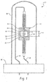
- FIGURE 1 a lamp 10 comprising a ceramic metal halide (CMH) discharge vessel 12 in accordance with the exemplary embodiment is shown.
- FIGURE 1 is intended to be exemplary only.
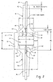
- FIGURE 2 one embodiment of the discharge vessel 12 is shown for illustration.
- the exemplary discharge vessel 12 is suited to use in lamps operating at a variety of wattages, such as about 15-200 watts. By way of example, lamps of 39 and 70 watts are described herein without intending to limit the scope of the invention.
- the wattage of a lamp is typically based on an assumed AC lamp voltage of 95V.
- the lamp 10 is supplied with current by a circuit (not shown) connected with a source of AC power.
- the lamp may be designed to run on an electronic ballast, at higher frequency. Alternatively, the lamp may be run on a DC power source.
- the discharge vessel 12 defines an interior discharge space or chamber 14.
- the discharge vessel 12 includes a high pressure envelope or arc tube 16, formed from a transparent or translucent material, such as polycrystalline alumina or sapphire (single crystal alumina), which is sealed at opposite ends to enclose the discharge space 14.
- the discharge space 14 contains a fill of an ionizable gas mixture 18, such as metal halide and inert gas mixture, which may also include mercury.
- First and second internal electrodes 20, 22, which may be formed entirely or at least partly (>20 wt.%) from tungsten, extend into the discharge space 14.
- a discharge forms in the fill 18 between the electrodes 20, 22 when a voltage is applied across the electrodes.
- the electrodes are connected to conductors 24, 26, formed from molybdenum and niobium sections.
- the conductors 24, 26 electrically connect the electrodes to the external power supply. Tips 28, 30 of the electrodes extend interiorly of a respective interior end wall 32, 34 of the arc tube 16 and are spaced by an arc gap AG of dimension d .
- the discharge vessel 12 may be enclosed in an outer envelope 36 of glass or other suitable transparent or translucent material, which is closed by a lamp cap 38 at one end, although double-ended lamps are also contemplated.
- the lamp may be housed in a reflective housing.
- the exemplary ceramic arc tube 16 includes a hollow cylindrical portion or barrel 40 and two opposed hollow end plugs 42, 44.
- the barrel 40 and end plugs 42, 44 may be formed from separate components that are fused together during formation of the lamp.
- the two end plugs 42, 44 may be similarly shaped and each includes a cone or base portion 46, 48, from which respective hollow leg portions or tubes 50, 52 extend outwardly.
- the electrodes 20, 22 arc seated in bores 54, 56 within their respective leg portions 50, 52 and extend into respective cylindrical follow portions 60, 62, of the cylindrical base portions.
- the cylindrical hollow portions 60, 62 are received in the respective ends of the barrel 40 to create an annular thickened region when the two parts are joined together ( FIG. 2 ).
- An annular rim portion or flange 64, 66 extends radially outward of the respective hollow portion 60, 62 and is sealed to a respective end of the barrel to define the end walls 32, 34 of the discharge space 14.
- the discharge chamber 14 is sealed at the ends of the leg portions 50, 52 by seals (not shown) to create a gas-tight discharge space.
- IBL distance between end walls 32, 34, measured along the lamp axis (mm).
- Exterior barrel length, XBL length of barrel plus flanges (mm).
- Interior Diameter, ID average interior diameter of the barrel in the middle region, intermediate the electrode tips, i.e., away from the cylindrical portions 60, 62 of the end plugs (in mm).
- Wall thickness, t - thickness (mm) of the wall material in the central portion of the arc tube body, e.g., halfway between the electrode tips.
- Arc gap, AG distance between electrode tips 28, 30 at their closest point (mm).
- IA chamber internal surface area in cm 2 .
- WL wall loading, in W/cm 2 of interior wall surface including the end bowls, but excluding legs, and the arctube power (W) is the total arctube power including electrode power.
- the wall loading is from about 11 to 52 W/cm 2 , for example, about 14 to 32 W/cm 2 .
- a wall temperature of the discharge vessel, during operation is no greater than 1460 K..
- a cylindrical lamp as shown which is essentially composed of three cylindrical interior volume portions 70, 72, 74, as shown in FIGURE 3 , where the first and third portions 70, 74 are of height h 1 and interior radius r 1 , and the intermediate portion 72 is of height h 2 and interior radius r 2 , then the total volume of this design is 2 ⁇ r 1 2 h 1 + ⁇ r 2 2 h 2 .
- the lamp barrel is curved (see, e.g., FIG.
- the curvature may be taken into account when computing the volume, e.g., using the SOLIDWORKSTM program.
- This methodology can be applied to any shape of lamp.
- the chamber volume is determined through calculation based on lamp dimensions, although it is also contemplated that for less regularly shaped chambers, the chamber volume may be determined by other means, such as by determining the added weight of the arc tube when filled with water, converting this to an equivalent volume, and subtracting a volume of the water occupying the legs.
- parameters for 39W and 70W lamps may be as shown in TABLE 1: TABLE 1 39W 70W PARAMETER Example range Example Example range Example IBL 6-8.5 mm 7.6 mm 7.5-9 mm 8.6 mm Plug Thickness 0.15-1 mm 0.6 mm 0.6-0.8 mm 0.6 mm ID 5-7 mm 5.7 mm 5.5-6.8 mm 6.6 mm T 0.6-1.2 mm 0.6 mm 1.3-1.7 mm 1.6 mm OD 6.2-9.4 mm 6.9 8-10.5 9.6 mm TTP 0.7-2 mm 1.5 0.7-2.0 mm 1.3 mm AG 3-7 mm 4.7 5.5-6 6 mm AG / ID 0.4-1.4 0.82 0.8-1.1 0.9 IA 1.3-2.6 cm 2 1.73 cm 2 1.7-2.7 cm 2 2.29 cm 2 WL 14-30 w/cm2 22.6 w/cm2 26-40 w/cm 2 30.6 w/cm 2 Halide dose weight 4-14 mg (12-120 mg/c
- the exemplary fill 18 includes a metal halide component or "dose" which includes a halide component comprising one or more metal halides, optionally mercury, and a rare gas, such as argon or xenon.
- the halide component may include halides selected from the following: Group I) metal halides, such as sodium halide; Group 11) metal halides, such as calcium halides; Group III) A halides, such as thallium halides and indium halide, hafnium halides, zirconium halides, rare earth halides, such as halides of Sc, Y, and the lanthanoids, i.e., La, Ce, Pr, Pm, Sm, Eu, Gd, Tb, Dy, Ho, Er, Tm, Yb, Lu, and combinations thereof.
- the halides may be chlorides, bromides, iodides or combinations thereof.
- the halide component includes at least one rare earth halide.
- the rare earth halide(s) may be selected in type and concentration such that in combination with the source of oxygen or oxygen derived therefrom, it forms an unstable oxide in the fill during lamp operation.
- unstable oxide it is meant that the oxide comprising the rare earth element allows available oxygen to exist in the fill during lamp operation.
- Suitable rare earth halides are, according to the invention, selected from the group consisting of lanthanum halides, praseodymium halides, neodymium halides, samarium halides, cerium halides, and combinations thereof.
- the fill is free of all other rare earth halides than these.
- the fill may be free of halides of terbium, dysprosium, holmium, thulium, erbium, ytterbium, yttrium, and lutetium.
- the fill may also be free of other halides which do not form stable oxides, such as scandium and magnesium halides.
- free it is meant that all halides of rare earths other than lanthanum, praseodymium, neodymium, samarium, cerium, (and optionally also scandium and magnesium), account for a total mole fraction of less than 0.001 of the halide component of the fill, and in one embodiment, a mole fraction of less than 0.0001.
- the halide component consists essentially of halides which, to the extent that they form oxides during lamp operation, the oxides formed are unstable oxides which provide available oxygen.
- the rare earth halide includes lanthanum halide.
- the rare earth halide(s) may be present in an amount such that, during lamp operation, in combination with the source of available oxygen, maintains a difference in solubility for tungsten species present in a vapor phase between a wall of the discharge vessel and at least a portion of at least one of the electrodes.
- the rare earth halide(s) may be present in the fill, expressed as a total mole fraction of the halide component of the fill, of at least about 0.009, and in one embodiment, can be up to about 0.2.
- iodides of sodium, thallium, calcium, and lanthanum are the predominant halides included in the fill, with other halides making up no more than a total of 20 mol%, e.g., less than 10 mol%, of the halides in the fill, and in one embodiment, less than 1 mol%.
- the halides may be present in the fill in the following mole fractions, based on the total halides in the fill:
- the fill is free of all rare earth halides other than halides of lanthanum.
- free of rare earth halides other than lanthanum it is meant that other rare earth halides are present at no more that 10% of the lanthanum halide mol%.
- the halide weight (HW), which is the weight (mg) of all the halides in the arc tube 16, can be from about 8.0 to 280 mg/cc, e.g., 43 to 63 mg/cc.
- the discharge vessel 12 encloses a source of available oxygen.
- the oxygen provided by the source aids in the wall cleaning cycle and thus can improve lumen maintenance over the lifetime of the lamp.
- the "available oxygen.” is determined as the moles of oxygen (determined as singlet O rather than O 2 ) per unit volume of arc tube, e.g., in micromoles O per cubic centimeter of lamp volume, determined as described above, abbreviated as ⁇ mol O/cc.
- the oxygen is in a form in which it is capable of taking-part in the wall cleaning cycle at the operating temperature of the lamp. Specifically, it is in a form which is capable of taking place in the wall cleaning cycle.
- the available oxygen makes oxygen available for reaction with other fill components to form WO 2 X 2 , where X is a halide, e.g., WO 2 I 2 , or other tungsten oxyhalide species, at the operating temperature of the lamp.
- X is a halide, e.g., WO 2 I 2 , or other tungsten oxyhalide species
- alumina-based ceramics include oxygen
- the oxygen present is too tightly bound to take part in the wall cleaning cycle, and thus, this is not considered available oxygen.
- the available oxygen is present in the lamp at a concentration of at least 0.1 ⁇ mol O/cc, e.g., at least 0.14 ⁇ mol O/cc , and in one embodiment, at least 0.2 ⁇ mol O/cc or at least 0.3 ⁇ mol O/cm of lamp volume (where lamp volume is determined as described above).
- the oxygen is present at a concentration of at least 0.4 ⁇ mol O/cc.
- the available oxygen is, according to the invention, present at up to 1.5 ⁇ mol O/cc, e.g., up to 1.1 ⁇ mol O/cc, and in specific embodiments, up to 1.0 or 0.9 or 0.8 ⁇ mol O/cc.
- the oxygen is present at a concentration of 0.4 to 0.7 ⁇ mol O/cc.
- the available oxygen is considered to be the maximum available oxygen in the discharge chamber during lamp operation. In one embodiment, the available oxygen is selected to be closer to the upper end of the range to allow for loss of oxygen over time.
- Exemplary sources of oxygen are described in U.S. Application Serial Nos. 11/951,677 ( US2009/0146576 A1 ), 11/951,724 ( US2009/146571 A1 ), and 12/270,216 ( US2009/0146570 A1 ), and include oxides of tungsten.
- oxide of tungsten it is meant any oxidized form of tungsten or combination thereof which includes at least one tungsten oxygen bond.
- oxides of tungsten include oxides and oxyhalides of tungsten and reactants/compounds which react or decompose in the lamp under lamp operating conditions to form tungsten oxide or oxyhalide.
- the oxide of tungsten may have the general formula WO n X m , where n is at least 1, m can be ⁇ 0; and X is a halide as defined above.
- Exemplary oxides of tungsten include WO 3 , WO 2 , and tungsten oxyhalides, such as WO 2 I 2 , and combinations thereof.
- Other sources of available oxygen include free oxygen gas (O 9 ), water, molybdenum oxide, mercury oxide, dioxides of lanthanum, cerium, neodymium, samarium, praseodymium, or combinations thereof.
- the source of available oxygen is present in sufficient amounts to provide available oxygen in the lamp in the amounts described above.
- oxygen can be measured at concentrations as low as 1ppm by an inert gas fusion technique, such as with a LECO oxygen analyzer, available from LECO Corp.
- the oxygen content is determined by analysis of the dose mixture prior to introduction to the lamp (which includes the metal halides and solid oxygen source), e.g., with LECO.
- This is the method used to determine the oxygen added to the lamp, and thus is molar concentration per unit volume, in the example lamps described below.
- This method assumes that the dose mixture is the only source of oxygen. This assumption is accurate provided that oxygen is not added to the discharge vessel in significant amounts from other sources, e.g., through oxidation of the tungsten electrodes or introduction of oxygen gas. The assumption can be validated by measuring the oxygen content of the dose pool after several hours of lamp operation.
- Another way to determine the oxygen content is to prepare a lamp then analyze the dose pool, e.g., by breaking open a lamp and analyzing the lamp contents. This should be done before extended lamp operation takes place, since during lamp operation, oxygen tends to be consumed. Additionally, the lamp should be opened in an oxygen free atmosphere so that atmospheric oxygen does not influence the results.
- EDAX or ESCA may be used to determine the oxygen content. In tests on lamps, the LECO method and EDAX method give reasonable agreement, provided that care is taken in the EDAX method to exclude external sources of oxygen.
- Lumen maintenance of at least 98% or 99% or higher at 1000hrs can be readily achieved by careful control of the available oxygen using a fill which includes iodides of Na, Tl, La, and Ca.
- the optimum oxygen content for lumen maintenance is determined by preparing lamps with different available oxygen concentrations and measuring the lumen maintenance. For example, four or more lamps with different oxygen concentrations are selected which may span an oxygen concentration range of, for example, about 0.1 to about 1:5 micromoles O/cc, or a narrower range within that broader range.
- the lamps are burned in their normal operating position (e.g., vertically or horizontally).
- a plot of oxygen concentration vs. lumen maintenance reveals that the lumen maintenance reaches a maximum, with increasing oxygen, then declines as oxygen concentration continues to increase, as illustrated in FIGURE 5 , where each point represents an average of several lamps.
- an optimal lumen maintenance can be achieved.
- an available oxygen concentration is selected which provides at least a 98% lumen maintenance at 1000hrs.
- the experimental data indicates the peak occurs at 0.54 ⁇ mol O/cc.
- 98% lumen maintenance at 1000 hours can be achieved with a range of 0.25 to 0.865 ⁇ mol O/cc. The higher the desired % lumen maintenance at 1000 hours, the narrower the selected range of ⁇ mol O/cc may be.
- the selected [O] concentration may range from 0.2 to 0.7 ⁇ moles O/cc, e.g., from 0.35 ⁇ moles O/cc to 0.55 ⁇ moles/cc.
- the location of the peak may be determined by finding the intersection between a first line, determined by linear regression through the points on one side of the peak, and a second line, determined by linear regression through the points on the other side of the peak.
- the strength of the fit is determined by the parameter R 2 .
- the oxygen concentration can be selected to provide lumen maintenance of at least 98% or at least 100% of that at 100hrs after 1000hrs.
- the oxygen source is present in sufficient quantity to provide available oxygen in the arc tube during initial lamp operation of from 0.14 to 1.0 micromoles/cc of arc tube volume (with volume measured as described above), the oxygen content being determined from the ppm oxygen concentration output by a LECO analyzer on the dose material.
- halide dose concentration also has some effect on the lumen maintenance, and may also be adjusted to provide an optimum lumen maintenance.
- a molar ratio of total halide O / cc . of arc tube volume in the fill is from 900 to 6000, and in one embodiment, is from about 1000 to 5700.
- the value of this parameter may be selected to provide ⁇ 98 1000hr %LM, e.g., ⁇ 98 1000hr %LM.
- the range of molar ratio total halide O / cc . may be a range or 1000 to 5700, and for 99% 1000hr %LM, from about 1250 to 5150.
- the halide concentration in the fill may be determined, for example, by chemical means such as inductively coupled plasma mass spectrometry (ICP - MS) analysis.
- ICP - MS inductively coupled plasma mass spectrometry
- the exemplary cylindrical barrel portion 40 and end plugs 42, 44 may all be formed from a polycrystalline aluminum oxide ceramic, although other polycrystalline ceramic materials capable of withstanding high wall temperatures up to 1700 to 1900°K, and which are resistant to attack by the fill materials, are also contemplated.
- the ceramic arc tube may be formed from a single component or from multiple components, as disclosed, for example, in above-mentioned U.S. Application Serial Nos. 11/951,67 ( US2009/0146576A1 ) and 12/270,216 ( US2009/0146570 A1 ).
- three main components which constitute the barrel and end plugs of the finished arc tube are separately fabricated, for example, by die pressing, injection molding, or extruding a mixture of a ceramic powder and a binder system into a solid body.
- the assembly is sintered at a high temperature (e.g., at 1850 to 1880°C in a hydrogen atmosphere) to form a gas tight, transparent or translucent arc tube of densely sintered polycrystalline alumina.
- 70W ceramic arc tubes having dimensions, as shown in TABLE 1, and a substantially cylindrical shape, as shown in FIGURE 3 , were formed.
- 39W ceramic arc tubes having dimensions similar to those shown in TABLE 1, and a substantially cylindrical shape or rounded end, as shown in FIGURES 3 and 4 , were formed.
- a dose material which included an oxide of tungsten and halides of Na, TI, La, Ca was introduced and sealed within the lamps.
- the oxygen content of the dose was determined by LECO on a bulk sample and converted to moles O/cc for the arc tubes, based on the number of pellets added and assuming a nominally identical volume of the arc tubes.
- the oxygen content of batches of pellets was varied to provide nominally identical fills other than with respect to Available oxygen.
- the total halide weight was approximately 12.5 mg and for 39 W lamps the total halide weight was approximately 8.3 mg (see Table 2 for actual amounts in micromoles).
- Argon gas was present at a fill pressure or 120 Torr.
- Mercury weight for both 39W and 70W was about 5 mg.
- VBU 0.18 5 39w 9 60.7 5.8 24.5 33.6 6
- VBU 0.18 6 39w 8.7 62.2 5.5 23.5 43.9 9
- VBU 0.18 7 39w 9 60.7 5.8 24.5 33.9 9
- VBD 0.18 8 39w 8.3 64 5.3 22.4 37.1 9 VBD 0.18 9 .70w 6.6 71.1 4.2 18 59.9 22
- VBU 0.26 10 70w 6.6 71.1 4.2 18 59.8 27
- VBU 0.26 11 70w 6.6 71.1 4.2 18 59.8 29
- VBU 0.26 12 70w 6.6 71.1 4.2 18 59.8 20
- VBU 0.26 13 70w 6.6 71.1 4.2 18 59.8 15
- VBU 0.26 14 70w 6.6 71.1 4.2 18 59.8 12 VBU 0.26
- VBU indicates the lamp was burned vertically, base up.
- VBD indicates the lamp was burned vertically, base down.
- HOR indicates that the lamp was burned horizontally.
- TABLE 3 shows the results obtained when the lamps were burned for at least 1000 hours. The results are the average of several lamps (generally at least 4 or 5) in each case for lamps burned vertically with an outer jacket. TABLE 3 Cell Lamp Wattage Micromol. Total Halide Micromol.
- Figure 5 shows a plot of 1000hrs % lumen maintenance vs. moles [O]/cc, derived from these results. As discussed above, 98% 1000hr lumen maintenance can readily be achieved in similar lamps with similar halide concentrations by selecting a molar oxygen concentration within the range prescribed by the dotted lines.
- Figure 6 shows a plot of 1000 hour % lumen maintenance versus the parameter: molar ratio total halide O / cc .
- the experimental data indicates the peak in 1000 hour % lumen maintenance at a molar ratio total halide O / cc of around 2700.
- 98% lumen maintenance at 1000 hours can be achieved with a molar ratio total halide O / cc in a range of 1000 to 5700 (which can be determined, for example, by applying an algorithm for fitting a curve to the points of the graph).
- 99% lumen maintenance at 1000 hours can be achieved with a molar ratio total halide O / cc of about 1250 to 5150.
Landscapes
- Vessels And Coating Films For Discharge Lamps (AREA)
- Discharge Lamp (AREA)
Description
- The present invention relates generally to ceramic arc discharge lamps and more particularly to a discharge lamp in which an oxygen content of the lamp fill during lamp operation is selected to provide a high lumen maintenance.
- Discharge lamps produce light by ionizing a vapor fill material, such as a mixture of rare gases, metal halides, and mercury with an electric arc passing between two electrodes. The electrodes and the fill material are sealed within a translucent or transparent discharge vessel that maintains the pressure of the energized fill material and allows the emitted light to pass through it. The fill material, also known as a "dose," emits a desired spectral energy distribution in response to being excited by the electric arc. For example, halides provide spectral energy distributions that offer a broad choice of light properties, e.g., color temperature, color rendering, and luminous efficiency.
- Conventionally, the discharge vessel in a discharge lamp was formed from a vitreous material such as fused quartz, which was shaped into desired chamber geometries after being heated to a softened state. These lamps are limited in performance by the maximum wall temperature achievable in the quartz discharge vessel.
- Ceramic discharge chambers were developed to operate at higher temperatures for improved color temperatures, color rendering, and luminous efficacies, while significantly reducing reactions with the fill material. One problem with such lamps is that the light output over time (typically expressed as lumen maintenance) tends to diminish due to blackening of the walls of the discharge vessel. The blackening is due to tungsten transported from the electrode to the wall.
- It has been proposed to incorporate a calcium oxide or tungsten oxide oxygen dispenser in the discharge vessel, as disclosed, for example in
WO 99/53522WO 99/53523 US2009/0146570 A1 andUS2009/0146576 A1 disclose high pressure discharge lamps comprising halides and a source of oxygen to reduce blackening of the walls by tungsten from the electrodes. - The exemplary embodiment provides a new and improved metal halide lamp with improved lumen maintenance.
- In accordance with one aspect of the exemplary embodiment, a lamp includes a discharge vessel. Electrodes extend into the discharge vessel. An ionizable fill is sealed within the vessel, the fill including a buffer gas, optionally mercury, and a halide component. The halide components includes a rare earth halide selected from the group consisting of lanthanum, cerium, neodymium, praseodymium, samarium, and combinations thereof. Available oxygen is sealed within the discharge vessel at a concentration of at least 0.1 µmol O/cc.
- In accordance with another aspect of the exemplary embodiment, a lamp includes a discharge vessel. Electrodes extend into the discharge vessel. An ionizable fill is sealed within the vessel, the fill including a buffer gas, optionally mercury, and a halide component, the halide component consisting essentially of halides which, to the extent that they form oxides during lamp operation, the oxides formed are unstable oxides which provide available oxygen. Available oxygen is sealed within the discharge vessel, at a concentration of 0.1-1.5 µmol O/cc.
- In accordance with another aspect of the exemplary embodiment, a method of forming lamps with a high lumen maintenance includes providing a set of ceramic metal halide lamps with a halide fill component and a source of available oxygen, whereby at least three or four lamps of the set differ in their respective available oxygen concentrations to provide lamps covering a range of different available oxygen concentrations within a range of from 0.1 µmol O/cc-1.5 µmol O/cc. The lamps are operated by supplying an electric current to each lamp to generate a discharge in the lamp vessel. A lumen maintenance value for each of the lamps is determined. An optimum oxygen concentration or concentration range is computed, based on the determined lumen maintenance values. Lamps are formed with the computed oxygen concentration or with an oxygen concentration within the computed concentrations range.
- One advantage of at least one embodiment of the present disclosure is the provision of a lamp with improved lumen maintenance.
- Still further advantages will become apparent to those of ordinary skill in the art upon reading and understanding the following detailed description of the preferred embodiments.
-
-
FIGURE 1 is a cross sectional view of a lamp in accordance with the exemplary embodiment; -
FIGURE 2 is an enlarged cross sectional view of the discharge vessel ofFIGURE 1 in accordance with one aspect of the exemplary embodiment; -
FIGURE 3 is an enlarged perspective view of the interior volume of the discharge vessel ofFIGURES 1 and2 ; -
FIGURE 4 is an enlarged perspective view of the interior volume of an alternative discharge vessel with rounded ends; -
FIGURE 5 is a combined plot of 1000hr % lumen maintenance vs. oxygen concentration for 39W and 70W lamps with different oxygen concentrations; and -
FIGURE 6 is a combined plot of 1000hr % lumen maintenance vs. molar ratio [halide/O] per cc for 39W and 70W lamps. - Aspects of the exemplary embodiment relate to a lamp which includes a discharge vessel with an ionizable fill and a source of oxygen sealed therein. The source of oxygen is present in an amount which provides an oxygen concentration in the fill which is selected to optimize lumen maintenance.
- Lumens (1m), as used herein, refer to the SI unit of luminous flux, a measure of the perceived power of light. If a light source emits one candela of luminous intensity into a solid angle of one steradian, the total luminous flux emitted into that solid angle is one lumen. Put another way, an isotropic one-candela light source emits a total luminous flux of exactly 4π lumens. The lumen can be considered as a measure of the total "amount" of visible light emitted. The output of a lamp can be defined in terms of Lumens per Watt (LPW). Lumen maintenance is the ratio of lumens after a given period of lamp operation (e.g., 1000hrs) to the initial lumens (e.g., after 100hrs of operation). The exemplary lamp may have a lumen maintenance of at least 95% or at least 98%, or greater at 1000hrs or at 2000hrs. This may be achieved with a wall temperature of the discharge vessel of no greater than 1460K.
- In various aspects, the lamp is able to simultaneously satisfy photometric targets without compromising targeted lumen maintenance. Some of the photometric properties that are desirable in a lamp design include CRI, CCT, lamp output (e.g., expressed as Lumens/Watt), and dCCy.
- The color rendering index CRI is a measure of the ability of the human eye to distinguish colors by the light of the lamp. The color rendering index Ra, as used herein, is the standard measure used by the Commission Internationale de l'Eclairage (CIE) and refers to the average of the indices for eight standardized colors chosen to be of intermediate saturation and spread throughout a range of hues measured (sometimes referred to as R8). Values are expressed on a scale of 0-100, where 100 represents the value for a black body radiator. The exemplary lamp may have a color rendering index, Ra of at least about 85, and can be up to about 87, or higher.
- The correlated color temperature CCT, as used herein, is the color temperature of a black body radiator which in the perception of the human eye most closely matches the light from the lamp. The exemplary lamp may provide a correlated color temperature (CCT) between about 2700K and about 4500K, e.g., 3000K,
- dCCy is the difference in chromaticity of the color point on the Y axis (CCY), from that of the standard black body curve. The exemplary embodiment may have a dCCy of 0.005 +/- 0.010 with respect to the black body locus, and in one specific embodiment, the lamp lies directly on the black body locus, i.e., dCCy = 0.000.
- All of these ranges may be simultaneously satisfied in the present lamp design. This can be achieved without negatively impacting lamp lumen maintenance.
- With reference to
FIGURE 1 , alamp 10 comprising a ceramic metal halide (CMH)discharge vessel 12 in accordance with the exemplary embodiment is shown.FIGURE 1 is intended to be exemplary only. With reference also toFIGURE 2 , one embodiment of thedischarge vessel 12 is shown for illustration. Theexemplary discharge vessel 12 is suited to use in lamps operating at a variety of wattages, such as about 15-200 watts. By way of example, lamps of 39 and 70 watts are described herein without intending to limit the scope of the invention. The wattage of a lamp is typically based on an assumed AC lamp voltage of 95V. Thelamp 10 is supplied with current by a circuit (not shown) connected with a source of AC power. The lamp may be designed to run on an electronic ballast, at higher frequency. Alternatively, the lamp may be run on a DC power source. - The
discharge vessel 12 defines an interior discharge space orchamber 14. Thedischarge vessel 12 includes a high pressure envelope orarc tube 16, formed from a transparent or translucent material, such as polycrystalline alumina or sapphire (single crystal alumina), which is sealed at opposite ends to enclose thedischarge space 14. Thedischarge space 14 contains a fill of anionizable gas mixture 18, such as metal halide and inert gas mixture, which may also include mercury. - First and second
internal electrodes discharge space 14. A discharge forms in thefill 18 between theelectrodes conductors conductors Tips interior end wall 32, 34 of thearc tube 16 and are spaced by an arc gap AG of dimension d. - The
discharge vessel 12 may be enclosed in an outer envelope 36 of glass or other suitable transparent or translucent material, which is closed by alamp cap 38 at one end, although double-ended lamps are also contemplated. In other embodiments, the lamp may be housed in a reflective housing. - As shown in
FIGURE 2 , the exemplaryceramic arc tube 16 includes a hollow cylindrical portion orbarrel 40 and two opposed hollow end plugs 42, 44. Thebarrel 40 and end plugs 42, 44 may be formed from separate components that are fused together during formation of the lamp. The two end plugs 42, 44 may be similarly shaped and each includes a cone orbase portion tubes electrodes bores respective leg portions cylindrical follow portions 60, 62, of the cylindrical base portions. The cylindricalhollow portions 60, 62 are received in the respective ends of thebarrel 40 to create an annular thickened region when the two parts are joined together (FIG. 2 ). An annular rim portion orflange hollow portion 60, 62 and is sealed to a respective end of the barrel to define theend walls 32, 34 of thedischarge space 14. - The
discharge chamber 14 is sealed at the ends of theleg portions - Various dimensions of the
arc tube 16 will now be defined: - Interior barrel length, IBL=distance between
end walls 32, 34, measured along the lamp axis (mm). - Exterior barrel length, XBL=length of barrel plus flanges (mm).
- Interior Diameter, ID=average interior diameter of the barrel in the middle region, intermediate the electrode tips, i.e., away from the
cylindrical portions 60, 62 of the end plugs (in mm). - Wall thickness, t-=thickness (mm) of the wall material in the central portion of the arc tube body, e.g., halfway between the electrode tips.
- Outside diameter, OD=maximum diameter of the barrel.
- Tip to plug distance TTP=distance between the
tip adjacent end wall 32, 34 (mm). Note IBL =d +2 TTP - Arc gap, AG=distance between
electrode tips - Internal area, IA=chamber internal surface area in cm2.
- WL=wall loading, in W/cm2 of interior wall surface including the end bowls, but excluding legs, and the arctube power (W) is the total arctube power including electrode power. In one embodiment, the wall loading is from about 11 to 52 W/cm2, for example, about 14 to 32 W/cm2. In one embodiment, a wall temperature of the discharge vessel, during operation, is no greater than 1460 K..
- Chamber Volume, Vol. (cc)-interior volume of the chamber, not including the bores. For a cylindrical lamp as shown, which is essentially composed of three cylindrical interior volume portions 70, 72, 74, as shown in
FIGURE 3 , where the first and third portions 70, 74 are of height h1 and interior radius r1, and the intermediate portion 72 is of height h2 and interior radius r2, then the total volume of this design is 2πr1 2h1+πr2 2h2. Where the lamp barrel is curved (see, e.g.,FIG. 4 ), rather than substantially cylindrical, as shown inFIGURES 2 and3 , the curvature may be taken into account when computing the volume, e.g., using the SOLIDWORKS™ program. This methodology can be applied to any shape of lamp. In the examples which follow, the chamber volume is determined through calculation based on lamp dimensions, although it is also contemplated that for less regularly shaped chambers, the chamber volume may be determined by other means, such as by determining the added weight of the arc tube when filled with water, converting this to an equivalent volume, and subtracting a volume of the water occupying the legs. - By way of example, parameters for 39W and 70W lamps may be as shown in TABLE 1:
TABLE 1 39W 70W PARAMETER Example range Example Example range Example IBL 6-8.5 mm 7.6 mm 7.5-9 mm 8.6 mm Plug Thickness 0.15-1 mm 0.6 mm 0.6-0.8 mm 0.6 mm ID 5-7 mm 5.7 mm 5.5-6.8 mm 6.6 mm T 0.6-1.2 mm 0.6 mm 1.3-1.7 mm 1.6 mm OD 6.2-9.4 mm 6.9 8-10.5 9.6 mm TTP 0.7-2 mm 1.5 0.7-2.0 mm 1.3 mm AG 3-7 mm 4.7 5.5-6 6 mm AG/ID 0.4-1.4 0.82 0.8-1.1 0.9 IA 1.3-2.6 cm2 1.73 cm2 1.7-2.7 cm2 2.29 cm2 WL 14-30 w/cm2 22.6 w/cm2 26-40 w/cm2 30.6 w/cm2 Halide dose weight 4-14 mg (12-120 mg/cc) 8.3 mg (47 mg/cc) 4-14 mg (12-80 mg/cc) 12 mg (46.2 mg/cc) Wt. tungsten, expressed as WO3 (mg) 0.003-0.02 0.0043 0.009-0.02 0.0092 Wt oxygen (mg) 0.0007-0.005 0.0009 0.002-0.005 0.0019 Vol 0.12-0.3 cm3 0.18 cm3 0.2-0.4 cm3 0.26 cm3 - The
exemplary fill 18 includes a metal halide component or "dose" which includes a halide component comprising one or more metal halides, optionally mercury, and a rare gas, such as argon or xenon. The halide component may include halides selected from the following: Group I) metal halides, such as sodium halide; Group 11) metal halides, such as calcium halides; Group III) A halides, such as thallium halides and indium halide, hafnium halides, zirconium halides, rare earth halides, such as halides of Sc, Y, and the lanthanoids, i.e., La, Ce, Pr, Pm, Sm, Eu, Gd, Tb, Dy, Ho, Er, Tm, Yb, Lu, and combinations thereof. The halides may be chlorides, bromides, iodides or combinations thereof. - In the embodiment according to the invention,
the halide component includes at least one rare earth halide. The
rare earth halide(s) may be selected in type and concentration such that in combination with the source of oxygen or oxygen derived therefrom, it forms an unstable oxide in the fill during lamp operation. By "unstable oxide" it is meant that the oxide comprising the rare earth element allows available oxygen to exist in the fill during lamp operation. Suitable rare earth halides are, according to the invention,
selected from the group consisting of lanthanum halides, praseodymium halides, neodymium halides, samarium halides, cerium halides, and combinations thereof. In one specific embodiment, the fill is free of all other rare earth halides than these. Specifically, the fill may be free of halides of terbium, dysprosium, holmium, thulium, erbium, ytterbium, yttrium, and lutetium. The fill may also be free of other halides which do not form stable oxides, such as scandium and magnesium halides. By free, it is meant that all halides of rare earths other than lanthanum, praseodymium, neodymium, samarium, cerium, (and optionally also scandium and magnesium), account for a total mole fraction of less than 0.001 of the halide component of the fill, and in one embodiment, a mole fraction of less than 0.0001. In this way the halide component consists essentially of halides which, to the extent that they form oxides during lamp operation, the oxides formed are unstable oxides which provide available oxygen. - In one specific embodiment, the rare earth halide includes lanthanum halide.
- The rare earth halide(s) may be present in an amount such that, during lamp operation, in combination with the source of available oxygen, maintains a difference in solubility for tungsten species present in a vapor phase between a wall of the discharge vessel and at least a portion of at least one of the electrodes.
- The rare earth halide(s) may be present in the fill, expressed as a total mole fraction of the halide component of the fill, of at least about 0.009, and in one embodiment, can be up to about 0.2.
- For example, iodides of sodium, thallium, calcium, and lanthanum are the predominant halides included in the fill, with other halides making up no more than a total of 20 mol%, e.g., less than 10 mol%, of the halides in the fill, and in one embodiment, less than 1 mol%.
- By way of example, the halides may be present in the fill in the following mole fractions, based on the total halides in the fill:
- NaI at least 0.3, e.g., up to 0.8;
- TlI at least 0.01, e,g., at least 0.02, and can be up to 0.06 or up to 0.035;
- LaI3 at least 0.009, such as at least 0.02 or at least 0.07 and can be up to 0.3, e.g., up to 0.13; and
- CaI2 at least 0.09., e.g. up to 0.4, such as up to 0.33.
- In one embodiment, the fill is free of all rare earth halides other than halides of lanthanum. By free of rare earth halides other than lanthanum, it is meant that other rare earth halides are present at no more that 10% of the lanthanum halide mol%.
- The halide weight (HW), which is the weight (mg) of all the halides in the
arc tube 16, can be from about 8.0 to 280 mg/cc, e.g., 43 to 63 mg/cc. - The
discharge vessel 12 encloses a source of available oxygen. The oxygen provided by the source aids in the wall cleaning cycle and thus can improve lumen maintenance over the lifetime of the lamp. - As used herein, the "available oxygen." is determined as the moles of oxygen (determined as singlet O rather than O2) per unit volume of arc tube, e.g., in micromoles O per cubic centimeter of lamp volume, determined as described above, abbreviated as µmol O/cc. To be available means, the oxygen is in a form in which it is capable of taking-part in the wall cleaning cycle at the operating temperature of the lamp. Specifically, it is in a form which is capable of taking place in the wall cleaning cycle. The available oxygen makes oxygen available for reaction with other fill components to form WO2X2, where X is a halide, e.g., WO2I2, or other tungsten oxyhalide species, at the operating temperature of the lamp. Thus, for example, while alumina-based ceramics include oxygen, the oxygen present is too tightly bound to take part in the wall cleaning cycle, and thus, this is not considered available oxygen.
- According to the invention, the available oxygen is
present in the lamp at a concentration of at least
0.1 µmol O/cc, e.g., at least 0.14 µmol O/cc, and in one embodiment, at least 0.2 µmol O/cc or at least 0.3 µmol O/cm of lamp volume (where lamp volume is determined as described above). In one specific embodiment, the oxygen is present at a concentration of at least 0.4 µmol O/cc. The available oxygen is, according to the invention,
present at up to 1.5 µmol O/cc, e.g., up to 1.1 µmol
O/cc, and in specific embodiments, up to 1.0 or 0.9 or 0.8 µmol O/cc. In one specific embodiment, the oxygen is present at a concentration of 0.4 to 0.7 µmol O/cc. - Since available oxygen can diminish over time during lamp operation, the available oxygen is considered to be the maximum available oxygen in the discharge chamber during lamp operation. In one embodiment, the available oxygen is selected to be closer to the upper end of the range to allow for loss of oxygen over time.
- Exemplary sources of oxygen are described in U.S. Application Serial Nos.
11/951,677 US2009/0146576 A1 ),11/951,724 US2009/146571 A1 ), and12/270,216 US2009/0146570 A1 ), and include oxides of tungsten. By oxide of
tungsten, it is meant any oxidized form of tungsten or combination thereof which includes at least one tungsten oxygen bond. Examples of oxides of tungsten include oxides and oxyhalides of tungsten and reactants/compounds which react or decompose in the lamp under lamp operating conditions to form tungsten oxide or oxyhalide. In one embodiment, the oxide of tungsten may have the general formula WOnXm, where n is at least 1, m can be ≥0; and X is a halide as defined above. Exemplary oxides of tungsten include WO3, WO2, and tungsten oxyhalides, such as WO2I2, and combinations thereof. Other sources of available oxygen include free oxygen gas (O9), water, molybdenum oxide, mercury oxide, dioxides of lanthanum, cerium, neodymium, samarium, praseodymium, or combinations thereof. - The source of available oxygen is present in sufficient amounts to provide available oxygen in the lamp in the amounts described above.
- Various methods exist for determining the available oxygen, including inert gas fusion, energy dispersive X-ray analysis (EDAX), and Electron Spectroscopy for Chemical Analysis (ESCA, also known as XPS). For example, oxygen can be measured at concentrations as low as 1ppm by an inert gas fusion technique, such as with a LECO oxygen analyzer, available from LECO Corp.
- In one embodiment, the oxygen content is determined by analysis of the dose mixture prior to introduction to the lamp (which includes the metal halides and solid oxygen source), e.g., with LECO. This is the method used to determine the oxygen added to the lamp, and thus is molar concentration per unit volume, in the example lamps described below. This method assumes that the dose mixture is the only source of oxygen. This assumption is accurate provided that oxygen is not added to the discharge vessel in significant amounts from other sources, e.g., through oxidation of the tungsten electrodes or introduction of oxygen gas. The assumption can be validated by measuring the oxygen content of the dose pool after several hours of lamp operation. It has been found that other sources of oxygen, such as the freshly prepared electrodes, account for a relatively minor portion of the available oxygen content (<about 1% of the total available oxygen) and thus, in the exemplary embodiment, are ignored. If oxidized electrodes are used, the contribution of the oxygen in the electrodes should be taken into account in determining the available oxygen.
- Another way to determine the oxygen content is to prepare a lamp then analyze the dose pool, e.g., by breaking open a lamp and analyzing the lamp contents. This should be done before extended lamp operation takes place, since during lamp operation, oxygen tends to be consumed. Additionally, the lamp should be opened in an oxygen free atmosphere so that atmospheric oxygen does not influence the results. In this method, EDAX or ESCA may be used to determine the oxygen content. In tests on lamps, the LECO method and EDAX method give reasonable agreement, provided that care is taken in the EDAX method to exclude external sources of oxygen.
- Unexpectedly, it has been found that within a narrow range, the available oxygen content has a marked effect on lumen maintenance and further, that even though it is used in the wall cleaning cycle, only a very small amount of oxygen is needed. Lumen maintenance of at least 98% or 99% or higher at 1000hrs can be readily achieved by careful control of the available oxygen using a fill which includes iodides of Na, Tl, La, and Ca.
- It has also been found that the parameter mol O/cc which provides an optimum lumen maintenance is largely independent of the lamp internal volume. Thus, 39W lamps, which are generally smaller in volume than 70W lamps, have approximately the same optimum mol. O/cc for a lamp fill which is otherwise nominally identical, e.g., in terms of mol/cc of the halides. It has also been found that the parameter molar ratio

- In one embodiment, the optimum oxygen content for lumen maintenance is determined by preparing lamps with different available oxygen concentrations and measuring the lumen maintenance. For example, four or more lamps with different oxygen concentrations are selected which may span an oxygen concentration range of, for example, about 0.1 to about 1:5 micromoles O/cc, or a narrower range within that broader range. The lamps are burned in their normal operating position (e.g., vertically or horizontally). A plot of oxygen concentration vs. lumen maintenance reveals that the lumen maintenance reaches a maximum, with increasing oxygen, then declines as oxygen concentration continues to increase, as illustrated in
FIGURE 5 , where each point represents an average of several lamps. By selecting an oxygen content in the peak region, e.g., no more than, for example ±0.3 µmol O/cc from the concentrations at the peak p, and in one embodiment, no more than ±0.25 µmol O/cc from the concentration at the peak p, (equal to 0.54 µmol O/cc inFIG. 5 ), an optimal lumen maintenance can be achieved. In one embodiment, an available oxygen concentration is selected which provides at least a 98% lumen maintenance at 1000hrs. For example, as shown inFigure 5 , the experimental data indicates the peak occurs at 0.54 µmol O/cc. Hence 98% lumen maintenance at 1000 hours can be achieved with a range of 0.25 to 0.865 µmol O/cc. The higher the desired % lumen maintenance at 1000 hours, the narrower the selected range of µmol O/cc may be. - In another example, if the peak is at 0.45 µmoles/cc, the selected [O] concentration may range from 0.2 to 0.7 µmoles O/cc, e.g., from 0.35µmoles O/cc to 0.55 µmoles/cc.
- In one embodiment, the location of the peak may be determined by finding the intersection between a first line, determined by linear regression through the points on one side of the peak, and a second line, determined by linear regression through the points on the other side of the peak. Alternatively, the peak may be found by curve fitting methods, e.g., by best fitting a curve to a polynomial expression, such as the expression y=Ax3+Bx2+Cx+D, where y is in units of 1khr %LM, and x is in units of µmol O/cc, and A, B, C, and D are, constants. The strength of the fit is determined by the parameter R2.
- For example, the oxygen concentration can be selected to provide lumen maintenance of at least 98% or at least 100% of that at 100hrs after 1000hrs.
- In one embodiment, the oxygen source is present in sufficient quantity to provide available oxygen in the arc tube during initial lamp operation of from 0.14 to 1.0 micromoles/cc of arc tube volume (with volume measured as described above), the oxygen content being determined from the ppm oxygen concentration output by a LECO analyzer on the dose material.
- Results for lumen maintenance beyond 1000hrs may drop as oxygen is consumed. For example, for a 70W lamp with O µmoles/cc formed as above, the following results may be obtained.
1kh%LM 101.1 2kh%LM 98.2 3kh%LM 94.9 - It is to be noted that halide dose concentration also has some effect on the lumen maintenance, and may also be adjusted to provide an optimum lumen maintenance. In the embodiment according to the invention,
a molar ratio of
900 to 6000, and in one embodiment, is from about 1000 to 5700. As for the O concentration, the value of this parameter may be selected to provide ≥98 1000hr %LM, e.g., ≥98 1000hr %LM. Thus for Example, for a lamp to achieve 98% lumen maintenance at 1000 hours, the range of molar ratio
- The halide concentration in the fill may be determined, for example, by chemical means such as inductively coupled plasma mass spectrometry (ICP - MS) analysis.
- The exemplary
cylindrical barrel portion 40 and end plugs 42, 44 may all be formed from a polycrystalline aluminum oxide ceramic, although other polycrystalline ceramic materials capable of withstanding high wall temperatures up to 1700 to 1900°K, and which are resistant to attack by the fill materials, are also contemplated. The ceramic arc tube may be formed from a single component or from multiple components, as disclosed, for example, in above-mentioned U.S. Application Serial Nos.11/951,67 (US2009/0146576A1 ) and12/270,216 US2009/0146570 A1 ). For example,
three main components which constitute the barrel and end plugs of the finished arc tube are separately fabricated, for example, by die pressing, injection molding, or extruding a mixture of a ceramic powder and a binder system into a solid body. After assembly of the fired parts, the assembly is sintered at a high temperature (e.g., at 1850 to 1880°C in a hydrogen atmosphere) to form a gas tight, transparent or translucent arc tube of densely sintered polycrystalline alumina. - Without intending to limit the exemplary embodiment, the following Examples demonstrate the performance of the exemplary lamp.
- 70W ceramic arc tubes having dimensions, as shown in TABLE 1, and a substantially cylindrical shape, as shown in
FIGURE 3 , were formed. 39W ceramic arc tubes having dimensions similar to those shown in TABLE 1, and a substantially cylindrical shape or rounded end, as shown inFIGURES 3 and4 , were formed. A dose material which included an oxide of tungsten and halides of Na, TI, La, Ca was introduced and sealed within the lamps. The oxygen content of the dose was determined by LECO on a bulk sample and converted to moles O/cc for the arc tubes, based on the number of pellets added and assuming a nominally identical volume of the arc tubes. The oxygen content of batches of pellets was varied to provide nominally identical fills other than with respect to Available oxygen. - For 70W lamps, the total halide weight was approximately 12.5 mg and for 39 W lamps the total halide weight was approximately 8.3 mg (see Table 2 for actual amounts in micromoles). Argon gas was present at a fill pressure or 120 Torr. Mercury weight for both 39W and 70W was about 5 mg.
- For the 70W lamps, dose weights and dose mole fractions were approximately as follow, with exact amounts given in TABLE 2:
Nal 6.4 mg (70.8 mol% of halide component) TlI 0.8 mg (4.3 mol% of halide component) LaI3 2.1 mg (18.2 mol% of halide component) CaI2 3.2 mg (6.7 mol% of halide component) - TABLE 2 summarizes the properties of the lamps tested for 70W and 39W lamps.
TABLE 2 Cell Lamp Wattage LaI3 mol% NaI mol% TlI mol% CaI2 mol% Total Halide in lamp (micromol.) No of lamps Burn Orientation Vol (cm3) 1 39w 6.7 71 4.3 18.1 38.3 4 VBU 0.18 2 39w 7 71 4 18 43.5 15 HOR 0.11 3 39w 6 74 4 16 38.2 13 HOR 0.11 4 39w 7.8 66.1 5 21.1 45.3 7 VBU. 0.18 5 39w 9 60.7 5.8 24.5 33.6 6 VBU 0.18 6 39w 8.7 62.2 5.5 23.5 43.9 9 VBU 0.18 7 39w 9 60.7 5.8 24.5 33.9 9 VBD 0.18 8 39w 8.3 64 5.3 22.4 37.1 9 VBD 0.18 9 .70w 6.6 71.1 4.2 18 59.9 22 VBU 0.26 10 70w 6.6 71.1 4.2 18 59.8 27 VBU 0.26 11 70w 6.6 71.1 4.2 18 59.8 29 VBU 0.26 12 70w 6.6 71.1 4.2 18 59.8 20 VBU 0.26 13 70w 6.6 71.1 4.2 18 59.8 15 VBU 0.26 14 70w 6.6 71.1 4.2 18 59.8 12 VBU 0.26 - For the 39W lamps, several different lamp structures were used, including rounded end lamps, as illustrated in
Figure 4 , reflected in the different lamp volumes. VBU indicates the lamp was burned vertically, base up. VBD indicates the lamp was burned vertically, base down. HOR indicates that the lamp was burned horizontally. - TABLE 3 shows the results obtained when the lamps were burned for at least 1000 hours. The results are the average of several lamps (generally at least 4 or 5) in each case for lamps burned vertically with an outer jacket.
TABLE 3 Cell Lamp Wattage Micromol. Total Halide Micromol. Total O molar ratio [Halide/O]/cc Average 1000 hrs % Lumen maintenance 1 39w 38.3 0.055 3923.7 100.7 2 39w 43.5 0.074 5613.7 101.0 3 39w 38.2 0.074 4935.4 99.9 4 39w 45.3 0.055 4638.6 96.9 5 39w 33.6 0.023 8255.3 94.0 6 39w 43.9 0.037 6741.4 94.0 7 39w 33.9 0.023 8336.1 94.5 8 39w 37.1 0.037 5694.2 99.2 9 70w 59.9 0.237 974.6 97.5 10 70w 59.8 0.121 1910.8 101.1 11 70w 59.8 0.121 1910.8 101.2 12 70w 59.8 0.121 1910.8 101.8 13 70w 59.8 0.118 1945.5 101.6 14 70w 59.8 0.187 1229.9 98.5 -
Figure 5 shows a plot of 1000hrs % lumen maintenance vs. moles [O]/cc, derived from these results. As discussed above, 98% 1000hr lumen maintenance can readily be achieved in similar lamps with similar halide concentrations by selecting a molar oxygen concentration within the range prescribed by the dotted lines. -
Figure 6 shows a plot of 1000 hour % lumen maintenance versus the parameter: molar ratio
- As shown in
Figure 6 , the experimental data, as constructed from TABLES 2 and 3, indicates the peak in 1000 hour % lumen maintenance at a molar ratio


- The higher the desired % lumen maintenance at 1000 hours, the narrower the required range of molar ratio

- The invention has been described with reference to the preferred embodiments. Obviously, modifications and alterations will occur to others upon reading and understanding the preceding detailed description. It is intended that the invention be construed as including all such modifications and alterations falling within the scope of the appended claims.
Claims (13)
- A lamp (10) comprising:a discharge vessel (12);electrodes (20,22) extending into the discharge vessel (12);an ionizable fill (18) sealed within the vessel (12), the fill (18) comprising:a buffer gas,optionally mercury, anda halide component, the halide component including a rare earth halide selected from the group consisting of lanthanum halides, cerium halides, neodymium halides, praseodymium halides, samarium halides, and combinations thereof;available oxygen, sealed within the vesselat a concentration of at least 0.1 µmol
O/cc and up to 1.5 µmol O/cc; characterized in thata ratio of
- The lamp 10) of claim 1, wherein the available oxygen is at a concentration of at least 0.14 µmol O/cc, and preferably at a concentration of at least 0.3 µmol O/cc.
- The lamp (10) of claim 1, wherein the available oxygen is at a concentration of up to 1.0 µmol O/cc.
- The lamp (10) of claim 1, wherein the available oxygen is at a concentration that provides a lumen maintenance at 1000hrs, expressed as a percentage of lumens at 100 hrs, of at least 98%, and preferably at least 99%.
- The lamp (10) of any one of claims 1 to 4, wherein the halide component includes at least one source of iodine.
- The lamp (10) of any one of claims 1 to 5, wherein the halide component comprises a sodium halide, a lanthanum halide, a thallium halide, and/or a calcium Halide.
- The lamp (10) of claim 6, wherein the lanthanum halide is present in the halide component at a mol. fraction of at least 0.009, and preferably at a mol. fraction of up to 0.3.
- The lamp (10) of claim 6, wherein the sodium halide is present in the halide component at a mol fraction of at least 0.3, and preferably at a mol fraction of at least 0.01.
- The lamp (10) of claim 6, wherein the calcium halide is present in the halide component at a mol fraction of at least 0.09.
- The lamp (10) of any one of claims 1 to 9, wherein the halide component is free of all rare earth halides other than halides of lanthanum, cerium, neodymium, praseodymium, and samarium.
- The lamp (10) of claim 10, wherein the fill is free of all rare earth halides other than halides of lanthanum.
- The lamp (10) of claim 1, wherein the molar ratio of

- A method of operating a lamp (10) comprising:providing the lamp (10) of any one of claims 1 to 12;operating the lamp (10) by supplying an electric current to the lamp (10) to generate a discharge in the lamp vessel (12), wherein in operation, the lamp (10) operates at a 1000hr % lumen maintenance of at least 98.
Applications Claiming Priority (2)
| Application Number | Priority Date | Filing Date | Title |
|---|---|---|---|
| US12/568,108 US8653732B2 (en) | 2007-12-06 | 2009-09-28 | Ceramic metal halide lamp with oxygen content selected for high lumen maintenance |
| PCT/US2010/042679 WO2011037676A1 (en) | 2009-09-28 | 2010-07-21 | Ceramic metal halide lamp with oxygen content selected for high lumen maintenance |
Publications (2)
| Publication Number | Publication Date |
|---|---|
| EP2483912A1 EP2483912A1 (en) | 2012-08-08 |
| EP2483912B1 true EP2483912B1 (en) | 2016-07-20 |
Family
ID=43034662
Family Applications (1)
| Application Number | Title | Priority Date | Filing Date |
|---|---|---|---|
| EP10737200.5A Not-in-force EP2483912B1 (en) | 2009-09-28 | 2010-07-21 | Ceramic metal halide lamp with oxygen content selected for high lumen maintenance |
Country Status (6)
| Country | Link |
|---|---|
| US (1) | US8653732B2 (en) |
| EP (1) | EP2483912B1 (en) |
| KR (1) | KR101779223B1 (en) |
| CN (1) | CN102549708B (en) |
| BR (1) | BR112012006749A2 (en) |
| WO (1) | WO2011037676A1 (en) |
Families Citing this family (10)
| Publication number | Priority date | Publication date | Assignee | Title |
|---|---|---|---|---|
| US8207674B2 (en) * | 2008-02-18 | 2012-06-26 | General Electric Company | Dose composition suitable for low wattage ceramic metal halide lamp |
| CN102985997A (en) * | 2010-07-09 | 2013-03-20 | 欧司朗股份有限公司 | High-pressure discharge lamp |
| US8482202B2 (en) * | 2010-09-08 | 2013-07-09 | General Electric Company | Thallium iodide-free ceramic metal halide lamp |
| CN101976994A (en) * | 2010-09-17 | 2011-02-16 | 三一重工股份有限公司 | Conversion circuit, method and system for detecting phase sequence of three-phase power supply, and motor |
| DE102011077302A1 (en) * | 2011-06-09 | 2012-12-13 | Osram Ag | High pressure discharge lamp |
| US8497633B2 (en) | 2011-07-20 | 2013-07-30 | General Electric Company | Ceramic metal halide discharge lamp with oxygen content and metallic component |
| AU2011373791B2 (en) * | 2011-07-26 | 2015-01-15 | Iwasaki Electric Co., Ltd. | Metal Halide Lamp and Lighting Apparatus |
| US8482198B1 (en) | 2011-12-19 | 2013-07-09 | General Electric Company | High intensity discharge lamp with improved startability and performance |
| US20150015144A1 (en) * | 2013-07-09 | 2015-01-15 | General Electric Company | High efficiency ceramic lamp |
| US9437615B2 (en) | 2014-06-04 | 2016-09-06 | General Electric Company | High intensity discharge lamps with dosing aid |
Family Cites Families (43)
| Publication number | Priority date | Publication date | Assignee | Title |
|---|---|---|---|---|
| US4005324A (en) * | 1976-03-17 | 1977-01-25 | General Motors Corporation | Tungsten-fluorine lamp with native retained oxygen therein and method of manufacture |
| JPS57128446A (en) | 1981-01-30 | 1982-08-10 | Toshiba Corp | Metal halide lamp |
| US4390811A (en) | 1981-03-16 | 1983-06-28 | Gte Products Corporation | High intensity discharge lamp including arc extinguishing means |
| US4943523A (en) | 1984-01-30 | 1990-07-24 | Enzo Biochem, Inc. | Detectable molecules, method of preparation and use |
| US4825124A (en) | 1984-05-07 | 1989-04-25 | Gte Laboratories Incorporated | Phosphor particle, fluorescent lamp, and manufacturing method |
| US4710674A (en) | 1984-05-07 | 1987-12-01 | Gte Laboratories Incorporated | Phosphor particle, fluorescent lamp, and manufacturing method |
| US5196234A (en) | 1986-08-29 | 1993-03-23 | Gte Products Corporation | Method for preparing zinc orthosilicate phosphor particle |
| US5013968A (en) | 1989-03-10 | 1991-05-07 | General Electric Company | Reprographic metal halide lamps having long life and maintenance |
| US5159229A (en) | 1989-06-06 | 1992-10-27 | Gte Products Corporation | Metal halide lamp having CO in gas fill |
| US5111108A (en) | 1990-12-14 | 1992-05-05 | Gte Products Corporation | Vapor discharge device with electron emissive material |
| DE4327534A1 (en) | 1993-08-16 | 1995-02-23 | Patent Treuhand Ges Fuer Elektrische Gluehlampen Mbh | Metal halide discharge lamp for photo-optical purposes |
| US5708324A (en) | 1996-03-18 | 1998-01-13 | Matsushita Research And Development Laboratory Inc. | Fluorescent lamp with different density phosphor coatings on the front panel and internal channels |
| IT1285988B1 (en) | 1996-11-22 | 1998-06-26 | Getters Spa | OXYGEN DISPENSER FOR HIGH PRESSURE DISCHARGE LAMPS |
| EP0902964B1 (en) | 1997-02-24 | 2003-09-03 | Koninklijke Philips Electronics N.V. | A high-pressure metal halide lamp |
| JP3626324B2 (en) | 1997-05-13 | 2005-03-09 | ウシオ電機株式会社 | Manufacturing method of ceramic discharge lamp |
| JP2002503387A (en) | 1997-06-04 | 2002-01-29 | フュージョン ライティング,インコーポレイテッド | Method and apparatus for an improved electrodeless lamp screen |
| CA2255983C (en) | 1997-12-16 | 2007-10-23 | Konoshima Chemical Co., Ltd. | A corrosion resistant ceramic and a production method thereof |
| TW403819B (en) | 1998-04-08 | 2000-09-01 | Koninkl Philips Electronics Nv | High-pressure metal-halide lamp |
| TW385479B (en) | 1998-04-08 | 2000-03-21 | Koninkl Philips Electronics Nv | Metal-halide lamp |
| US6210605B1 (en) | 1999-07-26 | 2001-04-03 | General Electric Company | Mn2+ activated green emitting SrAL12O19 luminiscent material |
| US6586878B1 (en) | 1999-12-16 | 2003-07-01 | Koninklijke Philips Electronics N.V. | Metal halide lamp with improved getter orientation |
| US6713027B2 (en) | 2001-08-24 | 2004-03-30 | Electroclave | Ozonator for sterilizing, decontaminating, disinfecting, and/or sanitizing surgical instruments |
| JP3555889B2 (en) * | 2001-12-20 | 2004-08-18 | Necライティング株式会社 | High pressure discharge lamp and method of manufacturing the same |
| JP2005534139A (en) | 2002-01-15 | 2005-11-10 | コーニンクレッカ フィリップス エレクトロニクス エヌ ヴィ | Metal halide lamp |
| JP3800166B2 (en) | 2002-11-01 | 2006-07-26 | ウシオ電機株式会社 | Discharge lamp |
| JP2006508502A (en) | 2002-11-08 | 2006-03-09 | アドバンスド ライティング テクノロジイズ,インコーポレイティド | Barrier coating and method in a discharge lamp |
| JP2004303573A (en) * | 2003-03-31 | 2004-10-28 | Matsushita Electric Ind Co Ltd | High pressure mercury lamp, lamp unit using this high pressure mercury lamp, and image display device using this lamp unit |
| US20070149496A1 (en) | 2003-10-31 | 2007-06-28 | Jack Tuszynski | Water-soluble compound |
| US20080119421A1 (en) | 2003-10-31 | 2008-05-22 | Jack Tuszynski | Process for treating a biological organism |
| JP2005183248A (en) | 2003-12-22 | 2005-07-07 | Matsushita Electric Ind Co Ltd | Metal halide lamp and lighting device using the same |
| CN100583379C (en) * | 2004-01-15 | 2010-01-20 | 皇家飞利浦电子股份有限公司 | High pressure mercury vapor lamp |
| US20050249667A1 (en) | 2004-03-24 | 2005-11-10 | Tuszynski Jack A | Process for treating a biological organism |
| US20050215764A1 (en) | 2004-03-24 | 2005-09-29 | Tuszynski Jack A | Biological polymer with differently charged portions |
| US7057350B2 (en) | 2004-05-05 | 2006-06-06 | Matsushita Electric Industrial Co. Ltd. | Metal halide lamp with improved lumen value maintenance |
| US7414368B2 (en) * | 2005-01-21 | 2008-08-19 | General Electric Company | Ceramic metal halide lamp with cerium-containing fill |
| US7268495B2 (en) * | 2005-01-21 | 2007-09-11 | General Electric Company | Ceramic metal halide lamp |
| DE202005005200U1 (en) * | 2005-04-01 | 2006-08-10 | Patent-Treuhand-Gesellschaft für elektrische Glühlampen mbH | metal halide |
| US20070085478A1 (en) | 2005-10-13 | 2007-04-19 | General Electric Company | High pressure alkali metal discharge lamp |
| US8585753B2 (en) | 2006-03-04 | 2013-11-19 | John James Scanlon | Fibrillated biodegradable prosthesis |
| US20080299177A1 (en) | 2007-06-06 | 2008-12-04 | Biovaluation & Analysis, Inc. | Supramolecular Complexes for Use in Acoustically Mediated Intracellular Drug Delivery in vivo |
| US20090146571A1 (en) | 2007-12-06 | 2009-06-11 | Russell Timothy D | Metal halide lamp with halogen-promoted wall cleaning cycle |
| US8358070B2 (en) | 2007-12-06 | 2013-01-22 | General Electric Company | Lanthanide oxide as an oxygen dispenser in a metal halide lamp |
| US7868553B2 (en) | 2007-12-06 | 2011-01-11 | General Electric Company | Metal halide lamp including a source of available oxygen |
-
2009
- 2009-09-28 US US12/568,108 patent/US8653732B2/en not_active Expired - Fee Related
-
2010
- 2010-07-21 BR BR112012006749-4A patent/BR112012006749A2/en not_active Application Discontinuation
- 2010-07-21 EP EP10737200.5A patent/EP2483912B1/en not_active Not-in-force
- 2010-07-21 WO PCT/US2010/042679 patent/WO2011037676A1/en not_active Ceased
- 2010-07-21 KR KR1020127010927A patent/KR101779223B1/en not_active Expired - Fee Related
- 2010-07-21 CN CN201080044684.5A patent/CN102549708B/en not_active Expired - Fee Related
Also Published As
| Publication number | Publication date |
|---|---|
| BR112012006749A2 (en) | 2020-08-11 |
| EP2483912A1 (en) | 2012-08-08 |
| US20100013417A1 (en) | 2010-01-21 |
| CN102549708A (en) | 2012-07-04 |
| US8653732B2 (en) | 2014-02-18 |
| KR101779223B1 (en) | 2017-09-18 |
| KR20120091148A (en) | 2012-08-17 |
| WO2011037676A1 (en) | 2011-03-31 |
| CN102549708B (en) | 2015-11-25 |
Similar Documents
| Publication | Publication Date | Title |
|---|---|---|
| US8653732B2 (en) | Ceramic metal halide lamp with oxygen content selected for high lumen maintenance | |
| EP1844488B1 (en) | Ceramic metal halide lamp | |
| US7268495B2 (en) | Ceramic metal halide lamp | |
| JP4262968B2 (en) | Ceramic metal halide lamp | |
| EP2229687B1 (en) | Metal halide lamp including a source of available oxygen | |
| EP2145347B1 (en) | Metal halide lamp comprising an ionisable salt filling | |
| US8358070B2 (en) | Lanthanide oxide as an oxygen dispenser in a metal halide lamp | |
| US20050194908A1 (en) | Ceramic metal halide lamp with optimal shape | |
| US8350477B2 (en) | Ceramic metal halide lamp with length to diameter ratio | |
| US8207674B2 (en) | Dose composition suitable for low wattage ceramic metal halide lamp | |
| EP1134776A2 (en) | High pressure mercury vapour discharge lamp with reduced sensitivity to variations in operating parameters | |
| US8497633B2 (en) | Ceramic metal halide discharge lamp with oxygen content and metallic component | |
| US8339044B2 (en) | Mercury-free ceramic metal halide lamp with improved lumen run-up | |
| MX2008007587A (en) | Ceramic metal halide lamp |
Legal Events
| Date | Code | Title | Description |
|---|---|---|---|
| PUAI | Public reference made under article 153(3) epc to a published international application that has entered the european phase |
Free format text: ORIGINAL CODE: 0009012 |
|
| 17P | Request for examination filed |
Effective date: 20120502 |
|
| AK | Designated contracting states |
Kind code of ref document: A1 Designated state(s): AL AT BE BG CH CY CZ DE DK EE ES FI FR GB GR HR HU IE IS IT LI LT LU LV MC MK MT NL NO PL PT RO SE SI SK SM TR |
|
| DAX | Request for extension of the european patent (deleted) | ||
| 17Q | First examination report despatched |
Effective date: 20140121 |
|
| GRAP | Despatch of communication of intention to grant a patent |
Free format text: ORIGINAL CODE: EPIDOSNIGR1 |
|
| RIC1 | Information provided on ipc code assigned before grant |
Ipc: H01J 61/30 20060101ALN20160218BHEP Ipc: H01J 61/82 20060101ALI20160218BHEP Ipc: H01J 61/26 20060101ALN20160218BHEP Ipc: H01J 61/12 20060101AFI20160218BHEP |
|
| INTG | Intention to grant announced |
Effective date: 20160301 |
|
| GRAS | Grant fee paid |
Free format text: ORIGINAL CODE: EPIDOSNIGR3 |
|
| GRAA | (expected) grant |
Free format text: ORIGINAL CODE: 0009210 |
|
| AK | Designated contracting states |
Kind code of ref document: B1 Designated state(s): AL AT BE BG CH CY CZ DE DK EE ES FI FR GB GR HR HU IE IS IT LI LT LU LV MC MK MT NL NO PL PT RO SE SI SK SM TR |
|
| REG | Reference to a national code |
Ref country code: GB Ref legal event code: FG4D |
|
| REG | Reference to a national code |
Ref country code: CH Ref legal event code: EP |
|
| REG | Reference to a national code |
Ref country code: IE Ref legal event code: FG4D |
|
| REG | Reference to a national code |
Ref country code: AT Ref legal event code: REF Ref document number: 814678 Country of ref document: AT Kind code of ref document: T Effective date: 20160815 |
|
| REG | Reference to a national code |
Ref country code: DE Ref legal event code: R096 Ref document number: 602010034849 Country of ref document: DE |
|
| REG | Reference to a national code |
Ref country code: FR Ref legal event code: PLFP Year of fee payment: 7 |
|
| REG | Reference to a national code |
Ref country code: NL Ref legal event code: FP |
|
| REG | Reference to a national code |
Ref country code: LT Ref legal event code: MG4D |
|
| REG | Reference to a national code |
Ref country code: AT Ref legal event code: MK05 Ref document number: 814678 Country of ref document: AT Kind code of ref document: T Effective date: 20160720 |
|
| PG25 | Lapsed in a contracting state [announced via postgrant information from national office to epo] |
Ref country code: BE Free format text: LAPSE BECAUSE OF NON-PAYMENT OF DUE FEES Effective date: 20160731 |
|
| PG25 | Lapsed in a contracting state [announced via postgrant information from national office to epo] |
Ref country code: FI Free format text: LAPSE BECAUSE OF FAILURE TO SUBMIT A TRANSLATION OF THE DESCRIPTION OR TO PAY THE FEE WITHIN THE PRESCRIBED TIME-LIMIT Effective date: 20160720 Ref country code: IS Free format text: LAPSE BECAUSE OF FAILURE TO SUBMIT A TRANSLATION OF THE DESCRIPTION OR TO PAY THE FEE WITHIN THE PRESCRIBED TIME-LIMIT Effective date: 20161120 Ref country code: IT Free format text: LAPSE BECAUSE OF FAILURE TO SUBMIT A TRANSLATION OF THE DESCRIPTION OR TO PAY THE FEE WITHIN THE PRESCRIBED TIME-LIMIT Effective date: 20160720 Ref country code: HR Free format text: LAPSE BECAUSE OF FAILURE TO SUBMIT A TRANSLATION OF THE DESCRIPTION OR TO PAY THE FEE WITHIN THE PRESCRIBED TIME-LIMIT Effective date: 20160720 Ref country code: NO Free format text: LAPSE BECAUSE OF FAILURE TO SUBMIT A TRANSLATION OF THE DESCRIPTION OR TO PAY THE FEE WITHIN THE PRESCRIBED TIME-LIMIT Effective date: 20161020 Ref country code: LT Free format text: LAPSE BECAUSE OF FAILURE TO SUBMIT A TRANSLATION OF THE DESCRIPTION OR TO PAY THE FEE WITHIN THE PRESCRIBED TIME-LIMIT Effective date: 20160720 |
|
| PG25 | Lapsed in a contracting state [announced via postgrant information from national office to epo] |
Ref country code: BE Free format text: LAPSE BECAUSE OF FAILURE TO SUBMIT A TRANSLATION OF THE DESCRIPTION OR TO PAY THE FEE WITHIN THE PRESCRIBED TIME-LIMIT Effective date: 20160720 Ref country code: AT Free format text: LAPSE BECAUSE OF FAILURE TO SUBMIT A TRANSLATION OF THE DESCRIPTION OR TO PAY THE FEE WITHIN THE PRESCRIBED TIME-LIMIT Effective date: 20160720 Ref country code: GR Free format text: LAPSE BECAUSE OF FAILURE TO SUBMIT A TRANSLATION OF THE DESCRIPTION OR TO PAY THE FEE WITHIN THE PRESCRIBED TIME-LIMIT Effective date: 20161021 Ref country code: ES Free format text: LAPSE BECAUSE OF FAILURE TO SUBMIT A TRANSLATION OF THE DESCRIPTION OR TO PAY THE FEE WITHIN THE PRESCRIBED TIME-LIMIT Effective date: 20160720 Ref country code: PT Free format text: LAPSE BECAUSE OF FAILURE TO SUBMIT A TRANSLATION OF THE DESCRIPTION OR TO PAY THE FEE WITHIN THE PRESCRIBED TIME-LIMIT Effective date: 20161121 Ref country code: SE Free format text: LAPSE BECAUSE OF FAILURE TO SUBMIT A TRANSLATION OF THE DESCRIPTION OR TO PAY THE FEE WITHIN THE PRESCRIBED TIME-LIMIT Effective date: 20160720 Ref country code: LV Free format text: LAPSE BECAUSE OF FAILURE TO SUBMIT A TRANSLATION OF THE DESCRIPTION OR TO PAY THE FEE WITHIN THE PRESCRIBED TIME-LIMIT Effective date: 20160720 Ref country code: PL Free format text: LAPSE BECAUSE OF FAILURE TO SUBMIT A TRANSLATION OF THE DESCRIPTION OR TO PAY THE FEE WITHIN THE PRESCRIBED TIME-LIMIT Effective date: 20160720 |
|
| REG | Reference to a national code |
Ref country code: CH Ref legal event code: PL |
|
| REG | Reference to a national code |
Ref country code: DE Ref legal event code: R097 Ref document number: 602010034849 Country of ref document: DE |
|
| PG25 | Lapsed in a contracting state [announced via postgrant information from national office to epo] |
Ref country code: EE Free format text: LAPSE BECAUSE OF FAILURE TO SUBMIT A TRANSLATION OF THE DESCRIPTION OR TO PAY THE FEE WITHIN THE PRESCRIBED TIME-LIMIT Effective date: 20160720 Ref country code: LI Free format text: LAPSE BECAUSE OF NON-PAYMENT OF DUE FEES Effective date: 20160731 Ref country code: CH Free format text: LAPSE BECAUSE OF NON-PAYMENT OF DUE FEES Effective date: 20160731 Ref country code: MC Free format text: LAPSE BECAUSE OF FAILURE TO SUBMIT A TRANSLATION OF THE DESCRIPTION OR TO PAY THE FEE WITHIN THE PRESCRIBED TIME-LIMIT Effective date: 20160720 Ref country code: RO Free format text: LAPSE BECAUSE OF FAILURE TO SUBMIT A TRANSLATION OF THE DESCRIPTION OR TO PAY THE FEE WITHIN THE PRESCRIBED TIME-LIMIT Effective date: 20160720 |
|
| REG | Reference to a national code |
Ref country code: IE Ref legal event code: MM4A |
|
| PLBE | No opposition filed within time limit |
Free format text: ORIGINAL CODE: 0009261 |
|
| STAA | Information on the status of an ep patent application or granted ep patent |
Free format text: STATUS: NO OPPOSITION FILED WITHIN TIME LIMIT |
|
| PG25 | Lapsed in a contracting state [announced via postgrant information from national office to epo] |
Ref country code: BG Free format text: LAPSE BECAUSE OF FAILURE TO SUBMIT A TRANSLATION OF THE DESCRIPTION OR TO PAY THE FEE WITHIN THE PRESCRIBED TIME-LIMIT Effective date: 20161020 Ref country code: CZ Free format text: LAPSE BECAUSE OF FAILURE TO SUBMIT A TRANSLATION OF THE DESCRIPTION OR TO PAY THE FEE WITHIN THE PRESCRIBED TIME-LIMIT Effective date: 20160720 Ref country code: SK Free format text: LAPSE BECAUSE OF FAILURE TO SUBMIT A TRANSLATION OF THE DESCRIPTION OR TO PAY THE FEE WITHIN THE PRESCRIBED TIME-LIMIT Effective date: 20160720 Ref country code: DK Free format text: LAPSE BECAUSE OF FAILURE TO SUBMIT A TRANSLATION OF THE DESCRIPTION OR TO PAY THE FEE WITHIN THE PRESCRIBED TIME-LIMIT Effective date: 20160720 Ref country code: SM Free format text: LAPSE BECAUSE OF FAILURE TO SUBMIT A TRANSLATION OF THE DESCRIPTION OR TO PAY THE FEE WITHIN THE PRESCRIBED TIME-LIMIT Effective date: 20160720 |
|
| 26N | No opposition filed |
Effective date: 20170421 |
|
| REG | Reference to a national code |
Ref country code: FR Ref legal event code: PLFP Year of fee payment: 8 |
|
| PG25 | Lapsed in a contracting state [announced via postgrant information from national office to epo] |
Ref country code: IE Free format text: LAPSE BECAUSE OF NON-PAYMENT OF DUE FEES Effective date: 20160721 |
|
| PG25 | Lapsed in a contracting state [announced via postgrant information from national office to epo] |
Ref country code: LU Free format text: LAPSE BECAUSE OF NON-PAYMENT OF DUE FEES Effective date: 20160721 Ref country code: SI Free format text: LAPSE BECAUSE OF FAILURE TO SUBMIT A TRANSLATION OF THE DESCRIPTION OR TO PAY THE FEE WITHIN THE PRESCRIBED TIME-LIMIT Effective date: 20160720 |
|
| PG25 | Lapsed in a contracting state [announced via postgrant information from national office to epo] |
Ref country code: CY Free format text: LAPSE BECAUSE OF FAILURE TO SUBMIT A TRANSLATION OF THE DESCRIPTION OR TO PAY THE FEE WITHIN THE PRESCRIBED TIME-LIMIT Effective date: 20160720 Ref country code: HU Free format text: LAPSE BECAUSE OF FAILURE TO SUBMIT A TRANSLATION OF THE DESCRIPTION OR TO PAY THE FEE WITHIN THE PRESCRIBED TIME-LIMIT; INVALID AB INITIO Effective date: 20100721 |
|
| REG | Reference to a national code |
Ref country code: FR Ref legal event code: PLFP Year of fee payment: 9 |
|
| PG25 | Lapsed in a contracting state [announced via postgrant information from national office to epo] |
Ref country code: MT Free format text: LAPSE BECAUSE OF NON-PAYMENT OF DUE FEES Effective date: 20160731 Ref country code: MK Free format text: LAPSE BECAUSE OF FAILURE TO SUBMIT A TRANSLATION OF THE DESCRIPTION OR TO PAY THE FEE WITHIN THE PRESCRIBED TIME-LIMIT Effective date: 20160720 Ref country code: TR Free format text: LAPSE BECAUSE OF FAILURE TO SUBMIT A TRANSLATION OF THE DESCRIPTION OR TO PAY THE FEE WITHIN THE PRESCRIBED TIME-LIMIT Effective date: 20160720 |
|
| PGFP | Annual fee paid to national office [announced via postgrant information from national office to epo] |
Ref country code: FR Payment date: 20180621 Year of fee payment: 9 |
|
| PG25 | Lapsed in a contracting state [announced via postgrant information from national office to epo] |
Ref country code: AL Free format text: LAPSE BECAUSE OF FAILURE TO SUBMIT A TRANSLATION OF THE DESCRIPTION OR TO PAY THE FEE WITHIN THE PRESCRIBED TIME-LIMIT Effective date: 20160720 |
|
| PG25 | Lapsed in a contracting state [announced via postgrant information from national office to epo] |
Ref country code: FR Free format text: LAPSE BECAUSE OF NON-PAYMENT OF DUE FEES Effective date: 20190731 |
|
| REG | Reference to a national code |
Ref country code: DE Ref legal event code: R082 Ref document number: 602010034849 Country of ref document: DE Representative=s name: RUEGER ABEL PATENTANWAELTE PARTGMBB, DE Ref country code: DE Ref legal event code: R081 Ref document number: 602010034849 Country of ref document: DE Owner name: TUNGSRAM OPERATIONS KFT., HU Free format text: FORMER OWNER: GENERAL ELECTRIC COMPANY, SCHENECTADY, N.Y., US Ref country code: DE Ref legal event code: R081 Ref document number: 602010034849 Country of ref document: DE Owner name: TUNGSRAM OPERATIONS KFT., HU Free format text: FORMER OWNER: GENERAL ELECTRIC COMPANY, SCHENECTADY, NY, US |
|
| REG | Reference to a national code |
Ref country code: NL Ref legal event code: PD Owner name: TUNGSRAM OPERATIONS KFT.; HU Free format text: DETAILS ASSIGNMENT: CHANGE OF OWNER(S), ASSIGNMENT; FORMER OWNER NAME: GENERAL ELECTRIC COMPANY Effective date: 20200723 |
|
| PGFP | Annual fee paid to national office [announced via postgrant information from national office to epo] |
Ref country code: NL Payment date: 20200726 Year of fee payment: 11 |
|
| REG | Reference to a national code |
Ref country code: GB Ref legal event code: 732E Free format text: REGISTERED BETWEEN 20200903 AND 20200910 |
|
| PGFP | Annual fee paid to national office [announced via postgrant information from national office to epo] |
Ref country code: GB Payment date: 20200727 Year of fee payment: 11 Ref country code: DE Payment date: 20200729 Year of fee payment: 11 |
|
| REG | Reference to a national code |
Ref country code: DE Ref legal event code: R119 Ref document number: 602010034849 Country of ref document: DE |
|
| REG | Reference to a national code |
Ref country code: NL Ref legal event code: MM Effective date: 20210801 |
|
| GBPC | Gb: european patent ceased through non-payment of renewal fee |
Effective date: 20210721 |
|
| PG25 | Lapsed in a contracting state [announced via postgrant information from national office to epo] |
Ref country code: GB Free format text: LAPSE BECAUSE OF NON-PAYMENT OF DUE FEES Effective date: 20210721 Ref country code: DE Free format text: LAPSE BECAUSE OF NON-PAYMENT OF DUE FEES Effective date: 20220201 |
|
| PG25 | Lapsed in a contracting state [announced via postgrant information from national office to epo] |
Ref country code: NL Free format text: LAPSE BECAUSE OF NON-PAYMENT OF DUE FEES Effective date: 20210801 |