EP2483101B1 - A system for the remote controlling of electromechanical apparatuses in street railways lines, and the like - Google Patents
A system for the remote controlling of electromechanical apparatuses in street railways lines, and the like Download PDFInfo
- Publication number
- EP2483101B1 EP2483101B1 EP10782369.2A EP10782369A EP2483101B1 EP 2483101 B1 EP2483101 B1 EP 2483101B1 EP 10782369 A EP10782369 A EP 10782369A EP 2483101 B1 EP2483101 B1 EP 2483101B1
- Authority
- EP
- European Patent Office
- Prior art keywords
- remote controlling
- power supply
- remote
- electromechanical
- streetcars
- Prior art date
- Legal status (The legal status is an assumption and is not a legal conclusion. Google has not performed a legal analysis and makes no representation as to the accuracy of the status listed.)
- Not-in-force
Links
- XLOMVQKBTHCTTD-UHFFFAOYSA-N Zinc monoxide Chemical compound [Zn]=O XLOMVQKBTHCTTD-UHFFFAOYSA-N 0.000 claims description 4
- 239000003381 stabilizer Substances 0.000 claims description 3
- 239000011787 zinc oxide Substances 0.000 claims description 3
- 239000000463 material Substances 0.000 claims description 2
- 238000006243 chemical reaction Methods 0.000 claims 2
- 230000000087 stabilizing effect Effects 0.000 claims 2
- 229960001296 zinc oxide Drugs 0.000 claims 1
- 239000003990 capacitor Substances 0.000 description 6
- 238000010586 diagram Methods 0.000 description 3
- 238000009434 installation Methods 0.000 description 3
- 238000004513 sizing Methods 0.000 description 3
- 238000004891 communication Methods 0.000 description 2
- 230000006870 function Effects 0.000 description 2
- 238000012423 maintenance Methods 0.000 description 2
- 230000007246 mechanism Effects 0.000 description 2
- 238000000034 method Methods 0.000 description 2
- 238000009435 building construction Methods 0.000 description 1
- 230000007547 defect Effects 0.000 description 1
- 238000003745 diagnosis Methods 0.000 description 1
- 238000007599 discharging Methods 0.000 description 1
- 230000000694 effects Effects 0.000 description 1
- 238000005516 engineering process Methods 0.000 description 1
- 230000007659 motor function Effects 0.000 description 1
- 230000002093 peripheral effect Effects 0.000 description 1
- 230000011664 signaling Effects 0.000 description 1
Images


Classifications
-
- B—PERFORMING OPERATIONS; TRANSPORTING
- B60—VEHICLES IN GENERAL
- B60M—POWER SUPPLY LINES, AND DEVICES ALONG RAILS, FOR ELECTRICALLY- PROPELLED VEHICLES
- B60M5/00—Arrangements along running rails or at joints thereof for current conduction or insulation, e.g. safety devices for reducing earth currents
-
- B—PERFORMING OPERATIONS; TRANSPORTING
- B60—VEHICLES IN GENERAL
- B60L—PROPULSION OF ELECTRICALLY-PROPELLED VEHICLES; SUPPLYING ELECTRIC POWER FOR AUXILIARY EQUIPMENT OF ELECTRICALLY-PROPELLED VEHICLES; ELECTRODYNAMIC BRAKE SYSTEMS FOR VEHICLES IN GENERAL; MAGNETIC SUSPENSION OR LEVITATION FOR VEHICLES; MONITORING OPERATING VARIABLES OF ELECTRICALLY-PROPELLED VEHICLES; ELECTRIC SAFETY DEVICES FOR ELECTRICALLY-PROPELLED VEHICLES
- B60L50/00—Electric propulsion with power supplied within the vehicle
- B60L50/40—Electric propulsion with power supplied within the vehicle using propulsion power supplied by capacitors
-
- B—PERFORMING OPERATIONS; TRANSPORTING
- B60—VEHICLES IN GENERAL
- B60L—PROPULSION OF ELECTRICALLY-PROPELLED VEHICLES; SUPPLYING ELECTRIC POWER FOR AUXILIARY EQUIPMENT OF ELECTRICALLY-PROPELLED VEHICLES; ELECTRODYNAMIC BRAKE SYSTEMS FOR VEHICLES IN GENERAL; MAGNETIC SUSPENSION OR LEVITATION FOR VEHICLES; MONITORING OPERATING VARIABLES OF ELECTRICALLY-PROPELLED VEHICLES; ELECTRIC SAFETY DEVICES FOR ELECTRICALLY-PROPELLED VEHICLES
- B60L50/00—Electric propulsion with power supplied within the vehicle
- B60L50/50—Electric propulsion with power supplied within the vehicle using propulsion power supplied by batteries or fuel cells
- B60L50/52—Electric propulsion with power supplied within the vehicle using propulsion power supplied by batteries or fuel cells characterised by DC-motors
-
- B—PERFORMING OPERATIONS; TRANSPORTING
- B60—VEHICLES IN GENERAL
- B60L—PROPULSION OF ELECTRICALLY-PROPELLED VEHICLES; SUPPLYING ELECTRIC POWER FOR AUXILIARY EQUIPMENT OF ELECTRICALLY-PROPELLED VEHICLES; ELECTRODYNAMIC BRAKE SYSTEMS FOR VEHICLES IN GENERAL; MAGNETIC SUSPENSION OR LEVITATION FOR VEHICLES; MONITORING OPERATING VARIABLES OF ELECTRICALLY-PROPELLED VEHICLES; ELECTRIC SAFETY DEVICES FOR ELECTRICALLY-PROPELLED VEHICLES
- B60L9/00—Electric propulsion with power supply external to the vehicle
- B60L9/02—Electric propulsion with power supply external to the vehicle using DC motors
- B60L9/04—Electric propulsion with power supply external to the vehicle using DC motors fed from DC supply lines
-
- B—PERFORMING OPERATIONS; TRANSPORTING
- B60—VEHICLES IN GENERAL
- B60M—POWER SUPPLY LINES, AND DEVICES ALONG RAILS, FOR ELECTRICALLY- PROPELLED VEHICLES
- B60M3/00—Feeding power to supply lines in contact with collector on vehicles; Arrangements for consuming regenerative power
-
- B—PERFORMING OPERATIONS; TRANSPORTING
- B61—RAILWAYS
- B61L—GUIDING RAILWAY TRAFFIC; ENSURING THE SAFETY OF RAILWAY TRAFFIC
- B61L15/00—Indicators provided on the vehicle or train for signalling purposes
- B61L15/0018—Communication with or on the vehicle or train
- B61L15/0027—Radio-based, e.g. using GSM-R
-
- B—PERFORMING OPERATIONS; TRANSPORTING
- B60—VEHICLES IN GENERAL
- B60L—PROPULSION OF ELECTRICALLY-PROPELLED VEHICLES; SUPPLYING ELECTRIC POWER FOR AUXILIARY EQUIPMENT OF ELECTRICALLY-PROPELLED VEHICLES; ELECTRODYNAMIC BRAKE SYSTEMS FOR VEHICLES IN GENERAL; MAGNETIC SUSPENSION OR LEVITATION FOR VEHICLES; MONITORING OPERATING VARIABLES OF ELECTRICALLY-PROPELLED VEHICLES; ELECTRIC SAFETY DEVICES FOR ELECTRICALLY-PROPELLED VEHICLES
- B60L2200/00—Type of vehicles
- B60L2200/26—Rail vehicles
-
- Y—GENERAL TAGGING OF NEW TECHNOLOGICAL DEVELOPMENTS; GENERAL TAGGING OF CROSS-SECTIONAL TECHNOLOGIES SPANNING OVER SEVERAL SECTIONS OF THE IPC; TECHNICAL SUBJECTS COVERED BY FORMER USPC CROSS-REFERENCE ART COLLECTIONS [XRACs] AND DIGESTS
- Y02—TECHNOLOGIES OR APPLICATIONS FOR MITIGATION OR ADAPTATION AGAINST CLIMATE CHANGE
- Y02T—CLIMATE CHANGE MITIGATION TECHNOLOGIES RELATED TO TRANSPORTATION
- Y02T10/00—Road transport of goods or passengers
- Y02T10/60—Other road transportation technologies with climate change mitigation effect
- Y02T10/70—Energy storage systems for electromobility, e.g. batteries
Definitions
- the present invention relates to a system for the power supplying and the remote controlling of electromechanical apparatuses of street railways lines, and more specifically to a system for the power supply and the remote control of electromechanical apparatuses of street railways lines wherein the use of supercapacitors it is provided.
- auxiliary power supplies such as electrical substations, UPS, or battery systems.
- the contacting line of a streetcar or a trolley bus is normally divided into electrically separate sections, each section being powered by a substation.
- the contacting line In the case of out of service of a single sub-station, the contacting line has to be connected to the adjacent one by hand-operated switches. This manual operation may involve the inconvenience of long reconfiguration times.
- EP 1 552 998 A2 (ELETTROMECCANICA CM SRL) published on 13 July 2005, which discloses a system for the diagnosis and operation of apparatuses for generating and distributing power supplies, in particular for railway's safety and signalling plants, the system foresees a plurality of peripheral units provided with means for connecting to a power supply device, and means for detecting the efficiency of the controlled device and capable to feed a signal relating to any detected defect.
- EP 1 550 575 A1 published on 6 July 2005, which discloses a system and station for the power supply to a catenary, and process of interruption of such power supply, which foresees three power supply stations to a catenary, and generators for transmitting control signals through the catenary.
- Each station has a receiver to receive the control signals transmitted via the catenary and to control interruption of the power supply of one portion of the catenary based on the control signals.
- Tehre is also disclosed a method of interruption of power supply of a portion of the failed catenary.
- All of the above described systems have the drawback of not allowing the power supplying to low voltage auxiliary circuits in a autonomous manner, by deriving directly the power supply to said auxiliary services from the power supply of said contacting lines relevant to trolleybus, streetcars, and / or subways. Further, the above systems do not allow a remote control of both the power supply devices and the electromechanical apparatus related to the former, in an independent manner from the power supplies by means of wiring power systems and / or remote stations.
- the aim of the present invention is to solve the above drawbacks by providing a system and an apparatus for the power supplying and the remote controlling of electromechanical apparatuses in street railways lines and the like, the system allowing the power supplying to low voltage auxiliary circuits in a autonomous manner, by deriving directly the power supply to said auxiliary services from the power supply of said contacting lines relevant to trolleybus, streetcars, and/or metros themselves.
- Another object of the present invention is to provide an apparatus for the power supplying and the remote controlling of electromechanical apparatuses in street railways lines and the like, that provides a remote control of both the power supply device and the electromechanical apparatus related to it, and not depending on conventional power supplies by means of wiring power systems and/or remote stations.
- the present invention provides a system for the power supplying and the remote controlling of electromechanical apparatuses in street railways lines and the like substantially according to the appended claims.
- FIGS. 1A and 1B there is illustrated schematically the structural arrangement for the system according to the present invention, which incorporates one or more apparatuses for the remote controlling (the figures show only one of.them), and referred to a streetcar line.
- the line is equipped with driven switches, the latter being remote controlled via remote drive of the streetcar.
- the operating mechanism of the switches and the remote control thereof is powered independently.
- the power supply is provided by the contacting line, but through a 600/24 V DC converter.
- FIG. 2 there is shown therein the circuit diagram of operating for the storage of power to be supplied to the apparatuses for the control of the driven switches and the remote control thereof, according to the present invention.
- the voltage is taken from the contacting line and it is lowered to 28 V via a DC/DC converter, the latter provides for charging the batteries incorporating supercapacitors (see Fig 1A and Fig 2 ).
- the apparatus is protected from incoming surges that might come from the line by means of a fuse incorporating switching signal and a Suppressor Varistor-Zinc Oxide.
- the power supply of all different apparatuses is 24 V, so the 28 V output is connected to a second converter/stabilizer that provides a constant voltage of 24 V during the capacitor discharging period.
- the capacity of the capacitor is sized to provide power to the remote control for 30 to 40 minutes, and for carrying out at least five operations of the switch itself.
- this power system is installed in a housing made of insulated material placed on the pole and alongside the junction housing where the power is to be derived from the 600V power supply. It is also necessary to make a physical link to the track in order to close the circuit on the negative.
- the housing comprises the following devices:
- the invention provides that said switches be of the double interruption type; 1kVcc - 2kA, with a drive (driven by 24VDC motor), and the drive is connected to a properly insulated driving rod.
- the electrical characteristics of the driving motor of the switch will be as follows: DEVICES AND CONTROLS 24V DC (+10,-20 %) ELECTRIC MOTOR 24V DC (+10,-20 %) ANTICONDENSATION COIL 24V DC (+10,-15 %) EL.
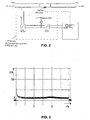
- Figure 3 shows a graph of Current (I) versus Time (s) relating to the sizing parameters above indicated.
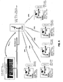
- FIG. 6 there is shown therein the controlling of five remote-controlled switches, each depending to an Electrical Traction Control System (DOTE) of a single station.
- DOTA Electrical Traction Control System
- the system foresees the use of a control device (for example, a control device as the ETG3021 Schneider) placed inside the housing of the switch, the control device being addressed for the management of the signals I/O, and for realizing the communication via a GPRS connection.
- a control device for example, a control device as the ETG3021 Schneider
- a PLC related to a substation will make all queries to all control devices (ETG3021) in order to obtain data acquisition and the management of all controls.
- the control device (ETG3021) is also designed to provide via a web-link the status of several connected switches.
- the apparatus and the system of the present invention has many advantages, both in terms of structural arrangement and management thereof.
- the present system allows a full availability of the control switches remotely, requires no special maintenance, and provides an operating range of -40 °C to +65 °C, equivalent to 10 years of useful life.
- system and the apparatus of the present invention is particularly advantageous for upgrading of existing networks (such as trolleys and streetcars in downtown/urban areas) wherein the laying of further cables for power supply circuits and remote control circuits it is not allowed, and wherein the making of said laying of cable lines would still be difficult to achieve.
- the apparatuses are powered by energy stored in high-capacity capacitors (Super Capacitors).
- the system and the apparatus of the present invention provides for quick installation and connecting time, in commissioning activities.
- the invention provides a wide communication range (distance) between apparatus and the place for the control panel.
Landscapes
- Engineering & Computer Science (AREA)
- Mechanical Engineering (AREA)
- Power Engineering (AREA)
- Transportation (AREA)
- Life Sciences & Earth Sciences (AREA)
- Sustainable Development (AREA)
- Sustainable Energy (AREA)
- Electric Propulsion And Braking For Vehicles (AREA)
- Monitoring And Testing Of Exchanges (AREA)
- Interface Circuits In Exchanges (AREA)
- Current-Collector Devices For Electrically Propelled Vehicles (AREA)
Description
- The present invention relates to a system for the power supplying and the remote controlling of electromechanical apparatuses of street railways lines, and more specifically to a system for the power supply and the remote control of electromechanical apparatuses of street railways lines wherein the use of supercapacitors it is provided.
- Up to now, the function of the different apparatuses in street railways lines is achieved through conventional wiring between operating units (e.g., switches) and auxiliary power supplies, such as electrical substations, UPS, or battery systems.
- In such systems, the necessary reserve of additional power, responsible for the operation of the different apparatuses, is guaranteed by means of batteries.
- This structural arrangement involves, however, some drawbacks.
- For example, the contacting line of a streetcar or a trolley bus is normally divided into electrically separate sections, each section being powered by a substation. In the case of out of service of a single sub-station, the contacting line has to be connected to the adjacent one by hand-operated switches. This manual operation may involve the inconvenience of long reconfiguration times.
- In addition, the mechanisms for controlling of switches and relevant remote controls must be fed individually, being not possible the connection thereof to a low voltage supply.
- Therefore, for the already existing installations for trolleybus and streetcars there is another drawback due to the fact that it is necessary to create ducts along the lines thereof for the laying of electric cables in order to supply power and remote controlling said switches.
- Moreover, there is further drawback in that in the case of upgrading existing networks such as buses and trolleys lines in downtown/urban areas, the latter normally are not liable to incorporate ducts for the laying of cables for the remote power, therefore the laying of said cables lines would still be difficult to achieve.
- On the other hand, in the art it is already known
DE 36 27 971 A1 (LICENTIA GmbH) published on 25 February 1988, which discloses an arrangement for controlling catenary disconnecting switches, whereby the arrangement provides respective driving line disconnectors, each disconnector being connected via a linkage to a drive motor, and being connected via at least two lines to a control part, and further comprising securing elements for the drive motor, at least one switch for applying power to the drive motor, and manually operable elements for the control of said switch, and elements for indicating the operating state of the contact line switch, further comprising fuse elements, and wherein each of the control parts of several drive motors comprises a remote control substation which is each connected to a central station. - It is also known from the state of the
art EP 1 552 998 A2 (ELETTROMECCANICA CM SRL) published on 13 July 2005, which discloses a system for the diagnosis and operation of apparatuses for generating and distributing power supplies, in particular for railway's safety and signalling plants, the system foresees a plurality of peripheral units provided with means for connecting to a power supply device, and means for detecting the efficiency of the controlled device and capable to feed a signal relating to any detected defect. - Further, it is also known from the state of the
art EP 1 550 575 A1 (ALSTOM) published on 6 July 2005, which discloses a system and station for the power supply to a catenary, and process of interruption of such power supply, which foresees three power supply stations to a catenary, and generators for transmitting control signals through the catenary. Each station has a receiver to receive the control signals transmitted via the catenary and to control interruption of the power supply of one portion of the catenary based on the control signals. Tehre is also disclosed a method of interruption of power supply of a portion of the failed catenary. - All of the above described systems have the drawback of not allowing the power supplying to low voltage auxiliary circuits in a autonomous manner, by deriving directly the power supply to said auxiliary services from the power supply of said contacting lines relevant to trolleybus, streetcars, and/or subways. Further, the above systems do not allow a remote control of both the power supply devices and the electromechanical apparatus related to the former, in an independent manner from the power supplies by means of wiring power systems and/or remote stations.
- The aim of the present invention is to solve the above drawbacks by providing a system and an apparatus for the power supplying and the remote controlling of electromechanical apparatuses in street railways lines and the like, the system allowing the power supplying to low voltage auxiliary circuits in a autonomous manner, by deriving directly the power supply to said auxiliary services from the power supply of said contacting lines relevant to trolleybus, streetcars, and/or metros themselves.
- Another object of the present invention is to provide an apparatus for the power supplying and the remote controlling of electromechanical apparatuses in street railways lines and the like, that provides a remote control of both the power supply device and the electromechanical apparatus related to it, and not depending on conventional power supplies by means of wiring power systems and/or remote stations.
- Thus, the present invention provides a system for the power supplying and the remote controlling of electromechanical apparatuses in street railways lines and the like substantially according to the appended claims.
- A detailed description of a preferred embodiment of a system for the power supplying and the remote controlling which comprises apparatuses for the remote power supplying and the remote controlling according to the present invention will now be given, given as an example and without limiting, by referring to the annexed drawings, wherein:
-
Figures 1A and 1B are schematic overall views a streetcar line which comprises the system and apparatuses of the present invention; -
Figure 2 is a schematic view of a circuit diagram of the system ofFigures 1A and 1B ; -
Figure 3 is a graph showing the current values over time, with reference to an actuator for a driven line switch; -
Figures 4 is a table showing the characteristic values of a supercapacitor included within the apparatus of the present invention; -
Figure 5 is a graph showing the electrical characteristics of the supercapacitor ofFigure 4 , and -
Figure 6 is a schematic view that shows the function of the system during the controlling of a plurality of apparatuses, according to the present invention. - It should be noted here that the following embodiment of the present invention refers to a power supplying and remote controlling for a streetcar line. Obviously, the present invention is not limited to this example.
- Referring now to
Figures 1A and 1B there is illustrated schematically the structural arrangement for the system according to the present invention, which incorporates one or more apparatuses for the remote controlling (the figures show only one of.them), and referred to a streetcar line. - As can be seen in the figures, the line is equipped with driven switches, the latter being remote controlled via remote drive of the streetcar.
- The operating mechanism of the switches and the remote control thereof is powered independently. According to the present invention, the power supply is provided by the contacting line, but through a 600/24 V DC converter.
- In the case of out of order of the contacting line, all the apparatuses are powered by energy which has been stored in high-capacity capacitors (SuperCapacitor) contained therein.
- With reference now to
Figure 2 , there is shown therein the circuit diagram of operating for the storage of power to be supplied to the apparatuses for the control of the driven switches and the remote control thereof, according to the present invention. - According to the arrangement of the present invention, during normal operation the voltage is taken from the contacting line and it is lowered to 28 V via a DC/DC converter, the latter provides for charging the batteries incorporating supercapacitors (see
Fig 1A andFig 2 ). - The apparatus is protected from incoming surges that might come from the line by means of a fuse incorporating switching signal and a Suppressor Varistor-Zinc Oxide.
- The power supply of all different apparatuses is 24 V, so the 28 V output is connected to a second converter/stabilizer that provides a constant voltage of 24 V during the capacitor discharging period.
- The capacity of the capacitor is sized to provide power to the remote control for 30 to 40 minutes, and for carrying out at least five operations of the switch itself.
- As can be understood in
Fig 1A andFig 2 , this power system is installed in a housing made of insulated material placed on the pole and alongside the junction housing where the power is to be derived from the 600V power supply. It is also necessary to make a physical link to the track in order to close the circuit on the negative. - The housing comprises the following devices:
- 1) Fuse breaker, fuse with a remote signal;
- 2) Suppressor Varistor-Zinc Oxide (for example, the type Z60M911 CKE);
- 3) Converter 600/28V (e.g., PSC-type series DC/DC 100-
150W 1 to 3 Outputs); - 4) Battery Supercapacitors (for example, the type BMOD BC Energy Series 15 V BOOSTCAP ® Ultracapacitors of Maxwell Technologies);
- 5) Converter / Stabilizer 100W-24/24V; and
- 6) Switch and terminals as necessary.
- With reference to
figure 1A and 1B , for what concerns the sizing of the switches, the invention provides that said switches be of the double interruption type; 1kVcc - 2kA, with a drive (driven by 24VDC motor), and the drive is connected to a properly insulated driving rod. - It is also possible to operate said switches locally on emergency, the operating being both electrically or manually.
- According to this embodiment, the electrical characteristics of the driving motor of the switch will be as follows:
DEVICES AND CONTROLS 24V DC (+10,-20 %) ELECTRIC MOTOR 24V DC (+10,-20 %) ANTICONDENSATION COIL 24V DC (+10,-15 %) EL. MOTOR - Start < 26,6 A EL. MOTOR - Function for 2,9 s < 5,2 A ANTICONDENSATION COIL < 0,85 A -
Figure 3 shows a graph of Current (I) versus Time (s) relating to the sizing parameters above indicated. - Referring now to
Figures 4 and 5 , there is shown therein the sizing parameters of the supercapacitor according to the embodiment of the present invention. - According to the electrical characteristics (power and energy) as above shown, it has been identified as an optimal solution the use of 4 banks of capacitors type BMOD0058E015, connected in series and in parallel with the electrical characteristics listed as in the table in
Figure 4 , and according to the charts ofFigure 5 . - With reference now to
Figure 6 and according to the present invention, it is provided that all switches are operated remotely in a group arrangement and by means of remote control. - For example, as shown in
Figure 6 , there is shown therein the controlling of five remote-controlled switches, each depending to an Electrical Traction Control System (DOTE) of a single station. The connection is made by plotting the signals of each switch directly to the acquiring node placed in referenced substation. - The network for the remote controlling of a plurality of substations is shown in the figure. For each switch will be controlled the following digital signals:
- 2 DI (relevant to the switch status)
- 2 DO (relevant to the control of the switches)
- 4 DI ( relevant to switch alarms and / or power system alarms).
- According to the present embodiment, the system foresees the use of a control device (for example, a control device as the ETG3021 Schneider) placed inside the housing of the switch, the control device being addressed for the management of the signals I/O, and for realizing the communication via a GPRS connection.
- According to the system of the present invention, there are provided similar devices in all substations, in order to communicate on the LAN and according to the schematic diagram shown in this
Figure 6 . - Further, a PLC related to a substation will make all queries to all control devices (ETG3021) in order to obtain data acquisition and the management of all controls.
- The control device (ETG3021) is also designed to provide via a web-link the status of several connected switches.
- The apparatus and the system of the present invention has many advantages, both in terms of structural arrangement and management thereof.
- The present system allows a full availability of the control switches remotely, requires no special maintenance, and provides an operating range of -40 °C to +65 °C, equivalent to 10 years of useful life.
- During the making of new installations for trolleybus and streetcars, unlike conventional systems, it is not longer necessary to create ducts along the line nor it is necessary to install cables for the power supplying and remote controlling of driven switches.
- Further, the system and the apparatus of the present invention is particularly advantageous for upgrading of existing networks (such as trolleys and streetcars in downtown/urban areas) wherein the laying of further cables for power supply circuits and remote control circuits it is not allowed, and wherein the making of said laying of cable lines would still be difficult to achieve.
- Thanks to the apparatus of the present invention it is possible to install driven loaded switches, instead of the standard manual switches.
- In the case of out of order of the contacting line, the apparatuses are powered by energy stored in high-capacity capacitors (Super Capacitors).
- The system and the apparatus of the present invention provides for quick installation and connecting time, in commissioning activities.
- Moreover, by providing supercapacitors instead of batteries related difficulties to the latter are avoided, such as a limited life and high maintenance costs.
- There is no cable laying and no relevant building construction included.
- The invention provides a wide communication range (distance) between apparatus and the place for the control panel.
Claims (10)
- A system for the remote controlling of a plurality of electromechanical apparatuses for the power supply to streetcars, trolleybus lines, and the like, the system being characterized in that
each electromechanical apparatus for the power supplying and the remote controlling comprises fuse and protection means; suppressor-varistor means; voltage conversion means; energy storing means, and converting/stabilizing means, wherein a plurality of driven line switches are provided, said plurality of switches being remote-controlled via remote control and controlled through said plurality electromechanical apparatuses,
and wherein- each electromechanical apparatus is associated to a respective remote controlling device,- said energy storing means are high-capacity supercapacitors, and- said plurality of switches and said plurality of electromechanical apparatuses for the power supplying and the remote controlling are remotely controlled in groups by means of a remote control and a wireless network for the remote management thereof. - System for the remote controlling of a plurality of electromechanical apparatuses for the power supply to streetcars, trolleybus lines, and the like, according to the preceding claim, wherein each remote controlling device communicates via GPRS or similar connection, wherein said wireless network further includes a LAN, wherein said wireless network further includes a sub-station PLC for the direct querying of different control devices, data acquisition, and management of said controls, and wherein the control devices provide the status of said switches via web connections.
- System for the remote controlling of a plurality of electromechanical apparatuses for the power supply to streetcars, trolleybus lines, and the like, according to the preceding claim, wherein said protection and fuse means comprises:- Fuse breaker, and- Remote signal Fuse.
- System for the remote controlling of a plurality of electromechanical apparatuses for the power supply to streetcars, trolleybus lines, and the like, according to the preceding claim, wherein said suppressor-varistor means comprises at least one zinc-oxide Suppressor- Varistor.
- System for the remote controlling of a plurality of electromechanical apparatuses for the power supply to streetcars, trolleybus lines, and the like, according to the preceding claim, wherein said voltage conversion means comprises a voltage converter 600/28V.
- System for the remote controlling of a plurality of electromechanical apparatuses for the power supply to streetcars, trolleybus lines, and the like, according to the preceding claim, wherein said converting/stabilizing means comprises at least one Converter/Stabilizer 100W-24/24V.
- System for the remote controlling of a plurality of electromechanical apparatuses for the power supply to streetcars, trolleybus lines, and the like, according to the preceding claim, wherein each electromechanical apparatus for the power supplying and remote controlling further comprises a housing made of insulated material.
- System for the remote controlling of a plurality of electromechanical apparatuses for the power supply to streetcars, trolleybus lines, and the like, according to the preceding claim, wherein the power supply to said plurality of electromechanical apparatuses is supplied from the contacting line through a 600/24 V DC converter.
- System for the remote controlling of a plurality of electromechanical apparatuses for the power supply to streetcars, trolleybus lines, and the like, according to the preceding claim, wherein said switches are double break switch type, 1kVcc - 2kA, with motorized driving and control through properly insulated rod.
- System for the remote controlling of a plurality of electromechanical apparatuses for the power supply to streetcars, trolleybus lines, and the like, according to the preceding claim, wherein said switches are operable either electrically or manually.
Applications Claiming Priority (2)
| Application Number | Priority Date | Filing Date | Title |
|---|---|---|---|
| ITRM2009A000501A IT1396053B1 (en) | 2009-10-01 | 2009-10-01 | SUPPLY EQUIPMENT AND REMOTE MONITORING ASUPERCONDENSATOR FOR ELETTROMECHANICAL EQUIPMENT FROM METROTRAMVIARY LINES |
| PCT/IB2010/002484 WO2011039621A2 (en) | 2009-10-01 | 2010-09-30 | A system for the remote controlling of electromechanical apparatuses in street railways lines, and the like |
Publications (2)
| Publication Number | Publication Date |
|---|---|
| EP2483101A2 EP2483101A2 (en) | 2012-08-08 |
| EP2483101B1 true EP2483101B1 (en) | 2014-06-18 |
Family
ID=42143554
Family Applications (1)
| Application Number | Title | Priority Date | Filing Date |
|---|---|---|---|
| EP10782369.2A Not-in-force EP2483101B1 (en) | 2009-10-01 | 2010-09-30 | A system for the remote controlling of electromechanical apparatuses in street railways lines, and the like |
Country Status (3)
| Country | Link |
|---|---|
| EP (1) | EP2483101B1 (en) |
| IT (1) | IT1396053B1 (en) |
| WO (1) | WO2011039621A2 (en) |
Families Citing this family (2)
| Publication number | Priority date | Publication date | Assignee | Title |
|---|---|---|---|---|
| CN103707779B (en) * | 2014-01-03 | 2015-12-02 | 山东鼎讯安控技术有限责任公司 | Coal mine roadway single file rail adaptive segmentation electric power system and method |
| CN104267703A (en) * | 2014-10-17 | 2015-01-07 | 成都四为电子信息股份有限公司 | Railway electromechanical device monitoring device |
Family Cites Families (8)
| Publication number | Priority date | Publication date | Assignee | Title |
|---|---|---|---|---|
| DE3627971A1 (en) * | 1986-08-18 | 1988-02-25 | Licentia Gmbh | Arrangement for controlling catenary disconnecting switches |
| FR2810278B1 (en) * | 2000-06-19 | 2002-10-11 | Renault Vehicules Ind | POWER SUPPLY SYSTEM FOR ELECTRICALLY DRIVEN VEHICLES |
| FR2825666B1 (en) * | 2001-06-06 | 2003-09-12 | Electricite De France | SYSTEM FOR DIRECT ELECTRICAL POWER SUPPLY OF A RAIL VEHICLE AND CORRESPONDING RAILWAY |
| CN1278885C (en) * | 2003-09-18 | 2006-10-11 | 上海交通大学 | Super capacitor tram charging control system |
| FR2864480B1 (en) * | 2003-12-31 | 2006-03-24 | Alstom | SYSTEM AND STATION FOR SUPPLYING A CATENARY, AND METHOD FOR INTERRUPTING THE SAME |
| ITFI20040007A1 (en) * | 2004-01-09 | 2004-04-09 | Elettromeccanica Cm S R L | SYSTEM FOR DIAGNOSTICS AND CONTROL OF POWER SUPPLY GENERATION AND DISTRIBUTION EQUIPMENT, IN PARTICULAR FOR RAILWAY SAFETY AND SIGNALING SYSTEMS |
| FR2871744B1 (en) * | 2004-06-21 | 2008-02-22 | Alstom Sa | ON-LINE POWER SUPPLY DEVICE ON A TRACTION VEHICLE, POWER SUPPLY METHOD, AND RECORDING MEDIUM OF THE METHOD |
| ATE526222T1 (en) * | 2007-10-25 | 2011-10-15 | Schweizer Electronic Ag | DEVICE AND METHOD FOR CONTROLLING AND/OR MONITORING A BARRIER SYSTEM |
-
2009
- 2009-10-01 IT ITRM2009A000501A patent/IT1396053B1/en active
-
2010
- 2010-09-30 EP EP10782369.2A patent/EP2483101B1/en not_active Not-in-force
- 2010-09-30 WO PCT/IB2010/002484 patent/WO2011039621A2/en not_active Ceased
Also Published As
| Publication number | Publication date |
|---|---|
| EP2483101A2 (en) | 2012-08-08 |
| WO2011039621A3 (en) | 2012-04-26 |
| WO2011039621A2 (en) | 2011-04-07 |
| ITRM20090501A1 (en) | 2011-04-02 |
| IT1396053B1 (en) | 2012-11-09 |
Similar Documents
| Publication | Publication Date | Title |
|---|---|---|
| US8729728B2 (en) | Power adjustment system adapted for powering an electric line for supplying power to vehicles | |
| EP2872359B1 (en) | Energy management system for railbound vehicles | |
| CN102424004A (en) | Motor train unit network side circuit and control method thereof | |
| US20210237611A1 (en) | Charging infrastructure unit, and charging infrastructure having a charging power option | |
| CN101459327B (en) | Automatic ice melting method for multiple division electricity transmission line and special switch thereof | |
| CN102481940A (en) | Aerial able car system having transportation operating equipment for passenger and/or freight transport | |
| US11285831B1 (en) | Matrix switches for optimizing resource utilization in large-scale charging stations with distributed energy resources | |
| KR20160030209A (en) | Electrical vehicle and associated transport facility | |
| EP3878680A2 (en) | Drive system for a railway vehicle | |
| WO2010026786A1 (en) | Power feed control system, and power feed control method | |
| CN108656955B (en) | Direct-current high-voltage box, double-system high-voltage traction system and electric motor train unit | |
| CN105449795A (en) | Tramcar ground charging power supply system and charging control method | |
| JP2013141374A (en) | Electric power supply system for electric railroad | |
| RU2596046C1 (en) | Alternate current traction substation for supply of traction loads 25 kv | |
| CN113572254B (en) | Train control system, train control management system and train | |
| EP2483101A2 (en) | A system for the remote controlling of electromechanical apparatuses in street railways lines, and the like | |
| JP2001320804A (en) | Power supply facility and electric car | |
| EP3476686B1 (en) | Cableway installation having transportation operating equipment for the transport of persons and/or freight | |
| CN202264649U (en) | Network side circuit of motor train unit | |
| CN208226663U (en) | A kind of over-zone feeding stacked switch cabinet device | |
| CN108859868B (en) | Method and system for vehicle-mounted automatic passing neutral section in-phase power supply mode | |
| CN201113546Y (en) | Vehicle mounted control electric network | |
| RU16226U1 (en) | AC TRACING SUBSTATION | |
| EP3682526B1 (en) | Method and apparatus for transmitting electric energy | |
| JPH10117401A (en) | Electric power supply system in electric railway |
Legal Events
| Date | Code | Title | Description |
|---|---|---|---|
| PUAI | Public reference made under article 153(3) epc to a published international application that has entered the european phase |
Free format text: ORIGINAL CODE: 0009012 |
|
| 17P | Request for examination filed |
Effective date: 20120427 |
|
| AK | Designated contracting states |
Kind code of ref document: A2 Designated state(s): AL AT BE BG CH CY CZ DE DK EE ES FI FR GB GR HR HU IE IS IT LI LT LU LV MC MK MT NL NO PL PT RO SE SI SK SM TR |
|
| DAX | Request for extension of the european patent (deleted) | ||
| GRAP | Despatch of communication of intention to grant a patent |
Free format text: ORIGINAL CODE: EPIDOSNIGR1 |
|
| INTG | Intention to grant announced |
Effective date: 20131211 |
|
| GRAS | Grant fee paid |
Free format text: ORIGINAL CODE: EPIDOSNIGR3 |
|
| GRAA | (expected) grant |
Free format text: ORIGINAL CODE: 0009210 |
|
| AK | Designated contracting states |
Kind code of ref document: B1 Designated state(s): AL AT BE BG CH CY CZ DE DK EE ES FI FR GB GR HR HU IE IS IT LI LT LU LV MC MK MT NL NO PL PT RO SE SI SK SM TR |
|
| REG | Reference to a national code |
Ref country code: GB Ref legal event code: FG4D |
|
| REG | Reference to a national code |
Ref country code: CH Ref legal event code: EP |
|
| REG | Reference to a national code |
Ref country code: AT Ref legal event code: REF Ref document number: 673131 Country of ref document: AT Kind code of ref document: T Effective date: 20140715 |
|
| REG | Reference to a national code |
Ref country code: IE Ref legal event code: FG4D |
|
| REG | Reference to a national code |
Ref country code: DE Ref legal event code: R096 Ref document number: 602010016850 Country of ref document: DE Effective date: 20140731 |
|
| PG25 | Lapsed in a contracting state [announced via postgrant information from national office to epo] |
Ref country code: NO Free format text: LAPSE BECAUSE OF FAILURE TO SUBMIT A TRANSLATION OF THE DESCRIPTION OR TO PAY THE FEE WITHIN THE PRESCRIBED TIME-LIMIT Effective date: 20140918 Ref country code: FI Free format text: LAPSE BECAUSE OF FAILURE TO SUBMIT A TRANSLATION OF THE DESCRIPTION OR TO PAY THE FEE WITHIN THE PRESCRIBED TIME-LIMIT Effective date: 20140618 Ref country code: CY Free format text: LAPSE BECAUSE OF FAILURE TO SUBMIT A TRANSLATION OF THE DESCRIPTION OR TO PAY THE FEE WITHIN THE PRESCRIBED TIME-LIMIT Effective date: 20140618 Ref country code: GR Free format text: LAPSE BECAUSE OF FAILURE TO SUBMIT A TRANSLATION OF THE DESCRIPTION OR TO PAY THE FEE WITHIN THE PRESCRIBED TIME-LIMIT Effective date: 20140919 Ref country code: LT Free format text: LAPSE BECAUSE OF FAILURE TO SUBMIT A TRANSLATION OF THE DESCRIPTION OR TO PAY THE FEE WITHIN THE PRESCRIBED TIME-LIMIT Effective date: 20140618 |
|
| REG | Reference to a national code |
Ref country code: NL Ref legal event code: VDEP Effective date: 20140618 |
|
| REG | Reference to a national code |
Ref country code: AT Ref legal event code: MK05 Ref document number: 673131 Country of ref document: AT Kind code of ref document: T Effective date: 20140618 |
|
| REG | Reference to a national code |
Ref country code: LT Ref legal event code: MG4D |
|
| PG25 | Lapsed in a contracting state [announced via postgrant information from national office to epo] |
Ref country code: SE Free format text: LAPSE BECAUSE OF FAILURE TO SUBMIT A TRANSLATION OF THE DESCRIPTION OR TO PAY THE FEE WITHIN THE PRESCRIBED TIME-LIMIT Effective date: 20140618 Ref country code: LV Free format text: LAPSE BECAUSE OF FAILURE TO SUBMIT A TRANSLATION OF THE DESCRIPTION OR TO PAY THE FEE WITHIN THE PRESCRIBED TIME-LIMIT Effective date: 20140618 Ref country code: HR Free format text: LAPSE BECAUSE OF FAILURE TO SUBMIT A TRANSLATION OF THE DESCRIPTION OR TO PAY THE FEE WITHIN THE PRESCRIBED TIME-LIMIT Effective date: 20140618 |
|
| PG25 | Lapsed in a contracting state [announced via postgrant information from national office to epo] |
Ref country code: CZ Free format text: LAPSE BECAUSE OF FAILURE TO SUBMIT A TRANSLATION OF THE DESCRIPTION OR TO PAY THE FEE WITHIN THE PRESCRIBED TIME-LIMIT Effective date: 20140618 Ref country code: EE Free format text: LAPSE BECAUSE OF FAILURE TO SUBMIT A TRANSLATION OF THE DESCRIPTION OR TO PAY THE FEE WITHIN THE PRESCRIBED TIME-LIMIT Effective date: 20140618 Ref country code: SK Free format text: LAPSE BECAUSE OF FAILURE TO SUBMIT A TRANSLATION OF THE DESCRIPTION OR TO PAY THE FEE WITHIN THE PRESCRIBED TIME-LIMIT Effective date: 20140618 Ref country code: ES Free format text: LAPSE BECAUSE OF FAILURE TO SUBMIT A TRANSLATION OF THE DESCRIPTION OR TO PAY THE FEE WITHIN THE PRESCRIBED TIME-LIMIT Effective date: 20140618 Ref country code: RO Free format text: LAPSE BECAUSE OF FAILURE TO SUBMIT A TRANSLATION OF THE DESCRIPTION OR TO PAY THE FEE WITHIN THE PRESCRIBED TIME-LIMIT Effective date: 20140618 Ref country code: PT Free format text: LAPSE BECAUSE OF FAILURE TO SUBMIT A TRANSLATION OF THE DESCRIPTION OR TO PAY THE FEE WITHIN THE PRESCRIBED TIME-LIMIT Effective date: 20141020 |
|
| PG25 | Lapsed in a contracting state [announced via postgrant information from national office to epo] |
Ref country code: NL Free format text: LAPSE BECAUSE OF FAILURE TO SUBMIT A TRANSLATION OF THE DESCRIPTION OR TO PAY THE FEE WITHIN THE PRESCRIBED TIME-LIMIT Effective date: 20140618 Ref country code: PL Free format text: LAPSE BECAUSE OF FAILURE TO SUBMIT A TRANSLATION OF THE DESCRIPTION OR TO PAY THE FEE WITHIN THE PRESCRIBED TIME-LIMIT Effective date: 20140618 Ref country code: AT Free format text: LAPSE BECAUSE OF FAILURE TO SUBMIT A TRANSLATION OF THE DESCRIPTION OR TO PAY THE FEE WITHIN THE PRESCRIBED TIME-LIMIT Effective date: 20140618 Ref country code: IS Free format text: LAPSE BECAUSE OF FAILURE TO SUBMIT A TRANSLATION OF THE DESCRIPTION OR TO PAY THE FEE WITHIN THE PRESCRIBED TIME-LIMIT Effective date: 20141018 |
|
| REG | Reference to a national code |
Ref country code: DE Ref legal event code: R097 Ref document number: 602010016850 Country of ref document: DE |
|
| REG | Reference to a national code |
Ref country code: DE Ref legal event code: R119 Ref document number: 602010016850 Country of ref document: DE |
|
| PLBE | No opposition filed within time limit |
Free format text: ORIGINAL CODE: 0009261 |
|
| STAA | Information on the status of an ep patent application or granted ep patent |
Free format text: STATUS: NO OPPOSITION FILED WITHIN TIME LIMIT |
|
| PG25 | Lapsed in a contracting state [announced via postgrant information from national office to epo] |
Ref country code: LU Free format text: LAPSE BECAUSE OF FAILURE TO SUBMIT A TRANSLATION OF THE DESCRIPTION OR TO PAY THE FEE WITHIN THE PRESCRIBED TIME-LIMIT Effective date: 20140930 Ref country code: DK Free format text: LAPSE BECAUSE OF FAILURE TO SUBMIT A TRANSLATION OF THE DESCRIPTION OR TO PAY THE FEE WITHIN THE PRESCRIBED TIME-LIMIT Effective date: 20140618 Ref country code: MC Free format text: LAPSE BECAUSE OF FAILURE TO SUBMIT A TRANSLATION OF THE DESCRIPTION OR TO PAY THE FEE WITHIN THE PRESCRIBED TIME-LIMIT Effective date: 20140618 |
|
| REG | Reference to a national code |
Ref country code: CH Ref legal event code: PL |
|
| 26N | No opposition filed |
Effective date: 20150319 |
|
| GBPC | Gb: european patent ceased through non-payment of renewal fee |
Effective date: 20140930 |
|
| REG | Reference to a national code |
Ref country code: DE Ref legal event code: R119 Ref document number: 602010016850 Country of ref document: DE Effective date: 20150401 |
|
| REG | Reference to a national code |
Ref country code: FR Ref legal event code: ST Effective date: 20150529 |
|
| REG | Reference to a national code |
Ref country code: IE Ref legal event code: MM4A |
|
| REG | Reference to a national code |
Ref country code: DE Ref legal event code: R097 Ref document number: 602010016850 Country of ref document: DE Effective date: 20150319 |
|
| PG25 | Lapsed in a contracting state [announced via postgrant information from national office to epo] |
Ref country code: CH Free format text: LAPSE BECAUSE OF NON-PAYMENT OF DUE FEES Effective date: 20140930 Ref country code: SI Free format text: LAPSE BECAUSE OF FAILURE TO SUBMIT A TRANSLATION OF THE DESCRIPTION OR TO PAY THE FEE WITHIN THE PRESCRIBED TIME-LIMIT Effective date: 20140618 Ref country code: DE Free format text: LAPSE BECAUSE OF NON-PAYMENT OF DUE FEES Effective date: 20150401 Ref country code: LI Free format text: LAPSE BECAUSE OF NON-PAYMENT OF DUE FEES Effective date: 20140930 Ref country code: GB Free format text: LAPSE BECAUSE OF NON-PAYMENT OF DUE FEES Effective date: 20140930 |
|
| PG25 | Lapsed in a contracting state [announced via postgrant information from national office to epo] |
Ref country code: IE Free format text: LAPSE BECAUSE OF NON-PAYMENT OF DUE FEES Effective date: 20140930 Ref country code: FR Free format text: LAPSE BECAUSE OF NON-PAYMENT OF DUE FEES Effective date: 20140930 Ref country code: IT Free format text: LAPSE BECAUSE OF NON-PAYMENT OF DUE FEES Effective date: 20140930 |
|
| PG25 | Lapsed in a contracting state [announced via postgrant information from national office to epo] |
Ref country code: SM Free format text: LAPSE BECAUSE OF FAILURE TO SUBMIT A TRANSLATION OF THE DESCRIPTION OR TO PAY THE FEE WITHIN THE PRESCRIBED TIME-LIMIT Effective date: 20140618 |
|
| PG25 | Lapsed in a contracting state [announced via postgrant information from national office to epo] |
Ref country code: MT Free format text: LAPSE BECAUSE OF FAILURE TO SUBMIT A TRANSLATION OF THE DESCRIPTION OR TO PAY THE FEE WITHIN THE PRESCRIBED TIME-LIMIT Effective date: 20140618 Ref country code: BG Free format text: LAPSE BECAUSE OF FAILURE TO SUBMIT A TRANSLATION OF THE DESCRIPTION OR TO PAY THE FEE WITHIN THE PRESCRIBED TIME-LIMIT Effective date: 20140618 |
|
| PG25 | Lapsed in a contracting state [announced via postgrant information from national office to epo] |
Ref country code: TR Free format text: LAPSE BECAUSE OF FAILURE TO SUBMIT A TRANSLATION OF THE DESCRIPTION OR TO PAY THE FEE WITHIN THE PRESCRIBED TIME-LIMIT Effective date: 20140618 Ref country code: HU Free format text: LAPSE BECAUSE OF FAILURE TO SUBMIT A TRANSLATION OF THE DESCRIPTION OR TO PAY THE FEE WITHIN THE PRESCRIBED TIME-LIMIT; INVALID AB INITIO Effective date: 20100930 Ref country code: BE Free format text: LAPSE BECAUSE OF FAILURE TO SUBMIT A TRANSLATION OF THE DESCRIPTION OR TO PAY THE FEE WITHIN THE PRESCRIBED TIME-LIMIT Effective date: 20140618 |
|
| PG25 | Lapsed in a contracting state [announced via postgrant information from national office to epo] |
Ref country code: MK Free format text: LAPSE BECAUSE OF FAILURE TO SUBMIT A TRANSLATION OF THE DESCRIPTION OR TO PAY THE FEE WITHIN THE PRESCRIBED TIME-LIMIT Effective date: 20140618 |
|
| PG25 | Lapsed in a contracting state [announced via postgrant information from national office to epo] |
Ref country code: AL Free format text: LAPSE BECAUSE OF FAILURE TO SUBMIT A TRANSLATION OF THE DESCRIPTION OR TO PAY THE FEE WITHIN THE PRESCRIBED TIME-LIMIT Effective date: 20140618 |