EP2483046B1 - Arrangement of a counter reflector device for use in heating an object, installation and method of heating - Google Patents
Arrangement of a counter reflector device for use in heating an object, installation and method of heating Download PDFInfo
- Publication number
- EP2483046B1 EP2483046B1 EP10760089.2A EP10760089A EP2483046B1 EP 2483046 B1 EP2483046 B1 EP 2483046B1 EP 10760089 A EP10760089 A EP 10760089A EP 2483046 B1 EP2483046 B1 EP 2483046B1
- Authority
- EP
- European Patent Office
- Prior art keywords
- reflective
- heating
- reflector
- shield portions
- reflective device
- Prior art date
- Legal status (The legal status is an assumption and is not a legal conclusion. Google has not performed a legal analysis and makes no representation as to the accuracy of the status listed.)
- Active
Links
Images

Classifications
-
- B—PERFORMING OPERATIONS; TRANSPORTING
- B29—WORKING OF PLASTICS; WORKING OF SUBSTANCES IN A PLASTIC STATE IN GENERAL
- B29B—PREPARATION OR PRETREATMENT OF THE MATERIAL TO BE SHAPED; MAKING GRANULES OR PREFORMS; RECOVERY OF PLASTICS OR OTHER CONSTITUENTS OF WASTE MATERIAL CONTAINING PLASTICS
- B29B13/00—Conditioning or physical treatment of the material to be shaped
- B29B13/02—Conditioning or physical treatment of the material to be shaped by heating
- B29B13/023—Half-products, e.g. films, plates
- B29B13/024—Hollow bodies, e.g. tubes or profiles
-
- B—PERFORMING OPERATIONS; TRANSPORTING
- B29—WORKING OF PLASTICS; WORKING OF SUBSTANCES IN A PLASTIC STATE IN GENERAL
- B29C—SHAPING OR JOINING OF PLASTICS; SHAPING OF MATERIAL IN A PLASTIC STATE, NOT OTHERWISE PROVIDED FOR; AFTER-TREATMENT OF THE SHAPED PRODUCTS, e.g. REPAIRING
- B29C49/00—Blow-moulding, i.e. blowing a preform or parison to a desired shape within a mould; Apparatus therefor
- B29C49/42—Component parts, details or accessories; Auxiliary operations
- B29C49/64—Heating or cooling preforms, parisons or blown articles
- B29C49/68—Ovens specially adapted for heating preforms or parisons
- B29C49/6835—Ovens specially adapted for heating preforms or parisons using reflectors
-
- B—PERFORMING OPERATIONS; TRANSPORTING
- B29—WORKING OF PLASTICS; WORKING OF SUBSTANCES IN A PLASTIC STATE IN GENERAL
- B29C—SHAPING OR JOINING OF PLASTICS; SHAPING OF MATERIAL IN A PLASTIC STATE, NOT OTHERWISE PROVIDED FOR; AFTER-TREATMENT OF THE SHAPED PRODUCTS, e.g. REPAIRING
- B29C49/00—Blow-moulding, i.e. blowing a preform or parison to a desired shape within a mould; Apparatus therefor
- B29C49/42—Component parts, details or accessories; Auxiliary operations
- B29C49/64—Heating or cooling preforms, parisons or blown articles
- B29C49/6409—Thermal conditioning of preforms
- B29C49/6436—Thermal conditioning of preforms characterised by temperature differential
- B29C49/6445—Thermal conditioning of preforms characterised by temperature differential through the preform length
-
- H—ELECTRICITY
- H05—ELECTRIC TECHNIQUES NOT OTHERWISE PROVIDED FOR
- H05B—ELECTRIC HEATING; ELECTRIC LIGHT SOURCES NOT OTHERWISE PROVIDED FOR; CIRCUIT ARRANGEMENTS FOR ELECTRIC LIGHT SOURCES, IN GENERAL
- H05B3/00—Ohmic-resistance heating
- H05B3/0033—Heating devices using lamps
- H05B3/0038—Heating devices using lamps for industrial applications
- H05B3/0057—Heating devices using lamps for industrial applications for plastic handling and treatment
-
- B—PERFORMING OPERATIONS; TRANSPORTING
- B29—WORKING OF PLASTICS; WORKING OF SUBSTANCES IN A PLASTIC STATE IN GENERAL
- B29C—SHAPING OR JOINING OF PLASTICS; SHAPING OF MATERIAL IN A PLASTIC STATE, NOT OTHERWISE PROVIDED FOR; AFTER-TREATMENT OF THE SHAPED PRODUCTS, e.g. REPAIRING
- B29C35/00—Heating, cooling or curing, e.g. crosslinking or vulcanising; Apparatus therefor
- B29C35/02—Heating or curing, e.g. crosslinking or vulcanizing during moulding, e.g. in a mould
- B29C35/08—Heating or curing, e.g. crosslinking or vulcanizing during moulding, e.g. in a mould by wave energy or particle radiation
- B29C35/0805—Heating or curing, e.g. crosslinking or vulcanizing during moulding, e.g. in a mould by wave energy or particle radiation using electromagnetic radiation
- B29C2035/0822—Heating or curing, e.g. crosslinking or vulcanizing during moulding, e.g. in a mould by wave energy or particle radiation using electromagnetic radiation using IR radiation
-
- B—PERFORMING OPERATIONS; TRANSPORTING
- B29—WORKING OF PLASTICS; WORKING OF SUBSTANCES IN A PLASTIC STATE IN GENERAL
- B29C—SHAPING OR JOINING OF PLASTICS; SHAPING OF MATERIAL IN A PLASTIC STATE, NOT OTHERWISE PROVIDED FOR; AFTER-TREATMENT OF THE SHAPED PRODUCTS, e.g. REPAIRING
- B29C49/00—Blow-moulding, i.e. blowing a preform or parison to a desired shape within a mould; Apparatus therefor
- B29C49/42—Component parts, details or accessories; Auxiliary operations
- B29C49/64—Heating or cooling preforms, parisons or blown articles
- B29C49/6409—Thermal conditioning of preforms
- B29C49/6418—Heating of preforms
-
- B—PERFORMING OPERATIONS; TRANSPORTING
- B29—WORKING OF PLASTICS; WORKING OF SUBSTANCES IN A PLASTIC STATE IN GENERAL
- B29C—SHAPING OR JOINING OF PLASTICS; SHAPING OF MATERIAL IN A PLASTIC STATE, NOT OTHERWISE PROVIDED FOR; AFTER-TREATMENT OF THE SHAPED PRODUCTS, e.g. REPAIRING
- B29C49/00—Blow-moulding, i.e. blowing a preform or parison to a desired shape within a mould; Apparatus therefor
- B29C49/42—Component parts, details or accessories; Auxiliary operations
- B29C49/64—Heating or cooling preforms, parisons or blown articles
- B29C49/68—Ovens specially adapted for heating preforms or parisons
- B29C49/685—Rotating the preform in relation to heating means
Definitions
- the present invention relates generally to the heating of objects. It relates more particularly to a heating installation comprising a plurality of heating elements adapted to produce heating of objects that typically move along a path, for instance heating of thermoplastic objects such as plastic preforms.
- the invention also relates to a counter reflector device for use in heating a moving object, and a method of heating an object with the aid of such a counter reflector device.
- thermoplastic preform intended for the manufacture of a container
- Ovens for blowing plastic preforms to make plastic bottles often are provided with IR lamps, a back-reflector at the rear of the lamps, and a counter reflector arranged opposite the radiation sources.
- the preform is heated on the move, its neck facing downward or upward.
- Each preform is rotated about itself, around a vertical axis, so that the lamps radiate to the whole periphery of the preform body.
- the height of the heating lamp assembly is chosen in relation to the length of the body of the preform.
- the preforms are moving along a path defined between two respective lateral walls of the oven, one of which is provided with the lamps and the back-reflector, the other one being provided with the counter reflector.
- WO 2006/002751 A1 discloses such a counter reflector according to the preambles of claims 1 and 9, which is profiled on the surface thereof facing the preform.
- the IR beams are directed back onto the preform with such a configuration.
- losses in the oven are reduced and an appreciable concomitant reduction in the consumption of electrical energy is obtained.
- thermoplastic container manufacturers still seek to reduce as far as possible the inherent charges associated with the operation of the machines for manufacturing these containers, and especially the consumption of electrical energy by these machines.
- the object of the invention is therefore to meet this expectation of users and to provide means suitable for optimizing the efficiency in the heating installation.
- Embodiments of the present invention provide a heating installation according to claim 1.
- some parts of the objects to be heated can be protected from the unwanted IR irradiation (e.g. those providing from the main reflective portion).
- some parts of the object and/or driving means for moving the object may advantageously be protected from radiation of the lamps, in particular radiation of the lamps that are the most distant from the level of the proximal reflective surface. Losses due to lost radiation are also minimized.
- the heating installation may be provided with a first shield portion defining with the said plane an angle in the range between 45 and 90°.
- the second shield portion may be integral with the secondary reflective device or correspond to an optional element that can be removed from the secondary reflective device.
- a IR cut-off shield is obtained with a high capacity to reflect radiation from the most distant lamps.
- the free end of such a cut-off shield may also be very close to the object (for instance about 1 cm) to increase the cut-off effect.
- the part of IR radiation that is reflected by the reflective element is focused on the determined portion of the object.
- the heat profile on this determined option of the object is different from the thermal profile of the other parts of the object. Additionally, this thermal profile can be tailored by providing an adapted optical design of the reflective element. This heating of this determined portion is accordingly very well controlled while not disturbing the heating of the other parts of the object. This technique is especially useful if one wishes to heat a part of the object differently from the other parts of the object, e.g. a neck of the preform of a PET bottle if said object is such a preform.
- the heat flux from the lamps is concentrated over a specific part of the preform height, corresponding to the level of the proximal reflecting surface.
- the shield portions by preventing heating outside the concentration area, avoid the use of additional cooling system for the determined portion of the object.
- the secondary reflective device is arranged so that the position of the reflective element with respect to the main reflective portion can be changed, tuned, adapted or adjusted.
- the reflective element may be displaced along the object height in order to heat another specific region.
- one or few other reflective elements with similar or different shapes and properties may be added along the object height.
- a plurality of reflective elements e.g. having the same shape and configuration
- the reflective surface of the main reflective portion is flat, or comprises cavities to reorient the reflected IR radiation as disclosed for example in WO 2006/002751 .
- One object of the present invention is also to provide a counter reflective device suitable for increasing heating efficiency.
- One object of the present invention is also to provide a method adapted for heating objects typically moving along a defined path.
- the method comprises heating more in the first operating area than in a second operating area extending between the second reflector and a second section of the first lateral wall provided with at least one of the heating elements, by disposing a reflective surface of the second reflector, arranged between said transverse shield portions, at a proximal location relative to said object.
- the object to be heated being a thermoplastic preform intended for the manufacture of a container after a forming of the heated object, the method further comprises:
- FIG. 1 A heating installation 10 in accordance with a first embodiment of the invention is depicted in Figs 1-2 .
- the installation may be all or part of an oven.
- the oven is arranged with a gap 11 between the two lateral walls 12, 13.
- a first wall 12 of the lateral walls is provided with heating elements 14, here lamps or similar radiating sources each having a tubular outer bulb 14a. IR halogen lamps may be used.
- preforms 15 are moved along a path crossing said gap 11.
- the preforms 15 are here placed with their necks 15a down.
- any other heat-sensitive objects may be treated through the installation 10.
- the heating installation 10 may be used for any pre-heating application, any heat processing for plastics, heat shrinkage of packaging and may also be used as ovens for semi-conductor, paper applications.
- the heating installation 10 is adapted for use in an oven of a blow molding machine for heating plastic preforms 15 prior to blow molding.
- the lateral walls 12, 13 of the heating installation 10 are elongated and are facing each other a certain distance apart. Preforms 15 thus can be heated when moving within the gap 11, along a defined path.
- Each preform 15 is moved longitudinally between the lateral walls 12, 13, typically with a rotation around its axis YY. The preform 15 is subjected to a predetermined heating profile in a short time.
- the gap 11 may be partly or entirely be closed, beyond the closed end 15b of the preform 15 on the path and near said closed end 15b, here above the closed end 15b, so that at least some of the radiation emitted beyond the closed end 15b of the preform 15 is reflected toward the body 15c of the preform 15. Thereby, the losses due to lost radiation are limited.
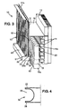
- a transverse plate 16 (only shown in Fig. 3 ) may be removably mounted on one of the lateral walls 12, 13 of the oven for this purpose. A passage for ventilation, preventing the oven from overheating, may be also provided. In Fig. 3 , the transverse plate 16 is attached to the first lateral wall 12.
- the first wall 12 is provided with the heating elements 14 to irradiate the preform 15 from a reflecting face.
- This reflecting face extends along the path, with a length significantly higher (for instance at least four times higher) than an average diameter or similar characteristic dimension of the transversal section in the objects to be heated, here the horizontal section of the plastic preforms 15.
- the first lateral wall 12 is provided with a main reflector 20 that extends between the transverse plate 16 and an opposite level corresponding to the neck 15a of the preform 15.
- Such a main reflector 20 is located adjacent said heating elements 14 and is also called a back-reflector.
- the second lateral wall 13 comprises a first reflector 31, facing at least one part of the preform body 15c and the closed end 15b, and a second reflector 32 facing another part, adjacent the neck 15a, of the preform body 15c.
- the first reflector 31 extends between a first elongated end 31a and a second elongated end 31b. These first and second ends 31 a, 31b follow the longitudinal direction of the path.
- the second reflector 32 is physically secured, directly or indirectly, to the first reflector 31 at said first end 31 a.
- the second reflector 32 is directly secured to the first reflector 31 to form an extension.
- the second reflector 32 may be displaceable with respect to the first reflector 31 and fixed with an adjustable position.
- the second reflector 32 comprises a first elongated transverse shield portion 33 and a second elongated transverse shield portion 34. An elongated cavity 35 is defined between these first and second transverse shield portions 33, 34.
- the spacing between the transverse shield portions 33, 34 may be adjusted according to a portion of the preform height that need a more concentrated heating.
- at least the second transverse shield portions 34 may be separable from the rest of the second reflector 32. It is here understood that these transverse shield portions 33, 34 are significantly different and greater than the optional raised areas which could provided in the counter reflector, for instance in the first reflector 31.
- the first reflector 31 is disposed far from the heating elements 14, behind the preform 15. This disposition reduces the complexity of the thermal management close to the heating elements 14. It also permits a better protection of the part of the preform 15 that is distant from the neck 15a.
- the second reflector32 is arranged with a U profile and a shorter height, in front of some of the heating elements 14 and behind the preform wall, closer as possible from the preform 15.
- reflection of the corresponding radiation is increased at the level of the second reflector 32, which is provided with a proximal reflecting surface.
- the front face defined by the first reflector 31 and the second reflector 32 advantageously comprises said proximal reflecting surface, which is defined by the surface 350 of said cavity 35, and a distal reflective surface, defined by the first reflector 31.
- the junction portion(s) of the second reflector 32 that joint said proximal reflecting surface to the distal reflective surface defined by the first reflector 31 is here provided at the level of the first end 31a.
- a planar section 40 at the top of the second reflector 32, perpendicular to at least one the two lateral walls 12, 13, is in contact with the first end 31a of the first reflector 31.
- this planar section 40 is the junction portion and the first elongated transverse shield portion 33 corresponds to the proximal end of this planar section 40.
- another planar section 42 may be provided at the lower side of the second reflector 32, which is arranged in parallel relative to the planar section 40.
- the second reflector 32 is arranged with the two transverse shield portions 33, 34 protruding from the rest of the second reflector 32. It can be seen in the non-limitative exemplary embodiments of Fig. 1-3 that the cavity 35 is arranged in a region closer to the preform wall than the distal surface, which is here flat, of the second reflector 32.
- the distal surface of the first reflector 31 may be profiled, for instance, with a plurality of identical cavities.
- the proximal reflecting surface extends in a position adjacent to a determined portion of a preform body 15c, here the shoulder region, which extends from the neck 15a, while the distal reflective surface is facing another portion of the preform body 15c, which is complementary to said determined portion.
- the two transverse shield portions 33, 34 protrude transversally with respect to a plane defined by a major portion the front face.
- the front face extends vertically, parallel to the central axis YY around which the preform 15 extends and may be rotated.
- the surface 350 of the cavity 35 is U-shaped in cross section or may be arranged in a general concave shape, for example a parabolic or semi circular shape, a W shape or the like.
- the depth Dc of the cavity 35 is preferably inferior to the distance Dt between the free edge 33a a of the first transverse shield portion 33 and the first reflector 31.
- the proximal surface delimits an interior volume entirely shifted relative to the first end 31a of the first reflector 31.
- a virtual plane secant with the first end 31 a and the second end 31b of the first reflector 31 does not intersect this interior volume. Accordingly, only the interior volume of the cavity 35 has a closer position relative to the path to concentrate the heating on the adjacent preform wall.
- the radiation from the uppermost heating elements 14 is reflected by the respective top surfaces of the transverse shield portions 33, 34, in order to protect the neck 15a or similar end of the object to be heated. Heating of the neck 15a and of any driven means that cooperate with the neck 15a is thus prevented.
- the transverse shield portion 34 of the second reflector 32 extends very close to the preform 15, at the junction between the body 15c and the neck 15a.
- the transverse shield portions 33, 34 function here as reflecting cutoff shields, adapted to protect the corresponding intermediary portion of the preform 15 to be further heated by reflected radiation of the most distant lamps 16.
- the reflecting top surface of the transverse shield portion 34 may be a planar surface.
- the transverse shield portion 34 extends at the level of the central axis of the lower heating element 14, which is partly arranged at a lower level than the body 15c.
- the lower heating element 14 is thus, partly, at a lower level than the proximal reflective surface and the main direction, here inclined, of the radiant output of this heating element 14 is secant with the proximal reflective surface.
- Fig. 1 shows reflection of a beam emitted from one of the upper heating elements 14.
- the top surface, which is here planar, of the first transverse shield portion 33 reflects this beam upward, toward the first reflector 31. This prevents heating of the neck 15a as above indicated and this reflected radiation may advantageously be used for heating of the closed end 15b. As a result, efficiency of the heating process in increased.
- a suitable material for the counter reflector defined by the first and second reflectors 31, 32 is a ceramic material or similar heat conductor material, for example material in alumina or such material having high reflectivity (>90%) and high conductivity (>20W/mK).
- the proximal reflecting surface and the distal reflecting surface may each comprise a material with a melting temperature higher than 600°C.
- the respective first and second reflectors 31, 32 may be integrally made of ceramic material. In the embodiment shown in Fig. 4 , only the surface that is close may be coated with such a material. Ceramic material or other similar heat-conductor material may be used for this purpose.
- the counter reflector with the two different reflectors 31, 32 may be optionally used in an oven of a blow molding machine for heating plastic preforms 15 that are each moved according to a general direction along the transport path.
- the preforms 15 are preferably rotated around their axis YY, using a mandrel (not shown). Such a mandrel may be longitudinally driven between the two lateral walls 12, 13 and typically cooperates with the neck 15a of the preform 15 by engaging elements.
- These preforms 15 are intended for the manufacture of containers such as plastic bottles to be filled with a liquid.
- the method for heating these preforms 15 is performed, here simultaneously with a longitudinal movement of the preforms 15 along the transport path, by heating the preforms 15 (on a predetermined preform height) by the heating elements 14 arranged one above the other according to a general stacking direction, and reflecting the radiation of the heating elements 14 by a counter reflector defined by the first reflector 31 and the second reflector 32.
- this method comprises:
- the radiation may be optically concentrated over a specific area, typically a small area, through use of a proximal reflection with the second reflector 32. While the temperature increases in the first operating area 51, here a lower area, such an increase may be controlled with the configuration of the second reflector 32 since impact of the upper heating elements 14 is limited relative to the first operating area 51. As a result, in comparison with a conventional construction of an oven, for a same heating operation, power of one or several radiating lamps or similar heating elements 14 may be reduced and/or the total number of the heating elements 14 may be reduced.
- the present invention has been described in connection with the preferred embodiments. These embodiments, however, are merely for example and the invention is not restricted thereto. It will be understood by those skilled in the art that other variations and modifications can easily be made within the scope of the invention as defined by the appended claims, thus it is only intended that the present invention be limited by the following claims.
- the invention may be implemented in any machine intended to heat an object, with any possible elongated form for the heating elements 14.
- the word "elongated” should not be interpreted in a restrictive manner and the length of the respective lateral walls 12, 13 may just be equal or slightly superior to the perimeter or similar dimension of the objects to be heated.
- the transport path may also be curved and the lateral walls 12, 13 curved in a corresponding manner and/or decomposed in a plurality of successive walls.
Landscapes
- Physics & Mathematics (AREA)
- Thermal Sciences (AREA)
- Engineering & Computer Science (AREA)
- Mechanical Engineering (AREA)
- Manufacturing & Machinery (AREA)
- Blow-Moulding Or Thermoforming Of Plastics Or The Like (AREA)
Description
- The present invention relates generally to the heating of objects. It relates more particularly to a heating installation comprising a plurality of heating elements adapted to produce heating of objects that typically move along a path, for instance heating of thermoplastic objects such as plastic preforms. The invention also relates to a counter reflector device for use in heating a moving object, and a method of heating an object with the aid of such a counter reflector device.
- Conventional ovens and similar systems for heating an inedible object, for instance a thermoplastic preform intended for the manufacture of a container, are provided with a plurality of radiating lamps. Ovens for blowing plastic preforms to make plastic bottles often are provided with IR lamps, a back-reflector at the rear of the lamps, and a counter reflector arranged opposite the radiation sources.
- In a known manner, the preform is heated on the move, its neck facing downward or upward. Each preform is rotated about itself, around a vertical axis, so that the lamps radiate to the whole periphery of the preform body. The height of the heating lamp assembly is chosen in relation to the length of the body of the preform. During heating, the preforms are moving along a path defined between two respective lateral walls of the oven, one of which is provided with the lamps and the back-reflector, the other one being provided with the counter reflector.
-
WO 2006/002751 A1 discloses such a counter reflector according to the preambles of claims 1 and 9, which is profiled on the surface thereof facing the preform. The IR beams are directed back onto the preform with such a configuration. As a result, losses in the oven are reduced and an appreciable concomitant reduction in the consumption of electrical energy is obtained. - However, the thermoplastic container manufacturers still seek to reduce as far as possible the inherent charges associated with the operation of the machines for manufacturing these containers, and especially the consumption of electrical energy by these machines.
- The object of the invention is therefore to meet this expectation of users and to provide means suitable for optimizing the efficiency in the heating installation.
- Embodiments of the present invention provide a heating installation according to claim 1.
- By virtue of this arrangement of shield portions, some parts of the objects to be heated can be protected from the unwanted IR irradiation (e.g. those providing from the main reflective portion). Indeed, as the first shield portion that delimits the cavity is closer to the object to be heated, some parts of the object and/or driving means for moving the object may advantageously be protected from radiation of the lamps, in particular radiation of the lamps that are the most distant from the level of the proximal reflective surface. Losses due to lost radiation are also minimized.
- Independently or in combination with what precedes, being understood that each of the details that follow can be implemented in isolation, the heating installation may be provided with a first shield portion defining with the said plane an angle in the range between 45 and 90°. Here, the second shield portion may be integral with the secondary reflective device or correspond to an optional element that can be removed from the secondary reflective device.
- With such an arrangement of the first shield portion, a IR cut-off shield is obtained with a high capacity to reflect radiation from the most distant lamps. The free end of such a cut-off shield may also be very close to the object (for instance about 1 cm) to increase the cut-off effect.
- Moreover, the part of IR radiation that is reflected by the reflective element is focused on the determined portion of the object.
- Therefore, due to the protection of and this focus of IR radiation onto this determined portion of the object by the reflective element, the heat profile on this determined option of the object is different from the thermal profile of the other parts of the object. Additionally, this thermal profile can be tailored by providing an adapted optical design of the reflective element. This heating of this determined portion is accordingly very well controlled while not disturbing the heating of the other parts of the object. This technique is especially useful if one wishes to heat a part of the object differently from the other parts of the object, e.g. a neck of the preform of a PET bottle if said object is such a preform.
- Accordingly, the heat flux from the lamps is concentrated over a specific part of the preform height, corresponding to the level of the proximal reflecting surface.
- Moreover, the shield portions, by preventing heating outside the concentration area, avoid the use of additional cooling system for the determined portion of the object.
- In one particular embodiment of the invention, the secondary reflective device is arranged so that the position of the reflective element with respect to the main reflective portion can be changed, tuned, adapted or adjusted. This gives a flexibility to the installation and to the heating since the invention can be implemented wherever the level of the determined portion is in the object. For example, the reflective element may be displaced along the object height in order to heat another specific region. Moreover, in the same way, one or few other reflective elements with similar or different shapes and properties may be added along the object height. For example, a plurality of reflective elements (e.g. having the same shape and configuration) may be used with a specific distance between each other in order to make hotter parts or lines along the object height. The distance may be adjusted taking into account the geometry of the object and its dynamic (rotation speed and translation) in order to be able to make symmetric hotter parts required for asymmetric bottles in an easier way.
- In one particular embodiment of the invention, the reflective surface of the main reflective portion is flat, or comprises cavities to reorient the reflected IR radiation as disclosed for example in
WO 2006/002751 . - Various embodiments of the heating installation of the invention are described in claims 2 through 8 and are included accordingly in this specification.
- One object of the present invention is also to provide a counter reflective device suitable for increasing heating efficiency.
- Accordingly, it is further proposed according to the invention a counter reflective device according to claim 9.
- Optional embodiments of the counter reflective device are described in
claims 10 through 12 and are included accordingly in this specification. - One object of the present invention is also to provide a method adapted for heating objects typically moving along a defined path.
- Accordingly, it is further proposed according to the invention a method of heating an object according to
claim 13, included accordingly in this specification - It will be obvious that the object is optionally moved during the heating and the word "moved" thus does not exclude heating of an object in a temporary static state.
- Optionally, the method comprises heating more in the first operating area than in a second operating area extending between the second reflector and a second section of the first lateral wall provided with at least one of the heating elements, by disposing a reflective surface of the second reflector, arranged between said transverse shield portions, at a proximal location relative to said object.
- According to a specific feature, the object to be heated being a thermoplastic preform intended for the manufacture of a container after a forming of the heated object, the method further comprises:
- moving said preform along the defined path through use of a mandrel, the mandrel cooperating with an end neck of the preform, said end neck facing a non heated area;
- rotating said mandrel; and
- at the opposite of the first wall, reflecting with a cut-off by said transverse shield portions of the second reflector any beam of radiation directed toward said non heated area.
- Other features and advantages of the invention will become apparent to those skilled in the art during the description which will follow, given by way of a nonlimiting example, with reference to the appended drawings.
-
-
Fig. 1 shows a side view of a heating installation in accordance with a first embodiment of the invention; -
Fig. 2 is a detail ofFig. 1 , showing a part of the counter reflector; -
Fig. 3 shows a perspective view of a heating installation in accordance with a second embodiment of the invention; -
Fig. 4 shows a view similar toFig. 2 of another embodiment of the counter reflector in accordance with the invention. - In the various figures, the same references are used to designate identical or similar elements.
- A
heating installation 10 in accordance with a first embodiment of the invention is depicted inFigs 1-2 . Referring toFig. 1 the installation may be all or part of an oven. The oven is arranged with agap 11 between the twolateral walls first wall 12 of the lateral walls is provided withheating elements 14, here lamps or similar radiating sources each having a tubularouter bulb 14a. IR halogen lamps may be used. In the non-limitative example ofFigs. 1 and3 ,preforms 15 are moved along a path crossing saidgap 11. Thepreforms 15 are here placed with theirnecks 15a down. Alternatively, any other heat-sensitive objects may be treated through theinstallation 10. For instance and in non-limitative manner, theheating installation 10 may be used for any pre-heating application, any heat processing for plastics, heat shrinkage of packaging and may also be used as ovens for semi-conductor, paper applications. - In the non-limitative embodiments of
Figs 1 and3 , theheating installation 10 is adapted for use in an oven of a blow molding machine for heating plastic preforms 15 prior to blow molding. Thelateral walls heating installation 10 are elongated and are facing each other a certain distance apart.Preforms 15 thus can be heated when moving within thegap 11, along a defined path. Eachpreform 15 is moved longitudinally between thelateral walls preform 15 is subjected to a predetermined heating profile in a short time. - As visible in
Fig. 1 , thegap 11 may be partly or entirely be closed, beyond theclosed end 15b of thepreform 15 on the path and near saidclosed end 15b, here above theclosed end 15b, so that at least some of the radiation emitted beyond theclosed end 15b of thepreform 15 is reflected toward thebody 15c of thepreform 15. Thereby, the losses due to lost radiation are limited. A transverse plate 16 (only shown inFig. 3 ) may be removably mounted on one of thelateral walls Fig. 3 , thetransverse plate 16 is attached to the firstlateral wall 12. - Still referring to
Figs 1 and3 , thefirst wall 12 is provided with theheating elements 14 to irradiate thepreform 15 from a reflecting face. This reflecting face extends along the path, with a length significantly higher (for instance at least four times higher) than an average diameter or similar characteristic dimension of the transversal section in the objects to be heated, here the horizontal section of theplastic preforms 15. The firstlateral wall 12 is provided with amain reflector 20 that extends between thetransverse plate 16 and an opposite level corresponding to theneck 15a of thepreform 15. Such amain reflector 20 is located adjacent saidheating elements 14 and is also called a back-reflector. At the opposite, the secondlateral wall 13 comprises afirst reflector 31, facing at least one part of thepreform body 15c and theclosed end 15b, and asecond reflector 32 facing another part, adjacent theneck 15a, of thepreform body 15c. - Referring to
Figs 1 and3 , thefirst reflector 31 extends between a firstelongated end 31a and a secondelongated end 31b. These first and second ends 31 a, 31b follow the longitudinal direction of the path. Thesecond reflector 32 is physically secured, directly or indirectly, to thefirst reflector 31 at saidfirst end 31 a. Here thesecond reflector 32 is directly secured to thefirst reflector 31 to form an extension. Alternatively, thesecond reflector 32 may be displaceable with respect to thefirst reflector 31 and fixed with an adjustable position. Thesecond reflector 32 comprises a first elongatedtransverse shield portion 33 and a second elongatedtransverse shield portion 34. Anelongated cavity 35 is defined between these first and secondtransverse shield portions transverse shield portions transverse shield portions 34 may be separable from the rest of thesecond reflector 32. It is here understood that thesetransverse shield portions first reflector 31. - Referring to
Fig. 1 , thefirst reflector 31 is disposed far from theheating elements 14, behind thepreform 15. This disposition reduces the complexity of the thermal management close to theheating elements 14. It also permits a better protection of the part of thepreform 15 that is distant from theneck 15a. - The second reflector32 is arranged with a U profile and a shorter height, in front of some of the
heating elements 14 and behind the preform wall, closer as possible from thepreform 15. When thepreforms 15 are passing in front of theheating elements 14, reflection of the corresponding radiation is increased at the level of thesecond reflector 32, which is provided with a proximal reflecting surface. This brings efficient concentration without using additional cooling system. Accordingly, an easy temperature variation over the preform height is obtained at a very low cost. Indeed, this passive solution does not require any complex technology for the heating process. - In the second
lateral wall 13, the front face defined by thefirst reflector 31 and thesecond reflector 32 advantageously comprises said proximal reflecting surface, which is defined by thesurface 350 of saidcavity 35, and a distal reflective surface, defined by thefirst reflector 31. The junction portion(s) of thesecond reflector 32 that joint said proximal reflecting surface to the distal reflective surface defined by thefirst reflector 31 is here provided at the level of thefirst end 31a. As shown inFigs. 2-3 , aplanar section 40 at the top of thesecond reflector 32, perpendicular to at least one the twolateral walls first end 31a of thefirst reflector 31. Here, a portion of thisplanar section 40 is the junction portion and the first elongatedtransverse shield portion 33 corresponds to the proximal end of thisplanar section 40. As depicted inFig. 2 in particular, anotherplanar section 42 may be provided at the lower side of thesecond reflector 32, which is arranged in parallel relative to theplanar section 40. - Here, the
second reflector 32 is arranged with the twotransverse shield portions second reflector 32. It can be seen in the non-limitative exemplary embodiments ofFig. 1-3 that thecavity 35 is arranged in a region closer to the preform wall than the distal surface, which is here flat, of thesecond reflector 32. In alternative embodiments, the distal surface of thefirst reflector 31 may be profiled, for instance, with a plurality of identical cavities. The proximal reflecting surface extends in a position adjacent to a determined portion of apreform body 15c, here the shoulder region, which extends from theneck 15a, while the distal reflective surface is facing another portion of thepreform body 15c, which is complementary to said determined portion. The twotransverse shield portions preform 15 extends and may be rotated. - The
surface 350 of thecavity 35 is U-shaped in cross section or may be arranged in a general concave shape, for example a parabolic or semi circular shape, a W shape or the like. The depth Dc of thecavity 35 is preferably inferior to the distance Dt between thefree edge 33a a of the firsttransverse shield portion 33 and thefirst reflector 31. In other words, the proximal surface delimits an interior volume entirely shifted relative to thefirst end 31a of thefirst reflector 31. In the non-limitative examples ofFigs 1 and3 , a virtual plane secant with thefirst end 31 a and thesecond end 31b of thefirst reflector 31 does not intersect this interior volume. Accordingly, only the interior volume of thecavity 35 has a closer position relative to the path to concentrate the heating on the adjacent preform wall. - As shown in
Fig. 1 , the radiation from theuppermost heating elements 14 is reflected by the respective top surfaces of thetransverse shield portions neck 15a or similar end of the object to be heated. Heating of theneck 15a and of any driven means that cooperate with theneck 15a is thus prevented. It can be seen inFig. 1 that thetransverse shield portion 34 of thesecond reflector 32 extends very close to thepreform 15, at the junction between thebody 15c and theneck 15a. Thetransverse shield portions preform 15 to be further heated by reflected radiation of the mostdistant lamps 16. As a result, a better control of the heating profile is obtained for the corresponding portion of thepreform body 15c. The reflecting top surface of thetransverse shield portion 34 may be a planar surface. In this non-limitative embodiment, thetransverse shield portion 34 extends at the level of the central axis of thelower heating element 14, which is partly arranged at a lower level than thebody 15c. Here, thelower heating element 14 is thus, partly, at a lower level than the proximal reflective surface and the main direction, here inclined, of the radiant output of thisheating element 14 is secant with the proximal reflective surface. - A major proportion of the radiation emitted by the
lower heating element 14, as shown inFig. 1 when theneck 15a is down, is reflected by the proximal reflecting surface. Moreover the radiation is then reflected toward the firstlateral wall 12 at a lower level than the firsttransverse shield portion 33. It is understood that a cut-off effect is obtained through use of the twotransverse shield portions -
Fig. 1 shows reflection of a beam emitted from one of theupper heating elements 14. The top surface, which is here planar, of the firsttransverse shield portion 33 reflects this beam upward, toward thefirst reflector 31. This prevents heating of theneck 15a as above indicated and this reflected radiation may advantageously be used for heating of theclosed end 15b. As a result, efficiency of the heating process in increased. - A suitable material for the counter reflector defined by the first and
second reflectors Figs. 1-3 , the respective first andsecond reflectors Fig. 4 , only the surface that is close may be coated with such a material. Ceramic material or other similar heat-conductor material may be used for this purpose. - Now referring to
Fig. 3 , it can be seen that the counter reflector with the twodifferent reflectors preforms 15 are preferably rotated around their axis YY, using a mandrel (not shown). Such a mandrel may be longitudinally driven between the twolateral walls neck 15a of thepreform 15 by engaging elements. Thesepreforms 15 are intended for the manufacture of containers such as plastic bottles to be filled with a liquid. The method for heating thesepreforms 15 is performed, here simultaneously with a longitudinal movement of thepreforms 15 along the transport path, by heating the preforms 15 (on a predetermined preform height) by theheating elements 14 arranged one above the other according to a general stacking direction, and reflecting the radiation of theheating elements 14 by a counter reflector defined by thefirst reflector 31 and thesecond reflector 32. For increasing the heating efficiency, this method comprises: - partially partitioning the area defined between the first
lateral wall 12 and the secondlateral wall 13, by the two spacedtransverse shield portions first operating area 51 extending between thesecond reflector 32 and a first section of the firstlateral wall 12 provided with at least one of saidheating elements 14; - heating more in said
first operating area 51 than in asecond operating area 52 extending between thefirst reflector 31 and a second section of the first lateral wall provided with at least one of saidheating elements 14, by disposing a reflective surface of thesecond reflector 32, arranged between saidtransverse shield portions preforms 15; and - protecting the neck, which is facing a non heated area, here an
inferior area 53, by cutting off by saidtransverse shield portions - Accordingly, the radiation may be optically concentrated over a specific area, typically a small area, through use of a proximal reflection with the
second reflector 32. While the temperature increases in thefirst operating area 51, here a lower area, such an increase may be controlled with the configuration of thesecond reflector 32 since impact of theupper heating elements 14 is limited relative to thefirst operating area 51. As a result, in comparison with a conventional construction of an oven, for a same heating operation, power of one or several radiating lamps orsimilar heating elements 14 may be reduced and/or the total number of theheating elements 14 may be reduced. - The present invention has been described in connection with the preferred embodiments. These embodiments, however, are merely for example and the invention is not restricted thereto. It will be understood by those skilled in the art that other variations and modifications can easily be made within the scope of the invention as defined by the appended claims, thus it is only intended that the present invention be limited by the following claims. For instance, the invention may be implemented in any machine intended to heat an object, with any possible elongated form for the
heating elements 14. Furthermore, the word "elongated" should not be interpreted in a restrictive manner and the length of the respectivelateral walls lateral walls - Any reference sign in the following claims should not be construed as limiting the claim. It will be obvious that the use of the verb "to comprise" and its conjugations does not exclude the presence of any other elements besides those defined in any claim. The word "a" or "an" preceding an element does not exclude the presence of a plurality of such elements.
Claims (16)
- A heating installation for heating an object by infrared (IR) radiation, comprising:- a primary reflective device (12) adapted to be arranged with heating elements (14), for reflecting at least a part of IR spectrum emitted from the heating elements towards the object;- a secondary reflective device (13) facing the primary reflective device (12) in such a manner that IR paths, passing through the object, are defined between the primary reflective device (12) and the secondary reflective device (14);wherein the secondary reflective device (13) comprises:- a main reflective portion (31) extending generally along a plane facing the primary reflective device (12);
characterized in that the secondary device further comprises:- a reflective element (32) physically secured to the main reflective portion (31), the reflective element (32) comprising a first and a second shield portions (33, 34), non transparent to at least a part of IR spectrum, spaced apart one from the other and extending from said plane towards the object, and a cavity (35) limited on one hand by said first and second shield portions and on the other hand by a bottom portion joining said first and second shield portions and facing the primary reflective device (12), the inner surface of the cavity is arranged to reflect at least a part of IR spectrum;and wherein the first shield portion (33) has a free end arranged to be the most proximal part of the secondary reflective device (13) relative to said object. - The heating installation according to claim 1, wherein the first shield portion (33) defines with the plane an angle in the range between 45° and 90°.
- The heating installation according to claim 1, wherein the second shield portion (33) has a free end arranged to be another proximal part of the secondary reflective device (13) relative to said object.
- The heating installation according to claim 1, wherein the sides of the first and second shield portions located opposite to the cavity (35) reflects or absorbs at least a part of IR spectrum.
- The heating installation according to claim 1, wherein the bottom portion of the cavity is proximal to the object with respect to the first main reflective portion.
- The heating installation according to claim 1, wherein said reflective element is arranged to be positioned proximate to a determined portion of the object (15c), so that the first and second shield portions protect this determined portion of the object from a part of the IR radiation present in the heating installation and that the part of IR radiation that is reflected by the reflective element (32) is focused on this determined portion of the object.
- The heating installation according to claim 1, wherein the primary reflective device (12) comprises back-reflectors (20) associated with heating elements , at least one back-reflector is located at an upper level with respect to the reflective element (32) and at least one back reflector is located at a lower level with respect to the reflective element (32).
- The heating installation according to claim 1, wherein the secondary reflective device (13) is arranged so that the position of the reflective element (32) with respect to the main reflective portion (31) can be changed.
- A counter reflective device (13) arranged to face heating elements emitting infrared (IR) radiation through an object located between the heating elements and the counter-reflector, comprising:- a main reflective portion (31) extending generally according to a plane facing the object to heat;
characterized in that said counter reflective device further comprises:- a reflective element (32) physically secured to the main reflective portion (31), the reflective element (32) comprising a first and a second shield portions (33, 34), non transparent to at least a part of IR spectrum, spaced apart one from the other and extending from said plane towards the object, and a cavity (35) limited by said first and second shield portions and by a bottom portion joining said first and second shield portions, the inner surface of the cavity reflecting at least a part of IR spectrum;and wherein the first shield portion (33) has a free end arranged to be the most proximal part of the secondary reflective device (13) relative to said object. - The counter reflective device according to claim 9, wherein the cavity of said reflective element is U-shaped in cross-section.
- The counter reflective device according to claim 9, wherein the main reflector (31) and the reflective element (32) each comprise a material with a melting temperature higher than 600°C.
- The counter reflective device according to claim 9, arranged so that the position of the reflective element (32) with respect to the main reflective portion (31) can be adjusted.
- A method of heating an object that is moved according to a general direction along a defined path, comprising:- heating said object by a plurality of heating elements (14) facing said object and arranged in a first lateral wall (12) one above the other according to a general stacking direction;- reflecting radiation of said heating elements by a first reflector (31) and a second reflector (32) that define a second lateral wall (13) on the opposite side of the defined path relative to said first lateral wall (12);- partially partitioning an area defined between said first lateral wall and said second lateral wall, by two spaced protruding transverse shield portions (33, 34) of said second reflector (32), to delimit a first operating area (51) extending between the second reflector and a first section of the first lateral wall provided with at least one of said heating elements; and- limiting the radiation entering and respectively exiting said first operating area (51), by a IR cutoff shield arranged at a proximal location relative to said object and defined by at least one of said transverse shield portions (33, 34).
- The method according to claim 13, comprising more heating in said first operating area (51) than in a second operating area (52) extending between the first reflector (31) and a second section of the first lateral wall (12) provided with at least one of said heating elements (14), by disposing a reflective surface of the second reflector (32), arranged between said transverse shield portions (33, 34), at a proximal location with respect to said object.
- The method according to claim 13 wherein said object is a thermoplastic preform (15) intended for the manufacture of a container after a forming of the heated object, said method further comprising:- moving said preform (15) along the defined path through use of a mandrel, the mandrel cooperating with an end neck (15a) of the preform, said end neck facing a non heated area (53);- rotating said mandrel; and- at the opposite of the first wall, reflecting by said transverse shield portions (33, 34) of the second reflector any beam of radiation directed toward said non heated area.
- The method according to claim 13 wherein at least one additional said reflective elements are provided with specific distances between each other in order to make hotter parts or lines along the object height.
Priority Applications (1)
| Application Number | Priority Date | Filing Date | Title |
|---|---|---|---|
| EP10760089.2A EP2483046B1 (en) | 2009-09-29 | 2010-09-15 | Arrangement of a counter reflector device for use in heating an object, installation and method of heating |
Applications Claiming Priority (3)
| Application Number | Priority Date | Filing Date | Title |
|---|---|---|---|
| EP09305908 | 2009-09-29 | ||
| PCT/IB2010/054158 WO2011039667A1 (en) | 2009-09-29 | 2010-09-15 | Arrangement of a counter reflector device for use in heating an object, installation and method of heating |
| EP10760089.2A EP2483046B1 (en) | 2009-09-29 | 2010-09-15 | Arrangement of a counter reflector device for use in heating an object, installation and method of heating |
Publications (2)
| Publication Number | Publication Date |
|---|---|
| EP2483046A1 EP2483046A1 (en) | 2012-08-08 |
| EP2483046B1 true EP2483046B1 (en) | 2013-11-13 |
Family
ID=43569439
Family Applications (1)
| Application Number | Title | Priority Date | Filing Date |
|---|---|---|---|
| EP10760089.2A Active EP2483046B1 (en) | 2009-09-29 | 2010-09-15 | Arrangement of a counter reflector device for use in heating an object, installation and method of heating |
Country Status (2)
| Country | Link |
|---|---|
| EP (1) | EP2483046B1 (en) |
| WO (1) | WO2011039667A1 (en) |
Families Citing this family (5)
| Publication number | Priority date | Publication date | Assignee | Title |
|---|---|---|---|---|
| DE102011052899A1 (en) * | 2011-08-22 | 2013-02-28 | Krones Aktiengesellschaft | Heating device and heating method for blow molding machine and blow molding machine |
| FR3008019B1 (en) | 2013-07-04 | 2015-07-17 | Sidel Participations | HEATING MODULE COMPRISING A LAMP AND A LENGTH FIXED BY A FLANGE ON A NON-EMISSIVE PART OF THE LAMP |
| FR3022610B1 (en) * | 2014-06-18 | 2016-07-15 | Sidel Participations | HEATING DEVICE COMPRISING A LAMP HANGING REMOVABLE ON AN ASSOCIATED REFLECTOR |
| IT201700007077A1 (en) * | 2017-01-24 | 2018-07-24 | Sacmi Imola Sc | EQUIPMENT FOR HEATING PREFORMATIONS IN THERMOPLASTIC MATERIAL. |
| WO2024108293A1 (en) * | 2022-11-25 | 2024-05-30 | Husky Injection Molding Systems Ltd. | Conditioning system |
Family Cites Families (4)
| Publication number | Priority date | Publication date | Assignee | Title |
|---|---|---|---|---|
| JP3609939B2 (en) * | 1998-03-13 | 2005-01-12 | 日精エー・エス・ビー機械株式会社 | Preform heating device |
| IT1311733B1 (en) * | 1999-12-23 | 2002-03-19 | Sipa Spa | IMPROVED PLANT FOR INFRARED HEATING OF PLASTIC PREFORMS |
| DE202004010454U1 (en) | 2004-07-03 | 2004-09-30 | Krones Ag | Heater for preforms |
| FR2876943B1 (en) * | 2004-10-22 | 2008-08-15 | Sidel Sas | METHOD AND DEVICE FOR HEATING THERMOPLASTIC MATERIAL ELBOWS |
-
2010
- 2010-09-15 EP EP10760089.2A patent/EP2483046B1/en active Active
- 2010-09-15 WO PCT/IB2010/054158 patent/WO2011039667A1/en not_active Ceased
Also Published As
| Publication number | Publication date |
|---|---|
| EP2483046A1 (en) | 2012-08-08 |
| WO2011039667A1 (en) | 2011-04-07 |
Similar Documents
| Publication | Publication Date | Title |
|---|---|---|
| EP2480390B1 (en) | Heating installation and reflecting device for a heating installation. | |
| EP2139667B1 (en) | Method of heating preforms for the manufacture of containers, and heater device | |
| US6361301B1 (en) | Heater assembly for blow molding plastic preforms | |
| EP2964446B1 (en) | Heating system for pet-preforms | |
| CN101804692B (en) | Device for heating plastic preforms | |
| WO2011039667A1 (en) | Arrangement of a counter reflector device for use in heating an object, installation and method of heating | |
| MX2007006152A (en) | PROCESS AND INSTALLATION OF MANUFACTURING OF CONTAINERS. | |
| CN102574301A (en) | Method and device for blow-molding containers | |
| US4605839A (en) | Dual parison heating reflector and method | |
| CN113352584B (en) | Electromagnetic processing unit with thermal regulation restriction | |
| US20100225029A1 (en) | Oven for plastic preforms with partly transparent radiator | |
| CN101072669A (en) | Device for heating thermoplastic blanks | |
| EP2727706B1 (en) | Heating system for oven for preforms | |
| CN106536160B (en) | Heating device for heating a hollow body including a cryogenic cavity | |
| US9999991B2 (en) | Attachable reflector | |
| CN104149322A (en) | Equipment for infrared heating of plastic preform | |
| US20150306808A1 (en) | Apparatus and method for heating plastic parisons | |
| HK1173416B (en) | Heating installation and reflecting device for a heating installation | |
| HK1173416A (en) | Heating installation and reflecting device for a heating installation | |
| HK1198021A (en) | Heating system for an oven for performs | |
| HK1198021B (en) | Heating system for an oven for performs | |
| JP2003007431A (en) | Heating lamp and heating device | |
| HK1192057A (en) | Corner-cube irradiation control |
Legal Events
| Date | Code | Title | Description |
|---|---|---|---|
| PUAI | Public reference made under article 153(3) epc to a published international application that has entered the european phase |
Free format text: ORIGINAL CODE: 0009012 |
|
| 17P | Request for examination filed |
Effective date: 20120306 |
|
| AK | Designated contracting states |
Kind code of ref document: A1 Designated state(s): AL AT BE BG CH CY CZ DE DK EE ES FI FR GB GR HR HU IE IS IT LI LT LU LV MC MK MT NL NO PL PT RO SE SI SK SM TR |
|
| AX | Request for extension of the european patent |
Extension state: BA ME RS |
|
| GRAP | Despatch of communication of intention to grant a patent |
Free format text: ORIGINAL CODE: EPIDOSNIGR1 |
|
| INTG | Intention to grant announced |
Effective date: 20130619 |
|
| GRAS | Grant fee paid |
Free format text: ORIGINAL CODE: EPIDOSNIGR3 |
|
| GRAA | (expected) grant |
Free format text: ORIGINAL CODE: 0009210 |
|
| AK | Designated contracting states |
Kind code of ref document: B1 Designated state(s): AL AT BE BG CH CY CZ DE DK EE ES FI FR GB GR HR HU IE IS IT LI LT LU LV MC MK MT NL NO PL PT RO SE SI SK SM TR |
|
| AX | Request for extension of the european patent |
Extension state: BA ME RS |
|
| REG | Reference to a national code |
Ref country code: GB Ref legal event code: FG4D |
|
| REG | Reference to a national code |
Ref country code: CH Ref legal event code: EP |
|
| REG | Reference to a national code |
Ref country code: AT Ref legal event code: REF Ref document number: 640366 Country of ref document: AT Kind code of ref document: T Effective date: 20131215 |
|
| REG | Reference to a national code |
Ref country code: IE Ref legal event code: FG4D |
|
| REG | Reference to a national code |
Ref country code: DE Ref legal event code: R096 Ref document number: 602010011740 Country of ref document: DE Effective date: 20140109 |
|
| REG | Reference to a national code |
Ref country code: NL Ref legal event code: VDEP Effective date: 20131113 |
|
| REG | Reference to a national code |
Ref country code: AT Ref legal event code: MK05 Ref document number: 640366 Country of ref document: AT Kind code of ref document: T Effective date: 20131113 |
|
| REG | Reference to a national code |
Ref country code: LT Ref legal event code: MG4D |
|
| PG25 | Lapsed in a contracting state [announced via postgrant information from national office to epo] |
Ref country code: FI Free format text: LAPSE BECAUSE OF FAILURE TO SUBMIT A TRANSLATION OF THE DESCRIPTION OR TO PAY THE FEE WITHIN THE PRESCRIBED TIME-LIMIT Effective date: 20131113 Ref country code: NO Free format text: LAPSE BECAUSE OF FAILURE TO SUBMIT A TRANSLATION OF THE DESCRIPTION OR TO PAY THE FEE WITHIN THE PRESCRIBED TIME-LIMIT Effective date: 20140213 Ref country code: SE Free format text: LAPSE BECAUSE OF FAILURE TO SUBMIT A TRANSLATION OF THE DESCRIPTION OR TO PAY THE FEE WITHIN THE PRESCRIBED TIME-LIMIT Effective date: 20131113 Ref country code: HR Free format text: LAPSE BECAUSE OF FAILURE TO SUBMIT A TRANSLATION OF THE DESCRIPTION OR TO PAY THE FEE WITHIN THE PRESCRIBED TIME-LIMIT Effective date: 20131113 Ref country code: IS Free format text: LAPSE BECAUSE OF FAILURE TO SUBMIT A TRANSLATION OF THE DESCRIPTION OR TO PAY THE FEE WITHIN THE PRESCRIBED TIME-LIMIT Effective date: 20140313 Ref country code: NL Free format text: LAPSE BECAUSE OF FAILURE TO SUBMIT A TRANSLATION OF THE DESCRIPTION OR TO PAY THE FEE WITHIN THE PRESCRIBED TIME-LIMIT Effective date: 20131113 Ref country code: LT Free format text: LAPSE BECAUSE OF FAILURE TO SUBMIT A TRANSLATION OF THE DESCRIPTION OR TO PAY THE FEE WITHIN THE PRESCRIBED TIME-LIMIT Effective date: 20131113 |
|
| PG25 | Lapsed in a contracting state [announced via postgrant information from national office to epo] |
Ref country code: BE Free format text: LAPSE BECAUSE OF FAILURE TO SUBMIT A TRANSLATION OF THE DESCRIPTION OR TO PAY THE FEE WITHIN THE PRESCRIBED TIME-LIMIT Effective date: 20131113 Ref country code: ES Free format text: LAPSE BECAUSE OF FAILURE TO SUBMIT A TRANSLATION OF THE DESCRIPTION OR TO PAY THE FEE WITHIN THE PRESCRIBED TIME-LIMIT Effective date: 20131113 Ref country code: CY Free format text: LAPSE BECAUSE OF FAILURE TO SUBMIT A TRANSLATION OF THE DESCRIPTION OR TO PAY THE FEE WITHIN THE PRESCRIBED TIME-LIMIT Effective date: 20131113 Ref country code: LV Free format text: LAPSE BECAUSE OF FAILURE TO SUBMIT A TRANSLATION OF THE DESCRIPTION OR TO PAY THE FEE WITHIN THE PRESCRIBED TIME-LIMIT Effective date: 20131113 Ref country code: AT Free format text: LAPSE BECAUSE OF FAILURE TO SUBMIT A TRANSLATION OF THE DESCRIPTION OR TO PAY THE FEE WITHIN THE PRESCRIBED TIME-LIMIT Effective date: 20131113 |
|
| PG25 | Lapsed in a contracting state [announced via postgrant information from national office to epo] |
Ref country code: PT Free format text: LAPSE BECAUSE OF FAILURE TO SUBMIT A TRANSLATION OF THE DESCRIPTION OR TO PAY THE FEE WITHIN THE PRESCRIBED TIME-LIMIT Effective date: 20140313 |
|
| PG25 | Lapsed in a contracting state [announced via postgrant information from national office to epo] |
Ref country code: EE Free format text: LAPSE BECAUSE OF FAILURE TO SUBMIT A TRANSLATION OF THE DESCRIPTION OR TO PAY THE FEE WITHIN THE PRESCRIBED TIME-LIMIT Effective date: 20131113 |
|
| REG | Reference to a national code |
Ref country code: DE Ref legal event code: R097 Ref document number: 602010011740 Country of ref document: DE |
|
| PG25 | Lapsed in a contracting state [announced via postgrant information from national office to epo] |
Ref country code: RO Free format text: LAPSE BECAUSE OF FAILURE TO SUBMIT A TRANSLATION OF THE DESCRIPTION OR TO PAY THE FEE WITHIN THE PRESCRIBED TIME-LIMIT Effective date: 20131113 Ref country code: SK Free format text: LAPSE BECAUSE OF FAILURE TO SUBMIT A TRANSLATION OF THE DESCRIPTION OR TO PAY THE FEE WITHIN THE PRESCRIBED TIME-LIMIT Effective date: 20131113 Ref country code: CZ Free format text: LAPSE BECAUSE OF FAILURE TO SUBMIT A TRANSLATION OF THE DESCRIPTION OR TO PAY THE FEE WITHIN THE PRESCRIBED TIME-LIMIT Effective date: 20131113 Ref country code: PL Free format text: LAPSE BECAUSE OF FAILURE TO SUBMIT A TRANSLATION OF THE DESCRIPTION OR TO PAY THE FEE WITHIN THE PRESCRIBED TIME-LIMIT Effective date: 20131113 |
|
| PLBE | No opposition filed within time limit |
Free format text: ORIGINAL CODE: 0009261 |
|
| STAA | Information on the status of an ep patent application or granted ep patent |
Free format text: STATUS: NO OPPOSITION FILED WITHIN TIME LIMIT |
|
| PG25 | Lapsed in a contracting state [announced via postgrant information from national office to epo] |
Ref country code: DK Free format text: LAPSE BECAUSE OF FAILURE TO SUBMIT A TRANSLATION OF THE DESCRIPTION OR TO PAY THE FEE WITHIN THE PRESCRIBED TIME-LIMIT Effective date: 20131113 |
|
| 26N | No opposition filed |
Effective date: 20140814 |
|
| REG | Reference to a national code |
Ref country code: DE Ref legal event code: R097 Ref document number: 602010011740 Country of ref document: DE Effective date: 20140814 |
|
| PG25 | Lapsed in a contracting state [announced via postgrant information from national office to epo] |
Ref country code: SI Free format text: LAPSE BECAUSE OF FAILURE TO SUBMIT A TRANSLATION OF THE DESCRIPTION OR TO PAY THE FEE WITHIN THE PRESCRIBED TIME-LIMIT Effective date: 20131113 |
|
| PG25 | Lapsed in a contracting state [announced via postgrant information from national office to epo] |
Ref country code: MC Free format text: LAPSE BECAUSE OF FAILURE TO SUBMIT A TRANSLATION OF THE DESCRIPTION OR TO PAY THE FEE WITHIN THE PRESCRIBED TIME-LIMIT Effective date: 20131113 Ref country code: LU Free format text: LAPSE BECAUSE OF FAILURE TO SUBMIT A TRANSLATION OF THE DESCRIPTION OR TO PAY THE FEE WITHIN THE PRESCRIBED TIME-LIMIT Effective date: 20140915 |
|
| REG | Reference to a national code |
Ref country code: CH Ref legal event code: PL |
|
| GBPC | Gb: european patent ceased through non-payment of renewal fee |
Effective date: 20140915 |
|
| REG | Reference to a national code |
Ref country code: IE Ref legal event code: MM4A |
|
| PG25 | Lapsed in a contracting state [announced via postgrant information from national office to epo] |
Ref country code: CH Free format text: LAPSE BECAUSE OF NON-PAYMENT OF DUE FEES Effective date: 20140930 Ref country code: GB Free format text: LAPSE BECAUSE OF NON-PAYMENT OF DUE FEES Effective date: 20140915 Ref country code: LI Free format text: LAPSE BECAUSE OF NON-PAYMENT OF DUE FEES Effective date: 20140930 |
|
| PG25 | Lapsed in a contracting state [announced via postgrant information from national office to epo] |
Ref country code: IE Free format text: LAPSE BECAUSE OF NON-PAYMENT OF DUE FEES Effective date: 20140915 |
|
| PG25 | Lapsed in a contracting state [announced via postgrant information from national office to epo] |
Ref country code: SM Free format text: LAPSE BECAUSE OF FAILURE TO SUBMIT A TRANSLATION OF THE DESCRIPTION OR TO PAY THE FEE WITHIN THE PRESCRIBED TIME-LIMIT Effective date: 20131113 |
|
| PG25 | Lapsed in a contracting state [announced via postgrant information from national office to epo] |
Ref country code: GR Free format text: LAPSE BECAUSE OF FAILURE TO SUBMIT A TRANSLATION OF THE DESCRIPTION OR TO PAY THE FEE WITHIN THE PRESCRIBED TIME-LIMIT Effective date: 20140214 Ref country code: MT Free format text: LAPSE BECAUSE OF FAILURE TO SUBMIT A TRANSLATION OF THE DESCRIPTION OR TO PAY THE FEE WITHIN THE PRESCRIBED TIME-LIMIT Effective date: 20131113 Ref country code: BG Free format text: LAPSE BECAUSE OF FAILURE TO SUBMIT A TRANSLATION OF THE DESCRIPTION OR TO PAY THE FEE WITHIN THE PRESCRIBED TIME-LIMIT Effective date: 20131113 |
|
| PG25 | Lapsed in a contracting state [announced via postgrant information from national office to epo] |
Ref country code: TR Free format text: LAPSE BECAUSE OF FAILURE TO SUBMIT A TRANSLATION OF THE DESCRIPTION OR TO PAY THE FEE WITHIN THE PRESCRIBED TIME-LIMIT Effective date: 20131113 Ref country code: HU Free format text: LAPSE BECAUSE OF FAILURE TO SUBMIT A TRANSLATION OF THE DESCRIPTION OR TO PAY THE FEE WITHIN THE PRESCRIBED TIME-LIMIT; INVALID AB INITIO Effective date: 20100915 |
|
| REG | Reference to a national code |
Ref country code: FR Ref legal event code: PLFP Year of fee payment: 7 |
|
| REG | Reference to a national code |
Ref country code: FR Ref legal event code: PLFP Year of fee payment: 8 |
|
| PG25 | Lapsed in a contracting state [announced via postgrant information from national office to epo] |
Ref country code: MK Free format text: LAPSE BECAUSE OF FAILURE TO SUBMIT A TRANSLATION OF THE DESCRIPTION OR TO PAY THE FEE WITHIN THE PRESCRIBED TIME-LIMIT Effective date: 20131113 |
|
| REG | Reference to a national code |
Ref country code: FR Ref legal event code: PLFP Year of fee payment: 9 |
|
| PG25 | Lapsed in a contracting state [announced via postgrant information from national office to epo] |
Ref country code: AL Free format text: LAPSE BECAUSE OF FAILURE TO SUBMIT A TRANSLATION OF THE DESCRIPTION OR TO PAY THE FEE WITHIN THE PRESCRIBED TIME-LIMIT Effective date: 20131113 |
|
| PGFP | Annual fee paid to national office [announced via postgrant information from national office to epo] |
Ref country code: DE Payment date: 20220930 Year of fee payment: 13 |
|
| PGFP | Annual fee paid to national office [announced via postgrant information from national office to epo] |
Ref country code: FR Payment date: 20220922 Year of fee payment: 13 |
|
| PGFP | Annual fee paid to national office [announced via postgrant information from national office to epo] |
Ref country code: IT Payment date: 20220926 Year of fee payment: 13 |
|
| P01 | Opt-out of the competence of the unified patent court (upc) registered |
Effective date: 20230530 |
|
| REG | Reference to a national code |
Ref country code: DE Ref legal event code: R119 Ref document number: 602010011740 Country of ref document: DE |
|
| PG25 | Lapsed in a contracting state [announced via postgrant information from national office to epo] |
Ref country code: FR Free format text: LAPSE BECAUSE OF NON-PAYMENT OF DUE FEES Effective date: 20230930 Ref country code: DE Free format text: LAPSE BECAUSE OF NON-PAYMENT OF DUE FEES Effective date: 20240403 |
|
| PG25 | Lapsed in a contracting state [announced via postgrant information from national office to epo] |
Ref country code: IT Free format text: LAPSE BECAUSE OF NON-PAYMENT OF DUE FEES Effective date: 20230915 |
|
| PG25 | Lapsed in a contracting state [announced via postgrant information from national office to epo] |
Ref country code: IT Free format text: LAPSE BECAUSE OF NON-PAYMENT OF DUE FEES Effective date: 20230915 |