EP2483045B1 - Woven preform, composite, and method of making thereof - Google Patents
Woven preform, composite, and method of making thereof Download PDFInfo
- Publication number
- EP2483045B1 EP2483045B1 EP10765880.9A EP10765880A EP2483045B1 EP 2483045 B1 EP2483045 B1 EP 2483045B1 EP 10765880 A EP10765880 A EP 10765880A EP 2483045 B1 EP2483045 B1 EP 2483045B1
- Authority
- EP
- European Patent Office
- Prior art keywords
- warp
- preform
- fabric
- fiber
- fibers
- Prior art date
- Legal status (The legal status is an assumption and is not a legal conclusion. Google has not performed a legal analysis and makes no representation as to the accuracy of the status listed.)
- Active
Links
Images


Classifications
-
- D—TEXTILES; PAPER
- D03—WEAVING
- D03D—WOVEN FABRICS; METHODS OF WEAVING; LOOMS
- D03D25/00—Woven fabrics not otherwise provided for
- D03D25/005—Three-dimensional woven fabrics
-
- B—PERFORMING OPERATIONS; TRANSPORTING
- B29—WORKING OF PLASTICS; WORKING OF SUBSTANCES IN A PLASTIC STATE IN GENERAL
- B29B—PREPARATION OR PRETREATMENT OF THE MATERIAL TO BE SHAPED; MAKING GRANULES OR PREFORMS; RECOVERY OF PLASTICS OR OTHER CONSTITUENTS OF WASTE MATERIAL CONTAINING PLASTICS
- B29B11/00—Making preforms
- B29B11/14—Making preforms characterised by structure or composition
- B29B11/16—Making preforms characterised by structure or composition comprising fillers or reinforcement
-
- B—PERFORMING OPERATIONS; TRANSPORTING
- B29—WORKING OF PLASTICS; WORKING OF SUBSTANCES IN A PLASTIC STATE IN GENERAL
- B29C—SHAPING OR JOINING OF PLASTICS; SHAPING OF MATERIAL IN A PLASTIC STATE, NOT OTHERWISE PROVIDED FOR; AFTER-TREATMENT OF THE SHAPED PRODUCTS, e.g. REPAIRING
- B29C70/00—Shaping composites, i.e. plastics material comprising reinforcements, fillers or preformed parts, e.g. inserts
- B29C70/04—Shaping composites, i.e. plastics material comprising reinforcements, fillers or preformed parts, e.g. inserts comprising reinforcements only, e.g. self-reinforcing plastics
- B29C70/06—Fibrous reinforcements only
- B29C70/10—Fibrous reinforcements only characterised by the structure of fibrous reinforcements, e.g. hollow fibres
- B29C70/16—Fibrous reinforcements only characterised by the structure of fibrous reinforcements, e.g. hollow fibres using fibres of substantial or continuous length
- B29C70/22—Fibrous reinforcements only characterised by the structure of fibrous reinforcements, e.g. hollow fibres using fibres of substantial or continuous length oriented in at least two directions forming a two-dimensional [2D] structure
- B29C70/222—Fibrous reinforcements only characterised by the structure of fibrous reinforcements, e.g. hollow fibres using fibres of substantial or continuous length oriented in at least two directions forming a two-dimensional [2D] structure the structure being shaped to form a three dimensional configuration
-
- B—PERFORMING OPERATIONS; TRANSPORTING
- B29—WORKING OF PLASTICS; WORKING OF SUBSTANCES IN A PLASTIC STATE IN GENERAL
- B29C—SHAPING OR JOINING OF PLASTICS; SHAPING OF MATERIAL IN A PLASTIC STATE, NOT OTHERWISE PROVIDED FOR; AFTER-TREATMENT OF THE SHAPED PRODUCTS, e.g. REPAIRING
- B29C70/00—Shaping composites, i.e. plastics material comprising reinforcements, fillers or preformed parts, e.g. inserts
- B29C70/04—Shaping composites, i.e. plastics material comprising reinforcements, fillers or preformed parts, e.g. inserts comprising reinforcements only, e.g. self-reinforcing plastics
- B29C70/28—Shaping operations therefor
- B29C70/40—Shaping or impregnating by compression not applied
- B29C70/42—Shaping or impregnating by compression not applied for producing articles of definite length, i.e. discrete articles
- B29C70/46—Shaping or impregnating by compression not applied for producing articles of definite length, i.e. discrete articles using matched moulds, e.g. for deforming sheet moulding compounds [SMC] or prepregs
- B29C70/462—Moulding structures having an axis of symmetry or at least one channel, e.g. tubular structures, frames
-
- B—PERFORMING OPERATIONS; TRANSPORTING
- B29—WORKING OF PLASTICS; WORKING OF SUBSTANCES IN A PLASTIC STATE IN GENERAL
- B29C—SHAPING OR JOINING OF PLASTICS; SHAPING OF MATERIAL IN A PLASTIC STATE, NOT OTHERWISE PROVIDED FOR; AFTER-TREATMENT OF THE SHAPED PRODUCTS, e.g. REPAIRING
- B29C70/00—Shaping composites, i.e. plastics material comprising reinforcements, fillers or preformed parts, e.g. inserts
- B29C70/04—Shaping composites, i.e. plastics material comprising reinforcements, fillers or preformed parts, e.g. inserts comprising reinforcements only, e.g. self-reinforcing plastics
- B29C70/28—Shaping operations therefor
- B29C70/40—Shaping or impregnating by compression not applied
- B29C70/42—Shaping or impregnating by compression not applied for producing articles of definite length, i.e. discrete articles
- B29C70/46—Shaping or impregnating by compression not applied for producing articles of definite length, i.e. discrete articles using matched moulds, e.g. for deforming sheet moulding compounds [SMC] or prepregs
- B29C70/48—Shaping or impregnating by compression not applied for producing articles of definite length, i.e. discrete articles using matched moulds, e.g. for deforming sheet moulding compounds [SMC] or prepregs and impregnating the reinforcements in the closed mould, e.g. resin transfer moulding [RTM], e.g. by vacuum
-
- D—TEXTILES; PAPER
- D01—NATURAL OR MAN-MADE THREADS OR FIBRES; SPINNING
- D01F—CHEMICAL FEATURES IN THE MANUFACTURE OF ARTIFICIAL FILAMENTS, THREADS, FIBRES, BRISTLES OR RIBBONS; APPARATUS SPECIALLY ADAPTED FOR THE MANUFACTURE OF CARBON FILAMENTS
- D01F9/00—Artificial filaments or the like of other substances; Manufacture thereof; Apparatus specially adapted for the manufacture of carbon filaments
- D01F9/08—Artificial filaments or the like of other substances; Manufacture thereof; Apparatus specially adapted for the manufacture of carbon filaments of inorganic material
- D01F9/12—Carbon filaments; Apparatus specially adapted for the manufacture thereof
-
- D—TEXTILES; PAPER
- D03—WEAVING
- D03D—WOVEN FABRICS; METHODS OF WEAVING; LOOMS
- D03D15/00—Woven fabrics characterised by the material, structure or properties of the fibres, filaments, yarns, threads or other warp or weft elements used
- D03D15/50—Woven fabrics characterised by the material, structure or properties of the fibres, filaments, yarns, threads or other warp or weft elements used characterised by the properties of the yarns or threads
- D03D15/513—Woven fabrics characterised by the material, structure or properties of the fibres, filaments, yarns, threads or other warp or weft elements used characterised by the properties of the yarns or threads heat-resistant or fireproof
-
- D—TEXTILES; PAPER
- D03—WEAVING
- D03D—WOVEN FABRICS; METHODS OF WEAVING; LOOMS
- D03D3/00—Woven fabrics characterised by their shape
- D03D3/08—Arched, corrugated, or like fabrics
-
- D—TEXTILES; PAPER
- D03—WEAVING
- D03D—WOVEN FABRICS; METHODS OF WEAVING; LOOMS
- D03D49/00—Details or constructional features not specially adapted for looms of a particular type
- D03D49/04—Control of the tension in warp or cloth
-
- D—TEXTILES; PAPER
- D03—WEAVING
- D03D—WOVEN FABRICS; METHODS OF WEAVING; LOOMS
- D03D49/00—Details or constructional features not specially adapted for looms of a particular type
- D03D49/04—Control of the tension in warp or cloth
- D03D49/20—Take-up motions; Cloth beams
-
- D—TEXTILES; PAPER
- D06—TREATMENT OF TEXTILES OR THE LIKE; LAUNDERING; FLEXIBLE MATERIALS NOT OTHERWISE PROVIDED FOR
- D06C—FINISHING, DRESSING, TENTERING OR STRETCHING TEXTILE FABRICS
- D06C15/00—Calendering, pressing, ironing, glossing or glazing textile fabrics
-
- B—PERFORMING OPERATIONS; TRANSPORTING
- B29—WORKING OF PLASTICS; WORKING OF SUBSTANCES IN A PLASTIC STATE IN GENERAL
- B29K—INDEXING SCHEME ASSOCIATED WITH SUBCLASSES B29B, B29C OR B29D, RELATING TO MOULDING MATERIALS OR TO MATERIALS FOR MOULDS, REINFORCEMENTS, FILLERS OR PREFORMED PARTS, e.g. INSERTS
- B29K2707/00—Use of elements other than metals for preformed parts, e.g. for inserts
- B29K2707/04—Carbon
-
- B—PERFORMING OPERATIONS; TRANSPORTING
- B29—WORKING OF PLASTICS; WORKING OF SUBSTANCES IN A PLASTIC STATE IN GENERAL
- B29L—INDEXING SCHEME ASSOCIATED WITH SUBCLASS B29C, RELATING TO PARTICULAR ARTICLES
- B29L2031/00—Other particular articles
- B29L2031/001—Profiled members, e.g. beams, sections
- B29L2031/003—Profiled members, e.g. beams, sections having a profiled transverse cross-section
- B29L2031/005—Profiled members, e.g. beams, sections having a profiled transverse cross-section for making window frames
-
- Y—GENERAL TAGGING OF NEW TECHNOLOGICAL DEVELOPMENTS; GENERAL TAGGING OF CROSS-SECTIONAL TECHNOLOGIES SPANNING OVER SEVERAL SECTIONS OF THE IPC; TECHNICAL SUBJECTS COVERED BY FORMER USPC CROSS-REFERENCE ART COLLECTIONS [XRACs] AND DIGESTS
- Y02—TECHNOLOGIES OR APPLICATIONS FOR MITIGATION OR ADAPTATION AGAINST CLIMATE CHANGE
- Y02T—CLIMATE CHANGE MITIGATION TECHNOLOGIES RELATED TO TRANSPORTATION
- Y02T50/00—Aeronautics or air transport
- Y02T50/40—Weight reduction
-
- Y—GENERAL TAGGING OF NEW TECHNOLOGICAL DEVELOPMENTS; GENERAL TAGGING OF CROSS-SECTIONAL TECHNOLOGIES SPANNING OVER SEVERAL SECTIONS OF THE IPC; TECHNICAL SUBJECTS COVERED BY FORMER USPC CROSS-REFERENCE ART COLLECTIONS [XRACs] AND DIGESTS
- Y10—TECHNICAL SUBJECTS COVERED BY FORMER USPC
- Y10T—TECHNICAL SUBJECTS COVERED BY FORMER US CLASSIFICATION
- Y10T442/00—Fabric [woven, knitted, or nonwoven textile or cloth, etc.]
- Y10T442/20—Coated or impregnated woven, knit, or nonwoven fabric which is not [a] associated with another preformed layer or fiber layer or, [b] with respect to woven and knit, characterized, respectively, by a particular or differential weave or knit, wherein the coating or impregnation is neither a foamed material nor a free metal or alloy layer
- Y10T442/2926—Coated or impregnated inorganic fiber fabric
- Y10T442/2984—Coated or impregnated carbon or carbonaceous fiber fabric
-
- Y—GENERAL TAGGING OF NEW TECHNOLOGICAL DEVELOPMENTS; GENERAL TAGGING OF CROSS-SECTIONAL TECHNOLOGIES SPANNING OVER SEVERAL SECTIONS OF THE IPC; TECHNICAL SUBJECTS COVERED BY FORMER USPC CROSS-REFERENCE ART COLLECTIONS [XRACs] AND DIGESTS
- Y10—TECHNICAL SUBJECTS COVERED BY FORMER USPC
- Y10T—TECHNICAL SUBJECTS COVERED BY FORMER US CLASSIFICATION
- Y10T442/00—Fabric [woven, knitted, or nonwoven textile or cloth, etc.]
- Y10T442/30—Woven fabric [i.e., woven strand or strip material]
-
- Y—GENERAL TAGGING OF NEW TECHNOLOGICAL DEVELOPMENTS; GENERAL TAGGING OF CROSS-SECTIONAL TECHNOLOGIES SPANNING OVER SEVERAL SECTIONS OF THE IPC; TECHNICAL SUBJECTS COVERED BY FORMER USPC CROSS-REFERENCE ART COLLECTIONS [XRACs] AND DIGESTS
- Y10—TECHNICAL SUBJECTS COVERED BY FORMER USPC
- Y10T—TECHNICAL SUBJECTS COVERED BY FORMER US CLASSIFICATION
- Y10T442/00—Fabric [woven, knitted, or nonwoven textile or cloth, etc.]
- Y10T442/30—Woven fabric [i.e., woven strand or strip material]
- Y10T442/3008—Woven fabric has an elastic quality
-
- Y—GENERAL TAGGING OF NEW TECHNOLOGICAL DEVELOPMENTS; GENERAL TAGGING OF CROSS-SECTIONAL TECHNOLOGIES SPANNING OVER SEVERAL SECTIONS OF THE IPC; TECHNICAL SUBJECTS COVERED BY FORMER USPC CROSS-REFERENCE ART COLLECTIONS [XRACs] AND DIGESTS
- Y10—TECHNICAL SUBJECTS COVERED BY FORMER USPC
- Y10T—TECHNICAL SUBJECTS COVERED BY FORMER US CLASSIFICATION
- Y10T442/00—Fabric [woven, knitted, or nonwoven textile or cloth, etc.]
- Y10T442/30—Woven fabric [i.e., woven strand or strip material]
- Y10T442/3179—Woven fabric is characterized by a particular or differential weave other than fabric in which the strand denier or warp/weft pick count is specified
- Y10T442/3187—Triaxially woven fabric
-
- Y—GENERAL TAGGING OF NEW TECHNOLOGICAL DEVELOPMENTS; GENERAL TAGGING OF CROSS-SECTIONAL TECHNOLOGIES SPANNING OVER SEVERAL SECTIONS OF THE IPC; TECHNICAL SUBJECTS COVERED BY FORMER USPC CROSS-REFERENCE ART COLLECTIONS [XRACs] AND DIGESTS
- Y10—TECHNICAL SUBJECTS COVERED BY FORMER USPC
- Y10T—TECHNICAL SUBJECTS COVERED BY FORMER US CLASSIFICATION
- Y10T442/00—Fabric [woven, knitted, or nonwoven textile or cloth, etc.]
- Y10T442/30—Woven fabric [i.e., woven strand or strip material]
- Y10T442/3179—Woven fabric is characterized by a particular or differential weave other than fabric in which the strand denier or warp/weft pick count is specified
- Y10T442/3195—Three-dimensional weave [e.g., x-y-z planes, multi-planar warps and/or wefts, etc.]
-
- Y—GENERAL TAGGING OF NEW TECHNOLOGICAL DEVELOPMENTS; GENERAL TAGGING OF CROSS-SECTIONAL TECHNOLOGIES SPANNING OVER SEVERAL SECTIONS OF THE IPC; TECHNICAL SUBJECTS COVERED BY FORMER USPC CROSS-REFERENCE ART COLLECTIONS [XRACs] AND DIGESTS
- Y10—TECHNICAL SUBJECTS COVERED BY FORMER USPC
- Y10T—TECHNICAL SUBJECTS COVERED BY FORMER US CLASSIFICATION
- Y10T442/00—Fabric [woven, knitted, or nonwoven textile or cloth, etc.]
- Y10T442/30—Woven fabric [i.e., woven strand or strip material]
- Y10T442/3179—Woven fabric is characterized by a particular or differential weave other than fabric in which the strand denier or warp/weft pick count is specified
- Y10T442/322—Warp differs from weft
- Y10T442/3228—Materials differ
- Y10T442/3236—Including inorganic strand material
-
- Y—GENERAL TAGGING OF NEW TECHNOLOGICAL DEVELOPMENTS; GENERAL TAGGING OF CROSS-SECTIONAL TECHNOLOGIES SPANNING OVER SEVERAL SECTIONS OF THE IPC; TECHNICAL SUBJECTS COVERED BY FORMER USPC CROSS-REFERENCE ART COLLECTIONS [XRACs] AND DIGESTS
- Y10—TECHNICAL SUBJECTS COVERED BY FORMER USPC
- Y10T—TECHNICAL SUBJECTS COVERED BY FORMER US CLASSIFICATION
- Y10T442/00—Fabric [woven, knitted, or nonwoven textile or cloth, etc.]
- Y10T442/30—Woven fabric [i.e., woven strand or strip material]
- Y10T442/3179—Woven fabric is characterized by a particular or differential weave other than fabric in which the strand denier or warp/weft pick count is specified
- Y10T442/3301—Coated, impregnated, or autogenous bonded
Definitions
- This invention generally relates to fiber reinforced composites and particularly relates to preforms having woven strips of material used in reinforced composite materials, which can be woven flat and formed into their final shape, the final shape having reinforcement in two or more directions.
- reinforced composite materials to produce structural components is now widespread, particularly in applications where their desirable characteristics are sought of being light in weight, strong, tough, thermally resistant, self-supporting and adaptable to being formed and shaped.
- Such components are used, for example, in aeronautical, aerospace, satellite, recreational (as in racing boats and automobiles), and other applications.
- Such components consist of reinforcement materials embedded in matrix materials.
- the reinforcement component may be made from materials such as glass, carbon, ceramic, aramid, polyethylene, and/or other materials which exhibit desired physical, thermal, chemical and/or other properties, chief among which is great strength against stress failure.
- the constituent reinforcement materials typically, may be woven, knitted or braided. Usually particular attention is paid to ensure the optimum utilization of the properties for which the constituent reinforcing materials have been selected.
- reinforcement preforms are combined with matrix material to form desired finished components or to produce working stock for the ultimate production of finished components.
- matrix material may be introduced to and into the preform, so that typically the reinforcement preform becomes encased in the matrix material and matrix material fills the interstitial areas between the constituent elements of the reinforcement preform.
- the matrix material may be any of a wide variety of materials, such as epoxy, polyester, vinyl-ester, ceramic, carbon and/or other materials, which also exhibit desired physical, thermal, chemical, and/or other properties.
- the materials chosen for use as the matrix may or may not be the same as that of the reinforcement preform and may or may not have comparable physical, chemical, thermal or other properties.
- the reinforcement preform and the matrix material may then be cured and stabilized in the same operation by thermosetting or other known methods, and then subjected to other operations toward producing the desired component. It is significant to note at this point that after being so cured, the then solidified masses of the matrix material normally are very strongly adhered to the reinforcing material (e.g., the reinforcement preform). As a result, stress on the finished component, particularly via its matrix material acting as an adhesive between fibers, may be effectively transferred to and borne by the constituent material of the reinforcement preform.
- Aircraft window frames 10, for example such as that shown in FIG. 1 tend to have the shape of an oval with the major axis of the frame curved to accommodate the cylindrical shape of the fuselage.
- the cross sectional shape of the window frame 10, such as that shown in FIG. 2 is usually uniform.
- the shape can include complicating features such as an upstanding leg 20 at the outer edge, and/or what are called “joggles" 15 that facilitate sealing the window to the main body of the aircraft.
- the upstanding leg 20 is a particularly difficult feature to incorporate into a composite design because of the oval shape of the frame 10. Fabricating this feature with conventional fabric or tape requires the use of darts to form the curved shape. These darts, however, increase the hand labor required to fabricate the preform and reduce the strength of the resulting composite.
- WO 20051 15728 relates to a method for making a window frame for installation in the exterior shell of an aircraft.
- the structure includes an outer flange, an inner flange, and a vertical flange arranged perpendicular to and between these two flanges.
- WO 2009/102650A1 teaches a method for combining different weaving techniques to produce a laminate, including warp steering, polar weaving, contour weaving, bi-axial braiding, tri-axial braiding and/or three dimensional weaving.
- one object of the present invention is to provide a method of forming a three dimensional preform that has reduced weight and/or improved performance when compared to prior art designs.
- Another object of the present invention is to eliminate the weak joints discussed in the prior art structures by integrally weaving different portions of the structure, such as the body and the leg, so there is continuous fiber across all the interfaces.
- the invention is a three dimensional woven preform including one or more layers of a warp steered fabric.
- a portion of the warp steered fabric is compressed into a mold to form an upstanding leg.
- the preform may include the upstanding leg and a joggle in a body portion.
- the body portion and upstanding leg are integrally woven so there is continuous fiber across the preform.
- a first portion of the warp steered fabric may include stretch broken carbon fibers
- a second portion of the warp steered fabric may include conventional carbon fibers
- a third portion of the warp steered fabric may include stretch broken carbon fibers.
- the warp steered fabric can be woven on a loom equipped with a differential take-up mechanism.
- the warp steered fabric can be a single or multilayer fabric.
- the preform can be a portion of an aircraft window frame.
- Another exemplary embodiment is a fiber reinforced composite comprising a three dimensional woven preform including one or more layers of a warp steered fabric.
- a portion of the warp steered fabric is compressed into a mold to form an upstanding leg.
- the preform may include the upstanding leg and a joggle in a body portion.
- the body portion and upstanding leg are integrally woven so there is continuous fiber across the preform.
- a first portion of the warp steered fabric may include stretch broken carbon fibers
- a second portion of the warp steered fabric may include conventional carbon fibers
- a third portion of the warp steered fabric may include stretch broken carbon fibers.
- the warp steered fabric can be woven on a loom equipped with a differential take-up mechanism.
- the warp steered fabric can be a single or multilayer fabric.
- the composite can be an aircraft window frame.
- the composite may be formed by impregnating and curing the woven preform in a matrix material
- Yet another exemplary embodiment is a method of forming a three dimensional woven preform.
- the method comprises the steps of weaving a warp steered fabric, and laying one or more layers of the warp steered fabric to form a predetermined shape.
- the method can include compressing a portion of the warp steered fabric into a mold so as to form an upstanding leg.
- the method can also include the step of forming a joggle in a body portion of the preform.
- the body portion and upstanding leg are integrally woven so there is continuous fiber across the preform.
- a first portion of the warp steered fabric may include stretch broken carbon fibers
- a second portion of the warp steered fabric may include conventional carbon fibers
- a third portion of the warp steered fabric may include stretch broken carbon fibers.
- the warp steered fabric can be woven on a loom equipped with a differential take-up mechanism.
- the warp steered fabric can be a single or multilayer fabric.
- the preform can be a portion of an aircraft window frame.
- Yet another exemplary embodiment of the invention is a method of forming a fiber reinforced composite, comprising the steps of forming a three dimensional woven preform.
- the method comprises the steps of weaving a warp steered fabric, and laying one or more layers of the warp steered fabric to form a predetermined shape.
- the method can include compressing a portion of the warp steered fabric into a mold so as to form an upstanding leg.
- the method can also include the step of forming a joggle in a body portion of the preform.
- the body portion and upstanding leg are integrally woven so there is continuous fiber across the preform.
- a first portion of the warp steered fabric may include stretch broken carbon fibers
- a second portion of the warp steered fabric may include conventional carbon fibers
- a third portion of the warp steered fabric may include stretch broken carbon fibers.
- the warp steered fabric can be woven on a loom equipped with a differential take-up mechanism.
- the warp steered fabric can be a single or multilayer fabric.
- the composite can be an aircraft window frame. The composite may be formed by impregnating and curing the woven preform in a matrix material.
- the preforms of the invention can be woven using any convenient pattern for the warp fiber, i.e., ply-to-ply, through thickness angle interlock, orthogonal, etc.
- the preform can be woven using any convenient weave pattern, such as plain, twill, satin etc.
- carbon fiber is preferred, the invention is applicable to practically any other fiber including but not limited to those that can be stretch broken, e.g. stretch broken carbon fiber, glass, ceramic, and those that cannot be stretch broken or need not be stretch broken, e.g. Discotex® produced by Pepin Associates Inc.
- Potential applications for the woven preforms of the invention include any structural application that utilizes contoured frames with a stiffened leg, such as window frames in aircrafts, for example.
- the invention is a method of fabricating a three dimensional woven preform for use in high-strength applications, such as for example, aircraft window frames, composite turbine fan cases, jet engine containment rings, aircraft fuselage frames or in flanged rings for attaching nacelles to aircraft engines.
- a three dimensional woven preform for use in high-strength applications, such as for example, aircraft window frames, composite turbine fan cases, jet engine containment rings, aircraft fuselage frames or in flanged rings for attaching nacelles to aircraft engines.
- the preferred embodiments described herein relate to an aircraft window frame, the present invention is not limited as such.
- the woven preforms or methods described herein may be used in the manufacture of any of the structures listed above, or the like.
- warp steering refers to a differential take-up system for the warp yarns, which 'steers' them into a required shape, and allows straight weaving, polar weaving or a combination thereof to produce a preform that can practically take any shape in the X-Y plane of the fabric or preform.
- each warp yarn 32 can have a different path length, similar to lines around a running track, while each weft yarn 34 is always perpendicular or orthogonal to the edges of the fabric. This is to say that at points where a weft yarn 34 may be interwoven with one or more warp yarns 32, the weft yarn 34 is always orthogonal to the one or more warp yarns 32 irrespective of the curvilinear path the warp yarns 32 take.
- This technique may be used, according to one exemplary embodiment, to fabricate a composite window frame, such as that described with respect to FIG. 1 , which includes features such as an upstanding leg 20 and a "joggle” 15, but does not require the darting required by conventional materials.
- the method according to this embodiment uses stretch broken carbon fibers ("SBCF") as circumferential fibers in selected regions so that the upstanding leg and joggle can be integrally formed into the preform.
- SBCF stretch broken carbon fibers
- the woven preform as a result will have continuous fiber in the circumferential and radial directions of the frame.
- Steered weaving according to this method can be carried out on a loom that uses a programmable differential take-up mechanism to produce the desired oval shape of the window frame.
- the warp fiber may be continuous in the circumferential direction and the weft fiber is always oriented in the radial direction, relative to the local radius of curvature.
- the steered fabric may be woven as a multilayer fabric where two or more layers of the multilayer fabric are integrally held by one or more warp and/or weft yarns in a desired pattern.
- the fabric can be woven using any convenient pattern for the warp fiber, i.e., ply-to-ply, through thickness angle interlock, orthogonal, etc.
- the fabric itself can be woven using any conventional weave pattern, such as plain, twill, satin etc. While carbon fiber is preferred, the invention may be applicable to practically any other fiber type including but not limited to those that can be stretch broken, e.g. stretch broken carbon fiber, glass, ceramic, and those that cannot be stretch broken or need not be stretch broken.
- the fiber used in the present invention can be Discotex®, a discontinuous tow produced by Pepin Associates Inc., which when woven into a textile structure allows the textile structure to stretch in its reinforcement direction, permitting the formation of complex shapes from simple preform starting shapes.
- Discotex® is produced by cutting reinforcing yarns or tows into discrete lengths and aligning the cut yarns or tows to form a discontinuous tow.
- This tow is composed of long, discontinuous and overlapped reinforcing tow segments combined with aligned continuous fiber and an overwrap.
- the aligned continuous fiber and overwrap fiber are required to handle the DiscoTex® tow during textile operations but they can also be used as the matrix precursor material. In cases where the continuous fiber is not needed in later processing steps it can be removed to yield an all discontinuous textile material.
- DiscoTex® fabric stretching permits the rapid fabrication of complex contours while preserving fiber orientation and fiber volume fraction. Labor intensive cutting and darting of the fabric can be eliminated, and the technology is applicable to any type of reinforcing yarn including glass, carbon, and ceramic.
- the initial preform or fabric 30 is flat.
- the final shape of the three dimensional preform may be developed using a forming process to generate the upstanding leg, joggle, and general curved shape along the major axis. This forming depends on the use of SBCF in the warp direction of the steered fabric, which will allow the fabric to elongate as needed in the circumferential direction so that the preform is flat with no wrinkles.
- Conventional fiber may be used in the weft direction, and the width of the fabric may be set to the total arc length of the cross section.
- SBCF may be used in the weft direction if needed in some local geometry that requires the weft to stretch.
- the actual forming process may be engineered to ensure that the total elongation required does not exceed the yield elongation limit of the fiber.
- woven preform 30 may be formed using SBCF as warp fiber in one portion 36 of the fabric, for example, and conventional carbon fiber warp in another portion 38 of the fabric.
- Portion 36 may be, for example, the inner circumferential region of the oval preform, while portion 38 may be, for example, the outer circumferential region.
- the outside edge 40 of the preform 30 may be clamped to the top of a forming tool 45, for example, and the preform 30 may be compressed into a female mold or forming tool surface 42.
- the SBCF in portion 36 elongate as the fibers are formed from the smaller radii of the initial preform into the larger radii of the final part.
- preform 30 into the female mold or forming tool surface 42 may be accomplished with radial compression, or using one of several known techniques.
- One such method may be using an inflatable tool that is pressurized to get uniform radial force on the preform 30.
- Another method may use multiple section tooling to move and fix the preform 30 into place under radial loading for subsequent molding.
- the SBCF at the inner edge of the preform can have the highest percent elongation, and the maximum elongation depends on the height of the upstanding leg, the depth of the joggle, the total width of the preform, and the minimum local radius of curvature.
- woven preform 30 may be formed, for example, using SBCF in the warp direction in edge portions 36, 36 (inner and outer circumferential regions of the oval preform or fabric 30), and conventional carbon fiber warp in the center portion 38 of the fabric.
- the portion of the preform 30 that will become the upstanding leg 20 is actually woven so that it may be folded back over the main body of the preform. This feature is necessary to ensure that the upstanding leg 20 does not go into circumferential compression during forming.
- Preform 30 may be clamped into the tool over the area 22 that contains the conventional warp fiber.
- the joggle 15 may be then formed by pressing the left side of the preform 36 into the mold 42, and the upstanding leg 20 may be formed by uniformly pushing the right side 36 of the preform 30 up and out into the mold 42.
- the compression of preform 30 into the female mold or forming tool surface 42 may be, as described earlier, accomplished with radial compression, or using one of the several known techniques.
- One such method may be using an inflatable tool that may be pressurized to get uniform radial force on the preform 30.
- Another method may use multiple section tooling to move and fix the preform 30 into place under radial loading for subsequent molding.
- the SBCF warp at the inner edge of the preform will usually have the highest percent elongation, and it is this feature that will usually determine if either forming approach is feasible.
- the maximum elongation also depends on the height of the upstanding leg, the depth of the joggle, the total width of the preform, and the minimum local radius of curvature.
- preform 30 can be processed into a composite using a conventional resin infusion method, such as resin transfer molding.
- the preform according to one embodiment can be processed into an aircraft window frame 10 as shown in FIG. 1 .
- the structure 10 comprises the woven preforms described in the previous embodiments.
- the preforms may be produced without cutting and darting of the individual plies. Eliminating these cuts and darts improves the strength as well as performance of the resulting structure.
- the preforms of the present invention can be woven using any convenient pattern for the warp fiber, i.e., ply-to-ply, through thickness angle interlock, orthogonal, etc. While carbon fiber is preferred, the invention may be applicable to practically any other fiber type that can be stretch broken e.g., carbon, nylon, rayon, fiberglass, cotton, ceramic, aramid, polyester, and metal yarns or fibers.
- the warp steered fabric of the invention may be made from materials, such as for example, carbon, nylon, rayon, polyester, fiberglass, cotton, glass, ceramic, aramid, and polyethylene, or any other material commonly known in the art.
- the final structure may be impregnated with a matrix material, such as for example, epoxy, bismaleimide, polyester, vinyl-ester, ceramic, and carbon, using resin impregnation methods such as resin transfer molding or chemical vapor infiltration, thereby forming a three dimensional composite structure.
- Potential applications for the woven preform of the invention include any structural application that utilizes a contoured frame with a stiffened leg, although an aircraft window frame is described as an example herein.
Landscapes
- Engineering & Computer Science (AREA)
- Textile Engineering (AREA)
- Mechanical Engineering (AREA)
- Chemical & Material Sciences (AREA)
- Composite Materials (AREA)
- Chemical Kinetics & Catalysis (AREA)
- General Chemical & Material Sciences (AREA)
- Woven Fabrics (AREA)
- Reinforced Plastic Materials (AREA)
- Casting Or Compression Moulding Of Plastics Or The Like (AREA)
- Moulding By Coating Moulds (AREA)
Description
- This invention generally relates to fiber reinforced composites and particularly relates to preforms having woven strips of material used in reinforced composite materials, which can be woven flat and formed into their final shape, the final shape having reinforcement in two or more directions.
- The use of reinforced composite materials to produce structural components is now widespread, particularly in applications where their desirable characteristics are sought of being light in weight, strong, tough, thermally resistant, self-supporting and adaptable to being formed and shaped. Such components are used, for example, in aeronautical, aerospace, satellite, recreational (as in racing boats and automobiles), and other applications.
- Typically such components consist of reinforcement materials embedded in matrix materials. The reinforcement component may be made from materials such as glass, carbon, ceramic, aramid, polyethylene, and/or other materials which exhibit desired physical, thermal, chemical and/or other properties, chief among which is great strength against stress failure. Through the use of such reinforcement materials, which ultimately become a constituent element of the completed component, the desired characteristics of the reinforcement materials, such as very high strength, are imparted to the completed composite component. The constituent reinforcement materials typically, may be woven, knitted or braided. Usually particular attention is paid to ensure the optimum utilization of the properties for which the constituent reinforcing materials have been selected. Usually such reinforcement preforms are combined with matrix material to form desired finished components or to produce working stock for the ultimate production of finished components.
- After the desired reinforcement preform has been constructed, matrix material may be introduced to and into the preform, so that typically the reinforcement preform becomes encased in the matrix material and matrix material fills the interstitial areas between the constituent elements of the reinforcement preform. The matrix material may be any of a wide variety of materials, such as epoxy, polyester, vinyl-ester, ceramic, carbon and/or other materials, which also exhibit desired physical, thermal, chemical, and/or other properties. The materials chosen for use as the matrix may or may not be the same as that of the reinforcement preform and may or may not have comparable physical, chemical, thermal or other properties. Typically, however, they will not be of the same materials or have comparable physical, chemical, thermal or other properties, since a usual objective sought in using composites in the first place is to achieve a combination of characteristics in the finished product that is not attainable through the use of one constituent material alone. So combined, the reinforcement preform and the matrix material may then be cured and stabilized in the same operation by thermosetting or other known methods, and then subjected to other operations toward producing the desired component. It is significant to note at this point that after being so cured, the then solidified masses of the matrix material normally are very strongly adhered to the reinforcing material (e.g., the reinforcement preform). As a result, stress on the finished component, particularly via its matrix material acting as an adhesive between fibers, may be effectively transferred to and borne by the constituent material of the reinforcement preform.
- The increased use of composite materials having such fiber preform reinforcements in aircraft fuselage barrels has led to the need for composite window frames. Traditional metallic window frames cannot be used for this application because of differences between the coefficients of thermal expansion of the composite fuselage and the metallic frame. In addition, parasitic barrier plies must be used to eliminate corrosion problems that can exist when some composites and metals are in contact. These barrier plies increase cost of production as well as the overall weight.
-
Aircraft window frames 10, for example such as that shown inFIG. 1 , tend to have the shape of an oval with the major axis of the frame curved to accommodate the cylindrical shape of the fuselage. The cross sectional shape of thewindow frame 10, such as that shown inFIG. 2 , for example, is usually uniform. However, the shape can include complicating features such as anupstanding leg 20 at the outer edge, and/or what are called "joggles" 15 that facilitate sealing the window to the main body of the aircraft. Theupstanding leg 20 is a particularly difficult feature to incorporate into a composite design because of the oval shape of theframe 10. Fabricating this feature with conventional fabric or tape requires the use of darts to form the curved shape. These darts, however, increase the hand labor required to fabricate the preform and reduce the strength of the resulting composite. - Solutions that do not require the upstanding leg have been developed, and are currently being used on aircrafts such as the Boeing 787 (See
U.S. Patent Publication No. 2008/0078876 and2008/0169380 , for example). This more simple geometry can be fabricated using a compression molding process along with a sheet molding compound such as Hexcel Corporation's HexMC®. However, for structures that require an upstanding leg, there is still a need for a method that can provide continuous fiber in the body as well as the upstanding leg and that may lead to reduced weight and/or improved performance of the frame. -
WO 20051 15728 , for example, relates to a method for making a window frame for installation in the exterior shell of an aircraft. The structure includes an outer flange, an inner flange, and a vertical flange arranged perpendicular to and between these two flanges. -
WO 2009/102650A1 teaches a method for combining different weaving techniques to produce a laminate, including warp steering, polar weaving, contour weaving, bi-axial braiding, tri-axial braiding and/or three dimensional weaving. - Article "Aligned Discontinuos Fibers Come Of Age", Sara Black, published in March 2008 on the CompositesWorld website (www.compositeworld.com/articles/aligned-discontinuous-fibers-come-of-age) discloses the use of carbon fiber tows that feature aligned discontinuous fiber segments in high-performance, compound-curvature applications .
- Accordingly, one object of the present invention is to provide a method of forming a three dimensional preform that has reduced weight and/or improved performance when compared to prior art designs.
- Another object of the present invention is to eliminate the weak joints discussed in the prior art structures by integrally weaving different portions of the structure, such as the body and the leg, so there is continuous fiber across all the interfaces.
- The invention, according to one exemplary embodiment, is a three dimensional woven preform including one or more layers of a warp steered fabric. A portion of the warp steered fabric is compressed into a mold to form an upstanding leg. The preform may include the upstanding leg and a joggle in a body portion. The body portion and upstanding leg are integrally woven so there is continuous fiber across the preform. A first portion of the warp steered fabric may include stretch broken carbon fibers, a second portion of the warp steered fabric may include conventional carbon fibers, and a third portion of the warp steered fabric may include stretch broken carbon fibers. The warp steered fabric can be woven on a loom equipped with a differential take-up mechanism. The warp steered fabric can be a single or multilayer fabric. The preform can be a portion of an aircraft window frame.
- Another exemplary embodiment is a fiber reinforced composite comprising a three dimensional woven preform including one or more layers of a warp steered fabric. A portion of the warp steered fabric is compressed into a mold to form an upstanding leg. The preform may include the upstanding leg and a joggle in a body portion. The body portion and upstanding leg are integrally woven so there is continuous fiber across the preform. A first portion of the warp steered fabric may include stretch broken carbon fibers, a second portion of the warp steered fabric may include conventional carbon fibers, and a third portion of the warp steered fabric may include stretch broken carbon fibers. The warp steered fabric can be woven on a loom equipped with a differential take-up mechanism. The warp steered fabric can be a single or multilayer fabric. The composite can be an aircraft window frame. The composite may be formed by impregnating and curing the woven preform in a matrix material.
- Yet another exemplary embodiment is a method of forming a three dimensional woven preform. The method comprises the steps of weaving a warp steered fabric, and laying one or more layers of the warp steered fabric to form a predetermined shape. The method can include compressing a portion of the warp steered fabric into a mold so as to form an upstanding leg. The method can also include the step of forming a joggle in a body portion of the preform. The body portion and upstanding leg are integrally woven so there is continuous fiber across the preform. A first portion of the warp steered fabric may include stretch broken carbon fibers, a second portion of the warp steered fabric may include conventional carbon fibers, and a third portion of the warp steered fabric may include stretch broken carbon fibers. The warp steered fabric can be woven on a loom equipped with a differential take-up mechanism. The warp steered fabric can be a single or multilayer fabric. The preform can be a portion of an aircraft window frame.
- Yet another exemplary embodiment of the invention is a method of forming a fiber reinforced composite, comprising the steps of forming a three dimensional woven preform. The method comprises the steps of weaving a warp steered fabric, and laying one or more layers of the warp steered fabric to form a predetermined shape. The method can include compressing a portion of the warp steered fabric into a mold so as to form an upstanding leg. The method can also include the step of forming a joggle in a body portion of the preform. The body portion and upstanding leg are integrally woven so there is continuous fiber across the preform. A first portion of the warp steered fabric may include stretch broken carbon fibers, a second portion of the warp steered fabric may include conventional carbon fibers, and a third portion of the warp steered fabric may include stretch broken carbon fibers. The warp steered fabric can be woven on a loom equipped with a differential take-up mechanism. The warp steered fabric can be a single or multilayer fabric. The composite can be an aircraft window frame. The composite may be formed by impregnating and curing the woven preform in a matrix material.
- The preforms of the invention can be woven using any convenient pattern for the warp fiber, i.e., ply-to-ply, through thickness angle interlock, orthogonal, etc. The preform can be woven using any convenient weave pattern, such as plain, twill, satin etc. While carbon fiber is preferred, the invention is applicable to practically any other fiber including but not limited to those that can be stretch broken, e.g. stretch broken carbon fiber, glass, ceramic, and those that cannot be stretch broken or need not be stretch broken, e.g. Discotex® produced by Pepin Associates Inc.
- Potential applications for the woven preforms of the invention include any structural application that utilizes contoured frames with a stiffened leg, such as window frames in aircrafts, for example.
- The various features of novelty which characterize the invention are pointed out in particularity in the claims annexed to and forming a part of this disclosure. For a better understanding of the invention, its operating advantages and specific objects attained by its uses, reference is made to the accompanying descriptive matter in which preferred, but non-limiting, embodiments of the invention are illustrated and the accompanying drawings in which corresponding components are identified by the same reference numerals.
- The accompanying drawings, which are included to provide a further understanding of the invention, are incorporated in and constitute a part of this specification. The drawings presented herein illustrate different embodiments of the invention and together with the description serve to explain the principles of the invention. In the drawings:
-
FIG. 1 is a schematic of an aircraft window frame; -
FIG. 2 is a cross-sectional view of the aircraft window frame shown inFIG. 1 along line 2-2; -
FIG. 3 is a schematic of an oval fabric produced using "steered" weaving, according to one aspect of the present invention; -
FIGS. 4-5 show steps involved in forming a three dimensional woven preform, according to one aspect of the invention; and -
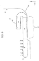
FIG. 6 shows a step involved in forming a three dimensional woven preform, according to one aspect of the invention. - The instant invention will now be described more fully hereinafter with reference to the accompanying drawings, in which preferred embodiments of the invention are shown. This invention may, however, be embodied in many different forms and should not be construed as limited to the illustrated embodiments set forth herein. Rather, these illustrated embodiments are provided so that this disclosure will be thorough and complete, and will fully convey the scope of the invention to those skilled in the art.
- In the following description, like reference characters designate like or corresponding parts throughout the figures. Additionally, in the following description, it is understood that such terms as "upper," "lower," "top," "bottom," "first," "second," and the like are words of convenience and are not to be construed as limiting terms.
- Turning now to the figures, the invention according to one embodiment is a method of fabricating a three dimensional woven preform for use in high-strength applications, such as for example, aircraft window frames, composite turbine fan cases, jet engine containment rings, aircraft fuselage frames or in flanged rings for attaching nacelles to aircraft engines. Although the preferred embodiments described herein relate to an aircraft window frame, the present invention is not limited as such. For example, the woven preforms or methods described herein may be used in the manufacture of any of the structures listed above, or the like. The method according to one exemplary embodiment uses a unique textile manufacturing technique, or what is known as "warp steering." The term "warp steering" refers to a differential take-up system for the warp yarns, which 'steers' them into a required shape, and allows straight weaving, polar weaving or a combination thereof to produce a preform that can practically take any shape in the X-Y plane of the fabric or preform. An example of such a preform in the form of a warp steered oval fabric produced using "steered" weaving, according to one aspect of the present invention, is shown in
FIG. 3 wherepreform 30 may be flat in one plane, and has a curved shape in the X-Y plane. In such an arrangement, eachwarp yarn 32 can have a different path length, similar to lines around a running track, while eachweft yarn 34 is always perpendicular or orthogonal to the edges of the fabric. This is to say that at points where aweft yarn 34 may be interwoven with one ormore warp yarns 32, theweft yarn 34 is always orthogonal to the one ormore warp yarns 32 irrespective of the curvilinear path thewarp yarns 32 take. - This technique may be used, according to one exemplary embodiment, to fabricate a composite window frame, such as that described with respect to
FIG. 1 , which includes features such as anupstanding leg 20 and a "joggle" 15, but does not require the darting required by conventional materials. The method according to this embodiment uses stretch broken carbon fibers ("SBCF") as circumferential fibers in selected regions so that the upstanding leg and joggle can be integrally formed into the preform. The woven preform as a result will have continuous fiber in the circumferential and radial directions of the frame. - Steered weaving according to this method can be carried out on a loom that uses a programmable differential take-up mechanism to produce the desired oval shape of the window frame. In the steered
fabric 30, the warp fiber may be continuous in the circumferential direction and the weft fiber is always oriented in the radial direction, relative to the local radius of curvature. - Multiple continuous layers of fabric can be laid on top of one another to build up the desired thickness. Additional layers of fabric with fibers oriented in off-axis directions (again, relative to the local radius of curvature) can also be interspersed between the layers of steered fabric if additional strength and/or stiffness is required. Alternatively, the steered fabric may be woven as a multilayer fabric where two or more layers of the multilayer fabric are integrally held by one or more warp and/or weft yarns in a desired pattern. The fabric can be woven using any convenient pattern for the warp fiber, i.e., ply-to-ply, through thickness angle interlock, orthogonal, etc. The fabric itself can be woven using any conventional weave pattern, such as plain, twill, satin etc. While carbon fiber is preferred, the invention may be applicable to practically any other fiber type including but not limited to those that can be stretch broken, e.g. stretch broken carbon fiber, glass, ceramic, and those that cannot be stretch broken or need not be stretch broken. For example, the fiber used in the present invention can be Discotex®, a discontinuous tow produced by Pepin Associates Inc., which when woven into a textile structure allows the textile structure to stretch in its reinforcement direction, permitting the formation of complex shapes from simple preform starting shapes.
- Discotex® is produced by cutting reinforcing yarns or tows into discrete lengths and aligning the cut yarns or tows to form a discontinuous tow. This tow is composed of long, discontinuous and overlapped reinforcing tow segments combined with aligned continuous fiber and an overwrap. The aligned continuous fiber and overwrap fiber are required to handle the DiscoTex® tow during textile operations but they can also be used as the matrix precursor material. In cases where the continuous fiber is not needed in later processing steps it can be removed to yield an all discontinuous textile material. DiscoTex® fabric stretching permits the rapid fabrication of complex contours while preserving fiber orientation and fiber volume fraction. Labor intensive cutting and darting of the fabric can be eliminated, and the technology is applicable to any type of reinforcing yarn including glass, carbon, and ceramic.
- It should be noted that the initial preform or
fabric 30 is flat. The final shape of the three dimensional preform, however, may be developed using a forming process to generate the upstanding leg, joggle, and general curved shape along the major axis. This forming depends on the use of SBCF in the warp direction of the steered fabric, which will allow the fabric to elongate as needed in the circumferential direction so that the preform is flat with no wrinkles. Conventional fiber may be used in the weft direction, and the width of the fabric may be set to the total arc length of the cross section. SBCF may be used in the weft direction if needed in some local geometry that requires the weft to stretch. When using SBCF, the actual forming process may be engineered to ensure that the total elongation required does not exceed the yield elongation limit of the fiber. - The method, according to one embodiment, can be carried out as illustrated in
FIGS. 4-5 . In this embodiment,woven preform 30 may be formed using SBCF as warp fiber in oneportion 36 of the fabric, for example, and conventional carbon fiber warp in anotherportion 38 of the fabric.Portion 36 may be, for example, the inner circumferential region of the oval preform, whileportion 38 may be, for example, the outer circumferential region. In this case theoutside edge 40 of thepreform 30 may be clamped to the top of a formingtool 45, for example, and thepreform 30 may be compressed into a female mold or formingtool surface 42. The SBCF inportion 36 elongate as the fibers are formed from the smaller radii of the initial preform into the larger radii of the final part. The compression ofpreform 30 into the female mold or formingtool surface 42 may be accomplished with radial compression, or using one of several known techniques. One such method may be using an inflatable tool that is pressurized to get uniform radial force on thepreform 30. Another method may use multiple section tooling to move and fix thepreform 30 into place under radial loading for subsequent molding. - It should be noted that the SBCF at the inner edge of the preform can have the highest percent elongation, and the maximum elongation depends on the height of the upstanding leg, the depth of the joggle, the total width of the preform, and the minimum local radius of curvature.
- The method according to another embodiment is illustrated in
FIG. 6 . In this embodiment,woven preform 30 may be formed, for example, using SBCF in the warp direction inedge portions 36, 36 (inner and outer circumferential regions of the oval preform or fabric 30), and conventional carbon fiber warp in thecenter portion 38 of the fabric. The portion of thepreform 30 that will become theupstanding leg 20 is actually woven so that it may be folded back over the main body of the preform. This feature is necessary to ensure that theupstanding leg 20 does not go into circumferential compression during forming. -
Preform 30 may be clamped into the tool over thearea 22 that contains the conventional warp fiber. Thejoggle 15 may be then formed by pressing the left side of thepreform 36 into themold 42, and theupstanding leg 20 may be formed by uniformly pushing theright side 36 of thepreform 30 up and out into themold 42. The compression ofpreform 30 into the female mold or formingtool surface 42 may be, as described earlier, accomplished with radial compression, or using one of the several known techniques. One such method may be using an inflatable tool that may be pressurized to get uniform radial force on thepreform 30. Another method may use multiple section tooling to move and fix thepreform 30 into place under radial loading for subsequent molding. - It should be noted that the SBCF warp at the inner edge of the preform will usually have the highest percent elongation, and it is this feature that will usually determine if either forming approach is feasible. The maximum elongation also depends on the height of the upstanding leg, the depth of the joggle, the total width of the preform, and the minimum local radius of curvature.
- After the fabric is molded to take the desired three dimensional shape, preform 30 can be processed into a composite using a conventional resin infusion method, such as resin transfer molding. For example, the preform according to one embodiment can be processed into an
aircraft window frame 10 as shown inFIG. 1 . Thestructure 10 comprises the woven preforms described in the previous embodiments. The preforms may be produced without cutting and darting of the individual plies. Eliminating these cuts and darts improves the strength as well as performance of the resulting structure. - The preforms of the present invention can be woven using any convenient pattern for the warp fiber, i.e., ply-to-ply, through thickness angle interlock, orthogonal, etc. While carbon fiber is preferred, the invention may be applicable to practically any other fiber type that can be stretch broken e.g., carbon, nylon, rayon, fiberglass, cotton, ceramic, aramid, polyester, and metal yarns or fibers.
- The warp steered fabric of the invention may be made from materials, such as for example, carbon, nylon, rayon, polyester, fiberglass, cotton, glass, ceramic, aramid, and polyethylene, or any other material commonly known in the art. The final structure may be impregnated with a matrix material, such as for example, epoxy, bismaleimide, polyester, vinyl-ester, ceramic, and carbon, using resin impregnation methods such as resin transfer molding or chemical vapor infiltration, thereby forming a three dimensional composite structure.
- Potential applications for the woven preform of the invention include any structural application that utilizes a contoured frame with a stiffened leg, although an aircraft window frame is described as an example herein.
- Although preferred embodiments of the present invention and modifications thereof have been described in detail herein, it is to be understood that this invention is not limited to this precise embodiment and modifications, and that other modifications and variations may be effected by one skilled in the art without departing from the scope of the appended claims.
Claims (29)
- A three dimensional woven preform (30) comprising:one or more layers of a warp steered fabric,characterized in that at least one portion of the steered fabric comprises a fiber in the warp direction (32) that allows the fabric stretch in a reinforcement direction,wherein the perform includesa first portion (36) of said warp steered fabric comprising the fiber in the warp direction (32) selected from the group of stretch broken fibers and discontinuous tows, anda second portion (38) of said warp steered fabric comprising conventional carbon fibers in the warp direction (32).
- The preform (30) of claim 1, wherein a portion of said warp steered fabric is compressed into a mold (42) to form an upstanding leg (20).
- The preform (30) of claim 2, wherein said preform (30) comprises the upstanding leg (20) and a joggle (15) in a body portion.
- The preform (30) of claim 3, wherein said body portion and upstanding leg (20) are integrally woven so there is continuous fiber across the preform (30).
- The preform (30) of claim 1, wherein a third portion (36) of said warp steered fabric comprises the fiber in the warp direction (32) selected from the group of stretch broken fibers and discontinuous tows.
- The preform (30) of claim 1, wherein said warp steered fabric is a multilayer fabric.
- The preform (30) of claim 1, wherein a warp fiber pattern in said warp steered fabric is a pattern selected from the group consisting of ply-to-ply, orthogonal, and angle interlock.
- The preform (30) of claim 1, wherein said warp steered fabric is formed by interweaving a plurality of warp (32) and weft (34) yarns or fibers, said warp (32) and weft (34) yarns or fibers being selected from the group consisting of carbon, nylon, rayon, fiberglass, cotton, ceramic, aramid, polyester, and metal yarns or fibers.
- The preform (30) of claim 1, further comprising one or more layers of fabric with fibers oriented in off-axis directions interspersed between the plurality of warp steered fabrics.
- A fiber reinforced composite comprising a three dimensional woven preform (30) according to claim 1, and further comprising a matrix material.
- The composite of claim 10, wherein said composite is a portion of a window frame (10).
- The composite of claim 11, wherein said composite is a portion of an aircraft window frame (10).
- The composite of claim 10, wherein said matrix material is a resin, and said composite is formed from a process selected from the group consisting of resin transfer molding and chemical vapor infiltration.
- The composite of claim 10, wherein said matrix material is selected from the group consisting of epoxy, bismaleimide, polyester, vinyl-ester, ceramic, and carbon.
- A method of forming a three dimensional woven preform (30), the method comprising the steps of:weaving a warp steered fabric; andthe method further characterized by laying one or more layers of said warp steered fabric to form a predetermined shape, wherein at least one portion of the steered fabric comprises a fiber in the warp direction (32) that allows the fabric to stretch in a reinforcement direction,wherein the perform includesa first portion (36) of said warp steered fabric comprising the fiber in the warp direction (32) selected from the group of stretch broken fibers and discontinuous tows, anda second portion (38) of said warp steered fabric comprising conventional carbon fibers in the warp direction (32).
- The method of claim 15, further comprising the step of compressing a portion of said warp steered fabric into a mold (42) so as to form an upstanding leg (20).
- The method of claim 16, further comprising the step of forming a joggle (15) in a body portion of said preform.
- The method of claim 17, wherein said body portion and upstanding leg (20) are integrally woven so there is continuous fiber across the perform (30).
- The method of claim 18, wherein said perform (30) is a portion of a window frame (10).
- The method of claim 19, wherein said preform (30) is a portion of an aircraft window frame (10).
- The method of claim 15, wherein a third portion of said warp steered fabric comprises the fiber in the warp direction (32) selected from the group of stretch broken fibers and discontinuous tows.
- The method of claim 15, wherein said warp steered fabric is woven on a loom equipped with a differential take-up mechanism.
- The method of claim 15, wherein said warp steered fabric is a multilayer fabric.
- The method of claim 23, wherein a warp fiber pattern in said warp steered fabric is a pattern selected from the group consisting of ply-to-ply, orthogonal, and angle interlock.
- The method of claim 15, wherein said warp steered fabric is formed by interweaving a plurality of warp (32) and weft (34) yarns or fibers, said warp (32) and weft (34) yarns or fibers being selected from the group consisting of carbon, nylon, rayon, fiberglass, cotton, ceramic, aramid, polyester, and metal yarns or fibers.
- A method of forming a fiber reinforced composite, the method comprising the steps of:forming a three dimensional woven preform (30) according to claim 15; andimpregnating said preform (30) in a matrix material.
- The method of claim 26, wherein said matrix material is a resin, and said composite is formed from a process selected from the group consisting of resin transfer molding and chemical vapor infiltration.
- The method of claim 26, wherein said matrix material is selected from the group consisting of epoxy, bismaleimide, polyester, vinyl-ester, ceramic, and carbon.
- The method of claim 15, further comprising the step of interspersing between the plurality of warp steered fabrics one or more layers of fabric with fibers oriented in off-axis directions.
Applications Claiming Priority (2)
| Application Number | Priority Date | Filing Date | Title |
|---|---|---|---|
| US24780809P | 2009-10-01 | 2009-10-01 | |
| PCT/US2010/050749 WO2011041435A1 (en) | 2009-10-01 | 2010-09-29 | Woven preform, composite, and method of making thereof |
Publications (2)
| Publication Number | Publication Date |
|---|---|
| EP2483045A1 EP2483045A1 (en) | 2012-08-08 |
| EP2483045B1 true EP2483045B1 (en) | 2017-08-02 |
Family
ID=43416926
Family Applications (1)
| Application Number | Title | Priority Date | Filing Date |
|---|---|---|---|
| EP10765880.9A Active EP2483045B1 (en) | 2009-10-01 | 2010-09-29 | Woven preform, composite, and method of making thereof |
Country Status (13)
| Country | Link |
|---|---|
| US (2) | US8969223B2 (en) |
| EP (1) | EP2483045B1 (en) |
| JP (1) | JP5872471B2 (en) |
| KR (1) | KR101886877B1 (en) |
| CN (1) | CN102666050B (en) |
| BR (1) | BR112012007154B1 (en) |
| CA (1) | CA2775894C (en) |
| ES (1) | ES2645412T3 (en) |
| MX (1) | MX2012003668A (en) |
| RU (1) | RU2550860C2 (en) |
| TW (1) | TWI526587B (en) |
| WO (1) | WO2011041435A1 (en) |
| ZA (1) | ZA201202330B (en) |
Families Citing this family (16)
| Publication number | Priority date | Publication date | Assignee | Title |
|---|---|---|---|---|
| FR2988324B1 (en) * | 2012-03-23 | 2014-04-25 | Daher Aerospace | METHOD FOR MANUFACTURING A FRAME FRAME IN COMPOSITE MATERIAL WITH FIBROUS REINFORCEMENT AND PORTRAW OBTAINED BY SUCH A METHOD |
| US9493909B2 (en) * | 2012-07-24 | 2016-11-15 | Liquidmetal Coatings, Llc | Fiber-containing composites |
| CN103317733B (en) * | 2012-10-12 | 2015-04-15 | 北京航空航天大学 | Carriage covering composite material with silkworm cocoon-imitating winded and braided structure and preparation method thereof |
| US20140255646A1 (en) | 2013-03-08 | 2014-09-11 | The Boeing Company | Forming Composite Features Using Steered Discontinuous Fiber Pre-Preg |
| FR3043355B1 (en) * | 2015-11-06 | 2017-12-22 | Safran | METHOD FOR MANUFACTURING A COMPOSITE MATERIAL PART COMPRISING A SOLIDARY BODY OF ONE OR MORE PLATFORMS |
| CN105366073B (en) * | 2015-11-24 | 2017-04-12 | 江苏恒神股份有限公司 | Method for manufacturing fiber-laid and seamed window frame precast body |
| US10814602B2 (en) | 2016-09-14 | 2020-10-27 | The Boeing Company | Method of producing cored composite parts |
| FR3062659B1 (en) * | 2017-02-03 | 2019-03-22 | Safran Aircraft Engines | CALL FOR PREFORM IN A JACQUARD-TYPE WEAVING |
| EP3830324B1 (en) * | 2018-08-01 | 2022-10-12 | Albany Engineered Composites, Inc. | Method of making a curved preform |
| CN109208155A (en) * | 2018-09-27 | 2019-01-15 | 西安工程大学 | A method of preparing scribbled and three dimensional fabric prefabricated component |
| CN109518340A (en) * | 2019-01-11 | 2019-03-26 | 深圳市奔雷材料制品有限公司 | A kind of fiber multi-angle braiding composite felt and its manufacturing method and manufacturing device |
| FR3106519B1 (en) * | 2020-01-28 | 2022-01-28 | Safran | Woven fibrous preform for making a composite material part, in particular a turbine engine blade |
| WO2021200047A1 (en) * | 2020-03-31 | 2021-10-07 | 川崎重工業株式会社 | Method for producing intermediate product of airplane component, and airplane component |
| CN113752588B (en) * | 2020-06-03 | 2022-07-01 | 上海飞机制造有限公司 | A method of manufacturing an aircraft bulkhead |
| US12064902B2 (en) * | 2021-11-19 | 2024-08-20 | GM Global Technology Operations LLC | System and method of forming a fiber preform for use in manufacturing a component made of a composite material |
| TWI821018B (en) * | 2022-11-14 | 2023-11-01 | 天下長榮科技有限公司 | intertwined fiber composites |
Family Cites Families (40)
| Publication number | Priority date | Publication date | Assignee | Title |
|---|---|---|---|---|
| SU921876A1 (en) * | 1980-06-20 | 1982-04-23 | Институт Механики Полимеров Ан Латвсср | Reinforced cryogenic insulation material |
| US4837117A (en) * | 1986-12-16 | 1989-06-06 | E. I. Du Pont De Nemours And Company | Composites of stretch broken aligned fibers of carbon and glass reinforced resin |
| US4856146A (en) * | 1986-12-16 | 1989-08-15 | E. I. Du Pont De Nemours And Company | Comosites of stretch broken aligned fibers of carbon and glass reinforced resin |
| US4857385A (en) * | 1986-12-16 | 1989-08-15 | E. I. Du Pont De Nemours And Company | Composites of stretch broken aligned fibers of carbon and glass reinforced resin |
| US4856147A (en) * | 1986-12-16 | 1989-08-15 | E. I. Du Pont De Nemours And Company | Composites of stretch broken aligned fibers of carbon and glass reinforced resin |
| US4759985A (en) * | 1986-12-16 | 1988-07-26 | E. I. Du Pont De Nemours And Company | Composites of stretch broken aligned fibers of carbon and glass reinforced resin |
| US5394906A (en) * | 1993-02-10 | 1995-03-07 | The United States Of America As Represented By The Administrator Of The National Aeronautics And Space Administration | Method and apparatus for weaving curved material preforms |
| US5436042A (en) * | 1994-03-11 | 1995-07-25 | The Carborundum Company | Ceramic fiber-reinforced composite articles and their production |
| EP0675155B1 (en) * | 1994-03-31 | 2002-06-12 | Toray Industries, Inc. | Woven carbon fiber fabric prepreg precursor, prepreg and processes for producing them |
| US5546880A (en) * | 1994-12-29 | 1996-08-20 | The Bf Goodrich Company | Annular filamentary structures and methods of making |
| JP3633197B2 (en) * | 1997-04-09 | 2005-03-30 | 東レ株式会社 | Carbon fiber fabric and method for producing the same |
| JP2002003280A (en) * | 2000-06-20 | 2002-01-09 | Toray Ind Inc | Carbon fiber reinforced carbon sliding member and method of manufacturing the same |
| JP3620021B2 (en) * | 2001-01-12 | 2005-02-16 | 中部電力株式会社 | High-speed rotating body for power storage flywheel |
| US6446675B1 (en) * | 2001-07-05 | 2002-09-10 | Albany International Techniweave, Inc. | Minimum distortion 3D woven preforms |
| US6477740B1 (en) * | 2001-12-12 | 2002-11-12 | Hexcel Corporation | Stretch breaking of fibers |
| EP1342553B1 (en) * | 2002-03-08 | 2016-05-18 | Airbus Operations GmbH | Process for producing a fiber reinforced composite windowframe for airplanes and apparatus to implement the method |
| WO2004016844A1 (en) * | 2002-08-12 | 2004-02-26 | Shikibo Ltd. | Preform precursor for fiber-reinforced composite material, preform for fiber-reinforced composite material, and method of manufacturing the precursor and the preform |
| US6818306B2 (en) * | 2002-09-27 | 2004-11-16 | The Boeing Company | Optically clear structural laminate |
| WO2004076216A2 (en) * | 2003-02-27 | 2004-09-10 | Sierracin/Sylmar Corporation | Window frame/seal assembly and method of forming the same |
| JP4629671B2 (en) * | 2003-07-23 | 2011-02-09 | ピーピージー・インダストリーズ・オハイオ・インコーポレイテッド | Composite sealing device and window assembly |
| US7300693B2 (en) * | 2003-09-04 | 2007-11-27 | The Boeing Company | Resin infused transparent skin panel and method of making same |
| JP4309748B2 (en) * | 2003-11-25 | 2009-08-05 | シキボウ株式会社 | Dry preform for FRP window frames used in aircraft |
| US6935197B2 (en) * | 2004-01-26 | 2005-08-30 | The Boeing Company | Method and apparatus for testing uncured prepreg material |
| US7045084B1 (en) | 2004-02-17 | 2006-05-16 | Northrop Grumman Corporation | Process for making a curved preform made from woven composite materials |
| US7028950B2 (en) * | 2004-05-10 | 2006-04-18 | The Boeing Company | Load bearing window |
| DE102004025380B4 (en) * | 2004-05-24 | 2011-01-13 | Airbus Operations Gmbh | Window frame for aircraft |
| DE102004025381B4 (en) | 2004-05-24 | 2014-01-23 | Airbus Operations Gmbh | Window frame for aircraft |
| US7530531B2 (en) * | 2004-10-04 | 2009-05-12 | The Boeing Company | Apparatus and methods for installing an aircraft window panel |
| US7713893B2 (en) * | 2004-12-08 | 2010-05-11 | Albany Engineered Composites, Inc. | Three-dimensional woven integrally stiffened panel |
| US7563497B2 (en) * | 2004-12-27 | 2009-07-21 | Mkp Structural Design Associates, Inc. | Lightweight, rigid composite structures |
| US7214425B2 (en) | 2005-02-10 | 2007-05-08 | Supreme Elastic Corporation | High performance fiber blend and products made therefrom |
| US7281686B2 (en) * | 2005-11-02 | 2007-10-16 | The Boeing Company | Window assembly for aircraft fuselage |
| CN101313106A (en) * | 2005-11-25 | 2008-11-26 | 东丽株式会社 | Carbon fiber bundles, preforms and carbon fiber reinforced composites |
| US7552896B2 (en) * | 2006-02-21 | 2009-06-30 | The Boeing Company | Aircraft window assembly |
| US20080078876A1 (en) | 2006-08-15 | 2008-04-03 | Baggette Phillip D | Composite resin window frame constructions for airplanes |
| US7988094B2 (en) * | 2007-01-12 | 2011-08-02 | Scott Ernest Ostrem | Aircraft window erosion shield |
| BRPI0820472A2 (en) * | 2007-11-09 | 2016-11-08 | Nordam Group Inc | dual panel manufacturing |
| CN101910493B (en) * | 2008-01-11 | 2013-07-24 | 东丽株式会社 | Reinforcing fiber base of curved shape, layered product employing the same, preform, fiber-reinforced resin composite material, and processes for producing these |
| US8440276B2 (en) | 2008-02-11 | 2013-05-14 | Albany Engineered Composites, Inc. | Multidirectionally reinforced shape woven preforms for composite structures |
| DE102008051121B4 (en) | 2008-10-09 | 2013-03-28 | Airbus Operations Gmbh | Device and method for draping and preforming curved profile structure parts of fiber-knitted fabrics |
-
2010
- 2010-09-29 US US12/893,866 patent/US8969223B2/en active Active
- 2010-09-29 JP JP2012532279A patent/JP5872471B2/en active Active
- 2010-09-29 RU RU2012113098/05A patent/RU2550860C2/en active
- 2010-09-29 MX MX2012003668A patent/MX2012003668A/en active IP Right Grant
- 2010-09-29 CA CA2775894A patent/CA2775894C/en active Active
- 2010-09-29 CN CN201080053418.9A patent/CN102666050B/en active Active
- 2010-09-29 BR BR112012007154A patent/BR112012007154B1/en active IP Right Grant
- 2010-09-29 WO PCT/US2010/050749 patent/WO2011041435A1/en not_active Ceased
- 2010-09-29 EP EP10765880.9A patent/EP2483045B1/en active Active
- 2010-09-29 KR KR1020127011188A patent/KR101886877B1/en active Active
- 2010-09-29 ES ES10765880.9T patent/ES2645412T3/en active Active
- 2010-09-30 TW TW099133280A patent/TWI526587B/en active
-
2012
- 2012-03-30 ZA ZA2012/02330A patent/ZA201202330B/en unknown
-
2015
- 2015-01-22 US US14/602,861 patent/US10190240B2/en active Active
Non-Patent Citations (1)
| Title |
|---|
| None * |
Also Published As
| Publication number | Publication date |
|---|---|
| US8969223B2 (en) | 2015-03-03 |
| US20150132487A1 (en) | 2015-05-14 |
| KR101886877B1 (en) | 2018-08-08 |
| TW201128008A (en) | 2011-08-16 |
| CN102666050B (en) | 2015-09-16 |
| WO2011041435A1 (en) | 2011-04-07 |
| BR112012007154B1 (en) | 2019-12-10 |
| BR112012007154A2 (en) | 2016-03-29 |
| JP5872471B2 (en) | 2016-03-01 |
| RU2550860C2 (en) | 2015-05-20 |
| MX2012003668A (en) | 2012-06-27 |
| ZA201202330B (en) | 2013-09-25 |
| ES2645412T3 (en) | 2017-12-05 |
| CA2775894C (en) | 2017-07-25 |
| CN102666050A (en) | 2012-09-12 |
| KR20120091168A (en) | 2012-08-17 |
| TWI526587B (en) | 2016-03-21 |
| EP2483045A1 (en) | 2012-08-08 |
| CA2775894A1 (en) | 2011-04-07 |
| RU2012113098A (en) | 2013-11-10 |
| US10190240B2 (en) | 2019-01-29 |
| JP2013506767A (en) | 2013-02-28 |
| US20110086566A1 (en) | 2011-04-14 |
Similar Documents
| Publication | Publication Date | Title |
|---|---|---|
| CA2775894C (en) | Woven preform, composite, and method of making thereof | |
| EP2483044B1 (en) | Woven preform, composite, and method of making thereof | |
| EP2242645B1 (en) | Multidirectionally reinforced shape woven preforms for composite structures | |
| EP2630282B1 (en) | Tubular woven preform, fiber reinforced composites and methods of making thereof | |
| US11192312B2 (en) | Three-dimensional woven preforms for omega stiffeners |
Legal Events
| Date | Code | Title | Description |
|---|---|---|---|
| PUAI | Public reference made under article 153(3) epc to a published international application that has entered the european phase |
Free format text: ORIGINAL CODE: 0009012 |
|
| 17P | Request for examination filed |
Effective date: 20120329 |
|
| AK | Designated contracting states |
Kind code of ref document: A1 Designated state(s): AL AT BE BG CH CY CZ DE DK EE ES FI FR GB GR HR HU IE IS IT LI LT LU LV MC MK MT NL NO PL PT RO SE SI SK SM TR |
|
| DAX | Request for extension of the european patent (deleted) | ||
| 17Q | First examination report despatched |
Effective date: 20130613 |
|
| GRAP | Despatch of communication of intention to grant a patent |
Free format text: ORIGINAL CODE: EPIDOSNIGR1 |
|
| INTG | Intention to grant announced |
Effective date: 20170216 |
|
| GRAS | Grant fee paid |
Free format text: ORIGINAL CODE: EPIDOSNIGR3 |
|
| GRAA | (expected) grant |
Free format text: ORIGINAL CODE: 0009210 |
|
| AK | Designated contracting states |
Kind code of ref document: B1 Designated state(s): AL AT BE BG CH CY CZ DE DK EE ES FI FR GB GR HR HU IE IS IT LI LT LU LV MC MK MT NL NO PL PT RO SE SI SK SM TR |
|
| REG | Reference to a national code |
Ref country code: GB Ref legal event code: FG4D |
|
| REG | Reference to a national code |
Ref country code: CH Ref legal event code: EP Ref country code: AT Ref legal event code: REF Ref document number: 913954 Country of ref document: AT Kind code of ref document: T Effective date: 20170815 |
|
| REG | Reference to a national code |
Ref country code: IE Ref legal event code: FG4D |
|
| REG | Reference to a national code |
Ref country code: DE Ref legal event code: R096 Ref document number: 602010044089 Country of ref document: DE |
|
| REG | Reference to a national code |
Ref country code: FR Ref legal event code: PLFP Year of fee payment: 8 |
|
| REG | Reference to a national code |
Ref country code: NL Ref legal event code: FP |
|
| REG | Reference to a national code |
Ref country code: SE Ref legal event code: TRGR |
|
| REG | Reference to a national code |
Ref country code: CH Ref legal event code: NV Representative=s name: MOINAS AND SAVOYE SARL, CH |
|
| PGFP | Annual fee paid to national office [announced via postgrant information from national office to epo] |
Ref country code: NL Payment date: 20170926 Year of fee payment: 8 |
|
| REG | Reference to a national code |
Ref country code: ES Ref legal event code: FG2A Ref document number: 2645412 Country of ref document: ES Kind code of ref document: T3 Effective date: 20171205 |
|
| REG | Reference to a national code |
Ref country code: LT Ref legal event code: MG4D |
|
| PG25 | Lapsed in a contracting state [announced via postgrant information from national office to epo] |
Ref country code: NO Free format text: LAPSE BECAUSE OF FAILURE TO SUBMIT A TRANSLATION OF THE DESCRIPTION OR TO PAY THE FEE WITHIN THE PRESCRIBED TIME-LIMIT Effective date: 20171102 Ref country code: LT Free format text: LAPSE BECAUSE OF FAILURE TO SUBMIT A TRANSLATION OF THE DESCRIPTION OR TO PAY THE FEE WITHIN THE PRESCRIBED TIME-LIMIT Effective date: 20170802 Ref country code: HR Free format text: LAPSE BECAUSE OF FAILURE TO SUBMIT A TRANSLATION OF THE DESCRIPTION OR TO PAY THE FEE WITHIN THE PRESCRIBED TIME-LIMIT Effective date: 20170802 |
|
| PG25 | Lapsed in a contracting state [announced via postgrant information from national office to epo] |
Ref country code: LV Free format text: LAPSE BECAUSE OF FAILURE TO SUBMIT A TRANSLATION OF THE DESCRIPTION OR TO PAY THE FEE WITHIN THE PRESCRIBED TIME-LIMIT Effective date: 20170802 Ref country code: BG Free format text: LAPSE BECAUSE OF FAILURE TO SUBMIT A TRANSLATION OF THE DESCRIPTION OR TO PAY THE FEE WITHIN THE PRESCRIBED TIME-LIMIT Effective date: 20171102 Ref country code: IS Free format text: LAPSE BECAUSE OF FAILURE TO SUBMIT A TRANSLATION OF THE DESCRIPTION OR TO PAY THE FEE WITHIN THE PRESCRIBED TIME-LIMIT Effective date: 20171202 Ref country code: PL Free format text: LAPSE BECAUSE OF FAILURE TO SUBMIT A TRANSLATION OF THE DESCRIPTION OR TO PAY THE FEE WITHIN THE PRESCRIBED TIME-LIMIT Effective date: 20170802 Ref country code: GR Free format text: LAPSE BECAUSE OF FAILURE TO SUBMIT A TRANSLATION OF THE DESCRIPTION OR TO PAY THE FEE WITHIN THE PRESCRIBED TIME-LIMIT Effective date: 20171103 |
|
| PG25 | Lapsed in a contracting state [announced via postgrant information from national office to epo] |
Ref country code: DK Free format text: LAPSE BECAUSE OF FAILURE TO SUBMIT A TRANSLATION OF THE DESCRIPTION OR TO PAY THE FEE WITHIN THE PRESCRIBED TIME-LIMIT Effective date: 20170802 Ref country code: RO Free format text: LAPSE BECAUSE OF FAILURE TO SUBMIT A TRANSLATION OF THE DESCRIPTION OR TO PAY THE FEE WITHIN THE PRESCRIBED TIME-LIMIT Effective date: 20170802 |
|
| REG | Reference to a national code |
Ref country code: DE Ref legal event code: R097 Ref document number: 602010044089 Country of ref document: DE |
|
| PG25 | Lapsed in a contracting state [announced via postgrant information from national office to epo] |
Ref country code: EE Free format text: LAPSE BECAUSE OF FAILURE TO SUBMIT A TRANSLATION OF THE DESCRIPTION OR TO PAY THE FEE WITHIN THE PRESCRIBED TIME-LIMIT Effective date: 20170802 Ref country code: SK Free format text: LAPSE BECAUSE OF FAILURE TO SUBMIT A TRANSLATION OF THE DESCRIPTION OR TO PAY THE FEE WITHIN THE PRESCRIBED TIME-LIMIT Effective date: 20170802 Ref country code: SM Free format text: LAPSE BECAUSE OF FAILURE TO SUBMIT A TRANSLATION OF THE DESCRIPTION OR TO PAY THE FEE WITHIN THE PRESCRIBED TIME-LIMIT Effective date: 20170802 Ref country code: MC Free format text: LAPSE BECAUSE OF FAILURE TO SUBMIT A TRANSLATION OF THE DESCRIPTION OR TO PAY THE FEE WITHIN THE PRESCRIBED TIME-LIMIT Effective date: 20170802 |
|
| PLBE | No opposition filed within time limit |
Free format text: ORIGINAL CODE: 0009261 |
|
| STAA | Information on the status of an ep patent application or granted ep patent |
Free format text: STATUS: NO OPPOSITION FILED WITHIN TIME LIMIT |
|
| REG | Reference to a national code |
Ref country code: IE Ref legal event code: MM4A |
|
| PG25 | Lapsed in a contracting state [announced via postgrant information from national office to epo] |
Ref country code: LU Free format text: LAPSE BECAUSE OF NON-PAYMENT OF DUE FEES Effective date: 20170929 |
|
| 26N | No opposition filed |
Effective date: 20180503 |
|
| PG25 | Lapsed in a contracting state [announced via postgrant information from national office to epo] |
Ref country code: IE Free format text: LAPSE BECAUSE OF NON-PAYMENT OF DUE FEES Effective date: 20170929 |
|
| PG25 | Lapsed in a contracting state [announced via postgrant information from national office to epo] |
Ref country code: SI Free format text: LAPSE BECAUSE OF FAILURE TO SUBMIT A TRANSLATION OF THE DESCRIPTION OR TO PAY THE FEE WITHIN THE PRESCRIBED TIME-LIMIT Effective date: 20170802 |
|
| REG | Reference to a national code |
Ref country code: FR Ref legal event code: PLFP Year of fee payment: 9 |
|
| PG25 | Lapsed in a contracting state [announced via postgrant information from national office to epo] |
Ref country code: MT Free format text: LAPSE BECAUSE OF NON-PAYMENT OF DUE FEES Effective date: 20170929 |
|
| REG | Reference to a national code |
Ref country code: NL Ref legal event code: MM Effective date: 20181001 |
|
| PG25 | Lapsed in a contracting state [announced via postgrant information from national office to epo] |
Ref country code: HU Free format text: LAPSE BECAUSE OF FAILURE TO SUBMIT A TRANSLATION OF THE DESCRIPTION OR TO PAY THE FEE WITHIN THE PRESCRIBED TIME-LIMIT; INVALID AB INITIO Effective date: 20100929 Ref country code: NL Free format text: LAPSE BECAUSE OF NON-PAYMENT OF DUE FEES Effective date: 20181001 |
|
| PG25 | Lapsed in a contracting state [announced via postgrant information from national office to epo] |
Ref country code: CY Free format text: LAPSE BECAUSE OF NON-PAYMENT OF DUE FEES Effective date: 20170802 |
|
| PG25 | Lapsed in a contracting state [announced via postgrant information from national office to epo] |
Ref country code: MK Free format text: LAPSE BECAUSE OF FAILURE TO SUBMIT A TRANSLATION OF THE DESCRIPTION OR TO PAY THE FEE WITHIN THE PRESCRIBED TIME-LIMIT Effective date: 20170802 |
|
| PG25 | Lapsed in a contracting state [announced via postgrant information from national office to epo] |
Ref country code: TR Free format text: LAPSE BECAUSE OF FAILURE TO SUBMIT A TRANSLATION OF THE DESCRIPTION OR TO PAY THE FEE WITHIN THE PRESCRIBED TIME-LIMIT Effective date: 20170802 |
|
| PG25 | Lapsed in a contracting state [announced via postgrant information from national office to epo] |
Ref country code: PT Free format text: LAPSE BECAUSE OF FAILURE TO SUBMIT A TRANSLATION OF THE DESCRIPTION OR TO PAY THE FEE WITHIN THE PRESCRIBED TIME-LIMIT Effective date: 20170802 |
|
| PG25 | Lapsed in a contracting state [announced via postgrant information from national office to epo] |
Ref country code: AL Free format text: LAPSE BECAUSE OF FAILURE TO SUBMIT A TRANSLATION OF THE DESCRIPTION OR TO PAY THE FEE WITHIN THE PRESCRIBED TIME-LIMIT Effective date: 20170802 |
|
| PGFP | Annual fee paid to national office [announced via postgrant information from national office to epo] |
Ref country code: CH Payment date: 20201002 Year of fee payment: 11 |
|
| REG | Reference to a national code |
Ref country code: AT Ref legal event code: UEP Ref document number: 913954 Country of ref document: AT Kind code of ref document: T Effective date: 20170802 |
|
| PGFP | Annual fee paid to national office [announced via postgrant information from national office to epo] |
Ref country code: AT Payment date: 20210901 Year of fee payment: 12 Ref country code: CZ Payment date: 20210908 Year of fee payment: 12 |
|
| REG | Reference to a national code |
Ref country code: CH Ref legal event code: PL |
|
| PG25 | Lapsed in a contracting state [announced via postgrant information from national office to epo] |
Ref country code: LI Free format text: LAPSE BECAUSE OF NON-PAYMENT OF DUE FEES Effective date: 20210930 Ref country code: CH Free format text: LAPSE BECAUSE OF NON-PAYMENT OF DUE FEES Effective date: 20210930 |
|
| PGFP | Annual fee paid to national office [announced via postgrant information from national office to epo] |
Ref country code: BE Payment date: 20220927 Year of fee payment: 13 |
|
| PG25 | Lapsed in a contracting state [announced via postgrant information from national office to epo] |
Ref country code: CZ Free format text: LAPSE BECAUSE OF NON-PAYMENT OF DUE FEES Effective date: 20220929 |
|
| REG | Reference to a national code |
Ref country code: AT Ref legal event code: MM01 Ref document number: 913954 Country of ref document: AT Kind code of ref document: T Effective date: 20220929 |
|
| P01 | Opt-out of the competence of the unified patent court (upc) registered |
Effective date: 20230613 |
|
| PG25 | Lapsed in a contracting state [announced via postgrant information from national office to epo] |
Ref country code: AT Free format text: LAPSE BECAUSE OF NON-PAYMENT OF DUE FEES Effective date: 20220929 |
|
| REG | Reference to a national code |
Ref country code: DE Ref legal event code: R082 Ref document number: 602010044089 Country of ref document: DE Representative=s name: SONNENBERG HARRISON PARTNERSCHAFT MBB PATENT- , DE |
|
| REG | Reference to a national code |
Ref country code: BE Ref legal event code: MM Effective date: 20230930 |
|
| PG25 | Lapsed in a contracting state [announced via postgrant information from national office to epo] |
Ref country code: BE Free format text: LAPSE BECAUSE OF NON-PAYMENT OF DUE FEES Effective date: 20230930 |
|
| PGFP | Annual fee paid to national office [announced via postgrant information from national office to epo] |
Ref country code: FI Payment date: 20250925 Year of fee payment: 16 |
|
| PGFP | Annual fee paid to national office [announced via postgrant information from national office to epo] |
Ref country code: DE Payment date: 20250929 Year of fee payment: 16 |
|
| PGFP | Annual fee paid to national office [announced via postgrant information from national office to epo] |
Ref country code: IT Payment date: 20250919 Year of fee payment: 16 |
|
| PGFP | Annual fee paid to national office [announced via postgrant information from national office to epo] |
Ref country code: GB Payment date: 20250929 Year of fee payment: 16 |
|
| PGFP | Annual fee paid to national office [announced via postgrant information from national office to epo] |
Ref country code: FR Payment date: 20250925 Year of fee payment: 16 |
|
| PGFP | Annual fee paid to national office [announced via postgrant information from national office to epo] |
Ref country code: SE Payment date: 20250927 Year of fee payment: 16 |
|
| PGFP | Annual fee paid to national office [announced via postgrant information from national office to epo] |
Ref country code: ES Payment date: 20251001 Year of fee payment: 16 |