EP2482782B1 - Wheelchair for heavy persons - Google Patents
Wheelchair for heavy persons Download PDFInfo
- Publication number
- EP2482782B1 EP2482782B1 EP10765524.3A EP10765524A EP2482782B1 EP 2482782 B1 EP2482782 B1 EP 2482782B1 EP 10765524 A EP10765524 A EP 10765524A EP 2482782 B1 EP2482782 B1 EP 2482782B1
- Authority
- EP
- European Patent Office
- Prior art keywords
- wheelchair
- footrest
- tubular segments
- rod
- calfrest
- Prior art date
- Legal status (The legal status is an assumption and is not a legal conclusion. Google has not performed a legal analysis and makes no representation as to the accuracy of the status listed.)
- Active
Links
Images




Classifications
-
- A—HUMAN NECESSITIES
- A61—MEDICAL OR VETERINARY SCIENCE; HYGIENE
- A61G—TRANSPORT, PERSONAL CONVEYANCES, OR ACCOMMODATION SPECIALLY ADAPTED FOR PATIENTS OR DISABLED PERSONS; OPERATING TABLES OR CHAIRS; CHAIRS FOR DENTISTRY; FUNERAL DEVICES
- A61G5/00—Chairs or personal conveyances specially adapted for patients or disabled persons, e.g. wheelchairs
- A61G5/10—Parts, details or accessories
- A61G5/12—Rests specially adapted therefor, e.g. for the head or the feet
-
- A—HUMAN NECESSITIES
- A61—MEDICAL OR VETERINARY SCIENCE; HYGIENE
- A61G—TRANSPORT, PERSONAL CONVEYANCES, OR ACCOMMODATION SPECIALLY ADAPTED FOR PATIENTS OR DISABLED PERSONS; OPERATING TABLES OR CHAIRS; CHAIRS FOR DENTISTRY; FUNERAL DEVICES
- A61G5/00—Chairs or personal conveyances specially adapted for patients or disabled persons, e.g. wheelchairs
- A61G5/10—Parts, details or accessories
- A61G5/12—Rests specially adapted therefor, e.g. for the head or the feet
- A61G5/127—Rests specially adapted therefor, e.g. for the head or the feet for lower legs
-
- A—HUMAN NECESSITIES
- A61—MEDICAL OR VETERINARY SCIENCE; HYGIENE
- A61G—TRANSPORT, PERSONAL CONVEYANCES, OR ACCOMMODATION SPECIALLY ADAPTED FOR PATIENTS OR DISABLED PERSONS; OPERATING TABLES OR CHAIRS; CHAIRS FOR DENTISTRY; FUNERAL DEVICES
- A61G5/00—Chairs or personal conveyances specially adapted for patients or disabled persons, e.g. wheelchairs
- A61G5/10—Parts, details or accessories
- A61G5/12—Rests specially adapted therefor, e.g. for the head or the feet
- A61G5/128—Rests specially adapted therefor, e.g. for the head or the feet for feet
Definitions
- the present invention relates to a wheelchair provided with two legrests, each legrest comprising a frame part and, connected thereto, a footrest.
- the legrest usually comprises a frame part which is connected centrally to the wheelchair frame and which is often provided with a footrest and a calfrest.
- a footrest and calfrest contribute to the comfort of the user seated in the wheelchair.
- each legrest has its own footrest and calfrest.
- these conventional wheelchairs are not adapted to the needs of heavy disabled persons. Indeed, for these persons, the wheelchair frame is wider and only a single footrest, connected at both ends to the right and left legrests, is used.
- the problem in this solution is the great difficulty to transfer the user in or from the wheelchair, due to the presence of this footrest.
- the footrest For improving this, it has already been proposed to design the footrest to be pivotable so that prior to a transfer, it can temporarily be pivoted sideways.
- the legs of the user seated in the wheelchair are to be lifted from the path of travel of the footrest pivoting by. This leads to a very uncomfortable sitting posture for the user and requires substantial physical effort from the assistant, especially considering the high weight of the user's legs.
- the aim of the present invention is therefore to provide a wheelchair for heavy persons, wherein the drawback mentioned of the known wheelchairs is avoided.
- each legrest comprising a frame part and, connected thereto, a footrest, wherein each footrest comprises at one of their ends, namely connecting end, first connecting means so as to detachably connect an extension plate between said connecting ends.
- each footrest comprises disconnecting means configured to act on said first connecting means so as to disconnect the extension plate from said connecting ends.
- the extension plate may comprise second connecting means at each of its lateral ends configured to interact with said first connecting means so as to be detachably connected to the footrests
- said first connecting means may comprise a rod extending along the connecting end of each footrest, said rod having series of first tubular segments separated by series of second tubular segments, the diameter of said first tubular segments being lower than the diameter of said second tubular segments
- said second connecting means may comprise series of connecting elements spaced apart along the lateral ends of the extension plate, said connecting elements having a slot formed inside, said slot comprising a first portion in which only said first tubular segments can be introduced and a second portion having a tubular form and approximately the same diameter than said second tubular segments
- disconnecting means may comprise a button fixedly connected to said rod, said button acting on said rod so as to move said first tubular segments in front of said connecting elements, and wherein a spring positioned inside each footrest may act on said rod so as to move said second tubular segments in front of said connecting elements.
- Each footrest may be pivotally connected to said frame part.
- Said wheelchair may comprise a wheelchair frame and, connected at each side thereof, a calfrest, wherein said calfrest may be movably connected to said wheelchair frame, and wherein said calfrest may be detachably connected to said wheelchair frame.
- the footrest assembly made in one piece before the transfer of the user can be splitted in three parts, the middle part being temporarily removed and the two external parts keeping attached to the legrests. Consequently, the user can place one of his feet outside of the footrest by the open space previously occupied by the middle part so as to move it to the floor. At the same time, and optionally, it is also possible to pivot sideways the external part of the footrest on which rested said foot. The same action can be repeated for the second foot of the user so that the user is completely transferred from the wheelchair. Accordingly, the solution of the invention avoids high physical effort for the assistant and uncomfortable sitting posture for the user.
- the footrest assembly 10 comprises two external parts 1 and a middle part 2.
- Each external part 1 constitutes a conventional footrest of a wheelchair and is pivotally connected to the frame part 3 of a legrest, respectively positioned at the left and at the right side of the wheelchair frame.
- the middle part 2 constitutes an extension plate that is detachably connected to said external parts 1 at its two lateral ends 5.
- the connection between said external parts 1 and said middle part 2 can be achieved for instance by positioning a first connecting means at the ends 4 of said external parts 1 that are in contact with the lateral ends 5 of said middle part 2, hereinafter referred to as connecting ends 4, said first connecting means being configured so as to interact with second connecting means positioned at each lateral end 5 of said middle part 2.
- first and second connecting means will be described afterwards in relation to Figure 4 to 6 .
- first connecting means could consist in at least one clip or claw positioned on the border of the connecting ends 4 and configured to pinch an external wall of the middle part 2, positioned at each lateral end of said middle part 2.
- each external part 1 will be advantageously provided with disconnecting means 6.
- disconnecting means could also be integrated to the middle part 2.
- disconnecting means are only optional and specific embodiments of the present invention could also be proposed without disconnecting means. In this case, the user must act directly on the first connecting means to detach the middle part 2 from the external parts 1.
- an assistant decides to transfer a user from the wheelchair of the present invention, he begins to remove the middle part 2 from the rest of the footrest assembly 10 (see Figure 2 ). For doing this, he must firstly activate the disconnecting means 6 positioned on one external face of the external parts 1 so that the interaction between first connecting means and second connecting means is stopped, leading to the disconnection between said external parts 1 and said middle part 2. However, in this position, mechanical pieces of the middle part 2 or of the external parts 1 can still prevent the removal of said middle part 2. So, to completely remove said middle part 2, it is necessary to push aside the frame part 3 of each legrest so that each external part 1 can be separed from the middle part 2.
- FIG. 4 shows that said first connecting means comprise a rod 7 extending along the connecting end 4 of said external part 1, said rod 7 having series of first tubular segments 8 separated by series of second tubular segments 9, the diameter of said first tubular segments 8 being lower than the diameter of said second tubular segments 9, and said second connecting means comprise series of connecting elements 11 spaced apart along the lateral ends 5 of the middle part 2, said connecting elements 11 having a slot 12 formed inside, said slot 12 comprising a first portion 12' in which only said first tubular segments 8 can be introduced and a second portion 12" having a tubular form and approximately the same diameter than said second tubular segments 9.
- Said first portion 12' can be formed by two parallel plane walls separated by a distance slightly higher than the diameter of said first tubular segments 8 but lower than the diameter of said second tubular segments 9. Therefore, in the partially assembled position of the footrest assembly 10 (see Figure 5 ), said first tubular segments 8 are firstly positioned in front of said connecting elements 11 and introduced inside the second portion 12" of the slot 12 through said first portion 12'. To finalize the assembly of said middle part 2 to said external part 1, it is necessary to move the rod 7 in a direction parallel to its axis so as to position said second tubular segments 9 in front of said said connecting elements 11, said second tubular segments 9 being then introduced inside the second portion 12" of said slot 12.
- said rod 7 is provided with a oblong slot 14 extending in a direction parallel to its axis, inside which is inserted a pin 13 fixedly connected to the external part 1, so that said rod 7 is slidably connected to said external part 1. In this assembled position (see Figure 6 ), it is not possible to disconnect the middle part 2 from the external part 1.
- the footrest assembly 10 is provided with a disconnecting means, said disconnecting means being positioned on an external place that can be reached easily by the user and being configured to act on said rod 7 so as to disconnect said middle part 2 from said external part 1.
- a disconnecting means can consist in a button 6 fixedly connected at one end of said rod 7. Said button 6 can be pushed by the user in the assembled position of Figure 6 so as to move said rod 7 parallel to its axis. Thus, the rod 7 reaches the partially assembled position of Figure 5 . Afterwards, the user can move aside said external part 1 from said middle part 2, reaching the splitted position of Figure 4 .
- a spring 15 positioned at one end of said rod 7, in contact with the internal face of said button 6, is configured to act on said button 6 so that said rod 7 returns continuously to its position of Figure 6 .
- the wheelchair of the present invention comprises also a calfrest 20 connected to the wheelchair frame 30 (see Figure 7 ).
- the calfrest is generally attached to the legrest frame.
- this calfrest is too heavy and too large to connect it on the legrest.
- this big calfrest can be embarrassing during the transfer of the user from the wheelchair.
- the solution of the present invention consists in movably connecting this calfrest to the wheelchair frame so as to provide a completely folded up position of the calfrest in which it does not interfere with the legs of the user.
- the calfrest 20 is slideably connected to a first support 21, said first support 21 being slideably connected to a second support 22 fixedly connected to the wheelchair frame 30.
- a connecting bar 23 fixedly connected to the back 20' of said calfrest 20 is slidably connected, for instance by using a screw, to a first connecting part 24 of said first support 21 so that the position of said back 20' with regard to said first support 21 can be modified.
- a second connecting part 25 of said first support 21 is slideably connected to a first connecting part 26 of said second support 22 so that the angular position of said back 20' with regard to the wheelchair frame 30 can be modified.
- Said second connecting part 25 comprises an arcuated plate fixedly connected at one end to the first connecting part 24 and defining a guide path inside which is slideaby connected the first connecting part 26, for instance by using a screw, said first connecting part 26 having a complementary form to said guide path.
- a second connecting part 27 of said second support 22 is fixedly connected at one end to said first connecting part 26 and fixedly connected at its other end to the wheelchair frame 30. Therefore, in the work position of Figure 7 , the first connecting part 24 being positioned at the free end of the connecting bar 23, the back 20' is distant from the first support 21 and, the first connecting part 26 being positioned partially outside of the guide path defined by the second connecting part 25, said back 20' is tilted with regard to the vertical.
Landscapes
- Health & Medical Sciences (AREA)
- Life Sciences & Earth Sciences (AREA)
- Animal Behavior & Ethology (AREA)
- General Health & Medical Sciences (AREA)
- Public Health (AREA)
- Veterinary Medicine (AREA)
- Passenger Equipment (AREA)
- Chairs For Special Purposes, Such As Reclining Chairs (AREA)
Description
- The present invention relates to a wheelchair provided with two legrests, each legrest comprising a frame part and, connected thereto, a footrest.
- With the known wheelchairs, the legrest usually comprises a frame part which is connected centrally to the wheelchair frame and which is often provided with a footrest and a calfrest. Such a footrest and calfrest contribute to the comfort of the user seated in the wheelchair. In the conventional wheelchairs, each legrest has its own footrest and calfrest. But these conventional wheelchairs are not adapted to the needs of heavy disabled persons. Indeed, for these persons, the wheelchair frame is wider and only a single footrest, connected at both ends to the right and left legrests, is used. However, the problem in this solution is the great difficulty to transfer the user in or from the wheelchair, due to the presence of this footrest.
- For improving this, it has already been proposed to design the footrest to be pivotable so that prior to a transfer, it can temporarily be pivoted sideways. However, in this solution, the legs of the user seated in the wheelchair are to be lifted from the path of travel of the footrest pivoting by. This leads to a very uncomfortable sitting posture for the user and requires substantial physical effort from the assistant, especially considering the high weight of the user's legs.
- The aim of the present invention is therefore to provide a wheelchair for heavy persons, wherein the drawback mentioned of the known wheelchairs is avoided.
- In this view the present invention is concerned with a wheelchair provided with two legrests, each legrest comprising a frame part and, connected thereto, a footrest, wherein each footrest comprises at one of their ends, namely connecting end, first connecting means so as to detachably connect an extension plate between said connecting ends.
- According to one embodiment of said wheelchair, each footrest comprises disconnecting means configured to act on said first connecting means so as to disconnect the extension plate from said connecting ends.
- The extension plate may comprise second connecting means at each of its lateral ends configured to interact with said first connecting means so as to be detachably connected to the footrests, wherein said first connecting means may comprise a rod extending along the connecting end of each footrest, said rod having series of first tubular segments separated by series of second tubular segments, the diameter of said first tubular segments being lower than the diameter of said second tubular segments, and said second connecting means may comprise series of connecting elements spaced apart along the lateral ends of the extension plate, said connecting elements having a slot formed inside, said slot comprising a first portion in which only said first tubular segments can be introduced and a second portion having a tubular form and approximately the same diameter than said second tubular segments, and wherein disconnecting means may comprise a button fixedly connected to said rod, said button acting on said rod so as to move said first tubular segments in front of said connecting elements, and wherein a spring positioned inside each footrest may act on said rod so as to move said second tubular segments in front of said connecting elements.
- Each footrest may be pivotally connected to said frame part.
- Said wheelchair may comprise a wheelchair frame and, connected at each side thereof, a calfrest, wherein said calfrest may be movably connected to said wheelchair frame, and wherein said calfrest may be detachably connected to said wheelchair frame.
- With a wheelchair according to the invention, the footrest assembly made in one piece before the transfer of the user can be splitted in three parts, the middle part being temporarily removed and the two external parts keeping attached to the legrests. Consequently, the user can place one of his feet outside of the footrest by the open space previously occupied by the middle part so as to move it to the floor. At the same time, and optionally, it is also possible to pivot sideways the external part of the footrest on which rested said foot. The same action can be repeated for the second foot of the user so that the user is completely transferred from the wheelchair. Accordingly, the solution of the invention avoids high physical effort for the assistant and uncomfortable sitting posture for the user.
- Other features and advantages of the present invention will appear more clearly from the detailed description of embodiments of the invention which are presented solely by way of a non-restricted example and illustrated by the attached drawings in which:
-
Figure 1 is a perspective view of a footrest assembly used in the wheelchair of the present invention; -
Figure 2 is a perspective view similar toFigure 1 but with the footrest assembly splitted in three parts; -
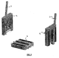
Figure 3 is a perspective view similar toFigure 2 , but with the external parts of the footrest assembly positioned in an aside pivoted position; -
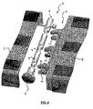
Figure 4 is a view in detail of first and second connecting means, in the splitted position of the footrest assembly ofFigure 1 ; -
Figure 5 is a view similar toFigure 4 , but in the partially assembled position of the footrest assembly ofFigure 1 ; -
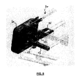
Figure 6 is a view similar toFigure 4 , but in the assembled position of the footrest assembly ofFigure 1 ; -
Figure 7 is a perspective view of a calfrest used in the wheelchair of the present invention; -
Figure 8 is a perspective view similar toFigure 7 but with the calfrest positioned in a completely folded up position. - In reference to
Figures 1 to 3 , a footrest assembly conform to the present invention is shown. - The
footrest assembly 10 comprises twoexternal parts 1 and amiddle part 2. Eachexternal part 1 constitutes a conventional footrest of a wheelchair and is pivotally connected to the frame part 3 of a legrest, respectively positioned at the left and at the right side of the wheelchair frame. Themiddle part 2 constitutes an extension plate that is detachably connected to saidexternal parts 1 at its two lateral ends 5. The connection between saidexternal parts 1 and saidmiddle part 2 can be achieved for instance by positioning a first connecting means at the ends 4 of saidexternal parts 1 that are in contact with the lateral ends 5 of saidmiddle part 2, hereinafter referred to as connecting ends 4, said first connecting means being configured so as to interact with second connecting means positioned at each lateral end 5 of saidmiddle part 2. Such first and second connecting means will be described afterwards in relation toFigure 4 to 6 . However, it is evident that such a connection could also be achieved by only using first connecting means. For instance, such first connecting means could consist in at least one clip or claw positioned on the border of the connecting ends 4 and configured to pinch an external wall of themiddle part 2, positioned at each lateral end of saidmiddle part 2. In order to detach themiddle part 2 from the rest of thefootrest assembly 10, eachexternal part 1 will be advantageously provided with disconnectingmeans 6. In an other embodiment of the present invention, such disconnecting means could also be integrated to themiddle part 2. However, such disconnecting means are only optional and specific embodiments of the present invention could also be proposed without disconnecting means. In this case, the user must act directly on the first connecting means to detach themiddle part 2 from theexternal parts 1. - Thus, when an assistant decides to transfer a user from the wheelchair of the present invention, he begins to remove the
middle part 2 from the rest of the footrest assembly 10 (seeFigure 2 ). For doing this, he must firstly activate the disconnectingmeans 6 positioned on one external face of theexternal parts 1 so that the interaction between first connecting means and second connecting means is stopped, leading to the disconnection between saidexternal parts 1 and saidmiddle part 2. However, in this position, mechanical pieces of themiddle part 2 or of theexternal parts 1 can still prevent the removal of saidmiddle part 2. So, to completely removesaid middle part 2, it is necessary to push aside the frame part 3 of each legrest so that eachexternal part 1 can be separed from themiddle part 2. Thus, when themiddle part 2 is removed, a free space is created between theexternal parts 1, said space being sufficient for receiving at least one foot of the user. By successively putting the user's feet outside of the wheelchair and, optionally, pivoting sideways theexternal parts 1, it will be easier for the assistant to transfer the user from the wheelchair. - In reference to
Figure 4 , one can see oneexternal part 1 and themiddle part 2 in the splitted position of the footrest assembly.Figure 4 shows that said first connecting means comprise arod 7 extending along the connecting end 4 of saidexternal part 1, saidrod 7 having series of first tubular segments 8 separated by series of second tubular segments 9, the diameter of said first tubular segments 8 being lower than the diameter of said second tubular segments 9, and said second connecting means comprise series of connecting elements 11 spaced apart along the lateral ends 5 of themiddle part 2, said connecting elements 11 having aslot 12 formed inside, saidslot 12 comprising a first portion 12' in which only said first tubular segments 8 can be introduced and asecond portion 12" having a tubular form and approximately the same diameter than said second tubular segments 9. Said first portion 12' can be formed by two parallel plane walls separated by a distance slightly higher than the diameter of said first tubular segments 8 but lower than the diameter of said second tubular segments 9. Therefore, in the partially assembled position of the footrest assembly 10 (seeFigure 5 ), said first tubular segments 8 are firstly positioned in front of said connecting elements 11 and introduced inside thesecond portion 12" of theslot 12 through said first portion 12'. To finalize the assembly of saidmiddle part 2 to saidexternal part 1, it is necessary to move therod 7 in a direction parallel to its axis so as to position said second tubular segments 9 in front of said said connecting elements 11, said second tubular segments 9 being then introduced inside thesecond portion 12" of saidslot 12. Accordingly, saidrod 7 is provided with a oblong slot 14 extending in a direction parallel to its axis, inside which is inserted a pin 13 fixedly connected to theexternal part 1, so that saidrod 7 is slidably connected to saidexternal part 1. In this assembled position (seeFigure 6 ), it is not possible to disconnect themiddle part 2 from theexternal part 1. - To disconnect said
middle part 2 from saidexternal part 1, thefootrest assembly 10 is provided with a disconnecting means, said disconnecting means being positioned on an external place that can be reached easily by the user and being configured to act on saidrod 7 so as to disconnect saidmiddle part 2 from saidexternal part 1. Such a disconnecting means can consist in abutton 6 fixedly connected at one end of saidrod 7. Saidbutton 6 can be pushed by the user in the assembled position ofFigure 6 so as to move saidrod 7 parallel to its axis. Thus, therod 7 reaches the partially assembled position ofFigure 5 . Afterwards, the user can move aside saidexternal part 1 from saidmiddle part 2, reaching the splitted position ofFigure 4 . Aspring 15 positioned at one end of saidrod 7, in contact with the internal face of saidbutton 6, is configured to act on saidbutton 6 so that saidrod 7 returns continuously to its position ofFigure 6 . - The wheelchair of the present invention comprises also a
calfrest 20 connected to the wheelchair frame 30 (seeFigure 7 ). In the conventional wheelchairs, the calfrest is generally attached to the legrest frame. However, in the specific case of a wheelchair for heavy persons, this calfrest is too heavy and too large to connect it on the legrest. Furthermore, this big calfrest can be embarrassing during the transfer of the user from the wheelchair. The solution of the present invention consists in movably connecting this calfrest to the wheelchair frame so as to provide a completely folded up position of the calfrest in which it does not interfere with the legs of the user. To get this result, thecalfrest 20 is slideably connected to a first support 21, said first support 21 being slideably connected to asecond support 22 fixedly connected to thewheelchair frame 30. Accordingly, a connectingbar 23 fixedly connected to the back 20' of saidcalfrest 20 is slidably connected, for instance by using a screw, to a first connectingpart 24 of said first support 21 so that the position of said back 20' with regard to said first support 21 can be modified. In addition, a second connectingpart 25 of said first support 21 is slideably connected to a first connectingpart 26 of saidsecond support 22 so that the angular position of said back 20' with regard to thewheelchair frame 30 can be modified. Said second connectingpart 25 comprises an arcuated plate fixedly connected at one end to the first connectingpart 24 and defining a guide path inside which is slideaby connected the first connectingpart 26, for instance by using a screw, said first connectingpart 26 having a complementary form to said guide path. A second connectingpart 27 of saidsecond support 22 is fixedly connected at one end to said first connectingpart 26 and fixedly connected at its other end to thewheelchair frame 30. Therefore, in the work position ofFigure 7 , the first connectingpart 24 being positioned at the free end of the connectingbar 23, the back 20' is distant from the first support 21 and, the first connectingpart 26 being positioned partially outside of the guide path defined by the second connectingpart 25, said back 20' is tilted with regard to the vertical. In the rest position ofFigure 8 , the first connectingpart 24 being positioned at the other end of the connectingbar 23, said back 20' is close to said first support 21 and, the first connectingpart 26 being positioned completely inside of the guide path defined by the second connectingpart 25, said back 20' is aligned with the vertical.
Claims (10)
- A wheelchair provided with two legrests, each legrest comprising a frame part (3) and, connected thereto, a footrest (1),
characterized in that each footrest (1) comprises at one of their ends (4), namely connecting end, first connecting means (7) so as to detachably connect an extension plate (2) between said connecting ends (4). - A wheelchair according to claim 1, wherein each footrest (1) comprises disconnecting means (6) configured to act on said first connecting means (7) so as to disconnect the extension plate (2) from said connecting ends (4).
- A wheelchair according to any one of the preceding claims,
wherein the extension plate (2) comprises second connecting means (11) at each of its lateral ends (5) configured to interact with said first connecting means (7) so as to be detachably connected to the footrests (1). - A wheelchair according to claim 3, wherein said first connecting means comprise a rod (7) extending along the connecting end (4) of each footrest (1), said rod (7) having series of first tubular segments (8) separated by series of second tubular segments (9), the diameter of said first tubular segments (8) being lower than the diameter of said second tubular segments (9), and said second connecting means comprise series of connecting elements (11) spaced apart along the lateral ends (5) of the extension plate (2), said connecting elements (11) having a slot (12) formed inside, said slot (12) comprising a first portion (12') in which only said first tubular segments (8) can be introduced and a second portion (12") having a tubular form and approximately the same diameter than said second tubular segments (9).
- A wheelchair according to claim 4, wherein disconnecting means comprise a button (6) fixedly connected to said rod (7), said button (6) acting on said rod (7) so as to move said first tubular segments (8) in front of said connecting elements (11).
- A wheelchair according to claim 5, wherein a spring (15) positioned inside each footrest (1) acts on said rod (7) so as to move said second tubular segments (9) in front of said connecting elements (11).
- A whhelchair according to any one of the preceding claim, wherein each footrest (1) is pivotally connected to said frame part (3).
- A wheelchair according to any one of the preceding claims, wherein it comprises a wheelchair frame (30) and, connected at each side thereof, a calfrest (20).
- A wheelchair according to claim 8, wherein said calfrest (20) is movably connected to said wheelchair frame (30).
- A wheelchair according to claim 9, wherein said calfrest (20) is detachably connected to said wheelchair frame (30).
Priority Applications (1)
| Application Number | Priority Date | Filing Date | Title |
|---|---|---|---|
| EP10765524.3A EP2482782B1 (en) | 2009-09-30 | 2010-09-29 | Wheelchair for heavy persons |
Applications Claiming Priority (3)
| Application Number | Priority Date | Filing Date | Title |
|---|---|---|---|
| EP09171772A EP2305197A1 (en) | 2009-09-30 | 2009-09-30 | Wheelchair for heavy persons |
| EP10765524.3A EP2482782B1 (en) | 2009-09-30 | 2010-09-29 | Wheelchair for heavy persons |
| PCT/IB2010/054398 WO2011039714A1 (en) | 2009-09-30 | 2010-09-29 | Wheelchair for heavy persons |
Publications (2)
| Publication Number | Publication Date |
|---|---|
| EP2482782A1 EP2482782A1 (en) | 2012-08-08 |
| EP2482782B1 true EP2482782B1 (en) | 2014-07-23 |
Family
ID=41581180
Family Applications (2)
| Application Number | Title | Priority Date | Filing Date |
|---|---|---|---|
| EP09171772A Withdrawn EP2305197A1 (en) | 2009-09-30 | 2009-09-30 | Wheelchair for heavy persons |
| EP10765524.3A Active EP2482782B1 (en) | 2009-09-30 | 2010-09-29 | Wheelchair for heavy persons |
Family Applications Before (1)
| Application Number | Title | Priority Date | Filing Date |
|---|---|---|---|
| EP09171772A Withdrawn EP2305197A1 (en) | 2009-09-30 | 2009-09-30 | Wheelchair for heavy persons |
Country Status (4)
| Country | Link |
|---|---|
| EP (2) | EP2305197A1 (en) |
| DK (1) | DK2482782T3 (en) |
| ES (1) | ES2509920T3 (en) |
| WO (1) | WO2011039714A1 (en) |
Families Citing this family (2)
| Publication number | Priority date | Publication date | Assignee | Title |
|---|---|---|---|---|
| JP6717642B2 (en) * | 2016-04-01 | 2020-07-01 | 株式会社スワニー | wheelchair |
| CN106726213B (en) * | 2017-03-13 | 2018-06-22 | 安维车件(厦门)有限公司 | It is a kind of to two foot pedals to lock foldable on lock construction and wheelchair |
Family Cites Families (3)
| Publication number | Priority date | Publication date | Assignee | Title |
|---|---|---|---|---|
| US5186480A (en) * | 1990-12-05 | 1993-02-16 | Morgan Technology, Inc. | Lightweight transportable wheelchair |
| AU2004279437B2 (en) * | 2003-10-08 | 2010-11-11 | Turbo Wheelchair Co., Inc. | Wheelchair designs and related enhancements |
| US20080116732A1 (en) * | 2006-11-20 | 2008-05-22 | Herschel Hiatt | Device for use with a wheelchair |
-
2009
- 2009-09-30 EP EP09171772A patent/EP2305197A1/en not_active Withdrawn
-
2010
- 2010-09-29 ES ES10765524.3T patent/ES2509920T3/en active Active
- 2010-09-29 EP EP10765524.3A patent/EP2482782B1/en active Active
- 2010-09-29 DK DK10765524.3T patent/DK2482782T3/en active
- 2010-09-29 WO PCT/IB2010/054398 patent/WO2011039714A1/en not_active Ceased
Also Published As
| Publication number | Publication date |
|---|---|
| WO2011039714A1 (en) | 2011-04-07 |
| EP2305197A1 (en) | 2011-04-06 |
| DK2482782T3 (en) | 2014-10-27 |
| EP2482782A1 (en) | 2012-08-08 |
| ES2509920T3 (en) | 2014-10-20 |
Similar Documents
| Publication | Publication Date | Title |
|---|---|---|
| US7673888B2 (en) | Combined wheelchair, walker, and sitting chair | |
| TWI649079B (en) | A mobile support assembly (1) | |
| CN114190809A (en) | toilet frame | |
| US9113757B2 (en) | Toilet and support bars for the disabled | |
| EP2305197A1 (en) | Wheelchair for heavy persons | |
| JP3226653U (en) | Transfer assistance chair | |
| US8484770B2 (en) | Toilet for the disabled | |
| TWI649076B (en) | A mobile support assembly (2) | |
| JP2005007184A (en) | Wheelchair equipped with improved leg holding means | |
| KR200465717Y1 (en) | Wheel chair capable of adjusting angles of leg frame therof | |
| EP1791509A1 (en) | Apparatus for assisting a person between a substantially standing posture and a seated posture | |
| US20210251828A1 (en) | Bariatric wheelchair | |
| KR20230086002A (en) | Patient lift | |
| JP4289957B2 (en) | Shower folding chair | |
| JP2013074954A (en) | Elevatable collapsable footrest device and wheelchair using the same | |
| KR20140137933A (en) | Separable wheelchair for the old and the infirm and handicapped and public | |
| CN219049199U (en) | Walking chair | |
| JP2008246197A (en) | Wheelchair with shift assisting function | |
| JPH11197189A (en) | Wheelchair | |
| KR101781576B1 (en) | Wheelchair | |
| JP5064850B2 (en) | Chair | |
| KR200268418Y1 (en) | Wheelchair | |
| KR200398836Y1 (en) | Wheel Chair With Fold able arm-frames | |
| JP6877020B2 (en) | wheelchair | |
| JP2005103248A (en) | Body frame for wheelchair |
Legal Events
| Date | Code | Title | Description |
|---|---|---|---|
| PUAI | Public reference made under article 153(3) epc to a published international application that has entered the european phase |
Free format text: ORIGINAL CODE: 0009012 |
|
| 17P | Request for examination filed |
Effective date: 20120418 |
|
| AK | Designated contracting states |
Kind code of ref document: A1 Designated state(s): AL AT BE BG CH CY CZ DE DK EE ES FI FR GB GR HR HU IE IS IT LI LT LU LV MC MK MT NL NO PL PT RO SE SI SK SM TR |
|
| DAX | Request for extension of the european patent (deleted) | ||
| GRAP | Despatch of communication of intention to grant a patent |
Free format text: ORIGINAL CODE: EPIDOSNIGR1 |
|
| INTG | Intention to grant announced |
Effective date: 20140107 |
|
| GRAS | Grant fee paid |
Free format text: ORIGINAL CODE: EPIDOSNIGR3 |
|
| GRAA | (expected) grant |
Free format text: ORIGINAL CODE: 0009210 |
|
| AK | Designated contracting states |
Kind code of ref document: B1 Designated state(s): AL AT BE BG CH CY CZ DE DK EE ES FI FR GB GR HR HU IE IS IT LI LT LU LV MC MK MT NL NO PL PT RO SE SI SK SM TR |
|
| REG | Reference to a national code |
Ref country code: GB Ref legal event code: FG4D |
|
| REG | Reference to a national code |
Ref country code: CH Ref legal event code: EP |
|
| REG | Reference to a national code |
Ref country code: IE Ref legal event code: FG4D |
|
| REG | Reference to a national code |
Ref country code: AT Ref legal event code: REF Ref document number: 678421 Country of ref document: AT Kind code of ref document: T Effective date: 20140815 |
|
| REG | Reference to a national code |
Ref country code: DE Ref legal event code: R096 Ref document number: 602010017748 Country of ref document: DE Effective date: 20140904 |
|
| REG | Reference to a national code |
Ref country code: CH Ref legal event code: NV Representative=s name: ABREMA AGENCE BREVET ET MARQUES, GANGUILLET, CH |
|
| REG | Reference to a national code |
Ref country code: ES Ref legal event code: FG2A Ref document number: 2509920 Country of ref document: ES Kind code of ref document: T3 Effective date: 20141020 |
|
| REG | Reference to a national code |
Ref country code: DK Ref legal event code: T3 Effective date: 20141023 |
|
| REG | Reference to a national code |
Ref country code: SE Ref legal event code: TRGR |
|
| REG | Reference to a national code |
Ref country code: NL Ref legal event code: T3 |
|
| REG | Reference to a national code |
Ref country code: NO Ref legal event code: T2 Effective date: 20140723 |
|
| REG | Reference to a national code |
Ref country code: AT Ref legal event code: MK05 Ref document number: 678421 Country of ref document: AT Kind code of ref document: T Effective date: 20140723 |
|
| REG | Reference to a national code |
Ref country code: LT Ref legal event code: MG4D |
|
| PG25 | Lapsed in a contracting state [announced via postgrant information from national office to epo] |
Ref country code: GR Free format text: LAPSE BECAUSE OF FAILURE TO SUBMIT A TRANSLATION OF THE DESCRIPTION OR TO PAY THE FEE WITHIN THE PRESCRIBED TIME-LIMIT Effective date: 20141024 Ref country code: PT Free format text: LAPSE BECAUSE OF FAILURE TO SUBMIT A TRANSLATION OF THE DESCRIPTION OR TO PAY THE FEE WITHIN THE PRESCRIBED TIME-LIMIT Effective date: 20141124 Ref country code: FI Free format text: LAPSE BECAUSE OF FAILURE TO SUBMIT A TRANSLATION OF THE DESCRIPTION OR TO PAY THE FEE WITHIN THE PRESCRIBED TIME-LIMIT Effective date: 20140723 Ref country code: BG Free format text: LAPSE BECAUSE OF FAILURE TO SUBMIT A TRANSLATION OF THE DESCRIPTION OR TO PAY THE FEE WITHIN THE PRESCRIBED TIME-LIMIT Effective date: 20141023 Ref country code: LT Free format text: LAPSE BECAUSE OF FAILURE TO SUBMIT A TRANSLATION OF THE DESCRIPTION OR TO PAY THE FEE WITHIN THE PRESCRIBED TIME-LIMIT Effective date: 20140723 |
|
| PG25 | Lapsed in a contracting state [announced via postgrant information from national office to epo] |
Ref country code: PL Free format text: LAPSE BECAUSE OF FAILURE TO SUBMIT A TRANSLATION OF THE DESCRIPTION OR TO PAY THE FEE WITHIN THE PRESCRIBED TIME-LIMIT Effective date: 20140723 Ref country code: LV Free format text: LAPSE BECAUSE OF FAILURE TO SUBMIT A TRANSLATION OF THE DESCRIPTION OR TO PAY THE FEE WITHIN THE PRESCRIBED TIME-LIMIT Effective date: 20140723 Ref country code: CY Free format text: LAPSE BECAUSE OF FAILURE TO SUBMIT A TRANSLATION OF THE DESCRIPTION OR TO PAY THE FEE WITHIN THE PRESCRIBED TIME-LIMIT Effective date: 20140723 Ref country code: AT Free format text: LAPSE BECAUSE OF FAILURE TO SUBMIT A TRANSLATION OF THE DESCRIPTION OR TO PAY THE FEE WITHIN THE PRESCRIBED TIME-LIMIT Effective date: 20140723 Ref country code: IS Free format text: LAPSE BECAUSE OF FAILURE TO SUBMIT A TRANSLATION OF THE DESCRIPTION OR TO PAY THE FEE WITHIN THE PRESCRIBED TIME-LIMIT Effective date: 20141123 Ref country code: HR Free format text: LAPSE BECAUSE OF FAILURE TO SUBMIT A TRANSLATION OF THE DESCRIPTION OR TO PAY THE FEE WITHIN THE PRESCRIBED TIME-LIMIT Effective date: 20140723 |
|
| REG | Reference to a national code |
Ref country code: DE Ref legal event code: R097 Ref document number: 602010017748 Country of ref document: DE |
|
| PG25 | Lapsed in a contracting state [announced via postgrant information from national office to epo] |
Ref country code: LU Free format text: LAPSE BECAUSE OF FAILURE TO SUBMIT A TRANSLATION OF THE DESCRIPTION OR TO PAY THE FEE WITHIN THE PRESCRIBED TIME-LIMIT Effective date: 20140929 Ref country code: MC Free format text: LAPSE BECAUSE OF FAILURE TO SUBMIT A TRANSLATION OF THE DESCRIPTION OR TO PAY THE FEE WITHIN THE PRESCRIBED TIME-LIMIT Effective date: 20140723 Ref country code: EE Free format text: LAPSE BECAUSE OF FAILURE TO SUBMIT A TRANSLATION OF THE DESCRIPTION OR TO PAY THE FEE WITHIN THE PRESCRIBED TIME-LIMIT Effective date: 20140723 Ref country code: CZ Free format text: LAPSE BECAUSE OF FAILURE TO SUBMIT A TRANSLATION OF THE DESCRIPTION OR TO PAY THE FEE WITHIN THE PRESCRIBED TIME-LIMIT Effective date: 20140723 Ref country code: SK Free format text: LAPSE BECAUSE OF FAILURE TO SUBMIT A TRANSLATION OF THE DESCRIPTION OR TO PAY THE FEE WITHIN THE PRESCRIBED TIME-LIMIT Effective date: 20140723 Ref country code: RO Free format text: LAPSE BECAUSE OF FAILURE TO SUBMIT A TRANSLATION OF THE DESCRIPTION OR TO PAY THE FEE WITHIN THE PRESCRIBED TIME-LIMIT Effective date: 20140723 |
|
| REG | Reference to a national code |
Ref country code: CH Ref legal event code: PL |
|
| PLBE | No opposition filed within time limit |
Free format text: ORIGINAL CODE: 0009261 |
|
| STAA | Information on the status of an ep patent application or granted ep patent |
Free format text: STATUS: NO OPPOSITION FILED WITHIN TIME LIMIT |
|
| PG25 | Lapsed in a contracting state [announced via postgrant information from national office to epo] |
Ref country code: BE Free format text: LAPSE BECAUSE OF NON-PAYMENT OF DUE FEES Effective date: 20140930 |
|
| 26N | No opposition filed |
Effective date: 20150424 |
|
| REG | Reference to a national code |
Ref country code: IE Ref legal event code: MM4A |
|
| PG25 | Lapsed in a contracting state [announced via postgrant information from national office to epo] |
Ref country code: CH Free format text: LAPSE BECAUSE OF NON-PAYMENT OF DUE FEES Effective date: 20140930 Ref country code: LI Free format text: LAPSE BECAUSE OF NON-PAYMENT OF DUE FEES Effective date: 20140930 |
|
| PG25 | Lapsed in a contracting state [announced via postgrant information from national office to epo] |
Ref country code: IE Free format text: LAPSE BECAUSE OF NON-PAYMENT OF DUE FEES Effective date: 20140929 |
|
| REG | Reference to a national code |
Ref country code: FR Ref legal event code: PLFP Year of fee payment: 6 |
|
| PG25 | Lapsed in a contracting state [announced via postgrant information from national office to epo] |
Ref country code: SI Free format text: LAPSE BECAUSE OF FAILURE TO SUBMIT A TRANSLATION OF THE DESCRIPTION OR TO PAY THE FEE WITHIN THE PRESCRIBED TIME-LIMIT Effective date: 20140723 |
|
| PG25 | Lapsed in a contracting state [announced via postgrant information from national office to epo] |
Ref country code: SM Free format text: LAPSE BECAUSE OF FAILURE TO SUBMIT A TRANSLATION OF THE DESCRIPTION OR TO PAY THE FEE WITHIN THE PRESCRIBED TIME-LIMIT Effective date: 20140723 |
|
| PG25 | Lapsed in a contracting state [announced via postgrant information from national office to epo] |
Ref country code: MT Free format text: LAPSE BECAUSE OF FAILURE TO SUBMIT A TRANSLATION OF THE DESCRIPTION OR TO PAY THE FEE WITHIN THE PRESCRIBED TIME-LIMIT Effective date: 20140723 |
|
| PG25 | Lapsed in a contracting state [announced via postgrant information from national office to epo] |
Ref country code: BE Free format text: LAPSE BECAUSE OF FAILURE TO SUBMIT A TRANSLATION OF THE DESCRIPTION OR TO PAY THE FEE WITHIN THE PRESCRIBED TIME-LIMIT Effective date: 20140723 Ref country code: HU Free format text: LAPSE BECAUSE OF FAILURE TO SUBMIT A TRANSLATION OF THE DESCRIPTION OR TO PAY THE FEE WITHIN THE PRESCRIBED TIME-LIMIT; INVALID AB INITIO Effective date: 20100929 Ref country code: TR Free format text: LAPSE BECAUSE OF FAILURE TO SUBMIT A TRANSLATION OF THE DESCRIPTION OR TO PAY THE FEE WITHIN THE PRESCRIBED TIME-LIMIT Effective date: 20140723 |
|
| REG | Reference to a national code |
Ref country code: FR Ref legal event code: PLFP Year of fee payment: 7 |
|
| REG | Reference to a national code |
Ref country code: FR Ref legal event code: PLFP Year of fee payment: 8 |
|
| PG25 | Lapsed in a contracting state [announced via postgrant information from national office to epo] |
Ref country code: MK Free format text: LAPSE BECAUSE OF FAILURE TO SUBMIT A TRANSLATION OF THE DESCRIPTION OR TO PAY THE FEE WITHIN THE PRESCRIBED TIME-LIMIT Effective date: 20140723 |
|
| REG | Reference to a national code |
Ref country code: FR Ref legal event code: PLFP Year of fee payment: 9 |
|
| PG25 | Lapsed in a contracting state [announced via postgrant information from national office to epo] |
Ref country code: AL Free format text: LAPSE BECAUSE OF FAILURE TO SUBMIT A TRANSLATION OF THE DESCRIPTION OR TO PAY THE FEE WITHIN THE PRESCRIBED TIME-LIMIT Effective date: 20140723 |
|
| REG | Reference to a national code |
Ref country code: DE Ref legal event code: R082 Ref document number: 602010017748 Country of ref document: DE Representative=s name: KARAKATSANIS, GEORGIOS, DR., DE |
|
| PGFP | Annual fee paid to national office [announced via postgrant information from national office to epo] |
Ref country code: DK Payment date: 20250929 Year of fee payment: 16 |
|
| PGFP | Annual fee paid to national office [announced via postgrant information from national office to epo] |
Ref country code: IT Payment date: 20250929 Year of fee payment: 16 Ref country code: NL Payment date: 20250929 Year of fee payment: 16 |
|
| PGFP | Annual fee paid to national office [announced via postgrant information from national office to epo] |
Ref country code: GB Payment date: 20250929 Year of fee payment: 16 |
|
| PGFP | Annual fee paid to national office [announced via postgrant information from national office to epo] |
Ref country code: FR Payment date: 20250929 Year of fee payment: 16 |
|
| PGFP | Annual fee paid to national office [announced via postgrant information from national office to epo] |
Ref country code: SE Payment date: 20250929 Year of fee payment: 16 |
|
| PGFP | Annual fee paid to national office [announced via postgrant information from national office to epo] |
Ref country code: DE Payment date: 20250929 Year of fee payment: 16 |
|
| PGFP | Annual fee paid to national office [announced via postgrant information from national office to epo] |
Ref country code: NO Payment date: 20251001 Year of fee payment: 16 |
|
| PGFP | Annual fee paid to national office [announced via postgrant information from national office to epo] |
Ref country code: ES Payment date: 20251028 Year of fee payment: 16 |