EP2482722B1 - Exercise devices with force sensors - Google Patents
Exercise devices with force sensors Download PDFInfo
- Publication number
- EP2482722B1 EP2482722B1 EP10821332.3A EP10821332A EP2482722B1 EP 2482722 B1 EP2482722 B1 EP 2482722B1 EP 10821332 A EP10821332 A EP 10821332A EP 2482722 B1 EP2482722 B1 EP 2482722B1
- Authority
- EP
- European Patent Office
- Prior art keywords
- socket
- neck
- sensor body
- exercise device
- passage
- Prior art date
- Legal status (The legal status is an assumption and is not a legal conclusion. Google has not performed a legal analysis and makes no representation as to the accuracy of the status listed.)
- Not-in-force
Links
- 238000004891 communication Methods 0.000 description 7
- 230000000694 effects Effects 0.000 description 7
- 230000033001 locomotion Effects 0.000 description 5
- 238000012544 monitoring process Methods 0.000 description 5
- 238000005259 measurement Methods 0.000 description 4
- 210000003423 ankle Anatomy 0.000 description 3
- 230000000295 complement effect Effects 0.000 description 3
- 230000014759 maintenance of location Effects 0.000 description 3
- 238000012545 processing Methods 0.000 description 3
- 238000012552 review Methods 0.000 description 3
- 230000000007 visual effect Effects 0.000 description 3
- 238000004458 analytical method Methods 0.000 description 2
- 238000005452 bending Methods 0.000 description 2
- 230000005540 biological transmission Effects 0.000 description 2
- 230000008859 change Effects 0.000 description 2
- 230000006835 compression Effects 0.000 description 2
- 238000007906 compression Methods 0.000 description 2
- 230000008878 coupling Effects 0.000 description 2
- 238000010168 coupling process Methods 0.000 description 2
- 238000005859 coupling reaction Methods 0.000 description 2
- 238000013481 data capture Methods 0.000 description 2
- 230000007423 decrease Effects 0.000 description 2
- 230000005672 electromagnetic field Effects 0.000 description 2
- 210000003414 extremity Anatomy 0.000 description 2
- 230000006870 function Effects 0.000 description 2
- 238000009434 installation Methods 0.000 description 2
- 238000012986 modification Methods 0.000 description 2
- 230000004048 modification Effects 0.000 description 2
- 210000000707 wrist Anatomy 0.000 description 2
- 229910000831 Steel Inorganic materials 0.000 description 1
- 230000004888 barrier function Effects 0.000 description 1
- 238000004364 calculation method Methods 0.000 description 1
- 239000013078 crystal Substances 0.000 description 1
- 230000001186 cumulative effect Effects 0.000 description 1
- 238000013500 data storage Methods 0.000 description 1
- 230000001419 dependent effect Effects 0.000 description 1
- 230000004907 flux Effects 0.000 description 1
- 210000002683 foot Anatomy 0.000 description 1
- 230000001939 inductive effect Effects 0.000 description 1
- 230000007774 longterm Effects 0.000 description 1
- 239000000463 material Substances 0.000 description 1
- 238000000034 method Methods 0.000 description 1
- 210000003205 muscle Anatomy 0.000 description 1
- 230000003287 optical effect Effects 0.000 description 1
- 238000003825 pressing Methods 0.000 description 1
- 230000001020 rhythmical effect Effects 0.000 description 1
- 230000011664 signaling Effects 0.000 description 1
- 239000010959 steel Substances 0.000 description 1
- 239000000126 substance Substances 0.000 description 1
- 230000002459 sustained effect Effects 0.000 description 1
- 238000003466 welding Methods 0.000 description 1
Images



Classifications
-
- A—HUMAN NECESSITIES
- A61—MEDICAL OR VETERINARY SCIENCE; HYGIENE
- A61B—DIAGNOSIS; SURGERY; IDENTIFICATION
- A61B5/00—Measuring for diagnostic purposes; Identification of persons
- A61B5/22—Ergometry; Measuring muscular strength or the force of a muscular blow
- A61B5/224—Measuring muscular strength
-
- A—HUMAN NECESSITIES
- A63—SPORTS; GAMES; AMUSEMENTS
- A63B—APPARATUS FOR PHYSICAL TRAINING, GYMNASTICS, SWIMMING, CLIMBING, OR FENCING; BALL GAMES; TRAINING EQUIPMENT
- A63B21/00—Exercising apparatus for developing or strengthening the muscles or joints of the body by working against a counterforce, with or without measuring devices
- A63B21/005—Exercising apparatus for developing or strengthening the muscles or joints of the body by working against a counterforce, with or without measuring devices using electromagnetic or electric force-resisters
- A63B21/0053—Exercising apparatus for developing or strengthening the muscles or joints of the body by working against a counterforce, with or without measuring devices using electromagnetic or electric force-resisters using alternators or dynamos
- A63B21/0055—Exercising apparatus for developing or strengthening the muscles or joints of the body by working against a counterforce, with or without measuring devices using electromagnetic or electric force-resisters using alternators or dynamos the produced electric power used as a source for other equipment, e.g. for TVs
-
- A—HUMAN NECESSITIES
- A63—SPORTS; GAMES; AMUSEMENTS
- A63B—APPARATUS FOR PHYSICAL TRAINING, GYMNASTICS, SWIMMING, CLIMBING, OR FENCING; BALL GAMES; TRAINING EQUIPMENT
- A63B21/00—Exercising apparatus for developing or strengthening the muscles or joints of the body by working against a counterforce, with or without measuring devices
- A63B21/02—Exercising apparatus for developing or strengthening the muscles or joints of the body by working against a counterforce, with or without measuring devices using resilient force-resisters
- A63B21/055—Exercising apparatus for developing or strengthening the muscles or joints of the body by working against a counterforce, with or without measuring devices using resilient force-resisters extension element type
- A63B21/0552—Elastic ropes or bands
-
- A—HUMAN NECESSITIES
- A63—SPORTS; GAMES; AMUSEMENTS
- A63B—APPARATUS FOR PHYSICAL TRAINING, GYMNASTICS, SWIMMING, CLIMBING, OR FENCING; BALL GAMES; TRAINING EQUIPMENT
- A63B21/00—Exercising apparatus for developing or strengthening the muscles or joints of the body by working against a counterforce, with or without measuring devices
- A63B21/40—Interfaces with the user related to strength training; Details thereof
- A63B21/4001—Arrangements for attaching the exercising apparatus to the user's body, e.g. belts, shoes or gloves specially adapted therefor
- A63B21/4017—Arrangements for attaching the exercising apparatus to the user's body, e.g. belts, shoes or gloves specially adapted therefor to the upper limbs
-
- A—HUMAN NECESSITIES
- A63—SPORTS; GAMES; AMUSEMENTS
- A63B—APPARATUS FOR PHYSICAL TRAINING, GYMNASTICS, SWIMMING, CLIMBING, OR FENCING; BALL GAMES; TRAINING EQUIPMENT
- A63B21/00—Exercising apparatus for developing or strengthening the muscles or joints of the body by working against a counterforce, with or without measuring devices
- A63B21/40—Interfaces with the user related to strength training; Details thereof
- A63B21/4001—Arrangements for attaching the exercising apparatus to the user's body, e.g. belts, shoes or gloves specially adapted therefor
- A63B21/4017—Arrangements for attaching the exercising apparatus to the user's body, e.g. belts, shoes or gloves specially adapted therefor to the upper limbs
- A63B21/4021—Arrangements for attaching the exercising apparatus to the user's body, e.g. belts, shoes or gloves specially adapted therefor to the upper limbs to the wrist
-
- A—HUMAN NECESSITIES
- A63—SPORTS; GAMES; AMUSEMENTS
- A63B—APPARATUS FOR PHYSICAL TRAINING, GYMNASTICS, SWIMMING, CLIMBING, OR FENCING; BALL GAMES; TRAINING EQUIPMENT
- A63B21/00—Exercising apparatus for developing or strengthening the muscles or joints of the body by working against a counterforce, with or without measuring devices
- A63B21/40—Interfaces with the user related to strength training; Details thereof
- A63B21/4027—Specific exercise interfaces
- A63B21/4033—Handles, pedals, bars or platforms
- A63B21/4035—Handles, pedals, bars or platforms for operation by hand
-
- A—HUMAN NECESSITIES
- A63—SPORTS; GAMES; AMUSEMENTS
- A63B—APPARATUS FOR PHYSICAL TRAINING, GYMNASTICS, SWIMMING, CLIMBING, OR FENCING; BALL GAMES; TRAINING EQUIPMENT
- A63B24/00—Electric or electronic controls for exercising apparatus of preceding groups; Controlling or monitoring of exercises, sportive games, training or athletic performances
- A63B24/0062—Monitoring athletic performances, e.g. for determining the work of a user on an exercise apparatus, the completed jogging or cycling distance
-
- A—HUMAN NECESSITIES
- A61—MEDICAL OR VETERINARY SCIENCE; HYGIENE
- A61B—DIAGNOSIS; SURGERY; IDENTIFICATION
- A61B5/00—Measuring for diagnostic purposes; Identification of persons
- A61B5/0002—Remote monitoring of patients using telemetry, e.g. transmission of vital signals via a communication network
-
- A—HUMAN NECESSITIES
- A63—SPORTS; GAMES; AMUSEMENTS
- A63B—APPARATUS FOR PHYSICAL TRAINING, GYMNASTICS, SWIMMING, CLIMBING, OR FENCING; BALL GAMES; TRAINING EQUIPMENT
- A63B71/00—Games or sports accessories not covered in groups A63B1/00 - A63B69/00
- A63B71/06—Indicating or scoring devices for games or players, or for other sports activities
- A63B71/0619—Displays, user interfaces and indicating devices, specially adapted for sport equipment, e.g. display mounted on treadmills
- A63B71/0622—Visual, audio or audio-visual systems for entertaining, instructing or motivating the user
- A63B2071/0625—Emitting sound, noise or music
-
- A—HUMAN NECESSITIES
- A63—SPORTS; GAMES; AMUSEMENTS
- A63B—APPARATUS FOR PHYSICAL TRAINING, GYMNASTICS, SWIMMING, CLIMBING, OR FENCING; BALL GAMES; TRAINING EQUIPMENT
- A63B71/00—Games or sports accessories not covered in groups A63B1/00 - A63B69/00
- A63B71/06—Indicating or scoring devices for games or players, or for other sports activities
- A63B71/0619—Displays, user interfaces and indicating devices, specially adapted for sport equipment, e.g. display mounted on treadmills
- A63B71/0622—Visual, audio or audio-visual systems for entertaining, instructing or motivating the user
- A63B2071/0625—Emitting sound, noise or music
- A63B2071/0627—Emitting sound, noise or music when used improperly, e.g. by giving a warning
-
- A—HUMAN NECESSITIES
- A63—SPORTS; GAMES; AMUSEMENTS
- A63B—APPARATUS FOR PHYSICAL TRAINING, GYMNASTICS, SWIMMING, CLIMBING, OR FENCING; BALL GAMES; TRAINING EQUIPMENT
- A63B71/00—Games or sports accessories not covered in groups A63B1/00 - A63B69/00
- A63B71/06—Indicating or scoring devices for games or players, or for other sports activities
- A63B71/0619—Displays, user interfaces and indicating devices, specially adapted for sport equipment, e.g. display mounted on treadmills
- A63B71/0622—Visual, audio or audio-visual systems for entertaining, instructing or motivating the user
- A63B2071/0625—Emitting sound, noise or music
- A63B2071/063—Spoken or verbal instructions
-
- A—HUMAN NECESSITIES
- A63—SPORTS; GAMES; AMUSEMENTS
- A63B—APPARATUS FOR PHYSICAL TRAINING, GYMNASTICS, SWIMMING, CLIMBING, OR FENCING; BALL GAMES; TRAINING EQUIPMENT
- A63B71/00—Games or sports accessories not covered in groups A63B1/00 - A63B69/00
- A63B71/06—Indicating or scoring devices for games or players, or for other sports activities
- A63B71/0619—Displays, user interfaces and indicating devices, specially adapted for sport equipment, e.g. display mounted on treadmills
- A63B2071/0655—Tactile feedback
-
- A—HUMAN NECESSITIES
- A63—SPORTS; GAMES; AMUSEMENTS
- A63B—APPARATUS FOR PHYSICAL TRAINING, GYMNASTICS, SWIMMING, CLIMBING, OR FENCING; BALL GAMES; TRAINING EQUIPMENT
- A63B21/00—Exercising apparatus for developing or strengthening the muscles or joints of the body by working against a counterforce, with or without measuring devices
- A63B21/02—Exercising apparatus for developing or strengthening the muscles or joints of the body by working against a counterforce, with or without measuring devices using resilient force-resisters
- A63B21/055—Exercising apparatus for developing or strengthening the muscles or joints of the body by working against a counterforce, with or without measuring devices using resilient force-resisters extension element type
- A63B21/0552—Elastic ropes or bands
- A63B21/0557—Details of attachments, e.g. clips or clamps
-
- A—HUMAN NECESSITIES
- A63—SPORTS; GAMES; AMUSEMENTS
- A63B—APPARATUS FOR PHYSICAL TRAINING, GYMNASTICS, SWIMMING, CLIMBING, OR FENCING; BALL GAMES; TRAINING EQUIPMENT
- A63B2220/00—Measuring of physical parameters relating to sporting activity
- A63B2220/50—Force related parameters
- A63B2220/51—Force
-
- A—HUMAN NECESSITIES
- A63—SPORTS; GAMES; AMUSEMENTS
- A63B—APPARATUS FOR PHYSICAL TRAINING, GYMNASTICS, SWIMMING, CLIMBING, OR FENCING; BALL GAMES; TRAINING EQUIPMENT
- A63B2225/00—Miscellaneous features of sport apparatus, devices or equipment
- A63B2225/20—Miscellaneous features of sport apparatus, devices or equipment with means for remote communication, e.g. internet or the like
-
- A—HUMAN NECESSITIES
- A63—SPORTS; GAMES; AMUSEMENTS
- A63B—APPARATUS FOR PHYSICAL TRAINING, GYMNASTICS, SWIMMING, CLIMBING, OR FENCING; BALL GAMES; TRAINING EQUIPMENT
- A63B2225/00—Miscellaneous features of sport apparatus, devices or equipment
- A63B2225/50—Wireless data transmission, e.g. by radio transmitters or telemetry
-
- A—HUMAN NECESSITIES
- A63—SPORTS; GAMES; AMUSEMENTS
- A63B—APPARATUS FOR PHYSICAL TRAINING, GYMNASTICS, SWIMMING, CLIMBING, OR FENCING; BALL GAMES; TRAINING EQUIPMENT
- A63B2230/00—Measuring physiological parameters of the user
- A63B2230/04—Measuring physiological parameters of the user heartbeat characteristics, e.g. ECG, blood pressure modulations
- A63B2230/06—Measuring physiological parameters of the user heartbeat characteristics, e.g. ECG, blood pressure modulations heartbeat rate only
-
- A—HUMAN NECESSITIES
- A63—SPORTS; GAMES; AMUSEMENTS
- A63B—APPARATUS FOR PHYSICAL TRAINING, GYMNASTICS, SWIMMING, CLIMBING, OR FENCING; BALL GAMES; TRAINING EQUIPMENT
- A63B2230/00—Measuring physiological parameters of the user
- A63B2230/75—Measuring physiological parameters of the user calorie expenditure
Definitions
- This document concerns an invention relating generally to exercise devices, and more specifically to exercise devices having force sensors for measuring, recording, and/or providing feedback regarding a user's activity.
- Force sensors are sometimes incorporated into exercise devices for monitoring user activity, e.g., the amount of force applied, the duration of exercise, etc.
- the force sensors can allow a user (or others, e.g., trainers or physical therapists) to quantify, record, and analyze the user's activity with greater ease and certainty.
- a sensor might precisely measure and record the amount of weight lifted during one exercise session, as well as the number of times it was lifted, the time over which it was lifted, etc., and the recorded data can then be compared to the results of a later exercise session to determine the user's progress.
- the force sensors are built directly into the structures of the exercise devices.
- the force sensing functionality suffers from many drawbacks present in the exercise devices themselves.
- the device is dedicated to the performance of only a single particular type of exercise, or a few types of exercises, the user's activity - which will often involve other types of exercise, and thus other exercise devices, as well - may not be fully captured by the force sensor. While a user might have a number of different exercise devices, each bearing its own force sensor for monitoring activities on its particular device, such an arrangement leads to greater expense, and to difficulties with collecting and organizing data from the various devices.
- Some sensors are designed to be retrofit into preexisting exercise devices, as exemplified by U.S. Patent 5,538,486 and U.S. Patent Publication 2008/0119763 . These devices suffer from the drawback that they are not easily installed in preexisting exercise devices, and moreover tend to be installable in only a limited number and type of exercise device. They also tend to add bulk, restrict range of motion, or otherwise detract from the utility of the exercise devices.
- US 2008/0119763 discloses acquisition, processing and reporting physical exercise data.
- a pod casing houses a load cell and circuitry, providing a rigid coupling element with openings for coupling devices connecting a handle or gripping element on one end and a resisting element or resistance transferring element on the other end.
- a pod is coupled to a wall track at one end using a universal joint or ball-in-socket joint or similar system, with the other end connecting to an elastic cable or stretching band.
- an exemplary version of the exercise device as set out in the appended claims includes a sensor body 100 having one or more force sensors therein (as seen at 102 in FIG. 3 ) or thereon, with means for connecting the sensor body 100 to other items -complementary male and female connectors 104 and 106 (best seen in FIG. 2 ) - situated on opposite sides of the sensor body 100.
- the force sensor(s) 102 sense pulling and/or pushing forces exerted between the two connectors 104 and 106, and communicates the measured forces to "client" devices via wireless communications (e.g., radio frequency or infrared) or wired interconnects (e.g., Universal Serial Bus interconnects) for recording, display, and/or processing.
- wireless communications e.g., radio frequency or infrared
- wired interconnects e.g., Universal Serial Bus interconnects
- the connectors 104 and 106 allow the sensor body 100 to interface with other components having complementarily-shaped connectors, such as the elastic member 10 (which is shown having a member length 12 terminating in a member male connector 14, an arrangement which is often formed by inserting a plug within an end of an elastic tube) and the grasping loop / handle 1000 (which is shown with a loop female connector / socket 1106 which is configured to complementarily receive the member male connector 14).
- the elastic member 10 which is shown having a member length 12 terminating in a member male connector 14, an arrangement which is often formed by inserting a plug within an end of an elastic tube
- the grasping loop / handle 1000 which is shown with a loop female connector / socket 1106 which is configured to complementarily receive the member male connector 14.
- the force sensor(s) 102 between the grasping loop 1000 and the elastic member 10 detect the force exerted along the elastic member 10 between the grasping loop 1000 and the anchor. Since a wide variety of different forms of elastic members 10 are available, as well as components configured to easily connect and disconnect to such elastic members 10 (such as grasping loops 1000, bars, harnesses, etc.), the sensor body 100 can be inserted between selected elastic members 10 and components to measure the forces generated by users during exercise.
- the sensor body 100 can be readily installed and removed between many different combinations of elastic members 10 and components, a single sensor body 100 used as a standalone device (used, for example, alternatively between two or more limbs) - or two or more sensor bodies 100, one for each limb and/or other parts of the body - can be used across all (or most) of the exercises within a user's routine to capture characteristics of the user's activity. This greatly simplifies issues with data capture and calibration, since one need not compile data collected from numerous sensors having different calibration points. Further, since the sensor body 100 is easily retrofit into existing elastic member exercise devices, a user can incorporate one or more sensor bodies into his/her equipment to add force-monitoring capabilities, and can easily remove the sensor bodies if and when desired. In addition, the cost of force-monitoring exercise equipment is greatly reduced, particularly when the low cost of elastic member exercise devices is taken into account.
- the male connector 104 takes the form of a neck 108 extending from the sensor body 100 along a neck axis, with the neck 108 terminating in a male plug 110 having a configuration resembling that of the member male connector 14.
- the male plug 110 can be removably and replaceably inserted within the loop female connector 1106 of the grasping loop 1000 in the same manner as the member male connector 14.
- the female connector 106 take the form of a socket body 112 having a socket passage 114 configured similarly to the loop female connector 1106 of the grasping loop 1000, and can therefore removably and replaceably receive the member male connector 14 in complementary fashion (or the male plug 110, though the male plug 110 is not ordinarily inserted within the female connector 106 during normal use).
- the sensor body 100 is readily 30 installable between the elastic member 10 and the grasping loop 1000, or between any other components having complementary connections (again, with examples being noted in the patents referenced in this document).
- the socket body 112 includes a pair of opposing socket body sides 116 spaced by a body passage 118 extending between opposite sides of the sensor body 100.
- the body passage 118 may be oriented along an axis which is perpendicular to the axis of the neck 108, and also perpendicular to the length of the socket passage 114 (which is preferably parallel with the axis of the neck 108).
- the socket passage 114 extends between an inner socket passage end 120 opening onto the body passage 118, and an opposing outer socket passage end 122.
- the socket body 112 has a slot 124 opening onto the socket passage 114, with the slot 124 extending along the length of the socket passage 114 from the outer socket passage end 122 to the inner socket passage end 120 (the socket passage 114 preferably has an enlarged inner diameter which effectively defines a pocket for receiving the member male connector 14).
- the slot 124 is preferably sized such that male connectors 104, such as the member male connector 14 of the elastic member 10, cannot pass through the slot 124.
- An elastic member 10 bearing a member male connector 14 can then be easily installed into the socket passage 114 by situating the member male connector 14 in the body passage 118, and then pulling the length of the elastic member 10 along the slot 124 (while holding the member male connector 14 within the body passage 118), such that the member length 12 (whose diameter decreases with elongation) can fit through the slot 124 and into the socket passage 114.
- the member male connector 14 can then be released to fit within the socket passage 114 or adjacent to the inner socket passage end 120, with the length of the elastic member 10 extending from the outer socket passage end 122 (as seen in FIG. 1 ).
- the neck 108 is preferably flexible such that it will not contain any appreciable moment / bending forces during usage (e.g., if the grasping loop 1000 is rocked about the axis of the neck 108 in FIG. 1 ), which could distort the force measurements generated by the force sensor(s) 102.
- the plug 110 and/or neck 108 are rotatable with respect to the sensor body 100, such that the neck 108 will not contain any appreciable torsional forces (e.g., if the grasping loop 1000 is rotated about the axis of the neck 108 in FIG. 1 ).
- the plug 110 may include structure which assists in firmly engaging it within a female connector, e.g., in the loop female connector 1106 of the grasping loop 1000.
- FIG. 2 depicts the plug 110 with a protruding longitudinal flange 126 having a length oriented parallel to the neck axis, with the longitudinal flange 126 deterring rotation of the plug 110 within the loop female connector 1106.
- a protruding lateral flange 128 then has a length oriented perpendicularly to the neck axis (and to the longitudinal flange 126) to resist slippage of the plug 110 through the passage of the female connector 1106.
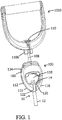
- FIG. 3 illustrates an exploded (disassembled) view of the sensor body 100 of FIGS. 1 and 2 .
- the sensor body 100 includes a female connector section 130 having bars 132 extending upwardly from the socket body sides 116, with the ends of the bars 132 being sandwiched and pinned between the depicted halves 134A and 134B of a male connector section.
- These bars 132 each can bear a force sensor (a load cell) 102, such that tension (or compression) between the male connector section 134A / 134B and the female connector section 130 - and thus on the bars 132 and the force sensors 102 thereon - results in a measurable signal representative of the force between the male and female connectors 104 and 106 of the sensor body 100.
- a force sensor a load cell
- the plug 110 and neck 108 of the male connector 104 are then shown in FIG. 3 between the halves 134A and 134B of the male connector section 134.
- the neck 108 is formed of a cable 136 terminating in crimped-on bosses 138 and 140, with the portion of the cable 136 extending between the male connector section 134A / 134B and the plug 110 being sheathed in a flexible sleeve 142 to define the portion of the neck 108 extending from the sensor body 100 to the plug 110.
- One boss 138 serves to retain the plug 110 on the cable 136, and the other boss 140 serves to retain a washer-like retention ring 144 next to the end of the cable 136 situated within the male connector section 134A / 134B.
- the plug 110 and neck 108 are firmly mounted on the sensor body 100. It is noted that while boss 140 and retention ring 144 help prevents the cable 136 of the neck 108 from being pulled out of the male connector section 134, cable 136 and/or neck 108 are preferably nonetheless rotatable with respect to the sensor body 100.
- FIG. 3 Other components depicted in FIG. 3 include a circuit board 156 which communicates with the force sensors 102, a power supply (battery) 158 which supplies power to the force sensors 102 and circuit board 156, a power button 160 for turning the aforementioned components on and off, and (optional) output devices (such as speaker 162, which rests below the circuit board 156 to emit sound through a grille 164 opening onto the body passage 118, light-emitting diodes (LEDs) or other sources of light, vibrator(s), etc.).
- the power button 160 may also be provided with one or more LEDs configured to indicate status or other information to the user.
- a tricolored (RGB) LED may emit blue light when the force sensors 102 are powered on and attempting to establish a connection with a client device, green light when a connection has been established, and red light if no connection is made after a certain period of time (or if the connection is lost after it is made).
- Fasteners 166 are provided for fixing the halves 134A and 134B of the male connector section together.
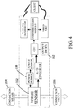
- Components of the circuit board 156 are then illustrated schematically in FIG. 4 (and are discussed in greater detail below), and include an analog to digital converter (A/D converter), a power sensor, a processor (CPU), and a communications module in connection with a wireless transmitter and a wired port.
- FIG. 3 does not depict these components, but the half 134A of the male connector section includes an aperture 168 in which the wired port is situated (the wired port preferably taking the form of a Universal Serial Bus connector or other connector allowing communication by wire with an external device).
- the force sensors 102 of FIG. 3 (merely depicted as “force sensor” 102 in FIG. 4 ) are supplied with an input voltage from the power supply 158, and generate an output voltage dependent on the input voltage and on any force exerted on the connection means (e.g., the male and female connectors 104 and 106).
- the output voltage is supplied to the analog to digital converter (A/D converter), which converts the output voltage into digital form and supplies it to the processor (CPU).
- the processor (CPU) also receives a calibration voltage signal from a power sensor in communication with the power supply 158.
- This calibration voltage signal allows the processor (CPU) to determine the concurrent input voltage to the force sensor 102, such that if the voltage of the power supply 158 decreases over time, the CPU can properly scale the output voltage provided by the force sensor 102 (and the A/D converter).
- the CPU converts the output voltage from the force sensor 102 into a force measurement, and may also perform additional processing steps, e.g., breaking the force readings into time-stamped packets, manipulating the force readings (e.g., integrating them over time to obtain power measurements), storing a history of force readings onto an on-board memory (not shown in FIG. 4 ) and performing analyses on recorded readings (related to, for example, progress over time), etc.
- the resulting data is then provided from the CPU to the communications module, which translates the data into a transmittable signal for communication to a "client" device via a wireless transmitter and/or via a wired port (with details of these devices being discussed below).
- the client device illustrated in FIG. 4 may take the form of one or more of a variety of devices which are capable of storing, displaying, and/or transmitting the data from the sensor body 100, including personal computers, mobile devices (such as mobile telephones like IPHONE manufactured by Apple Inc. of Cupertino, California, USA, personal digital assistants, handheld computers like IPAD manufactured by Apple Inc., and multimedia devices like IPOD manufactured by Apple Inc.), and game consoles (such as a PLAYSTATION console manufactured by the Sony Corporation of Tokyo, Japan, a NINTENDO console manufactured by Nintendo Co., Ltd., of Kyoto, Japan, or an XBOX console manufactured by the Microsoft Corporation of Redmond, Washington, USA).
- mobile devices such as mobile telephones like IPHONE manufactured by Apple Inc. of Cupertino, California, USA, personal digital assistants, handheld computers like IPAD manufactured by Apple Inc., and multimedia devices like IPOD manufactured by Apple Inc.
- game consoles such as a PLAYSTATION console manufactured by the Sony Corporation of Tokyo, Japan, a NINTE
- monitors / displays such as digitally-enabled televisions
- web-based applications accessible via net-enabled devices
- wearable devices such as sport watches and ankle bracelets
- the ability to supply data to mobile telephones and other mobile devices is particularly useful since this allows a user to readily store and transport both a data capture device (i.e., the sensor body 100) and a data review device (i.e., the mobile device and its associated visual and/or audio output components).
- the sensor body 100 might transmit exercise data to a web application, and the user might then be able to direct the browser of his/her mobile device to the web application, or call in to the web application, to obtain a visual and/or audio presentation of the data.
- the client device may then perform data recordation, audiovisual feedback, and other functionality, such as displaying live (real-time) force values in graphical form; tracking progress of the user and his/her exercise routine; indicating milestone force values using audiovisual cues; providing long-term data storage; reporting real-time and historical (or cumulative) data trends, calculations, and analyses; instructing users on proper exercise techniques and recommended exercise routines; providing a user interface allowing for the specification and adjustment of workout parameters, alarms, routines, etc.; and correlating data from the sensor body 100 with data from other devices, e.g., heart monitors or other physiological sensors.
- data recordation e.g., heart monitors or other physiological sensors.
- the configuration of the sensor body 100 it is possible to change the configuration of the sensor body 100 to perform some or all of these functions as well, e.g., by incorporating input and output devices (see, e.g., FIG. 4 ) into the sensor body 100 (such as input buttons / scroll wheels, an LCD display screen, a bank of LED lights, etc.), but it is preferred to restrict the functionality of the sensor body 100 to (primarily) the collection of force data, with most other functions being moved to a separate client device. This arrangement reduces the cost, complexity, and fragility of the sensor body 100, and also allows for easier upgrades in functionality because the client device might be reprogrammed or replaced as needed to provide desired functionality.
- input and output devices see, e.g., FIG. 4
- input buttons / scroll wheels such as input buttons / scroll wheels, an LCD display screen, a bank of LED lights, etc.
- audiovisual feedback of force measurements can be supplied by, for example, the aforementioned speaker 162 of FIG. 3 , LEDs or other sources of light, and/or LCD displays, as well as (or instead of) by a client device.
- the processor (CPU) of FIG. 4 is configured such that it can provide output via one or more output devices (such as the speaker 162 outputting sounds and/or voices, light sources, vibrators, etc.) in circumstances where no client device is available via wireless or wired communications and the sensor body 100 is made usable by itself as a standalone device.
- various audio messages can be associated with different information or events, with (for example) a first sound indicating that the measured force has met or exceeded a target force level, or a maximum force limit; a second sound signalling the time for which a pose or a motion should be sustained ("hold time”); a third sound if the measured force falls below the relaxation force for a given repetition; a fourth sound indicating the completion of an exercise, or the completion of an entire workout routine, or the attainment of a workout milestone (for example, total calories burned, total work done, etc.); and so forth.
- Audio cues in user-selected languages can provide instructions on (for example) how to perform various exercises, to move in various directions, or to use different muscles. Sound can also be used to provide rhythmic output, like that of a metronome, to assist with user timing of actions. Usefully, audio feedback permits a user to obtain feedback without needing to face and view a display.
- the sensor body 100 can include sufficient onboard memory that it can store the results of at least one of the user's exercise sessions for later downloading / transmission.
- the location of the wired port might be changed (if necessary) from that shown at 168 in FIG. 3 to, for example, the body passage 118, so that a removable memory device might be more securely affixed to the sensor body 100 in a non-protruding and relatively sheltered location.
- a removable display or the like e.g., a small LCD display
- a wired port situated at an appropriate location (though it is preferred that the sensor body 100 omit such components for the sake of durability, compactness, and being light weight).
- FIG. 2 illustrates a variety of components which can be attached to the male connector 104 in lieu of the rigid grasping loop 1000.
- a flexible belt-like grasping loop 2000 suitable for attachment about a wrist or ankle is shown connected to a female connector 2106 for receiving an elastic member 10, or for receiving the plug 110 of the male connector 104.
- Grasping loops can assume forms other than those provided by the grasping loops 1000 and 2000, and can include any rigid and/or flexible loop which is able to engage, or be engaged by, a part of the user's body, such as a handle loop which can be grasped by the user's hand, a stirrup that can be engaged by a user's foot, or a loop which can be engaged about a user's wrist, ankle, waist, head, neck, torso, etc.
- FIG. 2 also illustrates a female connector 3106 having three socket passages 3114, any one or more of which can receive an elastic member 10 or the plug 110, and it carries a strap 3000 bearing a carabiner 3170 (for attachment to a user's belt, to a suspended bar, a ring anchored to a wall or floor, etc.).
- Other components for attachment to the male connector 104 are also possible, including simply a structure which bears a female socket configured to complementarily receive the male plug 110, and which is anchored to a floor, wall, or other surroundings.
- the attachment of the foregoing and other components to the sensor body 100 can occur at the female connector 106 instead of (or in addition to) at the male connector 104, as by providing the components 1000, 2000, and 3000 with male plugs similar to plug 110 rather than female connectors, and engaging them within the socket passage 114 of the female connector 106.
- FIG. 2 also illustrates a possible arrangement wherein a variety of female connector sections 130, 4130, and 5130 are provided, each having a different form of connection means for attachment to elastic members 10 / 20 / 30 or other structures.
- the female connector sections 130, 4130, and 5130 may be interchangeably installable and removable on the male connector section 134, such as by using latches 4174 as discussed below for female connector section 4130.
- This female connector section 4130 is configured generally similarly to the female connector section 130 shown in FIGS. 1-3 , but contemplates that the force sensor bearing bars 132 seen in FIG.
- the female connector section 4130 bears slots 4172 for receiving the bars 132, and latches 4174 are pivotally connected to the female connector section 4130 near the slots 4172.
- the latches 4174 can be urged from the disengaged position shown in FIG. 5 to an engaged position (not shown) wherein pins or other structure (not shown) provided on or in connection with the latches 4174 engage the bars 132 to fix the male connector section 134 to the female connector section 4130.
- the female connector section 4130 also differs from the female connector section 130 in that it has a bearing member 4176 pivotally affixed at hinges 4178 such that it may move between a bearing position situated along the path of the socket passage 4114, and a non-bearing position situated outside (or to a lesser extent within) the path of the socket passage 4114.
- the bearing member 4176 In the bearing position, the bearing member 4176 is able to bear against any elastic member 20 extending through the socket passage 4114, and the bearing member 4176 is pivotally mounted with respect to the female connector section 4130 such that any attempt to withdraw the elastic member 20 from the socket passage 4114 (i.e., downwardly in FIG. 5 ) will tend to pull the bearing member 4176 into the socket passage 4114, thereby more tightly bearing against the elastic member 20.
- This arrangement is useful when the elastic member 20 lacks a member male connector (as shown in FIG. 5 ), or when one wishes to adjust the length of the elastic member 20 extending through the socket passage 4114, since the elastic member 20 may be extended through the socket passage 4114 to a desired extent, and the bearing member 4176 may then be urged against the elastic member 20 to fix it within the socket passage 4114. When desired, the bearing member 4176 may be moved to the non-bearing position to disengage the elastic member 20 to allow the elastic member 20 to freely travel through the socket passage 4114.
- FIG. 2 also illustrates a female connector section 5130 which resembles the female connector section 4130 of FIG. 5 , except it bears a female connector 5106 resembling the female connector 3106 shown at the upper right-hand side of FIG. 2 , with three socket passages 5114 that allow installation of one to three elastic members 30.
- the exercise devices and sensor body 100 shown in the accompanying drawings and discussed above are merely exemplary, and may assume a wide variety of configurations different from those noted, and may use components different from those noted.
- the force sensor 102 may take the form of single or multiple sensors, and need not take the form of a load cell.
- piezoelectric sensors, accelerometers, linear variable differential transformers (LVDTs), or any multi-axis sensors capable of measuring quantities such as torque, bending, stretching, pressure, etc. where desired, and/or other sensors may be used instead of or in addition to load cells.
- the wireless transmitter can take the form of a radio frequency transmitter (e.g., WiFi, Bluetooth, ANT, ANT+, ZigBee, etc.), an optical transmitter (e.g., an infrared transmitter), an ultrasonic transmitter, or the like.
- the wired port can take the form of an Ethernet port, a serial port, a parallel port, an IEEE 1394 interface (a "FireWire” port), or any other known connector suitable for allowing wired transmission of data.
- the power supply 158 while preferably taking the form of a rechargeable battery (which might be charged via the wired port or another connector), could instead be a replaceable battery, or might even be omitted in lieu of power supply via a wired connection (again via the wired port or another connector).
- the device may also be partly or entirely powered by converting pulling and/or pushing forces into energy that can power its components. That is, the energy expended while using the device could be harvested, such that kinetic energy is transduced into electrical and/or chemical energy that can be used to power its various parts and/or otherwise stored for later use (such as by recharging a battery).
- EMF electromagnetic field
- the female connector section 5130 of FIG. 2 may be used if it is desirable to attach one or more male members to the sensor body 100.
- the male connector section 134 might bear more than one male connector 104, e.g., more than one neck 108 and plug 110.
- different sides of the sensor body 100 can bear different combinations of one or more male and/or female connectors 104 and 106.
- the sensor body 100 might bear a male connector 104 extending along one axis, and multiple female connectors 106 spaced from the male connector 104 about the sensor body 100 (and the connectors 104 / 106 need not be situated along a common plane).
- the male connector 104 need not take the form of a flexible neck 108, and the neck 108 could be rigid instead. Such an arrangement is useful in situations where the sensor body 100 might be used to monitor forces subjecting the sensor body 100 to compression rather than tension.
- the neck 108 might also be extensible and retractable with respect to the sensor body 100, such that when the plug 110 and neck 108 are installed in a loop female connector 1106 (as in FIG. 1 ), the neck 108 might be withdrawn into the sensor body 100 such that the female connector 1106 is tightly sandwiched between the plug 110 and the sensor body 100.
- a simple way to attain such an arrangement is to provide the neck 108 as a threaded shaft which can be rotated to retract and extend it with respect to the sensor body 100.
- the neck 108 could be defined by a shaft bearing a protruding boss near its end opposite the plug 110, with the boss sliding within a keyway in the sensor body 100 as the neck 108 is pushed into a passage within the sensor body 100.
- An annular groove might then be defined about the passage at a certain depth therein, such that when the boss encounters the groove, the shaft can be rotated to move the boss out of the keyway and into the groove, preventing withdrawal of the shaft / neck 108 until the boss is rotated back into the keyway.
- Other retractable neck arrangements will be apparent to an ordinarily skilled designer.
- components and/or devices need not have complementary male and/or female connectors to interface with the exercise device.
- Other components may have members that are able to enter through the body passage 118 to connect to the exercise device.
- a cord, rope, chain, flat band, etc. can enter the body passage 118 and loop around the socket body 112, socket body sides 116, and/or the male connector section 134 and be tied to itself (via a knot) or otherwise attached to the exercise device.
- one or more rings, hooks, etc. (such as carabiner 3170) can be used to hook onto, for example, one or more socket body sides 116.
- the force sensor 102 would then be able to measure force exerted between, for example, a grasping loop and a member so attached. This greatly enhances the versatility, convenience, and usability of the exercise device by allowing it to interact with and engage even more types of components and devices.
- the grasping loops 1000 / 2000 of FIG. 2 could be joined directly (e.g., by welding) or indirectly (e.g., via webbing or other connection means) to the male connector section 134 or the female connector section 130.
- the other connector section could then be connected to an elastic member 10, an anchor, or another structure, whereby a user can grasp (or be grasped by) the grasping loop to exert force on the sensor body 100.
- the body passage 118 extending between opposite sides of the sensor body 100 might have one side blocked by a barrier.
- the side of the exercise device opposite the side with the slot 124 can include a wall extending from the sensor body 100 to the inner socket passage end 120, and extending between socket body sides 116. This would provide a confined space via which the socket passage 114 can be accessed by a male connector.
- the exercise device need not be provided with a body passage, in which case the sensor body 100 might be continuous with the socket body 112.
- grasping loops 1000 for gripping by a user (or gripping of a user) to act on the sensor body 100
- other forms of grips e.g., a simple bar with an elastic member 10 mounted to its length - can be used instead.
- the bearing member 4176 of FIGS. 3 and 5 is not restricted to the depicted ball-like form, and may take the form of a tongue, hook, or any other structure capable of impeding the socket passage 4114 and/or pressing against an elastic member 20. Further, the bearing member 4176 may move between bearing and nonbearing positions by other than pivotal motion, e.g., a bearing member 4176 might additionally or alternatively translate within the path of the socket passage 4114. Examples of additional or alternative bearing members include those found in U.S.
- elastic members in the form of elastic tubes with embedded plugs defining male connectors
- other forms of elastic members can be used instead, e.g., elastic tubes without male connectors (such as the one in FIG. 5 ), elastic cords, elastic straps, springs (made of, e.g., steel or other materials), or the like.
- elastic tubes without male connectors such as the one in FIG. 5
- elastic cords such as the one in FIG. 5
- elastic straps such as the one in FIG. 5
- springs made of, e.g., steel or other materials
- inelastic members rather than elastic members can be used with the claimed device - e.g., inelastic cords / cables, chains, straps, and the like - with the inelastic members being installed in generally the same manner as the aforementioned elastic members.
Landscapes
- Health & Medical Sciences (AREA)
- Life Sciences & Earth Sciences (AREA)
- Physical Education & Sports Medicine (AREA)
- General Health & Medical Sciences (AREA)
- Biophysics (AREA)
- Orthopedic Medicine & Surgery (AREA)
- Physics & Mathematics (AREA)
- Molecular Biology (AREA)
- Public Health (AREA)
- Medical Informatics (AREA)
- Biomedical Technology (AREA)
- Surgery (AREA)
- Animal Behavior & Ethology (AREA)
- Engineering & Computer Science (AREA)
- Heart & Thoracic Surgery (AREA)
- Veterinary Medicine (AREA)
- Pathology (AREA)
- Electromagnetism (AREA)
- Force Measurement Appropriate To Specific Purposes (AREA)
- Measuring Pulse, Heart Rate, Blood Pressure Or Blood Flow (AREA)
- Measurement Of The Respiration, Hearing Ability, Form, And Blood Characteristics Of Living Organisms (AREA)
Description
- This document concerns an invention relating generally to exercise devices, and more specifically to exercise devices having force sensors for measuring, recording, and/or providing feedback regarding a user's activity.
- Force sensors are sometimes incorporated into exercise devices for monitoring user activity, e.g., the amount of force applied, the duration of exercise, etc. The force sensors can allow a user (or others, e.g., trainers or physical therapists) to quantify, record, and analyze the user's activity with greater ease and certainty. For example, a sensor might precisely measure and record the amount of weight lifted during one exercise session, as well as the number of times it was lifted, the time over which it was lifted, etc., and the recorded data can then be compared to the results of a later exercise session to determine the user's progress.
- Often, the force sensors are built directly into the structures of the exercise devices. (See, e.g.,
U.S. Patents 5,271,416 ;6,612,170 ;7,510,509 ; andU.S. Patent Publication 2008/0242509 .) In this case, the force sensing functionality suffers from many drawbacks present in the exercise devices themselves. In particular, if the device is dedicated to the performance of only a single particular type of exercise, or a few types of exercises, the user's activity - which will often involve other types of exercise, and thus other exercise devices, as well - may not be fully captured by the force sensor. While a user might have a number of different exercise devices, each bearing its own force sensor for monitoring activities on its particular device, such an arrangement leads to greater expense, and to difficulties with collecting and organizing data from the various devices. - Some sensors are designed to be retrofit into preexisting exercise devices, as exemplified by
U.S. Patent 5,538,486 andU.S. Patent Publication 2008/0119763 . These devices suffer from the drawback that they are not easily installed in preexisting exercise devices, and moreover tend to be installable in only a limited number and type of exercise device. They also tend to add bulk, restrict range of motion, or otherwise detract from the utility of the exercise devices. -
US 2008/0119763 discloses acquisition, processing and reporting physical exercise data. In one example disclosed inUS 2008/0119763 a pod casing houses a load cell and circuitry, providing a rigid coupling element with openings for coupling devices connecting a handle or gripping element on one end and a resisting element or resistance transferring element on the other end. In another example disclosed inUS 2008/0119763 a pod is coupled to a wall track at one end using a universal joint or ball-in-socket joint or similar system, with the other end connecting to an elastic cable or stretching band. - It would be useful to have available inexpensive exercise devices which are capable of accommodating a wide variety of different exercises, and which allow rapid and convenient installation and removal of force sensors for monitoring user activity, wherein the force sensors (when installed) do not interfere with the functionality and usage of the exercise devices.
- The invention is defined in the appended claims.
- Referring to
FIGS. 1 and2 , an exemplary version of the exercise device as set out in the appended claims includes asensor body 100 having one or more force sensors therein (as seen at 102 inFIG. 3 ) or thereon, with means for connecting thesensor body 100 to other items -complementary male andfemale connectors 104 and 106 (best seen inFIG. 2 ) - situated on opposite sides of thesensor body 100. The force sensor(s) 102 sense pulling and/or pushing forces exerted between the twoconnectors connectors sensor body 100 to interface with other components having complementarily-shaped connectors, such as the elastic member 10 (which is shown having amember length 12 terminating in a membermale connector 14, an arrangement which is often formed by inserting a plug within an end of an elastic tube) and the grasping loop / handle 1000 (which is shown with a loop female connector /socket 1106 which is configured to complementarily receive the member male connector 14). Looking toFIG. 1 , if theelastic member 10 extends to an anchor (such as a wall or floor), and a user grips thegrasping loop 1000 and pulls on it to extend theelastic member 10, the force sensor(s) 102 between thegrasping loop 1000 and theelastic member 10 detect the force exerted along theelastic member 10 between thegrasping loop 1000 and the anchor. Since a wide variety of different forms ofelastic members 10 are available, as well as components configured to easily connect and disconnect to such elastic members 10 (such asgrasping loops 1000, bars, harnesses, etc.), thesensor body 100 can be inserted between selectedelastic members 10 and components to measure the forces generated by users during exercise. Since thesensor body 100 can be readily installed and removed between many different combinations ofelastic members 10 and components, asingle sensor body 100 used as a standalone device (used, for example, alternatively between two or more limbs) - or two ormore sensor bodies 100, one for each limb and/or other parts of the body - can be used across all (or most) of the exercises within a user's routine to capture characteristics of the user's activity. This greatly simplifies issues with data capture and calibration, since one need not compile data collected from numerous sensors having different calibration points. Further, since thesensor body 100 is easily retrofit into existing elastic member exercise devices, a user can incorporate one or more sensor bodies into his/her equipment to add force-monitoring capabilities, and can easily remove the sensor bodies if and when desired. In addition, the cost of force-monitoring exercise equipment is greatly reduced, particularly when the low cost of elastic member exercise devices is taken into account. - Referring to
FIG. 2 , themale connector 104 takes the form of aneck 108 extending from thesensor body 100 along a neck axis, with theneck 108 terminating in amale plug 110 having a configuration resembling that of themember male connector 14. As a result, themale plug 110 can be removably and replaceably inserted within the loopfemale connector 1106 of thegrasping loop 1000 in the same manner as themember male connector 14. Thefemale connector 106 take the form of asocket body 112 having asocket passage 114 configured similarly to the loopfemale connector 1106 of thegrasping loop 1000, and can therefore removably and replaceably receive the membermale connector 14 in complementary fashion (or themale plug 110, though themale plug 110 is not ordinarily inserted within thefemale connector 106 during normal use). Thus, thesensor body 100 is readily 30 installable between theelastic member 10 and thegrasping loop 1000, or between any other components having complementary connections (again, with examples being noted in the patents referenced in this document). - To review the
female connector 106 ofFIG. 2 in greater detail, thesocket body 112 includes a pair of opposingsocket body sides 116 spaced by abody passage 118 extending between opposite sides of thesensor body 100. Thebody passage 118 may be oriented along an axis which is perpendicular to the axis of theneck 108, and also perpendicular to the length of the socket passage 114 (which is preferably parallel with the axis of the neck 108). Thesocket passage 114 extends between an innersocket passage end 120 opening onto thebody passage 118, and an opposing outersocket passage end 122. Thesocket body 112 has aslot 124 opening onto thesocket passage 114, with theslot 124 extending along the length of thesocket passage 114 from the outersocket passage end 122 to the inner socket passage end 120 (thesocket passage 114 preferably has an enlarged inner diameter which effectively defines a pocket for receiving the member male connector 14). Theslot 124 is preferably sized such thatmale connectors 104, such as the membermale connector 14 of theelastic member 10, cannot pass through theslot 124. Anelastic member 10 bearing amember male connector 14 can then be easily installed into thesocket passage 114 by situating themember male connector 14 in thebody passage 118, and then pulling the length of theelastic member 10 along the slot 124 (while holding the membermale connector 14 within the body passage 118), such that the member length 12 (whose diameter decreases with elongation) can fit through theslot 124 and into thesocket passage 114. Themember male connector 14 can then be released to fit within thesocket passage 114 or adjacent to the innersocket passage end 120, with the length of theelastic member 10 extending from the outer socket passage end 122 (as seen inFIG. 1 ). - To review the
male connector 104 ofFIG. 2 in greater detail, theneck 108 is preferably flexible such that it will not contain any appreciable moment / bending forces during usage (e.g., if thegrasping loop 1000 is rocked about the axis of theneck 108 inFIG. 1 ), which could distort the force measurements generated by the force sensor(s) 102. In similar respects, theplug 110 and/orneck 108 are rotatable with respect to thesensor body 100, such that theneck 108 will not contain any appreciable torsional forces (e.g., if thegrasping loop 1000 is rotated about the axis of theneck 108 inFIG. 1 ). Theplug 110 may include structure which assists in firmly engaging it within a female connector, e.g., in the loopfemale connector 1106 of thegrasping loop 1000. As an example,FIG. 2 depicts theplug 110 with a protrudinglongitudinal flange 126 having a length oriented parallel to the neck axis, with thelongitudinal flange 126 deterring rotation of theplug 110 within the loopfemale connector 1106. A protrudinglateral flange 128 then has a length oriented perpendicularly to the neck axis (and to the longitudinal flange 126) to resist slippage of theplug 110 through the passage of thefemale connector 1106. - Keeping in mind that the foregoing discussion merely summarizes features of one exemplary preferred version of the invention, further details, variations, and advantages will be apparent from the remainder of this document in conjunction with the associated drawings.
-
-
FIG. 1 shows an exemplary exercise device featuring asensor body 100 connected to a grasping loop (handle) 1000 andelastic member 10. -
FIG. 2 shows the exercise device ofFIG. 1 with thegrasping loop 1000 andelastic member 10 disconnected from thesensor body 100, and withalternative components female connectors sensor body 100. -
FIG. 3 shows an exploded view of thesensor body 100 ofFIGS. 1 and2 . -
FIG. 4 schematically depicts the components and operation of thesensor body 100 ofFIGS. 1-3 . -
FIG. 5 provides a more detailed view of thefemale connector section 4130 ofFIG. 2 . - Expanding on the discussion above,
FIG. 3 illustrates an exploded (disassembled) view of thesensor body 100 ofFIGS. 1 and2 . Thesensor body 100 includes afemale connector section 130 havingbars 132 extending upwardly from thesocket body sides 116, with the ends of thebars 132 being sandwiched and pinned between the depictedhalves bars 132 each can bear a force sensor (a load cell) 102, such that tension (or compression) between themale connector section 134A / 134B and the female connector section 130 - and thus on thebars 132 and theforce sensors 102 thereon - results in a measurable signal representative of the force between the male andfemale connectors sensor body 100. - The
plug 110 andneck 108 of themale connector 104 are then shown inFIG. 3 between thehalves male connector section 134. Theneck 108 is formed of acable 136 terminating in crimped-onbosses cable 136 extending between themale connector section 134A / 134B and theplug 110 being sheathed in aflexible sleeve 142 to define the portion of theneck 108 extending from thesensor body 100 to theplug 110. Oneboss 138 serves to retain theplug 110 on thecable 136, and theother boss 140 serves to retain a washer-like retention ring 144 next to the end of thecable 136 situated within themale connector section 134A / 134B. When theretention ring 144 is installed within and between thehalves plug 110 andneck 108 are firmly mounted on thesensor body 100. It is noted that whileboss 140 andretention ring 144 help prevents thecable 136 of theneck 108 from being pulled out of themale connector section 134,cable 136 and/orneck 108 are preferably nonetheless rotatable with respect to thesensor body 100. - Other components depicted in
FIG. 3 include acircuit board 156 which communicates with theforce sensors 102, a power supply (battery) 158 which supplies power to theforce sensors 102 andcircuit board 156, apower button 160 for turning the aforementioned components on and off, and (optional) output devices (such asspeaker 162, which rests below thecircuit board 156 to emit sound through agrille 164 opening onto thebody passage 118, light-emitting diodes (LEDs) or other sources of light, vibrator(s), etc.). Thepower button 160 may also be provided with one or more LEDs configured to indicate status or other information to the user. For example, a tricolored (RGB) LED may emit blue light when theforce sensors 102 are powered on and attempting to establish a connection with a client device, green light when a connection has been established, and red light if no connection is made after a certain period of time (or if the connection is lost after it is made).Fasteners 166 are provided for fixing thehalves circuit board 156 are then illustrated schematically inFIG. 4 (and are discussed in greater detail below), and include an analog to digital converter (A/D converter), a power sensor, a processor (CPU), and a communications module in connection with a wireless transmitter and a wired port.FIG. 3 does not depict these components, but thehalf 134A of the male connector section includes anaperture 168 in which the wired port is situated (the wired port preferably taking the form of a Universal Serial Bus connector or other connector allowing communication by wire with an external device). - Turning then to
FIG. 4 , the foregoing components cooperate as follows. Theforce sensors 102 ofFIG. 3 (merely depicted as "force sensor" 102 inFIG. 4 ) are supplied with an input voltage from thepower supply 158, and generate an output voltage dependent on the input voltage and on any force exerted on the connection means (e.g., the male andfemale connectors 104 and 106). The output voltage is supplied to the analog to digital converter (A/D converter), which converts the output voltage into digital form and supplies it to the processor (CPU). The processor (CPU) also receives a calibration voltage signal from a power sensor in communication with thepower supply 158. This calibration voltage signal allows the processor (CPU) to determine the concurrent input voltage to theforce sensor 102, such that if the voltage of thepower supply 158 decreases over time, the CPU can properly scale the output voltage provided by the force sensor 102 (and the A/D converter). The CPU converts the output voltage from theforce sensor 102 into a force measurement, and may also perform additional processing steps, e.g., breaking the force readings into time-stamped packets, manipulating the force readings (e.g., integrating them over time to obtain power measurements), storing a history of force readings onto an on-board memory (not shown inFIG. 4 ) and performing analyses on recorded readings (related to, for example, progress over time), etc. The resulting data is then provided from the CPU to the communications module, which translates the data into a transmittable signal for communication to a "client" device via a wireless transmitter and/or via a wired port (with details of these devices being discussed below). - The client device illustrated in
FIG. 4 may take the form of one or more of a variety of devices which are capable of storing, displaying, and/or transmitting the data from thesensor body 100, including personal computers, mobile devices (such as mobile telephones like IPHONE manufactured by Apple Inc. of Cupertino, California, USA, personal digital assistants, handheld computers like IPAD manufactured by Apple Inc., and multimedia devices like IPOD manufactured by Apple Inc.), and game consoles (such as a PLAYSTATION console manufactured by the Sony Corporation of Tokyo, Japan, a NINTENDO console manufactured by Nintendo Co., Ltd., of Kyoto, Japan, or an XBOX console manufactured by the Microsoft Corporation of Redmond, Washington, USA). These are merely preferred client devices, and a wide variety of other clients are also possible, e.g., various types of monitors / displays (such as digitally-enabled televisions), web-based applications (accessible via net-enabled devices), wearable devices (such as sport watches and ankle bracelets), etc. The ability to supply data to mobile telephones and other mobile devices is particularly useful since this allows a user to readily store and transport both a data capture device (i.e., the sensor body 100) and a data review device (i.e., the mobile device and its associated visual and/or audio output components). In this respect, it is notable that thesensor body 100 might transmit exercise data to a web application, and the user might then be able to direct the browser of his/her mobile device to the web application, or call in to the web application, to obtain a visual and/or audio presentation of the data. - The client device may then perform data recordation, audiovisual feedback, and other functionality, such as displaying live (real-time) force values in graphical form; tracking progress of the user and his/her exercise routine; indicating milestone force values using audiovisual cues; providing long-term data storage; reporting real-time and historical (or cumulative) data trends, calculations, and analyses; instructing users on proper exercise techniques and recommended exercise routines; providing a user interface allowing for the specification and adjustment of workout parameters, alarms, routines, etc.; and correlating data from the
sensor body 100 with data from other devices, e.g., heart monitors or other physiological sensors. It is possible to change the configuration of thesensor body 100 to perform some or all of these functions as well, e.g., by incorporating input and output devices (see, e.g.,FIG. 4 ) into the sensor body 100 (such as input buttons / scroll wheels, an LCD display screen, a bank of LED lights, etc.), but it is preferred to restrict the functionality of thesensor body 100 to (primarily) the collection of force data, with most other functions being moved to a separate client device. This arrangement reduces the cost, complexity, and fragility of thesensor body 100, and also allows for easier upgrades in functionality because the client device might be reprogrammed or replaced as needed to provide desired functionality. - Where audiovisual feedback of force measurements (or other information) is provided, it can be supplied by, for example, the
aforementioned speaker 162 ofFIG. 3 , LEDs or other sources of light, and/or LCD displays, as well as (or instead of) by a client device. Most preferably, the processor (CPU) ofFIG. 4 is configured such that it can provide output via one or more output devices (such as thespeaker 162 outputting sounds and/or voices, light sources, vibrators, etc.) in circumstances where no client device is available via wireless or wired communications and thesensor body 100 is made usable by itself as a standalone device. In this case, various audio messages can be associated with different information or events, with (for example) a first sound indicating that the measured force has met or exceeded a target force level, or a maximum force limit; a second sound signalling the time for which a pose or a motion should be sustained ("hold time"); a third sound if the measured force falls below the relaxation force for a given repetition; a fourth sound indicating the completion of an exercise, or the completion of an entire workout routine, or the attainment of a workout milestone (for example, total calories burned, total work done, etc.); and so forth. Audio cues in user-selected languages (as well as visual and/or tactile cues using various output devices) can provide instructions on (for example) how to perform various exercises, to move in various directions, or to use different muscles. Sound can also be used to provide rhythmic output, like that of a metronome, to assist with user timing of actions. Usefully, audio feedback permits a user to obtain feedback without needing to face and view a display. - Regarding the aforementioned possibility of using the
sensor body 100 where no client device is available, it can be useful for thesensor body 100 to include sufficient onboard memory that it can store the results of at least one of the user's exercise sessions for later downloading / transmission. In this respect, if a removable memory is desired, the location of the wired port might be changed (if necessary) from that shown at 168 inFIG. 3 to, for example, thebody passage 118, so that a removable memory device might be more securely affixed to thesensor body 100 in a non-protruding and relatively sheltered location. In similar respects, a removable display or the like (e.g., a small LCD display) might be installed on thesensor body 100 via a wired port situated at an appropriate location (though it is preferred that thesensor body 100 omit such components for the sake of durability, compactness, and being light weight). - Turning back to
FIGS. 1 and2 , it should be understood that thesensor body 100 may be interposed between a wide variety of components other than the graspingloop 1000 and theelastic member 10.FIG. 2 illustrates a variety of components which can be attached to themale connector 104 in lieu of the rigidgrasping loop 1000. A flexible belt-likegrasping loop 2000 suitable for attachment about a wrist or ankle is shown connected to afemale connector 2106 for receiving anelastic member 10, or for receiving theplug 110 of themale connector 104. Grasping loops can assume forms other than those provided by the graspingloops FIG. 2 also illustrates afemale connector 3106 having threesocket passages 3114, any one or more of which can receive anelastic member 10 or theplug 110, and it carries astrap 3000 bearing a carabiner 3170 (for attachment to a user's belt, to a suspended bar, a ring anchored to a wall or floor, etc.). Other components for attachment to themale connector 104 are also possible, including simply a structure which bears a female socket configured to complementarily receive themale plug 110, and which is anchored to a floor, wall, or other surroundings. The attachment of the foregoing and other components to thesensor body 100 can occur at thefemale connector 106 instead of (or in addition to) at themale connector 104, as by providing thecomponents socket passage 114 of thefemale connector 106. -
FIG. 2 also illustrates a possible arrangement wherein a variety offemale connector sections elastic members 10 / 20 / 30 or other structures. Thefemale connector sections male connector section 134, such as by usinglatches 4174 as discussed below forfemale connector section 4130. Initially refer to thefemale connector section 4130, which is illustrated in greater detail inFIG. 5 . Thisfemale connector section 4130 is configured generally similarly to thefemale connector section 130 shown inFIGS. 1-3 , but contemplates that the forcesensor bearing bars 132 seen inFIG. 3 protrude from themale connector section 134 rather than thefemale connector section 4130 to be received and pinned (or otherwise engaged) within thefemale connector section 4130. Thefemale connector section 4130 bearsslots 4172 for receiving thebars 132, and latches 4174 are pivotally connected to thefemale connector section 4130 near theslots 4172. Thelatches 4174 can be urged from the disengaged position shown inFIG. 5 to an engaged position (not shown) wherein pins or other structure (not shown) provided on or in connection with thelatches 4174 engage thebars 132 to fix themale connector section 134 to thefemale connector section 4130. Thefemale connector section 4130 also differs from thefemale connector section 130 in that it has a bearingmember 4176 pivotally affixed athinges 4178 such that it may move between a bearing position situated along the path of thesocket passage 4114, and a non-bearing position situated outside (or to a lesser extent within) the path of thesocket passage 4114. In the bearing position, the bearingmember 4176 is able to bear against anyelastic member 20 extending through thesocket passage 4114, and the bearingmember 4176 is pivotally mounted with respect to thefemale connector section 4130 such that any attempt to withdraw theelastic member 20 from the socket passage 4114 (i.e., downwardly inFIG. 5 ) will tend to pull the bearingmember 4176 into thesocket passage 4114, thereby more tightly bearing against theelastic member 20. This arrangement is useful when theelastic member 20 lacks a member male connector (as shown inFIG. 5 ), or when one wishes to adjust the length of theelastic member 20 extending through thesocket passage 4114, since theelastic member 20 may be extended through thesocket passage 4114 to a desired extent, and the bearingmember 4176 may then be urged against theelastic member 20 to fix it within thesocket passage 4114. When desired, the bearingmember 4176 may be moved to the non-bearing position to disengage theelastic member 20 to allow theelastic member 20 to freely travel through thesocket passage 4114. -
FIG. 2 also illustrates afemale connector section 5130 which resembles thefemale connector section 4130 ofFIG. 5 , except it bears a female connector 5106 resembling thefemale connector 3106 shown at the upper right-hand side ofFIG. 2 , with threesocket passages 5114 that allow installation of one to threeelastic members 30. - Preferred versions of the invention have been reviewed in the foregoing discussion to illustrate different possible features of the invention and the varying ways in which these features may be combined. Apart from combining the different features of the foregoing versions in varying ways, other modifications are also considered to be within the scope of the invention. Following is an exemplary list of such modifications.
- Initially, it must be kept in mind that the exercise devices and
sensor body 100 shown in the accompanying drawings and discussed above are merely exemplary, and may assume a wide variety of configurations different from those noted, and may use components different from those noted. Regarding components, theforce sensor 102 may take the form of single or multiple sensors, and need not take the form of a load cell. As examples, piezoelectric sensors, accelerometers, linear variable differential transformers (LVDTs), or any multi-axis sensors capable of measuring quantities such as torque, bending, stretching, pressure, etc. where desired, and/or other sensors may be used instead of or in addition to load cells. The wireless transmitter can take the form of a radio frequency transmitter (e.g., WiFi, Bluetooth, ANT, ANT+, ZigBee, etc.), an optical transmitter (e.g., an infrared transmitter), an ultrasonic transmitter, or the like. The wired port can take the form of an Ethernet port, a serial port, a parallel port, an IEEE 1394 interface (a "FireWire" port), or any other known connector suitable for allowing wired transmission of data. - The
power supply 158, while preferably taking the form of a rechargeable battery (which might be charged via the wired port or another connector), could instead be a replaceable battery, or might even be omitted in lieu of power supply via a wired connection (again via the wired port or another connector). The device may also be partly or entirely powered by converting pulling and/or pushing forces into energy that can power its components. That is, the energy expended while using the device could be harvested, such that kinetic energy is transduced into electrical and/or chemical energy that can be used to power its various parts and/or otherwise stored for later use (such as by recharging a battery). This can be accomplished by any suitable means available, such as by incorporating piezoelectric crystals that generate voltage when mechanically deformed, or through the movement of magnets in an electromagnetic generator (caused by movements of the device) providing a rate of change of magnetic flux and inducing an electromagnetic field (EMF) on the coils. - As noted previously, the
female connector section 5130 ofFIG. 2 may be used if it is desirable to attach one or more male members to thesensor body 100. In similar respects, themale connector section 134 might bear more than onemale connector 104, e.g., more than oneneck 108 and plug 110. It is also possible that different sides of thesensor body 100 can bear different combinations of one or more male and/orfemale connectors sensor body 100 might bear amale connector 104 extending along one axis, and multiplefemale connectors 106 spaced from themale connector 104 about the sensor body 100 (and theconnectors 104 / 106 need not be situated along a common plane). - The
male connector 104 need not take the form of aflexible neck 108, and theneck 108 could be rigid instead. Such an arrangement is useful in situations where thesensor body 100 might be used to monitor forces subjecting thesensor body 100 to compression rather than tension. Theneck 108 might also be extensible and retractable with respect to thesensor body 100, such that when theplug 110 andneck 108 are installed in a loop female connector 1106 (as inFIG. 1 ), theneck 108 might be withdrawn into thesensor body 100 such that thefemale connector 1106 is tightly sandwiched between theplug 110 and thesensor body 100. A simple way to attain such an arrangement is to provide theneck 108 as a threaded shaft which can be rotated to retract and extend it with respect to thesensor body 100. As an alternative, theneck 108 could be defined by a shaft bearing a protruding boss near its end opposite theplug 110, with the boss sliding within a keyway in thesensor body 100 as theneck 108 is pushed into a passage within thesensor body 100. An annular groove might then be defined about the passage at a certain depth therein, such that when the boss encounters the groove, the shaft can be rotated to move the boss out of the keyway and into the groove, preventing withdrawal of the shaft /neck 108 until the boss is rotated back into the keyway. Other retractable neck arrangements will be apparent to an ordinarily skilled designer. - It is noted that other components and/or devices (not part of the claimed device) need not have complementary male and/or female connectors to interface with the exercise device. Other components may have members that are able to enter through the
body passage 118 to connect to the exercise device. For example, a cord, rope, chain, flat band, etc., can enter thebody passage 118 and loop around thesocket body 112, socket body sides 116, and/or themale connector section 134 and be tied to itself (via a knot) or otherwise attached to the exercise device. Alternatively or additionally, one or more rings, hooks, etc. (such as carabiner 3170) can be used to hook onto, for example, one or more socket body sides 116. Theforce sensor 102 would then be able to measure force exerted between, for example, a grasping loop and a member so attached. This greatly enhances the versatility, convenience, and usability of the exercise device by allowing it to interact with and engage even more types of components and devices. - As another exemplary variation, the grasping
loops 1000 / 2000 ofFIG. 2 (or other forms of grasping loops) could be joined directly (e.g., by welding) or indirectly (e.g., via webbing or other connection means) to themale connector section 134 or thefemale connector section 130. The other connector section could then be connected to anelastic member 10, an anchor, or another structure, whereby a user can grasp (or be grasped by) the grasping loop to exert force on thesensor body 100. - The
body passage 118 extending between opposite sides of thesensor body 100 might have one side blocked by a barrier. For example, the side of the exercise device opposite the side with theslot 124 can include a wall extending from thesensor body 100 to the innersocket passage end 120, and extending between socket body sides 116. This would provide a confined space via which thesocket passage 114 can be accessed by a male connector. Alternatively, the exercise device need not be provided with a body passage, in which case thesensor body 100 might be continuous with thesocket body 112. - While the foregoing discussion has generally spoken of the use of grasping
loops 1000 for gripping by a user (or gripping of a user) to act on thesensor body 100, other forms of grips - e.g., a simple bar with anelastic member 10 mounted to its length - can be used instead. - The bearing
member 4176 ofFIGS. 3 and5 is not restricted to the depicted ball-like form, and may take the form of a tongue, hook, or any other structure capable of impeding thesocket passage 4114 and/or pressing against anelastic member 20. Further, the bearingmember 4176 may move between bearing and nonbearing positions by other than pivotal motion, e.g., a bearingmember 4176 might additionally or alternatively translate within the path of thesocket passage 4114. Examples of additional or alternative bearing members include those found in U.S. -
- Finally, while this document has generally discussed the use of elastic members in the form of elastic tubes with embedded plugs defining male connectors, it should be understood that other forms of elastic members can be used instead, e.g., elastic tubes without male connectors (such as the one in
FIG. 5 ), elastic cords, elastic straps, springs (made of, e.g., steel or other materials), or the like. Where no member male connector (such as themember male connector 14 ofFIG. 2 ) is present, these can be used in conjunction with afemale connector 106 having a bearing member 4176 (as inFIG. 2 ), or they could simply be inserted through asocket passage 114 of afemale connector 106 and then tied about thefemale connector 106, or they could be knotted to prevent their travel through thesocket passage 114, to engage them to thesensor body 100. Further, other inelastic members rather than elastic members can be used with the claimed device - e.g., inelastic cords / cables, chains, straps, and the like - with the inelastic members being installed in generally the same manner as the aforementioned elastic members. - The invention is not intended to be limited to the preferred versions of the invention described above, but rather is intended to be limited only by the claims set out below.
Claims (11)
- An exercise device including:a sensor body (100) having a force sensor (102),wherein the sensor body (100) comprises complimentary male and female connectors (104;106) situated on opposite sides of the sensor body (100);the male connector (104) comprises a neck (108) for connecting to a grasping handle (1000, 2000, 3000) and the female connector (106) comprises a socket body (112) for connecting to an elastic member (12), and the neck (108) has a length extending from the sensor body (100), the neck (108) having a male plug (110) situated thereon spaced from the sensor body (100), with the male plug (110) having portions extending outwardly from the circumference of the neck (108) to engage a connection portion (1106) of said grasping handle (1000, 2000, 3000);whereby the force sensor (102) senses force exerted between the male plug (110) and the socket body (112);the socket body (112) is defined by a socket passage (114) configured such that the socket passage (114) can receive a member male connector (14) therein, but prohibits passage of the member male connector (14) through the socket passage (114);wherein the male plug (110) is rotatable with respect to the neck (108) and/or the neck (108) is rotatable with respect to the sensor body (100) such that the neck (108) will not contain any appreciable torsional forces.
- The exercise device of claim 1 wherein the neck (108) is flexible.
- The exercise device of claim 2 wherein the socket body (112):a) defines a terminal end of the sensor body (100), andb) is removably and replaceably affixed to the sensor body (100).
- The exercise device of claim 1 wherein the neck (108) is retractable with respect to the sensor body (100), such that the distance between the sensor body (100) and the male plug (110) is adjustable.
- The exercise device of claim 1 wherein the socket passage (114):a) extends between opposing socket passage ends (120), andb) includes a slot (124) extending between the opposing socket passage ends (120) and opening onto the socket passage (114).
- The exercise device of claim 1 wherein the exercise device further includes a bearing member (4176) movably affixed to at least one of the socket body (112) and the sensor body (100), the bearing member (4176) being movable between:a) a bearing position adjacent to the socket passage (114), andb) a non-bearing position spaced from the bearing position.
- The exercise device of claim 1 wherein the socket body (112) includes a pair of opposing socket body (112) sides extending from the sensor body (100), with a body passage (118):a) defined between the socket body sides, andb) extending between opposite first and second faces of the exercise device from an intermediate face defined at an end of the socket body (112).
- The exercise device of claim 1 wherein the outwardly extending portions of the male plug (110) include a longitudinal flange (126) having a length oriented at least substantially parallel with the length of the neck (108).
- The exercise device of claim 8 wherein the outwardly extending portions of the male plug (110) further include a lateral flange (128) having a length oriented at least substantially perpendicular to the length of the neck (108).
- The exercise device of claim 1, further comprising an elastic member (10), wherein the elastic member (10) has the member male connector (14) thereon, wherein the member male connector (14) is:a) removably insertable within the socket passage (114), andb) configured such that it cannot be pulled through the socket passage (114).
- The exercise device of claim 10 further including a grasping loop (1000) having a loop female connector (1106) thereon, wherein:a) the male plug (110) of the neck (108) is removably insertable within the loop female connector (1106), andb) the force sensor (102) senses force exerted between the elastic member (10) and the grasping loop (1000).
Applications Claiming Priority (2)
| Application Number | Priority Date | Filing Date | Title |
|---|---|---|---|
| US24822709P | 2009-10-02 | 2009-10-02 | |
| PCT/US2010/051123 WO2011041678A1 (en) | 2009-10-02 | 2010-10-01 | Exercise devices with force sensors |
Publications (3)
| Publication Number | Publication Date |
|---|---|
| EP2482722A1 EP2482722A1 (en) | 2012-08-08 |
| EP2482722A4 EP2482722A4 (en) | 2013-04-10 |
| EP2482722B1 true EP2482722B1 (en) | 2016-12-07 |
Family
ID=43826670
Family Applications (1)
| Application Number | Title | Priority Date | Filing Date |
|---|---|---|---|
| EP10821332.3A Not-in-force EP2482722B1 (en) | 2009-10-02 | 2010-10-01 | Exercise devices with force sensors |
Country Status (4)
| Country | Link |
|---|---|
| US (1) | US8491446B2 (en) |
| EP (1) | EP2482722B1 (en) |
| CA (1) | CA2775585C (en) |
| WO (1) | WO2011041678A1 (en) |
Families Citing this family (87)
| Publication number | Priority date | Publication date | Assignee | Title |
|---|---|---|---|---|
| US7148879B2 (en) | 2000-07-06 | 2006-12-12 | At&T Corp. | Bioacoustic control system, method and apparatus |
| US20140031182A1 (en) * | 2008-08-19 | 2014-01-30 | Darren Donofrio | Wall-Mounted Home Fitness Training Equipment |
| US20110152045A1 (en) * | 2009-12-23 | 2011-06-23 | Horne Edward F | Apparatus and method for counter-resistance exercise |
| US20120035020A1 (en) * | 2010-07-28 | 2012-02-09 | Nony Kamm | Device Method and System for Exercising |
| US11064910B2 (en) | 2010-12-08 | 2021-07-20 | Activbody, Inc. | Physical activity monitoring system |
| US8908894B2 (en) | 2011-12-01 | 2014-12-09 | At&T Intellectual Property I, L.P. | Devices and methods for transferring data through a human body |
| US9339691B2 (en) | 2012-01-05 | 2016-05-17 | Icon Health & Fitness, Inc. | System and method for controlling an exercise device |
| US8911335B2 (en) | 2012-03-13 | 2014-12-16 | Speed Tracs America LLC | Athlete training and monitoring system |
| US9561400B2 (en) * | 2012-05-07 | 2017-02-07 | Bandcizer Aps | Sensor unit for quantification of physical training with rubber band |
| US10102345B2 (en) | 2012-06-19 | 2018-10-16 | Activbody, Inc. | Personal wellness management platform |
| US10133849B2 (en) | 2012-06-19 | 2018-11-20 | Activbody, Inc. | Merchandizing, socializing, and/or gaming via a personal wellness device and/or a personal wellness platform |
| US9230064B2 (en) | 2012-06-19 | 2016-01-05 | EZ as a Drink Productions, Inc. | Personal wellness device |
| US8961379B2 (en) * | 2012-08-14 | 2015-02-24 | Spri Products, Inc. | Elongate member for forming an exercise device |
| US9050484B2 (en) | 2012-08-14 | 2015-06-09 | Spri Products, Inc. | Exercise device and handle for same |
| US8876678B2 (en) | 2012-08-14 | 2014-11-04 | Spri Products, Inc. | Exercise device and handle for same |
| US8864587B2 (en) | 2012-10-03 | 2014-10-21 | Sony Corporation | User device position indication for security and distributed race challenges |
| JP5925395B2 (en) * | 2013-01-16 | 2016-05-25 | ホールマーク,ティモシー,エム | Mobile training device |
| US9161708B2 (en) * | 2013-02-14 | 2015-10-20 | P3 Analytics, Inc. | Generation of personalized training regimens from motion capture data |
| GB2512045A (en) * | 2013-03-12 | 2014-09-24 | Chang Yow Technologies Internat Co Ltd | Fitness equipment equipped with wireless sensor pack |
| CN104884133B (en) | 2013-03-14 | 2018-02-23 | 艾肯运动与健康公司 | Force exercise equipment with flywheel |
| US9555280B2 (en) | 2013-03-15 | 2017-01-31 | Arqex Outdoor Fitness Systems, Llc | Attachment assembly for an exercise device and an exercise device incorporating the same |
| US9555278B2 (en) * | 2013-03-15 | 2017-01-31 | Arqfx Outdoor Fitness Systems, Llc | Strength training and stretching system and resistance band assembly for use therewith |
| US9724553B2 (en) | 2013-03-15 | 2017-08-08 | Arqex Outdoor Fitness Systems, Llc | Resistance band assembly and a method of varying a resistive force applied thereby |
| US9682267B2 (en) | 2013-03-15 | 2017-06-20 | Arqex Outdoor Fitness Systems, Llc | Insert for use with a resistance band assembly and a method of using the same |
| WO2014174475A1 (en) * | 2013-04-24 | 2014-10-30 | Nkosi Mandla Cassy | An exercise device |
| US9248331B1 (en) | 2013-05-07 | 2016-02-02 | Tiger Brands Athletics, Inc. | Resistance band with markings |
| US9229476B2 (en) | 2013-05-08 | 2016-01-05 | EZ as a Drink Productions, Inc. | Personal handheld electronic device with a touchscreen on a peripheral surface |
| US9262064B2 (en) | 2013-07-09 | 2016-02-16 | EZ as a Drink Productions, Inc. | Handheld computing platform with integrated pressure sensor and associated methods of use |
| US20150082167A1 (en) | 2013-09-17 | 2015-03-19 | Sony Corporation | Intelligent device mode shifting based on activity |
| US10108984B2 (en) | 2013-10-29 | 2018-10-23 | At&T Intellectual Property I, L.P. | Detecting body language via bone conduction |
| US9594433B2 (en) | 2013-11-05 | 2017-03-14 | At&T Intellectual Property I, L.P. | Gesture-based controls via bone conduction |
| US9349280B2 (en) | 2013-11-18 | 2016-05-24 | At&T Intellectual Property I, L.P. | Disrupting bone conduction signals |
| US10678322B2 (en) | 2013-11-18 | 2020-06-09 | At&T Intellectual Property I, L.P. | Pressure sensing via bone conduction |
| US9715774B2 (en) | 2013-11-19 | 2017-07-25 | At&T Intellectual Property I, L.P. | Authenticating a user on behalf of another user based upon a unique body signature determined through bone conduction signals |
| US9405892B2 (en) | 2013-11-26 | 2016-08-02 | At&T Intellectual Property I, L.P. | Preventing spoofing attacks for bone conduction applications |
| EP3974036B1 (en) | 2013-12-26 | 2024-06-19 | iFIT Inc. | Magnetic resistance mechanism in a cable machine |
| US9269119B2 (en) | 2014-01-22 | 2016-02-23 | Sony Corporation | Devices and methods for health tracking and providing information for improving health |
| US10112068B2 (en) * | 2014-03-06 | 2018-10-30 | Dov Medina | Exercise apparatus and method |
| WO2015138339A1 (en) | 2014-03-10 | 2015-09-17 | Icon Health & Fitness, Inc. | Pressure sensor to quantify work |
| US10124246B2 (en) | 2014-04-21 | 2018-11-13 | Activbody, Inc. | Pressure sensitive peripheral devices, and associated methods of use |
| WO2015191445A1 (en) | 2014-06-09 | 2015-12-17 | Icon Health & Fitness, Inc. | Cable system incorporated into a treadmill |
| WO2015195965A1 (en) | 2014-06-20 | 2015-12-23 | Icon Health & Fitness, Inc. | Post workout massage device |
| US9589482B2 (en) | 2014-09-10 | 2017-03-07 | At&T Intellectual Property I, L.P. | Bone conduction tags |
| US10045732B2 (en) | 2014-09-10 | 2018-08-14 | At&T Intellectual Property I, L.P. | Measuring muscle exertion using bone conduction |
| US9582071B2 (en) | 2014-09-10 | 2017-02-28 | At&T Intellectual Property I, L.P. | Device hold determination using bone conduction |
| US9882992B2 (en) | 2014-09-10 | 2018-01-30 | At&T Intellectual Property I, L.P. | Data session handoff using bone conduction |
| USD794728S1 (en) * | 2014-09-29 | 2017-08-15 | Circuband Limited | Exercise equipment handle |
| US9600079B2 (en) | 2014-10-15 | 2017-03-21 | At&T Intellectual Property I, L.P. | Surface determination via bone conduction |
| US9480866B2 (en) * | 2014-10-21 | 2016-11-01 | The Boeing Company | Line connector having a link detection system and method of making same |
| DE102015100960B4 (en) * | 2015-01-22 | 2020-02-13 | RPC Rehacare UG (haftungsbeschrankt) & Co. KG | Training device to improve strength, flexibility, endurance and control at various joints and their surrounding soft tissue structures |
| US9782624B2 (en) * | 2015-02-03 | 2017-10-10 | Kiio Inc. | Interchangeable grip and pinch strength assessor and exerciser |
| US10391361B2 (en) | 2015-02-27 | 2019-08-27 | Icon Health & Fitness, Inc. | Simulating real-world terrain on an exercise device |
| CN108778129A (en) * | 2015-12-11 | 2018-11-09 | 精密生物力学有限公司 | The improvement of muscle strength measuring device and relevant improvement |
| US10272317B2 (en) | 2016-03-18 | 2019-04-30 | Icon Health & Fitness, Inc. | Lighted pace feature in a treadmill |
| US10625137B2 (en) | 2016-03-18 | 2020-04-21 | Icon Health & Fitness, Inc. | Coordinated displays in an exercise device |
| US10493349B2 (en) | 2016-03-18 | 2019-12-03 | Icon Health & Fitness, Inc. | Display on exercise device |
| US10918901B2 (en) * | 2016-04-20 | 2021-02-16 | Shapelog, Inc. | Sensor equipped resistance training grip |
| GB2552203A (en) * | 2016-07-14 | 2018-01-17 | Savaivongthong Kongkham | A Portable exercise device |
| US10671705B2 (en) | 2016-09-28 | 2020-06-02 | Icon Health & Fitness, Inc. | Customizing recipe recommendations |
| AU2017204276C1 (en) * | 2017-06-23 | 2022-06-30 | Kangatech Pty Ltd | A Testing and Training Apparatus |
| US10729369B2 (en) * | 2017-06-23 | 2020-08-04 | Kangatech Pty Ltd. | Testing and training apparatus |
| ES2699440A1 (en) | 2017-08-11 | 2019-02-11 | Bio Sensing Solutions S L | SENSOR, SYSTEM AND METHOD TO DETECT AND SUPERVISE AN ACTION |
| DE102017120472A1 (en) * | 2017-09-06 | 2019-03-07 | Heyo Mennenga | Sports equipment for muscle training |
| US10384094B1 (en) * | 2017-12-22 | 2019-08-20 | Timothy D. Newman | Elastic cord with safety sleeve |
| US10857425B2 (en) | 2018-03-05 | 2020-12-08 | Rodney Harold Thomas | Resistance-band exercise monitoring device and associated methods |
| US11027172B2 (en) | 2018-03-23 | 2021-06-08 | Thomas W. OSBRINK | Device and methods for improved resistance training |
| US11857837B2 (en) * | 2018-05-17 | 2024-01-02 | Trustees Of Dartmouth College | Instrumented resistance exercise device |
| WO2019241797A1 (en) * | 2018-06-15 | 2019-12-19 | Rhino Boss Llc | Portable resistance workout apparatuses and systems |
| US10960254B2 (en) * | 2018-07-24 | 2021-03-30 | GH Product Design and Development, LLC | Exercise device |
| US10831316B2 (en) | 2018-07-26 | 2020-11-10 | At&T Intellectual Property I, L.P. | Surface interface |
| US20200206556A1 (en) * | 2018-12-26 | 2020-07-02 | Juan Ernesto Souffrain | Smart resistance bands system |
| US12036024B2 (en) | 2019-02-27 | 2024-07-16 | President And Fellows Of Harvard College | System and method for quantification of exercise and physical therapy |
| CN213941232U (en) | 2019-10-09 | 2021-08-13 | 希尔-罗姆服务公司 | person support device |
| US11247080B2 (en) * | 2019-10-10 | 2022-02-15 | Saudi Arabian Oil Company | Systems, methods, and apparatuses for ensuring worker safety |
| DE102020103448A1 (en) | 2020-02-11 | 2021-08-12 | Red Rab GmbH | Training device and length adjustment device for a training device |
| US11701547B2 (en) | 2020-05-06 | 2023-07-18 | PT Genie, LLC | Measuring a pull force on an exercise band |
| US12320406B2 (en) | 2021-04-08 | 2025-06-03 | Exemplar Design, Llc | Attachment mechanism between a base and a body secured or gripped object |
| AU2022206689A1 (en) * | 2021-07-17 | 2023-02-02 | DELAND, Dominic Roger | Weightlifting system and method for analysing lift motion |
| USD1049271S1 (en) | 2021-07-26 | 2024-10-29 | Fitnix Llc | Hand grip exercise device |
| US20230110715A1 (en) | 2021-10-12 | 2023-04-13 | Hygear Inc. | Interactive resistance band training systems |
| US12296215B2 (en) * | 2022-02-11 | 2025-05-13 | Travis Jezwinski | Resistance bands apparatus |
| WO2023194962A1 (en) * | 2022-04-06 | 2023-10-12 | Senatus Vladymir | Flat grip handle for exercising machines |
| USD1028135S1 (en) | 2022-04-12 | 2024-05-21 | Vladymir Senatus | Flat grip tricep bar |
| US12616865B2 (en) * | 2023-03-31 | 2026-05-05 | My World Of Walking, Inc. | Variable resistance walking device with dedicated foot anchor and ergonomic network interface handle |
| CN119185914A (en) * | 2023-06-14 | 2024-12-27 | 广东高驰运动科技有限公司 | Power meter for rowing machine and rowing machine |
| USD1088150S1 (en) * | 2023-08-09 | 2025-08-12 | Vive Health LLC | Ergonomic shoulder pulley handle |
| US20250367505A1 (en) * | 2024-05-30 | 2025-12-04 | UpStream Tec Inc | Instrumented load cell device, fitness system and method using same |
Family Cites Families (36)
| Publication number | Priority date | Publication date | Assignee | Title |
|---|---|---|---|---|
| USD277218S (en) | 1981-08-12 | 1985-01-15 | Hinds Robert S | Exercise for attachment to door or the like |
| US4779867A (en) | 1986-07-01 | 1988-10-25 | Lifeline International, Inc. | Elastic cable exerciser |
| US4919418A (en) | 1988-01-27 | 1990-04-24 | Miller Jan W | Computerized drive mechanism for exercise, physical therapy and rehabilitation |
| AU2577292A (en) | 1991-09-16 | 1993-04-27 | Alaska Research And Development, Inc. | Exercise platform for physiological testing |
| US5505677A (en) | 1993-08-04 | 1996-04-09 | Hinds; Robert S. | Exercise apparatus using elastic cable |
| US5538486A (en) * | 1994-06-03 | 1996-07-23 | Hoggan Health Industries, Inc. | Instrumented therapy cord |
| US5655997A (en) | 1994-07-07 | 1997-08-12 | Integrated Fitness Corporation | Fitness feedback system for weight stack machines |
| US6749537B1 (en) | 1995-12-14 | 2004-06-15 | Hickman Paul L | Method and apparatus for remote interactive exercise and health equipment |
| US5816984A (en) | 1996-12-02 | 1998-10-06 | Weiss; Lou | Flexible resistance exerciser |
| US6224519B1 (en) | 1998-03-27 | 2001-05-01 | Matthew Doolittle | Weight lifting machine with electromagnetic couplers |
| US5894631A (en) | 1998-04-13 | 1999-04-20 | Chiu; Ciber | Handle structure for a chest pull |
| US6267711B1 (en) | 1998-07-09 | 2001-07-31 | Robert Sylvester Hinds | Elastic cord exercise assembly |
| US6093119A (en) | 1998-07-31 | 2000-07-25 | Tipton; Steven M. | Football training and evaluation apparatus |
| US6319179B1 (en) | 1998-12-28 | 2001-11-20 | Robert Sylvester Hinds | Single spine elastic cord exercise assembly |
| US6398698B1 (en) | 1999-02-02 | 2002-06-04 | Robert Sylvester Hinds | Adjustable exercise handgrip assembly |
| US6663544B2 (en) | 1999-02-02 | 2003-12-16 | Robert Sylvester Hinds | Impinger for strapped handgrip |
| US6342028B1 (en) | 1999-08-14 | 2002-01-29 | De Sane Joseph R | Magnetic counter for exercise equipment |
| US6280361B1 (en) | 2000-02-03 | 2001-08-28 | Intelligent Automation, Inc. | Computerized exercise system and method |
| US6612170B2 (en) | 2000-03-28 | 2003-09-02 | Thomas D. Brown | Portable lightweight home and travel gym |
| DE10037113A1 (en) | 2000-07-27 | 2002-03-07 | Sandor Potak | Elastic exercise appliance has patterned surface differing in shape between expanded and non-expanded states. |
| US6497641B1 (en) * | 2000-07-27 | 2002-12-24 | Robert Sylvester Hinds | Slotted exercise handgrip |
| US6648804B2 (en) | 2001-06-22 | 2003-11-18 | Ming Chin Chen | Exerciser combination for various kinds of exercises |
| US7651442B2 (en) | 2002-08-15 | 2010-01-26 | Alan Carlson | Universal system for monitoring and controlling exercise parameters |
| US6662651B1 (en) * | 2002-08-15 | 2003-12-16 | Javelin Sports, Inc. | Portable exercise device |
| US6941620B1 (en) | 2003-06-19 | 2005-09-13 | Robert Sylvester Hinds | Strap interconnection adjusting assembly |
| DE10350636A1 (en) | 2003-10-29 | 2005-06-16 | Potak, Sandor, Dipl.-Ing. | Elastic exercise expander has elastic cord surrounded by tube to display degree of extension in use |
| US7147592B2 (en) | 2004-05-12 | 2006-12-12 | Robert Sylvester Hinds | Retained impinger handgrip assembly |
| US7455632B2 (en) | 2004-10-05 | 2008-11-25 | Spri Products, Inc. | Exercise device |
| US20060105893A1 (en) | 2004-11-12 | 2006-05-18 | Ping Chen | Chest expander handle |
| US7682294B2 (en) | 2005-09-07 | 2010-03-23 | Bvp Holding, Inc. | Medical analysis and recording system |
| US20100197462A1 (en) | 2005-09-07 | 2010-08-05 | Bvp Holding, Inc. | 3-d, interactive exercise analysis, gaming, and physical therapy system |
| US20070105696A1 (en) | 2005-11-09 | 2007-05-10 | Castel J C | Method and apparatus for physical therapy exercise |
| US7431680B1 (en) | 2006-06-30 | 2008-10-07 | Robert Sylvester Hinds | Reciprocation-pull static line exercising assembly |
| GB0620232D0 (en) | 2006-10-12 | 2006-11-22 | Inneva Ltd | Exercise device |
| US20080119763A1 (en) * | 2006-11-21 | 2008-05-22 | Jay Wiener | Acquisition processing and reporting physical exercise data |
| US20080242509A1 (en) | 2007-03-30 | 2008-10-02 | Menektchiev Alexandre K | Methods and apparatus to control workouts on strength machines |
-
2010
- 2010-10-01 CA CA2775585A patent/CA2775585C/en not_active Expired - Fee Related
- 2010-10-01 WO PCT/US2010/051123 patent/WO2011041678A1/en not_active Ceased
- 2010-10-01 EP EP10821332.3A patent/EP2482722B1/en not_active Not-in-force
- 2010-10-01 US US13/498,012 patent/US8491446B2/en not_active Expired - Fee Related
Non-Patent Citations (1)
| Title |
|---|
| None * |
Also Published As
| Publication number | Publication date |
|---|---|
| WO2011041678A1 (en) | 2011-04-07 |
| US8491446B2 (en) | 2013-07-23 |
| CA2775585C (en) | 2014-03-18 |
| CA2775585A1 (en) | 2011-04-07 |
| EP2482722A4 (en) | 2013-04-10 |
| US20120302406A1 (en) | 2012-11-29 |
| EP2482722A1 (en) | 2012-08-08 |
Similar Documents
| Publication | Publication Date | Title |
|---|---|---|
| CA2775585C (en) | Exercise devices with force sensors | |
| US20140323271A1 (en) | Exercise devices with force sensors | |
| US20220233905A1 (en) | Combined training and monitoring device | |
| US11260262B2 (en) | Portable resistance workout apparatuses and systems | |
| US12097405B2 (en) | Data-collecting exercise device | |
| US12036024B2 (en) | System and method for quantification of exercise and physical therapy | |
| US9844692B2 (en) | Compact smart phone enabled system for strength and endurance training | |
| CN107667359B (en) | Wearable USB Device Components | |
| EP2586502A1 (en) | Dumbbell structure capable of delivering exercise information and status | |
| US20250050161A1 (en) | Retraction device | |
| AU2022203350A1 (en) | Interactive resistance band training systems | |
| US20180184914A1 (en) | Body-worn biometric sensor | |
| TW201524458A (en) | Physiological and activity detecting device | |
| GB2483117A (en) | An athletic performance measurement device for measuring a load and the number of repetitions | |
| US11400332B1 (en) | Resistance band apparatus, method, and system | |
| CN212817908U (en) | Chest-developer | |
| CN214906861U (en) | Multi-channel physical training heart monitoring alarm device | |
| US12374917B2 (en) | Wearable apparatus for performing wireless power transmission and wireless communication and operating method thereof | |
| US20250178185A1 (en) | Wearable device and operating method therefor | |
| GB2483115A (en) | An athletic performance measurement device for measuring a load and the number of repetitions | |
| US10981034B1 (en) | Companion device to support qualifying movement identification | |
| CN204813861U (en) | Health detection device based on sensor | |
| TW202337528A (en) | A smart battle rope and a training system | |
| HK40094798B (en) | A rope exercise simulation device |
Legal Events
| Date | Code | Title | Description |
|---|---|---|---|
| PUAI | Public reference made under article 153(3) epc to a published international application that has entered the european phase |
Free format text: ORIGINAL CODE: 0009012 |
|
| 17P | Request for examination filed |
Effective date: 20120502 |
|
| AK | Designated contracting states |
Kind code of ref document: A1 Designated state(s): AL AT BE BG CH CY CZ DE DK EE ES FI FR GB GR HR HU IE IS IT LI LT LU LV MC MK MT NL NO PL PT RO RS SE SI SK SM TR |
|
| DAX | Request for extension of the european patent (deleted) | ||
| A4 | Supplementary search report drawn up and despatched |
Effective date: 20130308 |
|
| RIC1 | Information provided on ipc code assigned before grant |
Ipc: A61B 5/117 20060101ALI20130304BHEP Ipc: A61B 5/103 20060101AFI20130304BHEP |
|
| 17Q | First examination report despatched |
Effective date: 20131127 |
|
| RAP1 | Party data changed (applicant data changed or rights of an application transferred) |
Owner name: KAYO, INC. |
|
| RAP1 | Party data changed (applicant data changed or rights of an application transferred) |
Owner name: KIIO INC. |
|
| GRAP | Despatch of communication of intention to grant a patent |
Free format text: ORIGINAL CODE: EPIDOSNIGR1 |
|
| INTG | Intention to grant announced |
Effective date: 20160624 |
|
| RIN1 | Information on inventor provided before grant (corrected) |
Inventor name: BRAIER, ROBERT, A. Inventor name: STEPHENSON, JOHN Inventor name: HINDS, ROBERT, S. |
|
| GRAS | Grant fee paid |
Free format text: ORIGINAL CODE: EPIDOSNIGR3 |
|
| GRAA | (expected) grant |
Free format text: ORIGINAL CODE: 0009210 |
|
| STAA | Information on the status of an ep patent application or granted ep patent |
Free format text: STATUS: THE PATENT HAS BEEN GRANTED |
|
| AK | Designated contracting states |
Kind code of ref document: B1 Designated state(s): AL AT BE BG CH CY CZ DE DK EE ES FI FR GB GR HR HU IE IS IT LI LT LU LV MC MK MT NL NO PL PT RO RS SE SI SK SM TR |
|
| REG | Reference to a national code |
Ref country code: GB Ref legal event code: FG4D |
|
| REG | Reference to a national code |
Ref country code: CH Ref legal event code: EP Ref country code: AT Ref legal event code: REF Ref document number: 851002 Country of ref document: AT Kind code of ref document: T Effective date: 20161215 |
|
| REG | Reference to a national code |
Ref country code: IE Ref legal event code: FG4D |
|
| REG | Reference to a national code |
Ref country code: DE Ref legal event code: R096 Ref document number: 602010038686 Country of ref document: DE |
|
| PG25 | Lapsed in a contracting state [announced via postgrant information from national office to epo] |
Ref country code: LV Free format text: LAPSE BECAUSE OF FAILURE TO SUBMIT A TRANSLATION OF THE DESCRIPTION OR TO PAY THE FEE WITHIN THE PRESCRIBED TIME-LIMIT Effective date: 20161207 |
|
| REG | Reference to a national code |
Ref country code: LT Ref legal event code: MG4D |
|
| REG | Reference to a national code |
Ref country code: NL Ref legal event code: MP Effective date: 20161207 |
|
| PG25 | Lapsed in a contracting state [announced via postgrant information from national office to epo] |
Ref country code: LT Free format text: LAPSE BECAUSE OF FAILURE TO SUBMIT A TRANSLATION OF THE DESCRIPTION OR TO PAY THE FEE WITHIN THE PRESCRIBED TIME-LIMIT Effective date: 20161207 Ref country code: SE Free format text: LAPSE BECAUSE OF FAILURE TO SUBMIT A TRANSLATION OF THE DESCRIPTION OR TO PAY THE FEE WITHIN THE PRESCRIBED TIME-LIMIT Effective date: 20161207 Ref country code: GR Free format text: LAPSE BECAUSE OF FAILURE TO SUBMIT A TRANSLATION OF THE DESCRIPTION OR TO PAY THE FEE WITHIN THE PRESCRIBED TIME-LIMIT Effective date: 20170308 Ref country code: NO Free format text: LAPSE BECAUSE OF FAILURE TO SUBMIT A TRANSLATION OF THE DESCRIPTION OR TO PAY THE FEE WITHIN THE PRESCRIBED TIME-LIMIT Effective date: 20170307 |
|
| REG | Reference to a national code |
Ref country code: AT Ref legal event code: MK05 Ref document number: 851002 Country of ref document: AT Kind code of ref document: T Effective date: 20161207 |
|
| PG25 | Lapsed in a contracting state [announced via postgrant information from national office to epo] |
Ref country code: FI Free format text: LAPSE BECAUSE OF FAILURE TO SUBMIT A TRANSLATION OF THE DESCRIPTION OR TO PAY THE FEE WITHIN THE PRESCRIBED TIME-LIMIT Effective date: 20161207 Ref country code: HR Free format text: LAPSE BECAUSE OF FAILURE TO SUBMIT A TRANSLATION OF THE DESCRIPTION OR TO PAY THE FEE WITHIN THE PRESCRIBED TIME-LIMIT Effective date: 20161207 Ref country code: ES Free format text: LAPSE BECAUSE OF FAILURE TO SUBMIT A TRANSLATION OF THE DESCRIPTION OR TO PAY THE FEE WITHIN THE PRESCRIBED TIME-LIMIT Effective date: 20161207 Ref country code: RS Free format text: LAPSE BECAUSE OF FAILURE TO SUBMIT A TRANSLATION OF THE DESCRIPTION OR TO PAY THE FEE WITHIN THE PRESCRIBED TIME-LIMIT Effective date: 20161207 |
|
| PG25 | Lapsed in a contracting state [announced via postgrant information from national office to epo] |
Ref country code: NL Free format text: LAPSE BECAUSE OF FAILURE TO SUBMIT A TRANSLATION OF THE DESCRIPTION OR TO PAY THE FEE WITHIN THE PRESCRIBED TIME-LIMIT Effective date: 20161207 |
|
| PG25 | Lapsed in a contracting state [announced via postgrant information from national office to epo] |
Ref country code: RO Free format text: LAPSE BECAUSE OF FAILURE TO SUBMIT A TRANSLATION OF THE DESCRIPTION OR TO PAY THE FEE WITHIN THE PRESCRIBED TIME-LIMIT Effective date: 20161207 Ref country code: SK Free format text: LAPSE BECAUSE OF FAILURE TO SUBMIT A TRANSLATION OF THE DESCRIPTION OR TO PAY THE FEE WITHIN THE PRESCRIBED TIME-LIMIT Effective date: 20161207 Ref country code: IS Free format text: LAPSE BECAUSE OF FAILURE TO SUBMIT A TRANSLATION OF THE DESCRIPTION OR TO PAY THE FEE WITHIN THE PRESCRIBED TIME-LIMIT Effective date: 20170407 Ref country code: EE Free format text: LAPSE BECAUSE OF FAILURE TO SUBMIT A TRANSLATION OF THE DESCRIPTION OR TO PAY THE FEE WITHIN THE PRESCRIBED TIME-LIMIT Effective date: 20161207 Ref country code: CZ Free format text: LAPSE BECAUSE OF FAILURE TO SUBMIT A TRANSLATION OF THE DESCRIPTION OR TO PAY THE FEE WITHIN THE PRESCRIBED TIME-LIMIT Effective date: 20161207 |
|
| PG25 | Lapsed in a contracting state [announced via postgrant information from national office to epo] |
Ref country code: PL Free format text: LAPSE BECAUSE OF FAILURE TO SUBMIT A TRANSLATION OF THE DESCRIPTION OR TO PAY THE FEE WITHIN THE PRESCRIBED TIME-LIMIT Effective date: 20161207 Ref country code: SM Free format text: LAPSE BECAUSE OF FAILURE TO SUBMIT A TRANSLATION OF THE DESCRIPTION OR TO PAY THE FEE WITHIN THE PRESCRIBED TIME-LIMIT Effective date: 20161207 Ref country code: PT Free format text: LAPSE BECAUSE OF FAILURE TO SUBMIT A TRANSLATION OF THE DESCRIPTION OR TO PAY THE FEE WITHIN THE PRESCRIBED TIME-LIMIT Effective date: 20170407 Ref country code: AT Free format text: LAPSE BECAUSE OF FAILURE TO SUBMIT A TRANSLATION OF THE DESCRIPTION OR TO PAY THE FEE WITHIN THE PRESCRIBED TIME-LIMIT Effective date: 20161207 Ref country code: IT Free format text: LAPSE BECAUSE OF FAILURE TO SUBMIT A TRANSLATION OF THE DESCRIPTION OR TO PAY THE FEE WITHIN THE PRESCRIBED TIME-LIMIT Effective date: 20161207 Ref country code: BG Free format text: LAPSE BECAUSE OF FAILURE TO SUBMIT A TRANSLATION OF THE DESCRIPTION OR TO PAY THE FEE WITHIN THE PRESCRIBED TIME-LIMIT Effective date: 20170307 Ref country code: BE Free format text: LAPSE BECAUSE OF FAILURE TO SUBMIT A TRANSLATION OF THE DESCRIPTION OR TO PAY THE FEE WITHIN THE PRESCRIBED TIME-LIMIT Effective date: 20161207 |
|
| REG | Reference to a national code |
Ref country code: DE Ref legal event code: R097 Ref document number: 602010038686 Country of ref document: DE |
|
| REG | Reference to a national code |
Ref country code: FR Ref legal event code: PLFP Year of fee payment: 8 |
|
| PLBE | No opposition filed within time limit |
Free format text: ORIGINAL CODE: 0009261 |
|
| STAA | Information on the status of an ep patent application or granted ep patent |
Free format text: STATUS: NO OPPOSITION FILED WITHIN TIME LIMIT |
|
| 26N | No opposition filed |
Effective date: 20170908 |
|
| PG25 | Lapsed in a contracting state [announced via postgrant information from national office to epo] |
Ref country code: DK Free format text: LAPSE BECAUSE OF FAILURE TO SUBMIT A TRANSLATION OF THE DESCRIPTION OR TO PAY THE FEE WITHIN THE PRESCRIBED TIME-LIMIT Effective date: 20161207 Ref country code: SI Free format text: LAPSE BECAUSE OF FAILURE TO SUBMIT A TRANSLATION OF THE DESCRIPTION OR TO PAY THE FEE WITHIN THE PRESCRIBED TIME-LIMIT Effective date: 20161207 |
|
| PG25 | Lapsed in a contracting state [announced via postgrant information from national office to epo] |
Ref country code: MC Free format text: LAPSE BECAUSE OF FAILURE TO SUBMIT A TRANSLATION OF THE DESCRIPTION OR TO PAY THE FEE WITHIN THE PRESCRIBED TIME-LIMIT Effective date: 20161207 |
|
| REG | Reference to a national code |
Ref country code: CH Ref legal event code: PL |
|
| PG25 | Lapsed in a contracting state [announced via postgrant information from national office to epo] |
Ref country code: CH Free format text: LAPSE BECAUSE OF NON-PAYMENT OF DUE FEES Effective date: 20171031 Ref country code: LI Free format text: LAPSE BECAUSE OF NON-PAYMENT OF DUE FEES Effective date: 20171031 Ref country code: LU Free format text: LAPSE BECAUSE OF NON-PAYMENT OF DUE FEES Effective date: 20171001 |
|
| PG25 | Lapsed in a contracting state [announced via postgrant information from national office to epo] |
Ref country code: MT Free format text: LAPSE BECAUSE OF NON-PAYMENT OF DUE FEES Effective date: 20171001 |
|
| REG | Reference to a national code |
Ref country code: FR Ref legal event code: PLFP Year of fee payment: 9 |
|
| PG25 | Lapsed in a contracting state [announced via postgrant information from national office to epo] |
Ref country code: HU Free format text: LAPSE BECAUSE OF FAILURE TO SUBMIT A TRANSLATION OF THE DESCRIPTION OR TO PAY THE FEE WITHIN THE PRESCRIBED TIME-LIMIT; INVALID AB INITIO Effective date: 20101001 |
|
| PG25 | Lapsed in a contracting state [announced via postgrant information from national office to epo] |
Ref country code: CY Free format text: LAPSE BECAUSE OF NON-PAYMENT OF DUE FEES Effective date: 20161207 |
|
| PG25 | Lapsed in a contracting state [announced via postgrant information from national office to epo] |
Ref country code: MK Free format text: LAPSE BECAUSE OF FAILURE TO SUBMIT A TRANSLATION OF THE DESCRIPTION OR TO PAY THE FEE WITHIN THE PRESCRIBED TIME-LIMIT Effective date: 20161207 |
|
| PG25 | Lapsed in a contracting state [announced via postgrant information from national office to epo] |
Ref country code: TR Free format text: LAPSE BECAUSE OF FAILURE TO SUBMIT A TRANSLATION OF THE DESCRIPTION OR TO PAY THE FEE WITHIN THE PRESCRIBED TIME-LIMIT Effective date: 20161207 |
|
| PG25 | Lapsed in a contracting state [announced via postgrant information from national office to epo] |
Ref country code: AL Free format text: LAPSE BECAUSE OF FAILURE TO SUBMIT A TRANSLATION OF THE DESCRIPTION OR TO PAY THE FEE WITHIN THE PRESCRIBED TIME-LIMIT Effective date: 20161207 |
|
| PGFP | Annual fee paid to national office [announced via postgrant information from national office to epo] |
Ref country code: DE Payment date: 20211028 Year of fee payment: 12 Ref country code: IE Payment date: 20211027 Year of fee payment: 12 Ref country code: GB Payment date: 20211028 Year of fee payment: 12 |
|
| PGFP | Annual fee paid to national office [announced via postgrant information from national office to epo] |
Ref country code: FR Payment date: 20211027 Year of fee payment: 12 |
|
| REG | Reference to a national code |
Ref country code: DE Ref legal event code: R119 Ref document number: 602010038686 Country of ref document: DE |
|
| GBPC | Gb: european patent ceased through non-payment of renewal fee |
Effective date: 20221001 |
|
| PG25 | Lapsed in a contracting state [announced via postgrant information from national office to epo] |
Ref country code: FR Free format text: LAPSE BECAUSE OF NON-PAYMENT OF DUE FEES Effective date: 20221031 Ref country code: DE Free format text: LAPSE BECAUSE OF NON-PAYMENT OF DUE FEES Effective date: 20230503 |
|
| PG25 | Lapsed in a contracting state [announced via postgrant information from national office to epo] |
Ref country code: IE Free format text: LAPSE BECAUSE OF NON-PAYMENT OF DUE FEES Effective date: 20221001 Ref country code: GB Free format text: LAPSE BECAUSE OF NON-PAYMENT OF DUE FEES Effective date: 20221001 |