EP2482501A1 - Pipeline network device and related data transmission method - Google Patents
Pipeline network device and related data transmission method Download PDFInfo
- Publication number
- EP2482501A1 EP2482501A1 EP11166503A EP11166503A EP2482501A1 EP 2482501 A1 EP2482501 A1 EP 2482501A1 EP 11166503 A EP11166503 A EP 11166503A EP 11166503 A EP11166503 A EP 11166503A EP 2482501 A1 EP2482501 A1 EP 2482501A1
- Authority
- EP
- European Patent Office
- Prior art keywords
- data
- pipeline
- pipelines
- layer
- access stratum
- Prior art date
- Legal status (The legal status is an assumption and is not a legal conclusion. Google has not performed a legal analysis and makes no representation as to the accuracy of the status listed.)
- Granted
Links
Images



Classifications
-
- H—ELECTRICITY
- H04—ELECTRIC COMMUNICATION TECHNIQUE
- H04L—TRANSMISSION OF DIGITAL INFORMATION, e.g. TELEGRAPHIC COMMUNICATION
- H04L47/00—Traffic control in data switching networks
- H04L47/10—Flow control; Congestion control
- H04L47/24—Traffic characterised by specific attributes, e.g. priority or QoS
- H04L47/2425—Traffic characterised by specific attributes, e.g. priority or QoS for supporting services specification, e.g. SLA
- H04L47/2433—Allocation of priorities to traffic types
-
- H—ELECTRICITY
- H04—ELECTRIC COMMUNICATION TECHNIQUE
- H04Q—SELECTING
- H04Q11/00—Selecting arrangements for multiplex systems
- H04Q11/04—Selecting arrangements for multiplex systems for time-division multiplexing
- H04Q11/0428—Integrated services digital network, i.e. systems for transmission of different types of digitised signals, e.g. speech, data, telecentral, television signals
- H04Q11/0478—Provisions for broadband connections
-
- H—ELECTRICITY
- H04—ELECTRIC COMMUNICATION TECHNIQUE
- H04W—WIRELESS COMMUNICATION NETWORKS
- H04W72/00—Local resource management
- H04W72/50—Allocation or scheduling criteria for wireless resources
- H04W72/56—Allocation or scheduling criteria for wireless resources based on priority criteria
- H04W72/566—Allocation or scheduling criteria for wireless resources based on priority criteria of the information or information source or recipient
- H04W72/569—Allocation or scheduling criteria for wireless resources based on priority criteria of the information or information source or recipient of the traffic information
-
- H—ELECTRICITY
- H04—ELECTRIC COMMUNICATION TECHNIQUE
- H04W—WIRELESS COMMUNICATION NETWORKS
- H04W72/00—Local resource management
- H04W72/50—Allocation or scheduling criteria for wireless resources
- H04W72/54—Allocation or scheduling criteria for wireless resources based on quality criteria
Definitions
- the present invention is related to data transmission in a network device having a multi-layer structure according to the pre-characterizing clause of claims 1 and 9.
- OSI Open Systems Interconnection
- ISO International Organization for Standardization
- the OSI model defines 7 layers for network transmission, sequentially including physical layer (layer 1), data link layer (layer 2), network layer (layer 3), transport layer(layer 4), session layer (layer5), presentation layer (layer 6), and application layer (layer 7).
- the 1st physical layer is defined as the bottom layer closest to hardware devices, while the 7th application layer is defined as the top layer closest to software programs. Each layer has distinct function and separate program codes.
- the functions and applications of the OSI model are well-known to those skilled in the art and will not be described in detail in the present invention.
- each layer may have varying transmission parameters and buffer sizes. Data stall may happen when transmitting data from a faster top layer to a slower bottom layer. Also, a faster bottom layer may not be able to improve data throughput if a top layer encounters insufficient data buffer or transmission blockages.
- the present invention aims at providing data transmission in a network device having a multi-layer structure that improves overall data transmission efficiency.
- the claimed data transmission in a network device having a multi-layer structure includes pipelines with varying data rates that may be dynamically adjusted according the transmission status of each pipeline.
- the present invention provides a method for data transmission in a network device having a multi-layer structure.
- the method includes providing a plurality of pipelines with varying data rates for transmitting a plurality of data between a first layer and a second layer of the multi-layer structure; and transmitting each data using a corresponding pipeline among the plurality of pipelines according to a data type of each data.
- the present invention also provides a pipeline network device including a first layer circuit; a second layer circuit; a plurality of pipelines with varying data rates for transmitting a plurality of data between the first layer circuit and the second layer circuit; and a priority scheduler for distributing each data to a corresponding pipeline among the plurality of pipelines according to a data type of each data.
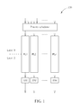
- Fig. 1 is a diagram illustrating a network device 100 according to a first embodiment of the present invention.
- the network device 100 may be a receiving device or a transmitting device in a network environment based on OSI model.
- the intercommunication between layer 2 and layer 3 is used for illustrating the first embodiment of the present invention.
- the communication protocol between layer 2 and layer 3 includes AS (access stratum) and NAS (access stratum).
- AS protocol responsible for signal handling, parameter setup or resource allocation of wireless access, includes MAC (media access control), RLC (radio link control), PDCP (packet data convergence protocol), BMC (broadcast/multicast control) and RRC (radio resource control).
- the network device 100 may be applied to a WCDMA (wide band code division multiple access) network capable of providing AS protocols having varying transmission rates (represented by AS1-ASn) for data transmission using OVSF (orthogonal variable spreading factor) encoding.
- WCDMA wide band code division multiple access
- AS1-ASn wide band code division multiple access
- OVSF orthogonal variable spreading factor
- a pipeline structure having pipelines PL1-PLn are used for parallel data transmission between layer 2 and layer 3 in the network device 100.
- the speed relationship of the AS protocols and pipelines are as follows: AS1>AS2>...>ASn and PL1>PL2>...>PLn.
- a priority scheduler is used in the network device 100 according to the first embodiment of the present invention for determining data type.
- the data is distributed to corresponding AS1-ASn via respective pipelines PL1-PLn according to data priority. For instance, a high priority control signal may be distributed to the fastest AS1 via the fastest pipeline PL1, while a low priority data signal may be distributed to the slowest ASn via the slowest pipeline PLn.
- the present invention may relocate more resources for handling high priority data, thereby enhancing the overall system efficiency.
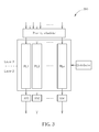
- Fig. 2 is a diagram illustrating a network device 200 according to a second embodiment of the present invention.
- the network device 200 may be a receiving device or a transmitting device in a network environment based on OSI model.
- the intercommunication between layer 2 and layer 3 is also used for illustrating the second embodiment of the present invention.
- a pipeline structure having pipelines PL1-PLn are used for parallel data transmission between layer 2 and layer 3 in the network device 200.
- the speed relationship of the pipelines is as follows PL1>PL2>...>PLn.
- a priority scheduler is used in the network device 200 so that the data may be distributed via respective pipelines PL1-PLn according to data priority.
- layer 2 only supports single rate AS protocol. Therefore, a merger is required for combining each piece of data transmitted via the pipelines PL1-PLn.
- Fig. 3 is a diagram illustrating a network device 300 according to a third embodiment of the present invention
- Fig. 4 is a diagram illustrating a network device 400 according to a fourth embodiment of the present invention.
- the network device 300 having similar structure as the network device 100, further includes a distributor.
- the network device 400 having similar structure as the network device 200, further includes a distributor.
- the distributor is configured to dynamically adjust the size of each pipeline according to the transmission status of the pipelines PL1-PLn.
- the distributor may be configured to detect pipeline parameters, such as network quality (QoS), channel quality indicator (CQI), data stall or data transfer reliability of each pipeline.
- QoS network quality
- CQI channel quality indicator
- Figs. 5-7 are diagrams illustrating the operation of the distributor according to the present invention.
- the distributor is configured to relocate resources according to the transmission rate of the pipelines PL1-PLn so that a faster pipeline may have a larger bandwidth, as depicted in Fig. 5 .
- the distributor is configured to relocate more resources to the pipeline PL2 which is the fastest pipeline still able to provide normal transmission, as depicted in Fig. 6 .
- the distributor is configured to relocate more resources to the pipeline PLn, as depicted in Fig. 7 .
- the third and fourth embodiments of the present invention may improve data throughput when facing poor pipeline transmission, thereby enhancing the overall system efficiency.
- the present invention may also be used for intercommunication between other OSI layers, or be applied to other network structures.
- data type is first determined in the present invention so as to handle high priority data using faster pipelines and handling low priority data using slower pipelines. Meanwhile, the size of each pipeline may be dynamically adjusted according to the quality of pipeline transmission, thereby enhancing the overall system efficiency.
Landscapes
- Engineering & Computer Science (AREA)
- Computer Networks & Wireless Communication (AREA)
- Signal Processing (AREA)
- Data Exchanges In Wide-Area Networks (AREA)
- Communication Control (AREA)
- Small-Scale Networks (AREA)
Abstract
Description
- The present invention is related to data transmission in a network device having a multi-layer structure according to the pre-characterizing clause of claims 1 and 9.
- With rapid development in technology, a user may easily connect to a network using desktop computers, notebook computers, personal digital assistants (PDAs) or smart phones. In order for electronic equipment having varying specifications to be able to communicate with the same network, a network model OSI (Open Systems Interconnection) has been provided by ISO (International Organization for Standardization) for managing the network intercommunication between two systems.
- The OSI model defines 7 layers for network transmission, sequentially including physical layer (layer 1), data link layer (layer 2), network layer (layer 3), transport layer(layer 4), session layer (layer5), presentation layer (layer 6), and application layer (layer 7). The 1st physical layer is defined as the bottom layer closest to hardware devices, while the 7th application layer is defined as the top layer closest to software programs. Each layer has distinct function and separate program codes. The functions and applications of the OSI model are well-known to those skilled in the art and will not be described in detail in the present invention.
- For data transmission from a transmitting network device to a receiving network device, data is transmitted from the top layer 7 sequentially to the bottom layer 1 as corresponding data packages using application programs in the transmitting network device. After receiving data packages from the bottom layer 7 of the transmitting network device, the receiving network device sequentially unpacks each data package, which is then distributed to a corresponding layer of the receiving network device. Assigned for different tasks, each layer may have varying transmission parameters and buffer sizes. Data stall may happen when transmitting data from a faster top layer to a slower bottom layer. Also, a faster bottom layer may not be able to improve data throughput if a top layer encounters insufficient data buffer or transmission blockages.
- This in mind, the present invention aims at providing data transmission in a network device having a multi-layer structure that improves overall data transmission efficiency.
- This is achieved by data transmission in a network device having a multi-layer structure according to claims 1 and 9. The dependent claims pertain to corresponding further developments and improvements.
- As will be seen more clearly from the detailed description following below, the claimed data transmission in a network device having a multi-layer structure includes pipelines with varying data rates that may be dynamically adjusted according the transmission status of each pipeline.
- The present invention provides a method for data transmission in a network device having a multi-layer structure. The method includes providing a plurality of pipelines with varying data rates for transmitting a plurality of data between a first layer and a second layer of the multi-layer structure; and transmitting each data using a corresponding pipeline among the plurality of pipelines according to a data type of each data.
- The present invention also provides a pipeline network device including a first layer circuit; a second layer circuit; a plurality of pipelines with varying data rates for transmitting a plurality of data between the first layer circuit and the second layer circuit; and a priority scheduler for distributing each data to a corresponding pipeline among the plurality of pipelines according to a data type of each data.
- In the following, the invention is further illustrated by way of example, taking reference to the accompanying drawings. Thereof
-
Figs. 1-4 are diagrams illustrating a network device according to embodiments of the present invention, and -
Figs. 5-7 are diagrams illustrating the operation of a distributor according to the present invention. -
Fig. 1 is a diagram illustrating anetwork device 100 according to a first embodiment of the present invention. Thenetwork device 100 may be a receiving device or a transmitting device in a network environment based on OSI model. The intercommunication betweenlayer 2 andlayer 3 is used for illustrating the first embodiment of the present invention. In the OSI model, the communication protocol betweenlayer 2 andlayer 3 includes AS (access stratum) and NAS (access stratum). AS protocol, responsible for signal handling, parameter setup or resource allocation of wireless access, includes MAC (media access control), RLC (radio link control), PDCP (packet data convergence protocol), BMC (broadcast/multicast control) and RRC (radio resource control). Thenetwork device 100 according to the first embodiment of the present invention may be applied to a WCDMA (wide band code division multiple access) network capable of providing AS protocols having varying transmission rates (represented by AS1-ASn) for data transmission using OVSF (orthogonal variable spreading factor) encoding. Meanwhile, a pipeline structure having pipelines PL1-PLn are used for parallel data transmission betweenlayer 2 andlayer 3 in thenetwork device 100. Under normal circumstance, the speed relationship of the AS protocols and pipelines are as follows: AS1>AS2>...>ASn and PL1>PL2>...>PLn. - For data transfer from
layer 3 tolayer 2, a priority scheduler is used in thenetwork device 100 according to the first embodiment of the present invention for determining data type. The data is distributed to corresponding AS1-ASn via respective pipelines PL1-PLn according to data priority. For instance, a high priority control signal may be distributed to the fastest AS1 via the fastest pipeline PL1, while a low priority data signal may be distributed to the slowest ASn via the slowest pipeline PLn. In other words, the present invention may relocate more resources for handling high priority data, thereby enhancing the overall system efficiency. -
Fig. 2 is a diagram illustrating anetwork device 200 according to a second embodiment of the present invention. Thenetwork device 200 may be a receiving device or a transmitting device in a network environment based on OSI model. The intercommunication betweenlayer 2 andlayer 3 is also used for illustrating the second embodiment of the present invention. Meanwhile, a pipeline structure having pipelines PL1-PLn are used for parallel data transmission betweenlayer 2 andlayer 3 in thenetwork device 200. Under normal circumstance, the speed relationship of the pipelines is as follows PL1>PL2>...>PLn. A priority scheduler is used in thenetwork device 200 so that the data may be distributed via respective pipelines PL1-PLn according to data priority. In thenetwork device 200 according to the second embodiment of the present invention,layer 2 only supports single rate AS protocol. Therefore, a merger is required for combining each piece of data transmitted via the pipelines PL1-PLn. -
Fig. 3 is a diagram illustrating anetwork device 300 according to a third embodiment of the present invention, andFig. 4 is a diagram illustrating anetwork device 400 according to a fourth embodiment of the present invention. Thenetwork device 300, having similar structure as thenetwork device 100, further includes a distributor. Thenetwork device 400, having similar structure as thenetwork device 200, further includes a distributor. The distributor is configured to dynamically adjust the size of each pipeline according to the transmission status of the pipelines PL1-PLn. For example, the distributor may be configured to detect pipeline parameters, such as network quality (QoS), channel quality indicator (CQI), data stall or data transfer reliability of each pipeline. -
Figs. 5-7 are diagrams illustrating the operation of the distributor according to the present invention. Under the circumstance when all pipelines provide normal transmission, the distributor is configured to relocate resources according to the transmission rate of the pipelines PL1-PLn so that a faster pipeline may have a larger bandwidth, as depicted inFig. 5 . If the transmission of the fastest pipeline PL1 is downgraded due to interference, the distributor is configured to relocate more resources to the pipeline PL2 which is the fastest pipeline still able to provide normal transmission, as depicted inFig. 6 . If the slowest pipeline PLn is the only one able to provide normal transmission, the distributor is configured to relocate more resources to the pipeline PLn, as depicted inFig. 7 . In other words, the third and fourth embodiments of the present invention may improve data throughput when facing poor pipeline transmission, thereby enhancing the overall system efficiency. - Although the intercommunication between
layer 2 andlayer 3 is used for illustrating the embodiments of the present invention, the present invention may also be used for intercommunication between other OSI layers, or be applied to other network structures. - For data transmission between different layers in a network device, data type is first determined in the present invention so as to handle high priority data using faster pipelines and handling low priority data using slower pipelines. Meanwhile, the size of each pipeline may be dynamically adjusted according to the quality of pipeline transmission, thereby enhancing the overall system efficiency.
Claims (12)
- A method for data transmission in a network device having a multi-layer structure, characterized byproviding a plurality of pipelines with varying data rates for transmitting a plurality of data between a first layer and a second layer of the multi-layer structure; andtransmitting each data using a corresponding pipeline among the plurality of pipelines according to a data type of each data.
- The method of claim 1, further characterized by:determining a priority of each data according to the data type of each data; andtransmitting a first data among the plurality of data using a first pipeline among the plurality of pipelines and transmitting a second data among the plurality of data using a second pipeline among the plurality of pipelines, wherein the first pipeline is faster than the second pipeline when it is determined that a priority of the first data is higher than a priority of the second data.
- The method of claim 1, further characterized by merging the plurality of data respectively transmitted via the plurality of pipelines into a single piece of data.
- The method of claim 1, further characterized by processing the plurality of data respectively transmitted via the plurality of pipelines according to a plurality of access stratum protocols having varying transmission rates.
- The method of claim 4, further characterized by:determining a priority of each data according to the data type of each data; andprocessing a first data among the plurality of data according to a first access stratum protocol among the plurality of access stratum protocols and processing a second data among the plurality of data according to a second access stratum protocol among the plurality of access stratum protocols, wherein the first access stratum protocol is faster than the second access stratum protocol when it is determined that a priority of the first data is higher than a priority of the second data.
- The method of claim 4, further characterized by:determining a priority of each data according to the data type of each data; andtransmitting a first data among the plurality of data using a first pipeline among the plurality of pipelines and transmitting a second data among the plurality of data using a second pipeline among the plurality of pipelines; andprocessing a first data among the plurality of data according to a first access stratum protocol among the plurality of access stratum protocols and processing a second data among the plurality of data according to a second access stratum protocol among the plurality of access stratum protocols, wherein the first pipeline is faster than the second pipeline and the first access stratum protocol is faster than the second access stratum protocol when it is determined that a priority of the first data is higher than a priority of the second data.
- The method of claim 1, further characterized by dynamically adjusting a size of each pipeline according to a transmission status of the plurality of pipelines.
- The method of claim 7, further characterized by detecting a network quality of service, a channel quality indicator, and a data stall or a data transfer reliability of each pipeline for dynamically adjusting the size of each pipeline among the plurality of pipelines.
- A pipeline network device (100, 200, 300, 400), comprising:a first layer circuit;a second layer circuit;characterized bya plurality of pipelines with varying data rates for transmitting a plurality of data between the first layer circuit and the second layer circuit; anda priority scheduler for distributing each data to a corresponding pipeline among the plurality of pipelines according to a data type of each data.
- The device (200, 400) of claim 9, further characterized by a merger for merging the plurality of data respectively transmitted via the plurality of pipelines into a single piece of data.
- The device (300, 400) of claim 9, further characterized by a distributor for dynamically adjusting a size of each pipeline according to a transmission status of the plurality of pipelines.
- The device (300, 400) of claim 11, further characterized in that the distributor is configured to dynamically adjust the size of each pipeline according to a network quality, a channel quality indicator, a data stall or a data transfer reliability of each pipeline.
Applications Claiming Priority (1)
| Application Number | Priority Date | Filing Date | Title |
|---|---|---|---|
| TW100103628A TWI423129B (en) | 2011-01-31 | 2011-01-31 | Pipeline network device and related data transmission method |
Publications (2)
| Publication Number | Publication Date |
|---|---|
| EP2482501A1 true EP2482501A1 (en) | 2012-08-01 |
| EP2482501B1 EP2482501B1 (en) | 2013-10-16 |
Family
ID=44759393
Family Applications (1)
| Application Number | Title | Priority Date | Filing Date |
|---|---|---|---|
| EP11166503.0A Active EP2482501B1 (en) | 2011-01-31 | 2011-05-18 | Pipeline network device and related data transmission method |
Country Status (4)
| Country | Link |
|---|---|
| US (1) | US8774193B2 (en) |
| EP (1) | EP2482501B1 (en) |
| CN (1) | CN102624769B (en) |
| TW (1) | TWI423129B (en) |
Cited By (1)
| Publication number | Priority date | Publication date | Assignee | Title |
|---|---|---|---|---|
| CN106303657A (en) * | 2016-08-18 | 2017-01-04 | 北京奇虎科技有限公司 | A kind of even method that wheat is live and main broadcaster's end equipment |
Families Citing this family (4)
| Publication number | Priority date | Publication date | Assignee | Title |
|---|---|---|---|---|
| WO2011014118A1 (en) * | 2009-07-28 | 2011-02-03 | Oricane Ab | Method for managing multi-layered data structures in a pipelined memory architecture |
| US11755926B2 (en) * | 2019-02-28 | 2023-09-12 | International Business Machines Corporation | Prioritization and prediction of jobs using cognitive rules engine |
| US11245600B2 (en) * | 2019-07-18 | 2022-02-08 | Citrix Systems, Inc. | System and method for processing network data |
| CN112183668B (en) * | 2020-11-03 | 2022-07-22 | 支付宝(杭州)信息技术有限公司 | Method and device for training service models in parallel |
Citations (3)
| Publication number | Priority date | Publication date | Assignee | Title |
|---|---|---|---|---|
| WO2002019619A2 (en) * | 2000-08-28 | 2002-03-07 | Nokia Corporation | Basic quality of service (qos) mechanisms for wireless transmission of ip traffic |
| EP1643690A1 (en) * | 2004-10-01 | 2006-04-05 | Matsushita Electric Industrial Co., Ltd. | Quality-of-Service (QoS)-aware scheduling for uplink transmissions on dedicated channels |
| WO2009145354A1 (en) * | 2008-05-30 | 2009-12-03 | Sharp Kabushiki Kaisha | Systems and methods for reducing feedback overhead in wireless networks using channel characteristics |
Family Cites Families (12)
| Publication number | Priority date | Publication date | Assignee | Title |
|---|---|---|---|---|
| US7016363B1 (en) * | 2000-10-19 | 2006-03-21 | Interactic Holdings, Llc | Scaleable interconnect structure utilizing quality-of-service handling |
| CN100401731C (en) * | 2002-06-15 | 2008-07-09 | 华为技术有限公司 | High-speed data link control protocol receiving processing module and data processing method thereof |
| DE60319975T2 (en) * | 2003-07-31 | 2009-05-07 | Nokia Siemens Networks Gmbh & Co.Kg | A method of managing common radio resources in a cellular telephone network |
| CN100399770C (en) * | 2004-08-18 | 2008-07-02 | 华为技术有限公司 | Uploading controller channel current limiting method |
| TWI257790B (en) * | 2004-10-29 | 2006-07-01 | Ind Tech Res Inst | System for protocol processing engine |
| WO2007117218A1 (en) * | 2006-04-12 | 2007-10-18 | Panasonic Corporation | Transmission of multicast/broadcast services in a wireless communication network |
| CN101325578A (en) * | 2007-06-15 | 2008-12-17 | 中兴通讯股份有限公司 | A method and system for realizing different rate line bonding |
| US8280377B2 (en) * | 2007-10-05 | 2012-10-02 | Lg Electronics Inc. | Method of performing cell reselection in wireless communication system |
| EP2077690B1 (en) * | 2008-01-07 | 2015-03-18 | LG Electronics Inc. | Method of reselecting a cell based on priorities |
| CN101552726B (en) * | 2009-05-14 | 2012-01-11 | 北京交通大学 | A Hierarchical Service Edge Router |
| CN101895514A (en) * | 2009-05-20 | 2010-11-24 | 灰熊(北京)科技有限公司 | Client data information loading method capable of distributing server stress |
| CN101668005B (en) * | 2009-09-25 | 2012-04-25 | 东南大学 | Data transmission accelerating engine method based on multiple access passages of transmitting end |
-
2011
- 2011-01-31 TW TW100103628A patent/TWI423129B/en not_active IP Right Cessation
- 2011-03-09 CN CN201110056290.8A patent/CN102624769B/en active Active
- 2011-04-28 US US13/095,880 patent/US8774193B2/en active Active
- 2011-05-18 EP EP11166503.0A patent/EP2482501B1/en active Active
Patent Citations (3)
| Publication number | Priority date | Publication date | Assignee | Title |
|---|---|---|---|---|
| WO2002019619A2 (en) * | 2000-08-28 | 2002-03-07 | Nokia Corporation | Basic quality of service (qos) mechanisms for wireless transmission of ip traffic |
| EP1643690A1 (en) * | 2004-10-01 | 2006-04-05 | Matsushita Electric Industrial Co., Ltd. | Quality-of-Service (QoS)-aware scheduling for uplink transmissions on dedicated channels |
| WO2009145354A1 (en) * | 2008-05-30 | 2009-12-03 | Sharp Kabushiki Kaisha | Systems and methods for reducing feedback overhead in wireless networks using channel characteristics |
Cited By (1)
| Publication number | Priority date | Publication date | Assignee | Title |
|---|---|---|---|---|
| CN106303657A (en) * | 2016-08-18 | 2017-01-04 | 北京奇虎科技有限公司 | A kind of even method that wheat is live and main broadcaster's end equipment |
Also Published As
| Publication number | Publication date |
|---|---|
| TWI423129B (en) | 2014-01-11 |
| CN102624769B (en) | 2015-10-21 |
| US20120198463A1 (en) | 2012-08-02 |
| CN102624769A (en) | 2012-08-01 |
| TW201232395A (en) | 2012-08-01 |
| EP2482501B1 (en) | 2013-10-16 |
| US8774193B2 (en) | 2014-07-08 |
Similar Documents
| Publication | Publication Date | Title |
|---|---|---|
| CN111937364B (en) | Method and system for processing data path creation in wireless network system | |
| US20080049617A1 (en) | System for fine grained flow-control concurrency to prevent excessive packet loss | |
| KR101560613B1 (en) | Hybrid networking path selection and load balancing | |
| CN103503553B (en) | Communication method for terminal and access point for uplink MU-MIMO channel access | |
| US20140219112A1 (en) | Selective prioritization of data packets to improve data traffic | |
| JP7769501B2 (en) | Method and apparatus for facilitating data transmission | |
| WO2016187813A1 (en) | Data transmission method and device for photoelectric hybrid network | |
| US11252608B2 (en) | Method and apparatus for transmitting data in wireless communication system | |
| US9813530B2 (en) | Apparatus, system and method of controlling data flow over a communication network | |
| US8774193B2 (en) | Pipeline network device and related data transmission method | |
| CN102185771A (en) | Dispatching method and system for data packet of sender in MPTCP (Multipath TCP (Transmission Control Protocol)) | |
| CN112039639A (en) | Feedback indication method and communication device | |
| CN103401778B (en) | Based on the multi-path transmission grouping scheduling method that receiving terminal cache overflow probability is ensured | |
| CN112261723B (en) | Uplink control information transmission method and device | |
| US10582410B2 (en) | Predicting downlink throughput | |
| WO2023217009A1 (en) | Data transmission method and apparatus and communication device | |
| CN105897767A (en) | Scheduling method, equipment and system and scheduling response method and equipment | |
| CN105453681A (en) | A data scheduling method and apparatus | |
| CN103718488B (en) | For the expansible information package of information transmission and the method and system of polymerization in communication network | |
| WO2017040948A1 (en) | Enabling time flexibility for block transfer in coap protocol | |
| US20250386275A1 (en) | Low latency processing for wifi or wireless networks and routers | |
| US20250227072A1 (en) | Host-controller interface (hci) communication | |
| CN118054889A (en) | Retransmission window determining method, retransmission window determining device and storage medium | |
| Elahi et al. | A distributed SCTP scheme for bandwidth aggregation | |
| CN106506434A (en) | Service data transmission method and device |
Legal Events
| Date | Code | Title | Description |
|---|---|---|---|
| PUAI | Public reference made under article 153(3) epc to a published international application that has entered the european phase |
Free format text: ORIGINAL CODE: 0009012 |
|
| AK | Designated contracting states |
Kind code of ref document: A1 Designated state(s): AL AT BE BG CH CY CZ DE DK EE ES FI FR GB GR HR HU IE IS IT LI LT LU LV MC MK MT NL NO PL PT RO RS SE SI SK SM TR |
|
| AX | Request for extension of the european patent |
Extension state: BA ME |
|
| 17P | Request for examination filed |
Effective date: 20121010 |
|
| REG | Reference to a national code |
Ref country code: DE Ref legal event code: R079 Ref document number: 602011003369 Country of ref document: DE Free format text: PREVIOUS MAIN CLASS: H04L0012560000 Ipc: H04W0072120000 |
|
| RIC1 | Information provided on ipc code assigned before grant |
Ipc: H04W 72/12 20090101AFI20130115BHEP |
|
| GRAP | Despatch of communication of intention to grant a patent |
Free format text: ORIGINAL CODE: EPIDOSNIGR1 |
|
| INTG | Intention to grant announced |
Effective date: 20130429 |
|
| RIN1 | Information on inventor provided before grant (corrected) |
Inventor name: CHENG, TSUNG-YO |
|
| GRAS | Grant fee paid |
Free format text: ORIGINAL CODE: EPIDOSNIGR3 |
|
| GRAA | (expected) grant |
Free format text: ORIGINAL CODE: 0009210 |
|
| AK | Designated contracting states |
Kind code of ref document: B1 Designated state(s): AL AT BE BG CH CY CZ DE DK EE ES FI FR GB GR HR HU IE IS IT LI LT LU LV MC MK MT NL NO PL PT RO RS SE SI SK SM TR |
|
| REG | Reference to a national code |
Ref country code: GB Ref legal event code: FG4D |
|
| REG | Reference to a national code |
Ref country code: CH Ref legal event code: EP |
|
| REG | Reference to a national code |
Ref country code: IE Ref legal event code: FG4D |
|
| REG | Reference to a national code |
Ref country code: AT Ref legal event code: REF Ref document number: 637008 Country of ref document: AT Kind code of ref document: T Effective date: 20131115 |
|
| REG | Reference to a national code |
Ref country code: DE Ref legal event code: R096 Ref document number: 602011003369 Country of ref document: DE Effective date: 20131212 |
|
| REG | Reference to a national code |
Ref country code: NL Ref legal event code: VDEP Effective date: 20131016 |
|
| REG | Reference to a national code |
Ref country code: AT Ref legal event code: MK05 Ref document number: 637008 Country of ref document: AT Kind code of ref document: T Effective date: 20131016 |
|
| REG | Reference to a national code |
Ref country code: LT Ref legal event code: MG4D |
|
| PG25 | Lapsed in a contracting state [announced via postgrant information from national office to epo] |
Ref country code: NO Free format text: LAPSE BECAUSE OF FAILURE TO SUBMIT A TRANSLATION OF THE DESCRIPTION OR TO PAY THE FEE WITHIN THE PRESCRIBED TIME-LIMIT Effective date: 20140116 Ref country code: BE Free format text: LAPSE BECAUSE OF FAILURE TO SUBMIT A TRANSLATION OF THE DESCRIPTION OR TO PAY THE FEE WITHIN THE PRESCRIBED TIME-LIMIT Effective date: 20131016 Ref country code: SE Free format text: LAPSE BECAUSE OF FAILURE TO SUBMIT A TRANSLATION OF THE DESCRIPTION OR TO PAY THE FEE WITHIN THE PRESCRIBED TIME-LIMIT Effective date: 20131016 Ref country code: HR Free format text: LAPSE BECAUSE OF FAILURE TO SUBMIT A TRANSLATION OF THE DESCRIPTION OR TO PAY THE FEE WITHIN THE PRESCRIBED TIME-LIMIT Effective date: 20131016 Ref country code: FI Free format text: LAPSE BECAUSE OF FAILURE TO SUBMIT A TRANSLATION OF THE DESCRIPTION OR TO PAY THE FEE WITHIN THE PRESCRIBED TIME-LIMIT Effective date: 20131016 Ref country code: NL Free format text: LAPSE BECAUSE OF FAILURE TO SUBMIT A TRANSLATION OF THE DESCRIPTION OR TO PAY THE FEE WITHIN THE PRESCRIBED TIME-LIMIT Effective date: 20131016 Ref country code: IS Free format text: LAPSE BECAUSE OF FAILURE TO SUBMIT A TRANSLATION OF THE DESCRIPTION OR TO PAY THE FEE WITHIN THE PRESCRIBED TIME-LIMIT Effective date: 20140216 Ref country code: LT Free format text: LAPSE BECAUSE OF FAILURE TO SUBMIT A TRANSLATION OF THE DESCRIPTION OR TO PAY THE FEE WITHIN THE PRESCRIBED TIME-LIMIT Effective date: 20131016 |
|
| PG25 | Lapsed in a contracting state [announced via postgrant information from national office to epo] |
Ref country code: AT Free format text: LAPSE BECAUSE OF FAILURE TO SUBMIT A TRANSLATION OF THE DESCRIPTION OR TO PAY THE FEE WITHIN THE PRESCRIBED TIME-LIMIT Effective date: 20131016 Ref country code: LV Free format text: LAPSE BECAUSE OF FAILURE TO SUBMIT A TRANSLATION OF THE DESCRIPTION OR TO PAY THE FEE WITHIN THE PRESCRIBED TIME-LIMIT Effective date: 20131016 Ref country code: CY Free format text: LAPSE BECAUSE OF FAILURE TO SUBMIT A TRANSLATION OF THE DESCRIPTION OR TO PAY THE FEE WITHIN THE PRESCRIBED TIME-LIMIT Effective date: 20131016 Ref country code: RS Free format text: LAPSE BECAUSE OF FAILURE TO SUBMIT A TRANSLATION OF THE DESCRIPTION OR TO PAY THE FEE WITHIN THE PRESCRIBED TIME-LIMIT Effective date: 20131016 Ref country code: ES Free format text: LAPSE BECAUSE OF FAILURE TO SUBMIT A TRANSLATION OF THE DESCRIPTION OR TO PAY THE FEE WITHIN THE PRESCRIBED TIME-LIMIT Effective date: 20131016 |
|
| PG25 | Lapsed in a contracting state [announced via postgrant information from national office to epo] |
Ref country code: PT Free format text: LAPSE BECAUSE OF FAILURE TO SUBMIT A TRANSLATION OF THE DESCRIPTION OR TO PAY THE FEE WITHIN THE PRESCRIBED TIME-LIMIT Effective date: 20140217 |
|
| REG | Reference to a national code |
Ref country code: DE Ref legal event code: R097 Ref document number: 602011003369 Country of ref document: DE |
|
| PG25 | Lapsed in a contracting state [announced via postgrant information from national office to epo] |
Ref country code: EE Free format text: LAPSE BECAUSE OF FAILURE TO SUBMIT A TRANSLATION OF THE DESCRIPTION OR TO PAY THE FEE WITHIN THE PRESCRIBED TIME-LIMIT Effective date: 20131016 |
|
| PLBE | No opposition filed within time limit |
Free format text: ORIGINAL CODE: 0009261 |
|
| STAA | Information on the status of an ep patent application or granted ep patent |
Free format text: STATUS: NO OPPOSITION FILED WITHIN TIME LIMIT |
|
| PG25 | Lapsed in a contracting state [announced via postgrant information from national office to epo] |
Ref country code: RO Free format text: LAPSE BECAUSE OF FAILURE TO SUBMIT A TRANSLATION OF THE DESCRIPTION OR TO PAY THE FEE WITHIN THE PRESCRIBED TIME-LIMIT Effective date: 20131016 Ref country code: PL Free format text: LAPSE BECAUSE OF FAILURE TO SUBMIT A TRANSLATION OF THE DESCRIPTION OR TO PAY THE FEE WITHIN THE PRESCRIBED TIME-LIMIT Effective date: 20131016 Ref country code: IT Free format text: LAPSE BECAUSE OF FAILURE TO SUBMIT A TRANSLATION OF THE DESCRIPTION OR TO PAY THE FEE WITHIN THE PRESCRIBED TIME-LIMIT Effective date: 20131016 Ref country code: SK Free format text: LAPSE BECAUSE OF FAILURE TO SUBMIT A TRANSLATION OF THE DESCRIPTION OR TO PAY THE FEE WITHIN THE PRESCRIBED TIME-LIMIT Effective date: 20131016 Ref country code: CZ Free format text: LAPSE BECAUSE OF FAILURE TO SUBMIT A TRANSLATION OF THE DESCRIPTION OR TO PAY THE FEE WITHIN THE PRESCRIBED TIME-LIMIT Effective date: 20131016 |
|
| 26N | No opposition filed |
Effective date: 20140717 |
|
| PG25 | Lapsed in a contracting state [announced via postgrant information from national office to epo] |
Ref country code: DK Free format text: LAPSE BECAUSE OF FAILURE TO SUBMIT A TRANSLATION OF THE DESCRIPTION OR TO PAY THE FEE WITHIN THE PRESCRIBED TIME-LIMIT Effective date: 20131016 |
|
| REG | Reference to a national code |
Ref country code: DE Ref legal event code: R097 Ref document number: 602011003369 Country of ref document: DE Effective date: 20140717 |
|
| PG25 | Lapsed in a contracting state [announced via postgrant information from national office to epo] |
Ref country code: LU Free format text: LAPSE BECAUSE OF FAILURE TO SUBMIT A TRANSLATION OF THE DESCRIPTION OR TO PAY THE FEE WITHIN THE PRESCRIBED TIME-LIMIT Effective date: 20140518 |
|
| REG | Reference to a national code |
Ref country code: CH Ref legal event code: PL |
|
| PG25 | Lapsed in a contracting state [announced via postgrant information from national office to epo] |
Ref country code: MC Free format text: LAPSE BECAUSE OF FAILURE TO SUBMIT A TRANSLATION OF THE DESCRIPTION OR TO PAY THE FEE WITHIN THE PRESCRIBED TIME-LIMIT Effective date: 20131016 Ref country code: LI Free format text: LAPSE BECAUSE OF NON-PAYMENT OF DUE FEES Effective date: 20140531 Ref country code: CH Free format text: LAPSE BECAUSE OF NON-PAYMENT OF DUE FEES Effective date: 20140531 |
|
| REG | Reference to a national code |
Ref country code: IE Ref legal event code: MM4A |
|
| PG25 | Lapsed in a contracting state [announced via postgrant information from national office to epo] |
Ref country code: SI Free format text: LAPSE BECAUSE OF FAILURE TO SUBMIT A TRANSLATION OF THE DESCRIPTION OR TO PAY THE FEE WITHIN THE PRESCRIBED TIME-LIMIT Effective date: 20131016 |
|
| PG25 | Lapsed in a contracting state [announced via postgrant information from national office to epo] |
Ref country code: IE Free format text: LAPSE BECAUSE OF NON-PAYMENT OF DUE FEES Effective date: 20140518 |
|
| PG25 | Lapsed in a contracting state [announced via postgrant information from national office to epo] |
Ref country code: MT Free format text: LAPSE BECAUSE OF FAILURE TO SUBMIT A TRANSLATION OF THE DESCRIPTION OR TO PAY THE FEE WITHIN THE PRESCRIBED TIME-LIMIT Effective date: 20131016 |
|
| REG | Reference to a national code |
Ref country code: FR Ref legal event code: PLFP Year of fee payment: 6 |
|
| PG25 | Lapsed in a contracting state [announced via postgrant information from national office to epo] |
Ref country code: SM Free format text: LAPSE BECAUSE OF FAILURE TO SUBMIT A TRANSLATION OF THE DESCRIPTION OR TO PAY THE FEE WITHIN THE PRESCRIBED TIME-LIMIT Effective date: 20131016 |
|
| PG25 | Lapsed in a contracting state [announced via postgrant information from national office to epo] |
Ref country code: BG Free format text: LAPSE BECAUSE OF FAILURE TO SUBMIT A TRANSLATION OF THE DESCRIPTION OR TO PAY THE FEE WITHIN THE PRESCRIBED TIME-LIMIT Effective date: 20131016 Ref country code: GR Free format text: LAPSE BECAUSE OF FAILURE TO SUBMIT A TRANSLATION OF THE DESCRIPTION OR TO PAY THE FEE WITHIN THE PRESCRIBED TIME-LIMIT Effective date: 20140117 |
|
| PG25 | Lapsed in a contracting state [announced via postgrant information from national office to epo] |
Ref country code: TR Free format text: LAPSE BECAUSE OF FAILURE TO SUBMIT A TRANSLATION OF THE DESCRIPTION OR TO PAY THE FEE WITHIN THE PRESCRIBED TIME-LIMIT Effective date: 20131016 Ref country code: HU Free format text: LAPSE BECAUSE OF FAILURE TO SUBMIT A TRANSLATION OF THE DESCRIPTION OR TO PAY THE FEE WITHIN THE PRESCRIBED TIME-LIMIT; INVALID AB INITIO Effective date: 20110518 |
|
| REG | Reference to a national code |
Ref country code: FR Ref legal event code: PLFP Year of fee payment: 7 |
|
| REG | Reference to a national code |
Ref country code: FR Ref legal event code: PLFP Year of fee payment: 8 |
|
| PG25 | Lapsed in a contracting state [announced via postgrant information from national office to epo] |
Ref country code: MK Free format text: LAPSE BECAUSE OF FAILURE TO SUBMIT A TRANSLATION OF THE DESCRIPTION OR TO PAY THE FEE WITHIN THE PRESCRIBED TIME-LIMIT Effective date: 20131016 |
|
| PG25 | Lapsed in a contracting state [announced via postgrant information from national office to epo] |
Ref country code: AL Free format text: LAPSE BECAUSE OF FAILURE TO SUBMIT A TRANSLATION OF THE DESCRIPTION OR TO PAY THE FEE WITHIN THE PRESCRIBED TIME-LIMIT Effective date: 20131016 |
|
| REG | Reference to a national code |
Ref country code: DE Ref legal event code: R082 Ref document number: 602011003369 Country of ref document: DE Representative=s name: STRAUS, ALEXANDER, DIPL.-CHEM.UNIV. DR.PHIL., DE Ref country code: DE Ref legal event code: R082 Ref document number: 602011003369 Country of ref document: DE Representative=s name: 2K PATENT- UND RECHTSANWAELTE PARTNERSCHAFT MB, DE |
|
| REG | Reference to a national code |
Ref country code: FR Ref legal event code: PLFP Year of fee payment: 13 |
|
| REG | Reference to a national code |
Ref country code: DE Ref legal event code: R082 Ref document number: 602011003369 Country of ref document: DE Representative=s name: STRAUS, ALEXANDER, DIPL.-CHEM.UNIV. DR.PHIL., DE |
|
| PGFP | Annual fee paid to national office [announced via postgrant information from national office to epo] |
Ref country code: FR Payment date: 20250321 Year of fee payment: 15 |
|
| PGFP | Annual fee paid to national office [announced via postgrant information from national office to epo] |
Ref country code: GB Payment date: 20250327 Year of fee payment: 15 |
|
| PGFP | Annual fee paid to national office [announced via postgrant information from national office to epo] |
Ref country code: DE Payment date: 20250325 Year of fee payment: 15 |